Pavement design for specialist surfacings January 2014
|
|
|
- Cameron Hardy
- 5 years ago
- Views:
Transcription
1 Pavement design for specialist surfacings January 2014 G Arnold, A Stubbs and J Vercoe Road Science NZ Transport Agency research report 543 Contracted research organisation Road Science
2 ISBN (electronic) ISSN (electronic) NZ Transport Agency Private Bag 6995, Wellington 6141, New Zealand Telephone ; facsimile research@nzta.govt.nz Arnold, G, A Stubbs and J Vercoe (2014) Pavement design for specialist surfacings. NZ Transport Agency research report pp. Road Science was contracted by the NZ Transport Agency in 2012 to carry out this research. This publication is copyright NZ Transport Agency Material in it may be reproduced for personal or in-house use without formal permission or charge, provided suitable acknowledgement is made to this publication and the NZ Transport Agency as the source. Requests and enquiries about the reproduction of material in this publication for any other purpose should be made to the Manager National Programmes, Investment Team, NZ Transport Agency, at research@nzta.govt.nz. Keywords: calcined bauxite, coloured surfacings, epoxy resin binder, flexural beam test, high-friction surfaces, Leutner shear and bond strength tester, pavement design, polyurethane binder, skid resistance, specialist surfacings.
3 An important note for the reader The NZ Transport Agency is a Crown entity established under the Land Transport Management Act The objective of the Agency is to undertake its functions in a way that contributes to an efficient, effective and safe land transport system in the public interest. Each year, the NZ Transport Agency funds innovative and relevant research that contributes to this objective. The views expressed in research reports are the outcomes of the independent research, and should not be regarded as being the opinion or responsibility of the NZ Transport Agency. The material contained in the reports should not be construed in any way as policy adopted by the NZ Transport Agency or indeed any agency of the NZ Government. The reports may, however, be used by NZ Government agencies as a reference in the development of policy. While research reports are believed to be correct at the time of their preparation, the NZ Transport Agency and agents involved in their preparation and publication do not accept any liability for use of the research. People using the research, whether directly or indirectly, should apply and rely on their own skill and judgement. They should not rely on the contents of the research reports in isolation from other sources of advice and information. If necessary, they should seek appropriate legal or other expert advice.
4 Acknowledgements The author acknowledges the contributions by the NZ Transport Agency project manager, the Steering Group members and the two peer reviewers. NZ Transport Agency Project Manager and Steering Group Chair: Joanna Towler, NZ Transport Agency Steering Group members: David Cook, NZ Transport Agency Simon Fletcher, Fletcher Corporation Ltd Delia Moraru, Auckland Transport Peer reviewers: John Patrick, Opus Research Bruce Chappell, Beca Abbreviations and acronyms DSR FWD OGPA SAMI Transport Agency dynamic shear rheometer falling weight deflectometer open graded porous asphalt strain alleviating membrane interlayer New Zealand Transport Agency
5 Contents Executive summary... 7 Abstract Introduction Background Objectives Literature review Flexural beam test Leutner shear test Laboratory testing flexural beam test Flexural beam test Laboratory testing Leutner shear test Leutner shear test Thermal effects Simplified theoretical model Recommended developments Pavement deflection criteria Introduction Top down cracking Bending-induced surface tension Pavement curvature Shear-induced near-surface tension at the tyre edge Specification criteria Tensile strain criteria for 10mm pavement rutting Leutner shear bond strength criteria Other tests Conclusions Recommendations References
6 6
7 Executive summary There are a range of different specialist surfacings on the market, for example, the coloured surfaces used at bus stops and calcined bauxite high-friction surfacings used at intersections and off ramps. These specialist surfacings are not bitumen based but are typically polyurethane or epoxy resin based. Some of these surfacings have not met their life expectations and the New Zealand Transport Agency (Transport Agency) in their request for research proposals asked: How do we ensure the existing road and the new surfacing are compatible in terms of their respective stiffnesses to ensure the surfacing will deliver the expected life? What do we do when the stiffness is not compatible? The Transport Agency also stated in the research tender document that some surfacings such as slurry seals and calcined bauxite needed a certain minimum pavement stiffness or maximum curvature, to ensure the surfacing would adhere to the pavement for its intended life. In addressing the above questions, the researchers conducted a limited study into specialist surfacings, which focused initially on flexibility and developing limiting pavement deflection criteria. It was hypothesised that the specialist surfacing could not be used in places with high pavement deflections. However, it was found that all the specialist surfacing resins, except one, were highly flexible and should cope with very high pavement deflections. In fact, the flexibility of the resins showed they could cope with rut depths in excess of 10mm. The asphalt itself would crack before the specialist surfacing resins did. Nevertheless, one important property for the specialist binders to have is flexibility. Four of the five specialist binders showed exceptional flexibility and thus flexibility criteria could be developed to exclude the fifth product that was more brittle than the other products (although some field data is needed to give reasons why this product should be excluded through a specification change). The initial research proposal focused on flexural beam tests to measure strength and flexibility; however, the researchers in agreement with the Steering Committee and the Transport Agency extended the research scope to include the Leutner shear test for bond and asphalt strength. This is a simple and promising test. Results clearly showed that four of the five specialist surfacing resins required the asphalt surface to be water cut while one resin showed exceptional performance giving full bond strength on fresh asphalt surfaces that were not water cut. Full bond strength is achieved when the Leutner shear strength at break is equal to the asphalt shear strength indicating failure in the asphalt and not the bond. Field cores could also be tested in the Leutner shear test to determine whether or not full bond strength was obtained. Results from this study determined a Leutner shear test for bond strength could be included in a specification for specialist surfacings, with the pass criterion being when the bond strength exceeds the shear strength of the asphalt mix. However, further research is needed on a test for flexibility as the large scale flexural beam tests on the resin binder only were difficult to interpret in terms of determining a pass or fail result. Binder property tests like the dynamic shear rheometer or a direct tensile test could be more appropriate. 7
8 Pavement design for specialist surfacings Abstract Leutner shear tests to measure bond strength and flexural beam tests to measure flexibility were conducted on specialist surfacing resins used in New Zealand for coloured and high-friction surfacings. The flexural beam tests found the specialist surfacing resins, except for one, to be very flexible at 5 and 20 degree test temperatures. This flexibility showed that the specialist surfacing resins should be able to cope with high pavement deflections and rut depths up to 20mm and the underlying asphalt would crack before the specialist surfacing did. Leutner shear tests showed one out of five resins tested on fresh asphalt cores achieved full bond strength (the same as the asphalt mix shear strength) and all resins achieved the full bond strength when the asphalt surface was water cut before applying the specialist surfacing resin. 8
9 1 Introduction 1 Introduction 1.1 Background There are a range of different specialist surfacings on the market, for example coloured surfaces used at bus stops and calcined bauxite high-friction surfacings used at intersections and off ramps. These specialist surfacings are not bitumen based but are typically polyurethane or epoxy resin based. Some of these surfacings have not met their life expectations and the New Zealand Transport Agency (Transport Agency) in their request for research proposals asked: How do we ensure the existing road and the new surfacing are compatible in terms of their respective stiffnesses to ensure the surfacing will deliver the expected life? What do we do when the stiffness is not compatible? The Transport Agency also stated in the research tender document that some surfacings such as slurry seals and calcined bauxite needed a certain minimum pavement stiffness or maximum curvature to ensure the surfacing remained adhered to the pavement for its intended life. To address the above questions the research originally proposed to focus on flexural beam testing. The bending beam simulates bending of the specialist surfacing in the pavement under the wheel load. Testing would thus determine whether or not the specialist surfacing binder would have enough flexibility to cope with deflection due to the traffic loadings, or would determine the maximum pavement deflection that would not damage specialist surfacing material. However, the Steering Group meeting changed the focus of the research to include a significant amount of Leutner shear bond tests to measure the strength of the bond between the specialist surfacing and the asphalt. The Leutner test was also used to measure the shear strength of a range of different asphalt mixes as it could be the asphalt mix that failed, rather than the bond, due to the high stopping forces on the high-friction surfacing. 1.2 Objectives As a result of the Steering Group meeting, the principal objectives of the research were changed to: determine the stiffness and tensile strength of a range of specialist surfaces binders in flexural beam tests develop pavement deflection criteria from the flexural beam test results on the specialist surfacing binder develop a lab testing method that enabled pavement deflection criteria to be determined for any new specialist surfacing (ie catered for a range of different specialist surfacing mixes with different material properties) determine the maximum rut the specialist surfacing could deflect into without cracking and a methodology to estimate the rut depth of the underlying pavement develop acceptance criteria with a test method for bond strength using the Leutner shear strength test on a range of specialist surfacing mixes and asphalt types 9
10 Pavement design for specialist surfacings develop criteria for maximum difference between thermal expansion of the specialist surface and asphalt underneath to ensure the specialist surface did not fail prematurely. The Steering Group agreed to focus the research on testing epoxy and polyurethane binders used in coloured and high-friction calcined bauxite surfacings and not to cover slurries, although these could be assessed in the future using the flexural beam and Leutner shear bond tests. 10

11 2 Literature review 2 Literature review This research project used the flexural beam and Leutner shear strength bond tests to assess the specialist surfacing binders. The background and details of these tests are described in this chapter. 2.1 Flexural beam test Flexural beam testing loads support beams while recording central deflection on top of the beam (figure 2.1). Figure 2.1 Flexural beam test Source: Austroads (2008) 11
12 Pavement design for specialist surfacings Figure 2.2 Diagram of the flexural beam test (note dimensions are example only. Span can also be 300mm for 100 by 100mm beams or any width and depth) Central deflection measured here Load, P Beam- width = height = 150mm 150mm 150mm 150mm ε t : σ t L = 450mm Horizontal tensile strain and stress calculated here. Also flexural stiffness (ie stress/strain) is calculated. Prior to fatigue testing, strength tests are undertaken by applying a constant load rate P (figure 2.2) until the sample breaks or no further load can be sustained. The strength of the specimen is simply the maximum load P. Applying a repetitive load, usually for 100 cycles, allows the flexural modulus/stiffness to be calculated. The fatigue life is the number of repetitive load cycles required until the modulus is half the initial modulus. Flexural stiffness is calculated using equation 2.1: 3 23PL S max = 3 108wh δ Equation 2.1 Where: S max = flexural stiffness in Pascals P = peak force in Newtons L = beam span w = specimen width in metres h = specimen height in metres δ = peak mid-span displacement in metres. 12
 together with the pavement design software CIRCLY allow the designer to check the life of cement bound layer ( stabilised material in figure 2.3).")
13 2 Literature review The flexural beam test has recently been used for the design of stabilised pavements in New Zealand ( The Austroads pavement design guide (Austroads 2004) together with the pavement design software CIRCLY allow the designer to check the life of cement bound layer ( stabilised material in figure 2.3). To ensure the stabilised material maintains strength over the design life it is important that the stabilised material has sufficient thickness and is well supported to prevent a return to unbound behaviour. To ensure this occurs a tensile strain criterion (life N = (k/strain) 12 ) found from flexural beam tests should be used in the design. Flexural beam tests allow the designer to determine their own mix of specific design tensile strain criteria which will result in more appropriate and economic pavement designs. A range of moduli and strengths is obtained depending on the stabilised mix (figure 2.4), thus it is important to do the tests. Figure 2.3 Pavement design Stabilised Material, E CT ν CT εt_ctb Life, N = (k/ ε t_ctb ) 12 ν GR U/B Granular E GR Subgrade E SG ν SG εv_sg Figure 2.4 Flexural beam breakage tests The constant k in the fatigue equation, N = (k/strain) 12 is determined by the maximum stress and modulus from the flexural beam breakage test as found by Arnold et al (2011) to ensure the working tensile stress is below 40% of the beam tensile strength (TSmax). 13

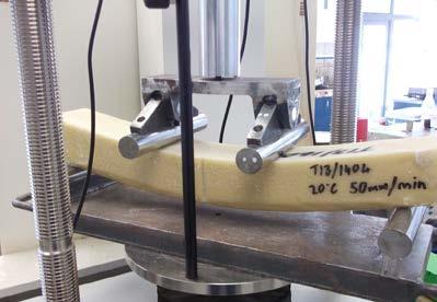
14 Pavement design for specialist surfacings TS k= max modulus Equation 2.2 The flexural beam tests will determine the maximum strain and stress at break for the specialist surfacing binders. These values can then be used to determine the maximum pavement deflection and rut depth that is possible before the specialist surfacings may break or crack. 2.2 Leutner shear test The Leutner test was developed in Germany in the late 1970s as a simple means of undertaking a direct shear test on the bond between two asphalt layers. The test applies a constant shear displacement rate across the interface under investigation and the resulting shear force is monitored. The test is normally carried out on cores comprising at least two layers and the standard loading (displacement) rate and temperature are 50 mm/minute and 20 o C, respectively. The Leutner shear test is different from the direct shear box test because normal force is not applied. Applying a normal force which would better replicate traffic loading adds unnecessary complexity and ultimately an extra expense to the test. This is because the bond strength is considered adequate when it exceeds the shear strength of the asphalt mix. Applying a normal force will increase both the bond strength and the shear strength of the asphalt and is considered to result in the same conclusions in terms of identifying resins with a bond strength that is less than the shear strength of the asphalt. The shear test apparatus for this study was a modified Leutner shear apparatus which introduced a 5mm gap into the shear plane to avoid misalignment between the interface to be examined and the shear plane of the Leutner load frame. The peak shear stress, displacement at peak shear stress and shear stiffness modulus were determined during the test. The peak shear stress is the maximum value of shear stress, determined as the maximum force divided by the initial cross sectional area of the specimen when tested. Displacement at peak shear stress is the displacement at the maximum value of shear stress of a specimen when tested and the shear stiffness modulus is the peak shear stress divided by the displacement at the peak shear stress of a specimen when tested. The Leutner shear test apparatus is shown in figure 2.5. Figure 2.5 Leutner shear test apparatus Research at University of Nottingham (Moses 2011) investigated the bond strength of a strain alleviating membrane interlayer (SAMI) to the base asphalt layer using the Leutner shear test on cores shown in figure 2.6. Results of this research on SAMI bond strength are illustrated in figure 2.7. Similar tests were conducted on cores bonded with specialist surfacing resin to compare the bond strength of the different 14

15 2 Literature review products and determine pass/fail criteria based on the strength needed from heavy vehicle breaking forces and/or the strength needed to exceed the shear strength of the underlying asphalt. Figure 2.6 Leutner shear test cores on SAMI bond strength research at Nottingham Figure 2.7 Leutner peak shear strength on cores bonded with SAMI from research at Nottingham Source: Moses (2011) 15
16 Pavement design for specialist surfacings 3 Laboratory testing flexural beam test 3.1 Flexural beam test About 15 different suppliers of specialist surfacings were asked to supply their specialist surfacing binder to the Road Science laboratory for manufacture of beams for testing. A total of five different specialist surfacing binders were received for testing as the different suppliers often used the same product. The manufacturer s instructions were followed to mix the two components of the binder, which were then placed in a steel beam mould to harden. Once hardened, the large 150mm square and 526mm long beam was removed and cut into four beams that were approximately 75mm square and 535mm long. Pictures of the beams tested are shown in figure 3.3a Results of the flexural beam tests at 5ºC and 20ºC are shown in table 3.1 and figures 3.1 and 3.2. Figure 3.1 Flexural beam tests on specialist surfacing resin at 5ºC Flexural Beam Tests 5 Degrees C T13_1336 Only this beam broke Tensile Stress (kpa) T13_1404 T13_ T13_ T13_ Tensile Strain (micro-strain) T13_1336_5C T13_1337_5C T13_1403_5C T13_1404_5C T13_1405_5C 16
17 3 Laboratory testing flexural beam test Figure 3.2 Flexural beam tests on specialist surfacing resin at 20ºC Flexural Beam Tests 20 Degrees C 9000 T13_1336 Only this beam broke 8000 T13_ Tensile Stress (kpa) T13_ T13_ T13_ Tensile Strain (micro-strain) T13_1336_20C T13_1337_20C T13_1403_20C T13_1404_20C T13_1405_20C Table 3.1 Summary of flexural beam tests Beam # Maximum tensile Maximum tensile Maximum beam Linear modulus Did the beam stress (MPa) strain (%) deflection (mm) (MPa) break? T13_1336: 5C Yes : 20C Yes T13_1403: 5C No : 20C No T13_1404: 5C No : 20C No T13_1405: 5C No : 20C No T13_1337: 5C No : 20C No Note: Values in italics are not the maximum values as the beams did not break but rather the test stopped at the deflection limit of 25mm. 17


18 Pavement design for specialist surfacings Figure 3.3a Photos of flexural beam tests on specialist resins T13/1336 T13/1337 T13/1403 T13/


19 3 Laboratory testing flexural beam test Figure 3.3b T13/1405 Photos of flexural beam tests on specialist resins In summary, all the flexural beam tests except T13_1336 showed exceptional flexibility, being able to deflect 25mm and possibly higher at 5ºC and 20ºC test temperatures. The T13_1336 did have some flexibility and deflected 9mm before the beam broke. Pavement elastic deflections under a heavy truck wheel loads are around 1mm and at worst 3mm for a weak pavement. Thus in this deflection range all of the specialist surfacing binders are expected to cope; however, the less flexible T13_1336 is more likely to fatigue and crack. Roads can also rut over time and a rut of 10mm is not unusual, particularly at intersections. Should the road rut, all surfacings except T13_1336 are predicted to be able to bend within the shape of the rut, although the high tensile strength for some of the binders may result in the binder wanting to straighten out and could delaminate if the underlying pavement has a 10mm rut while the specialist surfacing wants to remain straight. Further, ruts in pavements (as indicated in figure 6.2) can be quite sharply curved (high curvature) due to narrow lane widths, or tightly curved horizontal geometry, resulting in little wander in heavy vehicles. These more sharply curved ruts could cause cracking of the specialist surfacings while the large scale flexural beam test does not replicate the sharp curved ruts. Thus, the results of the flexural beam tests conducted in this research should be used cautiously. The beam tests showed that when the temperature reduced from 20ºC to 5ºC the stiffness and strength increased four to five times. This same change in strength and stiffness may not be mirrored by the underlying asphalt, which at low temperatures could crack and become brittle while the specialist surfacing resin will remain flexible. The different properties of the asphalt and specialist surfacings could be another mechanism causing early failure. In addition, there are many road sites that have not rutted but the specialist surfacing material has still cracked and thus another mechanism like thermal forces could be the reason. 19
20 Pavement design for specialist surfacings 4 Laboratory testing Leutner shear test 4.1 Leutner shear test The Leutner shear test was initially conducted on a range of asphalt mixes with the results shown in figure 4.1. Next the bond strength was measured on one high-strength asphalt type Mix15FX as this would enable an estimate on the Leutner shear test for other mix types the specialist surfacing was bonded to. If the Leutner shear test result (shear strength) on the specialist surface bonded to the high-strength asphalt mix was higher than the shear strength found for another asphalt mix (see figure 4.1) then the resulting shear strength for the specialist surface bonded to another asphalt mix would be equal to the shear strength of the asphalt mix as the asphalt mix would fail in shear first. Results of the shear strength testing of the asphalt mixes only show the lowest shear strength with the porous asphalt mixes (PA10 and PA14). The test temperature of 20ºC did not show any improvement with shear strength using polymer. However, if the tests were completed at 40ºC and 60ºC, the polymer asphalt mix would be expected to retain shear strength while the other asphalts with standard bitumen grades would reduce in shear strength. Specialist surfaces resin was also placed on the asphalt cores to check bond strength using the Leutner shear test. The bond strength was checked on an asphalt core as produced and the other on a core where the surface was water cut before applying the specialist surfacing resin to the asphalt core. Results are shown in the figures below. Figure 4.1 Leutner shear tests on asphalt only cores Leutner Shear Tests 20 Degrees C Shear Strength (MPa) Deflection (mm) Mix 15 B60 4.9% Air Voids PA14 PA10 Mix 15 B60 5.5% Air Voids Mix 10 SMA10 SMA14 Mix15FX 20
21 4 Laboratory testing Leutner shear test Figure 4.2 Leutner shear test results for specialist surfaces bonded to Mix15FX at 20ºC (note the black line shows results for shearing through the asphalt core only) 3.00 Leutner Shear Tests 20 Degrees C (AC - Mix15FX - Not Water Cut) 2.50 Shear Strength (MPa) Deflection (mm) T T T T Mix15FX Figure 4.3 Leutner shear test results for specialist surfaces bonded to a water cut Mix15FX at 20ºC (note the black line shows results for shearing through the asphalt core only) 4.00 Leutner Shear Tests 20 Degrees C AC - Mix15FX - Water Cut Shear Strength (MPa) Deflection (mm) T T T T Mix15FX 21
22 Pavement design for specialist surfacings Figure 4.4 Leutner shear test results for specialist surfaces bonded to Mix15FX at 5ºC 6.00 Leutner Shear Tests 5 Degrees C (AC - Mix15FX Not Water Cut) 5.00 Shear Strength (MPa) Deflection (mm) T T T T Figure 4.5 Leutner shear test results for specialist surfaces bonded to water cut Mix15FX at 5ºC 7.00 Leutner Shear Tests 5 Degrees C AC - Mix15FX Water Cut Shear Strength (MPa) Deflection (mm) T T T T Results of the Leutner shear tests show there is a benefit in bond strength if the asphalt surface is water cut. In fact for a water-cut asphalt surface the bond strength is the same or slighter higher than the shear 22
23 4 Laboratory testing Leutner shear test strength of the asphalt for all the specialist surfacing resins. The bond strength found from the binder in test T13_1403 was not affected by the asphalt surface condition and showed that water cutting was not required. A possible criterion in a specification for the Leutner test is the bond strength must meet or exceed the shear strength of the asphalt. However, a low shear strength asphalt should not be an excuse for a product that results in a low bond strength. Therefore, a better approach is to specify minimum bond strength and a shear strength of the asphalt mix suitable for the expected traffic stresses. Tests done on fresh asphalt cores without water cutting are a more conservative approach but would limit the pass rate to only one product. Further, an advantage of the Leutner test is that it can be completed on post construction cores to check for bond and asphalt shear strength, although additional surfacing product will need to be added in the lab to enable a suitable grip for the test. T13_1336 has the least deflection in the Leutner tests indicating a more brittle material compared with the other specialist surfacing binders. This was also supported by the flexural beam breakage test which indicated T13_1336 was the binder with the least flexibility. 23

24 Pavement design for specialist surfacings Figure 4.6 Leutner shear test blocks for T13_1336 specialist surfacing product 24

25 4 Laboratory testing Leutner shear test Figure 4.7 Leutner shear test blocks for T13_1337 specialist surfacing product 25

26 Pavement design for specialist surfacings Figure 4.8 Leutner shear test blocks for T13_1403 specialist surfacing product 26

27 4 Laboratory testing Leutner shear test Figure 4.8 Leutner shear test blocks for T13_1404 specialist surfacing product 27
28 Pavement design for specialist surfacings 5 Thermal effects Thermal stresses at the bond interface can be induced by changes in temperature where the specialist surfacing and underlying asphalt expand and contract at different amounts. These additional thermal stresses could break the bond if they exceed the bond strength found by the Leutner shear test. This section describes the thermal stresses and strains that are induced between specialist surfaces and the asphalt underneath. 5.1 Simplified theoretical model A model to predict the stresses and strains induced from thermal effects is presented below. The model is based on the pure bending of two surfaces that are attached to each other when there is a temperature change T. The model assumes the material is isotropic and elastic this is considered appropriate for low or intermediate temperatures at less than 20 C. Each layer has a different coefficient of thermal expansion/contraction. An illustration of the model is pictured in figure 5.1 below. Figure 5.1 Schematic of the bending in the two layers occurring due to thermal contraction/expansion Layer 2 Layer 1 Change in temperature inducing pure bending This phenomenon can be explained by a thermal stress being induced by a thermal effect. Thermal strain = mechanical strain σ2= (α2 - α 1)* T*E2*/(1-υ) (Equation 5.1) σ1= (α2 - α 1)* T*E1*/(1-υ) (Equation 5.2) where: σ1 = stress in layer, 1 (kpa) σ2 = stress in the bottom layer 2 (kpa) α1 = thermal coefficient of layer 1 (1/ºC) α2 = thermal coefficient of layer 2 (1/ºC) T = change in temperature (ºC) E2 = modulus of layer 2 (kpa) υ = Poisson s ratio 28
29 5 Thermal effects Calculating the strain becomes: ε or the measured changed in length L over the original length L ε1= σ1 / E1 = L/L1 (Equation 5.3) ε2= σ2 / E2 = L/L1 (Equation 5.4) The stresses in layer 1 and layer 2 (σ1 and σ2) when determined can be compared to the bond strength found in the Leutner test. If these thermal stresses exceed the bond strength then the bond could be expected to break and the specialist surfacing would delaminate from the asphalt. 5.2 Recommended developments Based on this model, an empirical test can be carried out to measure the maximum strain and stress for a given change in temperature. The test would need to be in a controlled temperature environment, where this temperature change could be monitored. The length change of the original specimens would also need to be measured. The gradient of these two variables would be the thermal coefficient. Further research is required to determine if there is a suitable test that could be adopted. ASTM D (2013) Standard test method for cyclic thermal shock of SBS-modified bituminous roofing sheets with factory-applied metal surface could be a suitable standard for further investigation. 29
30 Pavement design for specialist surfacings 6 Pavement deflection criteria 6.1 Introduction The original Transport Agency research brief indicated that pavement deflecting under a heavy wheel load is a reason why specialist surfacings fail early, and a pavement deflection and curvature limit is required to prevent this from occurring. It appears from the flexural beam testing that most specialist surfacing resins are very flexible, can tolerate high strains (>40,000 microns) and deflect more than 25mm without breaking, and thus are able to deflect along with the pavement without cracking. One specialist surfacing product was more brittle than the others but the maximum strain at break was approximately 10,000 microns while typically most asphalts will break at strains around 1500 microns and hence the asphalt will break before the specialist surfacing does. Current linear elastic theory using CIRCLY in pavement design shows the thin specialist surfacing directly under the wheel load is always in compression and the tensile strain is at the base of the underlying asphalt layer. However, there are many other factors to consider that will result in tensile strains and stresses in the surface that could cause cracking from the top down. 6.2 Top down cracking It is now well accepted that top-down cracking (ie cracking that initiates at or near the surface of the pavement and propagates downward) occurs commonly in asphalt surfaced pavements. The phenomenon has been reported in many parts of the USA (Roque and Ruth 1990; Myers et al 1998; Uhlmeyer et al 2000), as well as in Europe (Gerritsen et al 1987; De Freitas et al 2005), Japan (Matsuno and Nishizawa 1992) and other countries (Rju et al 2008). This mode of failure cannot be explained by traditional fatigue mechanisms used to explain load-associated fatigue cracking that initiates at the bottom of the asphalt layer as CIRCLY calculates. At least two major mechanisms would need to be considered to predict top-down cracking initiation. One mechanism is related to the bending-induced surface tension away from the tyre (ie bending mechanism), which governs crack initiation in asphalt layers. The other mechanism is associated with the shear-induced near-surface tension at the tyre edge (ie near-tyre mechanism), which also explains crack initiation. The damage induced by either mechanism becomes more critical as ageing progresses. Ageing occurs top down over time caused by sunlight and oxygen and thus the thicker the asphalt surface the longer it will take to age the full depth of the asphalt surface. 6.3 Bending-induced surface tension The bending-induced surface tension comes from the specialist surface bending into the shape of the road as it deforms under a heavy wheel load. The specialist surface has to stretch to form the shape of the deformed road as shown in figure 6.1. This stretching is a result of the straight undeformed specialist surface being shorter than the deformed specialist surface. Adding to this bending is rutting of the pavement underneath which further requires the specialist surfacing to stretch to fit within the rutted wheel path as shown in figure

31 6 Pavement deflection criteria Rutting dominates by far the amount of bending-induced surface tension and thus the amount of rutting needs to be minimised through good pavement design. Increasing the thickness of the asphalt will reduce the stresses and strains in the aggregate and subgrade layers, which in turn will reduce the amount and rate of rutting of the pavement and thus reduce the stretching of the specialist surfacing. Rut depth prediction models developed from permanent strain repeated load triaxial tests (figure 6.6) can be used to calculate the reduced amount of rutting as a result of increasing the thickness of the asphalt surface (figures 6.3, 6.4 and 6.5). Figure 6.1 Stretching tension Figure 6.2 Rutting and shoving in the aggregate layers causing more stretching of the asphalt Surface tension Aggregate Soil 31
32 Pavement design for specialist surfacings Figure 6.3 surfacing thickness Increase in life in granular pavement layers for poor quality aggregate with increase in asphalt Granular (poor) 1,800,000 1,600,000 Life, ESAs for Rutting Failure 1,400,000 1,200,000 1,000, , , , , Asphalt Surface Thickness (mm) Figure 6.4 Increase in life in granular pavement layers for average quality aggregate with increase in asphalt surfacing thickness Granular (average) 6,000,000 Life, ESAs for Rutting Failure 5,000,000 4,000,000 3,000,000 2,000,000 1,000, Asphalt Surface Thickness (mm) 32
33 6 Pavement deflection criteria Figure 6.5 Increase in life in granular pavement layers for very good quality aggregate with increase in asphalt surfacing thickness Granular (very good) 25,000,000 Life, ESAs for Rutting Failure 20,000,000 15,000,000 10,000,000 5,000, Asphalt Surface Thickness (mm) Figure 6.6 Typical output from multi-stage repeated load triaxial test in accordance with NZTA T/15 Permanent Strain (% per 1Million) Poor Result Good Result N (Number of Load Cycles) Pavement curvature The pavement curvature is often estimated by calculating the difference between the pavement surface deflection at the centre of the load and 200mm from the load and often referred to as D 0 D 200 and measured using the falling weight deflectometer (FWD). Using the radius of curvature theory the surface tensile strain can be calculated from the D 0 D 200 curvature value. An example is shown below: The tensile strain in the top of the asphalt from the curvature (D 0 D 200 ) using the formula below and then the strain depends on the asphalt thickness. If D 0 D 200 equals 0.16mm 33
34 Pavement design for specialist surfacings The radius of this curvature (R) (from geometry) is calculated from the formula below: (2R-0.16)*0.16 = 200*200, whence R = 125,000mm From elastic bending theory, the extreme strain in a layer that is y thick is from ε/y = 1/R For 70mm thickness, με = 70E6/ = 560 microstrain This formula for converting D 0 D 200 values to tensile strain was applied to a full range of curvature values including those values invoked by pavement wheel track rutting (figure 6.2). The tensile strains calculated are shown in table 6.1 where D 0 D 200 values of > 0.2mm invoke high enough strains to cause fatigue of a typical asphalt. However, it is not until the tensile strains are calculated in the rutting range of D 0 D 200 >5mm that they can cause enough strain (>10,000 micro-strain) to crack the specialist surfacing material as found from flexural beam tests (figure 3.3a). The formula shows that very thin asphalt surfaces can tolerate higher curvatures. Also this formula does not consider repeated loading as being the cause of fatigue cracking and thus under millions of repeated loads cracking would occur at a lower curvature limit. Table 6.1 Surface tensile strain estimated from pavement curvature (D 0 D 200 ) Asphalt surface thickness (mm) D 0 D 200 (mm) Surface tensile strain (microstrain) Elastic range as measured by FWD
35 6 Pavement deflection criteria Asphalt surface thickness (mm) D 0 D 200 (mm) Surface tensile strain (microstrain) , , , ,498 13, ,247 14, ,492 18,738 24, ,469 24,938 37,406 49,875 Rutting range 15 18,645 37,290 55,935 74, ,752 49,505 74,257 99, ,769 61,538 92, , ,675 73, , , Shear-induced near-surface tension at the tyre edge Researchers Douglas (2009) and De Beer et al (2002) used special load cell mats to measure the contact stress exerted by truck tyres on every square centimetre of the road surface. What they found was that tyre sidewall stresses could be in the region of 1800kPa due to the steel reinforcement of the tyre. In pavement design it is often assumed that the tyre stress is uniform at around 750kPa. This high sidewall stress can directly shear the asphalt and specialist surface at the edge of the tyre causing a crack in the surface. Increasing the surface friction by using a specialist surfacing with calcined bauxite chips will increase the braking forces. The high-friction surfacings can increase the coefficient of friction in the wet from 0.2 to 0.96 (Izeppi et al 2010) and thus the 1800kPa tyre force results in a horizontal shearing force of 1800kPa*0.96 = 1.7MPa. In braking, however, the load can transfer to the front tyres and this horizontal shearing force could double to 3.5MPa. The Leutner shear test on asphalt mixtures other than open graded porous asphalt (OGPA) found that shear failure occurs between 1.7 MPa and 2.5MPa. OGPA failed in shear at 0.6MPa for the PA14 and 1.3MPa for the PA10. Therefore, high-friction calcined bauxite surfaces should not be placed on low shear strength OGPA surfaces as the OGPA will fail in shear from truck braking forces. 35
 Tyre contact stresses measured by De Beer et al")
 (longitudinal and")
36 Pavement design for specialist surfacings Figure 6.7 units are in mm) Tyre contact stresses measured by De Beer et al (2002) (lateral units are in cm while longitudinal Figure 6.8 Tyre contact stresses measured by Douglas (2009) (longitudinal and transverse units are in cm) 36
37 6 Pavement deflection criteria Figure 6.9 Shear stress calculation on asphalt Tyre sidewall Stress = P P Asphalt thickness, t Asphalt shear induced crack Shear stress = P/t 37
38 Pavement design for specialist surfacings 7 Specification criteria 7.1 Tensile strain criteria for 10mm pavement rutting It appears that all the specialist surfacing products can sustain high tensile strains (>10,000 microns). Pavement analysis shows that those high levels of strains only occur in a pavement that has rutted at least 10mm. Nevertheless, it could be considered appropriate to develop a criterion for flexural beam bending that relates to the ability of the specialist surfacing to cope with a tensile strain caused by a rut depth of 10mm which is approximately related to a D 0 D 200 value of 5mm and a tensile strain value of 25,000 microns for an asphalt thickness of 100mm. All the specialist surfacing resins met this criterion except for one. 7.2 Leutner shear bond strength criteria Results from this study determined a Leutner shear test for bond strength could be included in a specification for specialist surfacings. A possible criterion in a specification for the Leutner test is the bond strength must meet or exceed the shear strength of the asphalt. However, a low shear strength asphalt should not be an excuse for a product that results in a low bond strength. Therefore, a better approach is to specify minimum bond strength and a shear strength of the asphalt mix suitable for the expected traffic stresses. Testing on fresh asphalt cores without water cutting is a more conservative approach but this would limit the pass rate to only one product. Further, an advantage of the Leutner test is it can be completed on post-construction cores to check for bond and asphalt shear strength, although additional surfacing product will need to be added in the lab to enable a suitable grip for the test. 38
 test (see figure 8.1).")

39 8 Other tests 8 Other tests Two other tests used to study the properties of bitumen may be useful for determining if the rheological characteristics of the specialist surfacing binder are acceptable. The first test used for every bitumen in New Zealand is the dynamic shear rheometer (DSR) test (see figure 8.1). This uses a small 2mm bitumen sample on a plate and applies an oscillating torque to determine the bitumen viscosity at a full range of temperatures and loading speeds. This DSR test could be completed for the specialist surfacing binder to estimate flexibility at a range of temperatures and loading speeds and identify a temperature and loading speed where the binder may become too stiff and brittle and thus prone to cracking. Figure 8.1 Dynamic shear rheometer test for binders Figure 8.2 Direct tension tester for binders The second test (see figure 8.2), which could replace the flexural beam test, is the direct tension tester. Small dog-bone shaped specimens of binder are stretched apart until they break using a constant strain rate. The test records load versus tensile strain and the dog-bone samples can be warmed up or cooled in a oven or freezer to test at different temperatures. This is a simple test and easier to do than flexural beam tests, and the tensile strain at break can be determined. 39
40 Pavement design for specialist surfacings 9 Conclusions This was a limited study on specialist surfacings with the initial focus on flexibility and developing limiting pavement deflection criteria. The understanding of the behaviour and requirements for specialist surfacings and their supporting pavement structure was advanced significantly by the research, which identified that contrary to initial belief specialist surfacings can be used in places with high pavement deflections. Apart from one resin the specialist surfacing resins are highly flexible and will thus cope with very high pavement deflections. In fact, the flexibility of the resins showed they could cope with rut depths in excess of 10mm (although this might not be the case for high curvatures). Most asphalts will crack before the specialist surfacing resins do, while some asphalt mixes high in fines and bitumen can rut without cracking. Nevertheless, one important property for the specialist binders to have is flexibility. Four of the five specialist binders showed exceptional flexibility and thus flexibility criteria could be developed that would exclude the fifth product that was more brittle than the others. The research also identified that the shear strength of asphalt and the shear bond strength of the specialist surfacing and asphalt interface are both important to the success of the specialist surfacing. Results of the Leutner shear test for bond and asphalt shear strength clearly showed that four of the five specialist surfacing resins required the asphalt surface to be water cut while one resin showed exceptional performance giving full bond strength on fresh asphalt surfaces that were not water cut. Full bond strength is achieved when the Leutner shear strength at break is equal to the asphalt shear strength indicating failure in the asphalt and not the bond. Field cores could also be tested in the Leutner shear test to determine whether or not full bond strength was obtained. Results from this study determined a Leutner shear test for bond strength could be included in a specification for specialist surfacings. A possible criterion in a specification for the Leutner test is the bond strength must meet or exceed the shear strength of the asphalt. However, a low shear strength asphalt should not be an excuse for a product that results in a low bond strength. Also tyre breaking forces on a calcined bauxite high-friction specialist surfacing have the potential to exceed the shear strength of some asphalt surfacings. Therefore, a better approach is to specify a minimum bond strength and a shear strength of the asphalt mix suitable for the expected traffic stresses. Testing done on fresh asphalt cores without water cutting is a more conservative approach but this would limit the pass rate to only one product. Further, an advantage of the Leutner test is it can be completed on post construction cores to check for bond and asphalt shear strength, although, additional surfacing product will need to be added in the lab to enable a suitable grip for the test. 40
41 10 Recommendations 10 Recommendations It is recommended that a industry steering group be established to discuss the findings of this research to determine suitable specification criteria and if appropriate further research. A test method should be adopted or developed to determine the potential of thermal cracking as this could be a factor in causing the surface to crack as the flexural beam tests found that most resins have adequate flexibility and are not brittle. Flexibility of the specialist surfacing resin could be better measured using binder property tests (DSR of direct tension). 41
42 Pavement design for specialist surfacings 11 References Arnold, G, C Morkel and G van der Weshuizen (2012) Development of tensile fatigue criteria for bound materials. NZ Transport Agency research report pp. Austroads (2004) Pavement design: a guide to the structural design of road pavements. Sydney: Austroads. De Beer, M, C Fisher and FJ Jooste (2002) Evaluation of non-uniform tyre contact stresses on thin asphalt pavements. Ninth International Conference on Asphalt Pavements (ICAP 2002) Zurich, Switzerland. De Freitas, EF, P Pereira, L Picado-Santos and AT Papagiannakis (2005) Effect of construction quality, temperature, and rutting on initiation of top-downing cracking. Transportation Research Record: Journal of the Transportation Research Board 1929: Douglas, RA (2009) Tyre/road contact stresses measured and modelled in three coordinate directions. NZ Transport Agency research report pp. Gerritsen, AH, CAPM van Gurp,A.P.M.; JPJ van der Heide, AAA Molenaar and AC Pronk (1987) Prediction and prevention of surface cracking in asphaltic pavements. Pp in Proceedings of the 6th International Conference Structural Design of Asphalt Pavements. Ann Arbor, Michigan, July Izeppi, E, G Flintsch and K McGhee (2010) Field performance of high friction surfaces. FHWA/VTRC 10- CR6. Contract report. Virginia Department of Transportation. Matsuno, S and T Nishizawa (1992) Mechanism of longitudinal surface cracking in asphalt pavement. Pp in Proceedings of the 7th International Conference on Asphalt Pavements, vol 2. University of Nottingham, UK, Moses, O (2011) Mechanical behaviour of stress absorbing membrane interlayers. Doctorate thesis, University of Nottingham. Myers, L, R Roque and BE Ruth (1998) Mechanisms of surface initiated longitudinal wheel path cracks in high-type bituminous pavements. Journal of the Association of Asphalt Paving Technologists 67: Raju, S, SS Kumar, KS Reddy, S Bose and BB Pandey (2008) Analysis of top-down cracking behavior of asphalt pavements. Washington DC: Transportation Research Board, National Research Council. Roque, R and BE Ruth (1990) Mechanisms and modeling of surface cracking in asphalt pavements. Journal of the Association of Asphalt Paving Technologists 59: Uhlmeyer, JS, K Willoughby, LM Pierce and JP Mahoney (2000) Top-down cracking in Washington State asphalt concrete searing courses. Transportation research record: Journal of the Transportation Research Board 1730:
TECHNICAL PAPER INVESTIGATION INTO THE VALIDATION OF THE SHELL FATIGUE TRANSFER FUNCTION
 Authors: TECHNICAL PAPER INVESTIGATION INTO THE VALIDATION OF THE SHELL FATIGUE TRANSFER FUNCTION Anthony Stubbs (Presenter), BE(Hons), Masters student, University of Canterbury. aps49@student.canterbury.ac.nz.
Rheological Properties and Fatigue Resistance of Crumb Rubber Modified Bitumen
 Rheological Properties and Fatigue Resistance of Crumb Rubber Modified Bitumen F. Khodary Department of Civil Engineering, Institute of traffic and transport, section of road and pavement engineering,
Flexural Life of Unbound Granular Pavements with Chip Seal Surfacings
 Flexural Life of Unbound Granular Pavements with Chip Seal Surfacings Austroads Design Checks vertical strains at top of subgrade, ie primary function is to limit rutting BUT - trigger for rehabilitation
Impact of Water on the Structural Performance of Pavements
 Impact of Water on the Structural Performance of Pavements S. Erlingsson Highway Engineering, VTI The Swedish National Road and Transport Research Institute, Linköping, Sweden & Faculty of Civil and Environmental
ACET 406 Mid-Term Exam B
 ACET 406 Mid-Term Exam B SUBJECT: ACET 406, INSTRUCTOR: Dr Antonis Michael, DATE: 24/11/09 INSTRUCTIONS You are required to answer all of the following questions within the specified time (90 minutes).you
Pavement Design Where are We? By Dr. Mofreh F. Saleh
 Pavement Design Where are We? By Dr. Mofreh F. Saleh Pavement Design Where are We?? State-of-Practice State-of-the-Art Empirical Mechanistic- Empirical Mechanistic Actual Current Practice?? Inputs Structure
Mechanistic Pavement Design
 Seminar on Pavement Design System and Pavement Performance Models Reykjavik, 22. 23. March, 2007 Mechanistic Pavement Design A Road to Enhanced Understanding of Pavement Performance Sigurdur Erlingsson
Evaluation of Rutting Depth in Flexible Pavements by Using Finite Element Analysis and Local Empirical Model
 American Journal of Engineering and Applied Sciences, 2012, 5 (2), 163-169 ISSN: 1941-7020 2014 Abed and Al-Azzawi, This open access article is distributed under a Creative Commons Attribution (CC-BY)
Estimating Damage Tolerance of Asphalt Binders Using the Linear Amplitude Sweep
 Standard Method of Test for Estimating Damage Tolerance of Asphalt Binders Using the Linear Amplitude Sweep AASHTO Designation: TP 101-14 American Association of State Highway and Transportation Officials
NOTTINGHAM DESIGN METHOD
 NOTTINGHAM DESIGN METHOD Dr Andrew Collop Reader in Civil Engineering University of Nottingham CONTENTS Introduction Traffic Design temperatures Material properties Allowable strains Asphalt thickness
Figure 2-1: Stresses under axisymmetric circular loading
 . Stresses in Pavements.1. Stresses in Fleible Pavements.1.1. Stresses in Homogeneous Mass Boussinesq formulated models for the stresses inside an elastic half-space due to a concentrated load applied
Analysis of Non-Linear Dynamic Behaviours in Asphalt Concrete Pavements Under Temperature Variations
 ENOC 2017, June 25 30, 2017, Budapest, Hungary Analysis of Non-Linear Dynamic Behaviours in Asphalt Concrete Pavements Under Temperature Variations Amal Abdelaziz *, Chun-Hsing Ho *, and Junyi Shan * *
ALACPA-ICAO Seminar on PMS. Lima Peru, November 2003
 ALACPA-ICAO Seminar on PMS Lima Peru, 19-22 November 2003 Airport Pavements FWD/HWD Testing and Evaluation By: Frank B. Holt Vice President Dynatest International A/S Dynamic Testing The method of FWD/HWD
Estimating Fatigue Resistance Damage Tolerance of Asphalt Binders Using the Linear Amplitude Sweep
 Standard Method of Test for Estimating Fatigue Resistance Damage Tolerance of Asphalt Binders Using the Linear Amplitude Sweep AASHTO Designation: TP 2b xx (LAST)101-1214 American Association of State
INTRODUCTION TO PAVEMENT STRUCTURES
 INTRODUCTION TO PAVEMENT STRUCTURES A pavement is a structure composed of structural elements, whose function is to protect the natural subgrade and to carry the traffic safety and economically. As a wheel
LINEAR AND NON-LINEAR VISCOELASTIC BEHAVIOUR OF BINDERS AND ASPHALTS
 UNIVERSITY OF NOTTINGHAM SCHOOL OF CIVIL ENGINEERING LINEAR AND NON-LINEAR VISCOELASTIC BEHAVIOUR OF BINDERS AND ASPHALTS By Behzad Rahimzadeh, BSc, MSc, MIAT, MIHT Thesis submitted to the University of
2002 Design Guide Preparing for Implementation
 2002 Preparing for Implementation By Monte Symons 2003 NCUAPG Annual Meeting Excerpts from the 2002 Guide Implementation Package 2002 Presentation Overview Need for NCHRP 1-37A - Status Guide Basics Asphalt
Lecture 2: Stresses in Pavements
 Lecture 2: Stresses in Pavements Stresses in Layered Systems At any point, 9 stresses exist. They are 3 normal stresses (s z, s r, s t ) and 6 shearing stresses ( t rz = t zr, t rt = t tr, and t tz = t
Flexural modulus of typical New Zealand structural asphalt mixes March Land Transport New Zealand Research Report 334
 Flexural modulus of typical New Zealand structural asphalt mixes March 2008 Land Transport New Zealand Research Report 334 Flexural modulus of typical New Zealand structural asphalt mixes R. J. Peploe
Dynamic Resilient Modulus and the Fatigue Properties of Superpave HMA Mixes used in the Base Layer of Kansas Flexible Pavements
 06-1012 Dynamic Resilient Modulus and the Fatigue Properties of Superpave HMA Mixes used in the Base Layer of Kansas Flexible Pavements by Stefan A. Romanoschi, Nicoleta Dumitru, Octavian Dumitru and Glenn
Determination of Resilient Modulus Model for Road-Base Material
 JOURNAL OF APPLIED SCIENCES RESEARCH ISSN: 1819-544X Published BY AENSI Publication EISSN: 1816-157X http://www.aensiweb.com/jasr 2017 January; 13(1): pages 10-16 Open Access Journal Determination of Resilient
TECHNICAL NOTE PREDICTION OF PAVEMENT SURFACE SKID RESISTANCE AND THE EFFECT OF SMALLER CHIP SIZE
 TECHNICAL NOTE PREDICTION OF PAVEMENT SURFACE SKID RESISTANCE AND THE EFFECT OF SMALLER CHIP SIZE Authors: Birendra Kumar, MEngSt(Transportation), Bachelor(Civil), GIPENZ Senior Transportation Engineer
THE BEHAVIOUR OF FLEXIBLE PAVEMENT BY NONLINEAR FINITE ELEMENT METHOD
 International Journal of Latest Research in Science and Technology Volume 3, Issue 1: Page No.537,January-February 214 http://www.mnkjournals.com/ijlrst.htm ISSN (Online):2278299 THE BEHAVIOUR OF FLEXIBLE
Flexible Pavement Stress Analysis
 Flexible Pavement Stress Analysis Dr. Antonis Michael Frederick University Notes Courtesy of Dr. Christos Drakos, University of Florida Need to predict & understand stress/strain distribution within the
METHODS FOR EVALUATING RESILIENT MODULI OF PAVING MATERIALS
 Project Number ST 2019-7 Summary Report METHODS FOR EVALUATING RESILIENT MODULI OF PAVING MATERIALS sponsored by The State of Alabama Highway Department Montgomery, Alabama Frazier Parker, Jr. David J.
Implementation of M-E PDG in Kansas
 Implementation of M-E PDG in Kansas Mustaque Hossain, Ph.D.,P.E. Kansas State University 1 Projects related to the M-E Guide Implementation and Calibration Kansas HMA Fatigue and Stiffness Study Pool Fund
Project PAJ2 Dynamic Performance of Adhesively Bonded Joints. Report No. 3 August Proposed Draft for the Revision of ISO
 NPL Report CMMT(A)81 Project PAJ2 Dynamic Performance of Adhesively Bonded Joints Report No. 3 August 1997 Proposed Draft for the Revision of ISO 11003-2 Adhesives - Determination of Shear Behaviour of
Advanced Numerical Study of the Effects of Road Foundations on Pavement Performance
 Advanced Numerical Study of the Effects of Road Foundations on Pavement Performance X. Liu Section of Structural Mechanics, Faculty of Civil Engineering and Geosciences, Delft University of Technology,
Agricultural Science 1B Principles & Processes in Agriculture. Mike Wheatland
 Agricultural Science 1B Principles & Processes in Agriculture Mike Wheatland (m.wheatland@physics.usyd.edu.au) Outline - Lectures weeks 9-12 Chapter 6: Balance in nature - description of energy balance
Analysis of Damage of Asphalt Pavement due to Dynamic Load of Heavy Vehicles Caused by Surface Roughness
 Analysis of Damage of Asphalt Pavement due to Dynamic Load of Heavy Vehicles Caused by Surface Roughness T. Kanai, K. Tomisawa and T. Endoh Technical Research Institute, Kajima road Co., Ltd., Chofu, Tokyo,
Flexible Pavement Design
 Flexible Pavement Design The Mechanistic-Empirical Way Presented by: Keith D. Herbold, P.E. 1 Presentation Outline What s new in flexible design Example of new design Differences Capabilities Tests and
Calibration of Mechanistic-Empirical Fatigue Models Using the PaveLab Heavy Vehicle Simulator
 1 1 1 1 1 1 1 0 1 0 1 0 1 Calibration of Mechanistic-Empirical Fatigue Models Using the PaveLab Heavy Vehicle Simulator Eliecer Arias-Barrantes 1, José Pablo Aguiar-Moya, Luis Guillermo Loría-Salazar,
Effect of tire type on strains occurring in asphalt concrete layers
 Effect of tire type on strains occurring in asphalt concrete layers Grellet D., Doré G., & Bilodeau J.-P. Department of Civil Engineering, Laval University, Québec, Canada ABSTRACT: The three main causes
NORMAL STRESS. The simplest form of stress is normal stress/direct stress, which is the stress perpendicular to the surface on which it acts.
 NORMAL STRESS The simplest form of stress is normal stress/direct stress, which is the stress perpendicular to the surface on which it acts. σ = force/area = P/A where σ = the normal stress P = the centric
Design of Overlay for Flexible Pavement
 Design of Overlay for Flexible Pavement Types of Overlays Asphalt overlay over asphalt pavements Asphalt overlays on CC pavements CC overlays on asphalt pavements CC overlays on CC pavements Steps in Design
The Effect of Aging on Binder Properties of Porous Asphalt Concrete
 The Effect of Aging on Binder Properties of Porous Asphalt Concrete Eyassu T. Hagos Raveling Supervisors: Prof. Dr. Ir. A.A.A. Molenaar Assoc. Prof. Ir. M.F.C. van de Ven Porous Asphalt layer March 27,
Phenomenological models for binder rutting and fatigue. University of Wisconsin Research Team
 Phenomenological models for binder rutting and fatigue University of Wisconsin Research Team Outline of Talk The need for measuring damage behavior Current efforts, and evolution of ideas Gaps and what
5 ADVANCED FRACTURE MODELS
 Essentially, all models are wrong, but some are useful George E.P. Box, (Box and Draper, 1987) 5 ADVANCED FRACTURE MODELS In the previous chapter it was shown that the MOR parameter cannot be relied upon
Stresses and Strains in flexible Pavements
 Stresses and Strains in flexible Pavements Multi Layered Elastic System Assumptions in Multi Layered Elastic Systems The material properties of each layer are homogeneous property at point A i is the same
Analyses of Laboratory and Accelerated Pavement Testing Data for Warm-Mix Asphalt Using California Mechanistic- Empirical Design Method
 Analyses of Laboratory and Accelerated Pavement Testing Data for Warm-Mix Asphalt Using California Mechanistic- Empirical Design Method Rongzong Wu and David Jones UCPRC Imad Basheer and Venkata Mandapaka
INVESTIGATION OF ROAD BASE SHEAR STRAINS USING IN-SITU INSTRUMENTATION
 INVESTIGATION OF ROAD BASE SHEAR STRAINS USING IN-SITU INSTRUMENTATION A thesis submitted in partial fulfilment of the requirements for the Degree of Master of Engineering (Transportation) in the University
Analysis of pavement structural performance for future climate
 P2R2C2 Analysis of pavement structural performance for future climate Report No. 7 July 2010 Project Coordinator University of Nottingham, UK ZAG, Slovenia VTT, Finland SINTEF, Norway This project was
DYNAMIC MODULUS MASTER CURVE AND CHARACTERIZATION OF SUPERPAVE HMA CONTAINING VARIOUS POLYMER TYPES
 DYNAMIC MODULUS MASTER CURVE AND CHARACTERIZATION OF SUPERPAVE HMA CONTAINING VARIOUS POLYMER TYPES Al-Hosain M. Ali 1, Mohamed S. Aazam 2, and Mohamed A. Alomran 3 1 Assistant Professor, Civil Engineering.
FRACTURE IN HIGH PERFORMANCE FIBRE REINFORCED CONCRETE PAVEMENT MATERIALS
 FRACTURE IN HIGH PERFORMANCE FIBRE REINFORCED CONCRETE PAVEMENT MATERIALS ERIK DENNEMAN A thesis submitted in partial fulfilment of the requirements for the degree of PHILOSOPHIAE DOCTOR (ENGINEERING)
Lecture 7 Constitutive Behavior of Asphalt Concrete
 Lecture 7 Constitutive Behavior of Asphalt Concrete What is a Constitutive Model? A constitutive model or constitutive equation is a relation between two physical quantities that is specific to a material
A CRITERION OF TENSILE FAILURE FOR HYPERELASTIC MATERIALS AND ITS APPLICATION TO VISCOELASTIC-VISCOPLASTIC MATERIALS
 MTS ADHESIVES PROGRAMME 1996-1999 PERFORMANCE OF ADHESIVE JOINTS Project: PAJ1; Failure Criteria and their Application to Visco-Elastic/Visco-Plastic Materials Report 2 A CRITERION OF TENSILE FAILURE FOR
Hardened Concrete. Lecture No. 16
 Hardened Concrete Lecture No. 16 Fatigue strength of concrete Modulus of elasticity, Creep Shrinkage of concrete Stress-Strain Plot of Concrete At stress below 30% of ultimate strength, the transition
Rigid pavement design
 Rigid pavement design Lecture Notes in Transportation Systems Engineering Prof. Tom V. Mathew Contents 1 Overview 1 1.1 Modulus of sub-grade reaction.......................... 2 1.2 Relative stiffness
ACKNOWLEDGMENT OF SPONSORSHIP
 ACKNOWLEDGMENT OF SPONSORSHIP This work was sponsored by the American Association of State Highway and Transportation Officials, in cooperation with the Federal Highway Administration, and was conducted
Stress Rotations Due to Moving Wheel Loads and Their Effects on Pavement Materials Characterization
 Stress Rotations Due to Moving Wheel Loads and Their Effects on Pavement Materials Characterization Erol Tutumluer June 9, 2005 OMP Brown Bag Seminar Presentation FAA Center of Excellence for Airport Technology
3D MATERIAL MODEL FOR EPS RESPONSE SIMULATION
 3D MATERIAL MODEL FOR EPS RESPONSE SIMULATION A.E. Swart 1, W.T. van Bijsterveld 2, M. Duškov 3 and A. Scarpas 4 ABSTRACT In a country like the Netherlands, construction on weak and quite often wet soils
ARC Update - Binder Fatigue
 Asphalt Binder Expert Task Group ARC Update - Binder Fatigue Carl Johnson and Hussain U. Bahia University of Wisconsin - Madison September 16, 2009 Binder Fatigue Update Background Where we left off at
Chapter 7. Highlights:
 Chapter 7 Highlights: 1. Understand the basic concepts of engineering stress and strain, yield strength, tensile strength, Young's(elastic) modulus, ductility, toughness, resilience, true stress and true
Asphalt Stiffness and Fatigue Parameters from Fast Falling Weight
 Asphalt Stiffness and Fatigue Parameters from Fast Falling Weight Deflectometer (FastFWD) Tests 1 1 1 1 1 1 1 1 0 1 0 1 Sadaf Khosravifar, PhD Dynatest North America, Inc. 1 South Jefferson Street, Suite
Outline. Tensile-Test Specimen and Machine. Stress-Strain Curve. Review of Mechanical Properties. Mechanical Behaviour
 Tensile-Test Specimen and Machine Review of Mechanical Properties Outline Tensile test True stress - true strain (flow curve) mechanical properties: - Resilience - Ductility - Toughness - Hardness A standard
Of course the importance of these three problematics is affected by the local environmental conditions.
 SHRP METHOD/SUPERPAVE SYSTEM The Strategic Highway Research Program (SHRP) of the U.S. National Research Centre deals with, amongst other things, road construction and between 1987 and 1993 new classification
POST-PEAK BEHAVIOR OF FRP-JACKETED REINFORCED CONCRETE COLUMNS
 POST-PEAK BEHAVIOR OF FRP-JACKETED REINFORCED CONCRETE COLUMNS - Technical Paper - Tidarut JIRAWATTANASOMKUL *1, Dawei ZHANG *2 and Tamon UEDA *3 ABSTRACT The objective of this study is to propose a new
EDEXCEL NATIONAL CERTIFICATE/DIPLOMA MECHANICAL PRINCIPLES AND APPLICATIONS NQF LEVEL 3 OUTCOME 1 - LOADING SYSTEMS TUTORIAL 3 LOADED COMPONENTS
 EDEXCEL NATIONAL CERTIICATE/DIPLOMA MECHANICAL PRINCIPLES AND APPLICATIONS NQ LEVEL 3 OUTCOME 1 - LOADING SYSTEMS TUTORIAL 3 LOADED COMPONENTS 1. Be able to determine the effects of loading in static engineering
FULL-DEPTH HMA PAVEMENT DESIGN
 FULL-DEPTH HMA PAVEMENT DESIGN Marshall R. Thompson Department of Civil Engineering University of Illinois @ U-C FULL-DEPTH HMA FULL QUALITY HMA IDOT & FULL-DEPTH HMA PAVEMENT (FD-HMA) BEFORE 1989 *AASHTO
BioMechanics and BioMaterials Lab (BME 541) Experiment #5 Mechanical Prosperities of Biomaterials Tensile Test
 Experiment #5 Mechanical Prosperities of Biomaterials Tensile Test") BioMechanics and BioMaterials Lab (BME 541) Experiment #5 Mechanical Prosperities of Biomaterials Tensile Test Objectives 1. To be familiar with the material testing machine(810le4) and provide a practical
BioMechanics and BioMaterials Lab (BME 541) Experiment #5 Mechanical Prosperities of Biomaterials Tensile Test Objectives 1. To be familiar with the material testing machine(810le4) and provide a practical
Flexible Pavement Analysis Considering Temperature Profile and Anisotropy Behavior in Hot Mix Ashalt Layer
 Open Journal of Civil ngineering, 2011, 1, 7-12 doi:10.4236/ojce.2011.12002 Published Online December 2011 (http://www.scirp.org/journal/ojce) Flexible Pavement Analysis Considering Temperature Profile
RELIABILITY OF RHEOMETRIC MEASUREMENTS IN BITUMENS BY MEANS OF DYNAMIC SHEAR RHEOMETERS
 RELIABILITY OF RHEOMETRIC MEASUREMENTS IN BITUMENS BY MEANS OF DYNAMIC SHEAR RHEOMETERS Antonio MONTEPARA, University of Parma, Parma, Italy Felice GIULIANI, University of Parma, Parma, Italy 1. INTRODUCTION
Performance Characteristics of Asphalt Mixtures Incorporating Treated Ground Tire Rubber Added During the Mixing Process
 Innovative Research in Asphalt Pavements Performance Characteristics of Asphalt Mixtures Incorporating Treated Ground Tire Rubber Added During the Mixing Process Dr. Walaa S. Mogawer, PE, F.ASCE Director
Aging characteristics of bitumen related to the performance of porous asphalt in practice
 A5EE-350 Aging characteristics of bitumen related to the performance of porous asphalt in practice Ir. G.A. Leegwater 1, Dr.ir. S. Erkens 2, Ing. D. van Vliet 1 1 TNO 2 Rijkswaterstaat, Dutch Ministry
REGRESSION MODELING FOR STRENGTH AND TOUGHNESS EVALUATION OF HYBRID FIBRE REINFORCED CONCRETE
 REGRESSION MODELING FOR STRENGTH AND TOUGHNESS EVALUATION OF HYBRID FIBRE REINFORCED CONCRETE S. Eswari 1, P. N. Raghunath and S. Kothandaraman 1 1 Department of Civil Engineering, Pondicherry Engineering
Effect of Transient Dynamic Loading on Flexible Pavement Response
 Effect of Transient Dynamic Loading on Flexible Pavement Response Imad L. Al-Qadi Founder Professor of Engineering Pyeong Jun Yoo Graduate Research Assistant Illinois Center for Transportation University
Rigid Pavement Mechanics. Curling Stresses
 Rigid Pavement Mechanics Curling Stresses Major Distress Conditions Cracking Bottom-up transverse cracks Top-down transverse cracks Longitudinal cracks Corner breaks Punchouts (CRCP) 2 Major Distress Conditions
Module III - Macro-mechanics of Lamina. Lecture 23. Macro-Mechanics of Lamina
 Module III - Macro-mechanics of Lamina Lecture 23 Macro-Mechanics of Lamina For better understanding of the macromechanics of lamina, the knowledge of the material properties in essential. Therefore, the
ANALYSING A PAVEMENT STRUCTURE WITH A CRUSHED STONE OVERLAYING ON AN EXISTING THICK ASPHALT LAYER
 ANALYSING A PAVEMENT STRUCTURE WITH A CRUSHED STONE OVERLAYING ON AN EXISTING THICK ASPHALT LAYER JP MAREE, K JENKINS*, S BREDENHANN** and A MOLENAAR*** Stellenbosch University: Student (V3 Consulting
THE BEHAVIOUR OF REINFORCED CONCRETE AS DEPICTED IN FINITE ELEMENT ANALYSIS.
 THE BEHAVIOUR OF REINFORCED CONCRETE AS DEPICTED IN FINITE ELEMENT ANALYSIS. THE CASE OF A TERRACE UNIT. John N Karadelis 1. INTRODUCTION. Aim to replicate the behaviour of reinforced concrete in a multi-scale
Characterizing Horizontal Response Pulse at the Bottom of Asphalt Layer Based on Viscoelastic Analysis
 Technical Paper ISSN 1996-6814 Int. J. Pavement Res. Technol. 6(4):379-385 Copyright @ Chinese Society of Pavement Engineering Characterizing Horizontal Response Pulse at the Bottom of Asphalt Layer Based
Why Dynamic Analysis Is Needed?
 Impact of Wide-Base Tires on Pavement and Trucking Operation: Advanced Analysis Imad L. Al-Qadi Founder Professor of Engineering Illinois Center for Transportation Why Dynamic Analysis Is Needed? Quasi-static
CHAPTER 3 EXPERIMENTAL STUDY
 Experimental Study 42 CHAPTER 3 EXPERIMENTAL STUDY 3.1. INTRODUCTION The experimental study that has been carried out in this thesis has two main objectives: 1. Characterise the concrete behaviour in mode
Introduction to Engineering Materials ENGR2000. Dr. Coates
 Introduction to Engineering Materials ENGR2 Chapter 6: Mechanical Properties of Metals Dr. Coates 6.2 Concepts of Stress and Strain tension compression shear torsion Tension Tests The specimen is deformed
Role of Binders in Pavement Performance
 Role of Binders in Pavement Performance Presented by H. Bahia Research conducted by The University of Wisconsin-Asphalt Group The Pavement Performance Prediction Symposium Western Research Institute, Laramie,
CIVE 2700: Civil Engineering Materials Fall Lab 2: Concrete. Ayebabomo Dambo
 CIVE 2700: Civil Engineering Materials Fall 2017 Lab 2: Concrete Ayebabomo Dambo Lab Date: 7th November, 2017 CARLETON UNIVERSITY ABSTRACT Concrete is a versatile construction material used in bridges,
Mechanistic-Empirical Pavement Design Guide: A User s Perspective. Brian D. Prowell, Ph.D., P.E.
 Mechanistic-Empirical Pavement Design Guide: A User s Perspective Brian D. Prowell, Ph.D., P.E. Empirical Approach Based on results of experiments or experience Scientific basis not established AASHTO
Chapter 4. Test results and discussion. 4.1 Introduction to Experimental Results
 Chapter 4 Test results and discussion This chapter presents a discussion of the results obtained from eighteen beam specimens tested at the Structural Technology Laboratory of the Technical University
Impact of Existing Pavement on Jointed Plain Concrete Overlay Design and Performance
 Impact of Existing Pavement on Jointed Plain Concrete Overlay Design and Performance Michael I. Darter, Jag Mallela, and Leslie Titus-Glover 1 ABSTRACT Concrete overlays are increasingly being constructed
Bitumen fatigue performance evaluation - with or without RAP - a real challenge
 Bitumen fatigue performance evaluation - with or without RAP - a real challenge Ronald van Rooijen 1, a, Luc Planque 2, b, Marcel Wegmann 1, c, Hervé Di Benedetto 3, d, Salvatore Mangiafico 3, e, Cedric
Updating Bituminous Stabilized Materials Guidelines: Mix Design Report, Phase II
 APPENDIX C Technical Memorandum Updating Bituminous Stabilized Materials Guidelines: Mix Design Report, Phase II Task 3 Correlation of BSM Stiffness Part I AUTHORS: KJ Jenkins LJ Ebels 1. BACKGROUND AND
2008 SEAUPG CONFERENCE-BIRMINGHAM, ALABAMA
 Introduction Overview M E E Design Inputs MEPDG Where are we now MEPDG Inputs, Outputs, and Sensitivity Southeast Asphalt User Producer Group Bill Vavrik 19 November 2008 2 Implementation Timeframe DARWin
Yield Energy of Asphalt Binders Using the Dynamic Shear Rheometer
 Standard Method of Test for Yield Energy of Asphalt Binders Using the Dynamic Shear Rheometer AASHTO Designation: T XXX-09 1. SCOPE 1.1. This test method covers the indication of asphalt binders resistance
Development and Validation of Mechanistic-Empirical Design Method for Permeable Interlocking Concrete Pavement
 Development and Validation of Mechanistic-Empirical Design Method for Permeable Interlocking Concrete Pavement Hui Li, David Jones, Rongzong Wu, and John Harvey University of California Pavement Research
AERO 214. Lab II. Measurement of elastic moduli using bending of beams and torsion of bars
 AERO 214 Lab II. Measurement of elastic moduli using bending of beams and torsion of bars BENDING EXPERIMENT Introduction Flexural properties of materials are of interest to engineers in many different
Lecture 3: Stresses in Rigid Pavements
 Lecture 3: Stresses in Rigid Pavements Nature of Responses under Flexible and Rigid Plates Flexible plate: Uniform Contact Pressure Variable Deflection Profile Flexible Plate Rigid Plate plate: Non-Uniform
Unit Workbook 1 Level 4 ENG U8 Mechanical Principles 2018 UniCourse Ltd. All Rights Reserved. Sample
 Pearson BTEC Levels 4 Higher Nationals in Engineering (RQF) Unit 8: Mechanical Principles Unit Workbook 1 in a series of 4 for this unit Learning Outcome 1 Static Mechanical Systems Page 1 of 23 1.1 Shafts
SURFACE MODULI DETERMINED WITH THE FALLING WEIGHT DEFLECTOMETER USED AS BENCHMARKING TOOL
 SURFACE MODULI DETERMINED WITH THE FALLING WEIGHT DEFLECTOMETER USED AS BENCHMARKING TOOL E Horak* Professor and Head of Department of Civil and Biosystems Engineering, University of Pretoria, e-mail:
Influence of residual stresses in the structural behavior of. tubular columns and arches. Nuno Rocha Cima Gomes
 October 2014 Influence of residual stresses in the structural behavior of Abstract tubular columns and arches Nuno Rocha Cima Gomes Instituto Superior Técnico, Universidade de Lisboa, Portugal Contact:
Static and Time Dependent Failure of Fibre Reinforced Elastomeric Components. Salim Mirza Element Materials Technology Hitchin, UK
 Static and Time Dependent Failure of Fibre Reinforced Elastomeric Components Salim Mirza Element Materials Technology Hitchin, UK Introduction Fibre reinforced elastomers are used in many applications,
Advances in performance evaluation of asphalt binders
 Advances in performance evaluation of asphalt binders Hussain U Bahia Professor University of Wisconsin, USA March 25, Lisbon, Potugal s:, design performance a, LNEC, 25 March 2010 Road Outline >Performance
External Pressure... Thermal Expansion in un-restrained pipeline... The critical (buckling) pressure is calculated as follows:
 pressure is calculated as follows:") External Pressure... The critical (buckling) pressure is calculated as follows: P C = E. t s ³ / 4 (1 - ν ha.ν ah ) R E ³ P C = Critical buckling pressure, kn/m² E = Hoop modulus in flexure, kn/m² t s
External Pressure... The critical (buckling) pressure is calculated as follows: P C = E. t s ³ / 4 (1 - ν ha.ν ah ) R E ³ P C = Critical buckling pressure, kn/m² E = Hoop modulus in flexure, kn/m² t s
FIS Specifications for Flex Poles (Edition May 2008) Original Text: German
 Original Text: German") FIS Specifications for Flex Poles (Edition May 2008) Original Text: German 1 Field of Application and Basic Information The following FIS specifications for flex poles are intended to ensure that flex
FIS Specifications for Flex Poles (Edition May 2008) Original Text: German 1 Field of Application and Basic Information The following FIS specifications for flex poles are intended to ensure that flex
THE ROLE OF DELAMINATION IN NOTCHED AND UNNOTCHED TENSILE STRENGTH
 THE ROLE OF DELAMINATION IN NOTCHED AND UNNOTCHED TENSILE STRENGTH M. R. Wisnom University of Bristol Advanced Composites Centre for Innovation and Science University Walk, Bristol BS8 1TR, UK M.Wisnom@bristol.ac.uk
Difference Between Fixed and Floating Reference Points AASHTO T-321
 Difference Between Fixed and Floating Reference Points AASHTO T-321 Fixed Reference LVDT with Target Attached to the Beam Neutral Axis (Mid-Height, Mid-Length) 2 Old ASTM D7460 Graph Improper Representation
APPENDIX B DISTRESSES
 144 APPENDIX B DISTRESSES 145 INTRODUCTION The purpose of this appendix is not to provide a detailed discussion of the various descriptions and causes of distresses that may occur in any given pavement
Mechanistic Investigation of Granular Base and Subbase Materials A Saskatchewan Case Study
 Mechanistic Investigation of Granular Base and Subbase Materials A Saskatchewan Case Study Curtis Berthelot, P. Eng. Department of Civil and Geological Engineering University of Saskatchewan 57 Campus
Materials and Structures. Indian Institute of Technology Kanpur
 Introduction to Composite Materials and Structures Nachiketa Tiwari Indian Institute of Technology Kanpur Lecture 16 Behavior of Unidirectional Composites Lecture Overview Mt Material ilaxes in unidirectional
Superpave Implementation Phase II: Comparison of Performance-Related Test Results
 July 2014 UCPRC-RR-2015-01 Superpave Implementation Phase II: Comparison of Performance-Related Test Results Authors: J. Harvey, A. Liu, J. Zhou, J. M. Signore, E. Coleri, and Y. He Part of Partnered Pavement
Performance-Based Mix Design
 Performance-Based Mix Design Y. Richard Kim North Carolina State University Presented to the Asphalt Mixture ETG Fall River, MA September 14, 216 Integration between PBMD and PRS Same test methods and