Validation of FEM simulation of EMATs for versatile EMAT configurations
|
|
|
- Augustus Cameron
- 5 years ago
- Views:
Transcription

.")
1 Validation of FEM simulation of EMATs for versatile EMAT configurations Toshihiro Yamamoto 1, Ryoichi Urayama 2, Takashi Furukawa 1, Tetsuya Uchimoto 2, Ichiro Komura 1 and Toshiyuki Takagi 2 More info about this article: ABTRACT 1 Japan Power Engineering and Inspection Corporation, Japan 2 Tohoku University, Japan An electromagnetic acoustic transducer (EMAT) generates ultrasonic using the electromagnetic interaction and does not require a coupling medium. The final goal of this study is to provide a method to optimize the configuration of an EMAT for obtaining a higher signal-to-noise ratio (R). As the first step, this paper shows the results of numerical simulations performed to seek an EMAT configuration that makes shear or longitudinal dominant. 1. ITRODUCTIO An electromagnetic acoustic transducer (EMAT) consists of a coil and magnets to generate ultrasonic at the surface of a conductive material by the electromagnetic interaction 1). Thanks to its mechanism of generation of ultrasonic, it does not require a coupling medium between the transducer and the surface of the material. This becomes a great advantage especially for some specific applications such as inspection in a high-temperature environment and inspection of a porous material. On the other hand, an EMAT provides a much lower signal-to-noise ratio (R) compared with generally-used piezoelectric transducers because of its low transfer efficiency. To compensate for the low transfer efficiency of an EMAT, an EMAT configuration is expected to be optimized by utilizing its configuration flexibility. The purpose of this study is to establish a simulation procedure to support the optimization of an EMAT configuration. 2. ITRUMETAL VIUALIZATIO In our past study 2), numerical simulations were performed to reproduce propagation of ultrasonic generated by an EMAT in austenitic stainless steel, and these simulation results were validated by comparing them with actual measurement results. The actual measurement results were given as wave propagation images created by an instrumental visualization method. imilarly, this paper provides wave propagation images obtained with a slightly improved instrumental setup to validate the simulation results. Figure 1 shows the configuration of the measurement system for the instrumental visualization that was first introduced in 3). A transmitting probe that generates the ultrasonic to be examined is placed near the edge on the top surface of a test block so as to make the central axis of the ultrasound beam closer to the side surface of the test block. To observe the propagation of the ultrasonic, a two-dimensional scan is performed with a receiving probe on the side surface. For the instrumental visualization performed for this study, the transmitting probe was an EMAT. According to the preceding study 4), this EMAT consists of a coil of coated copper wire and two samarium-cobalt magnets merged together with their polarization directions made vertically opposite. To unify the vibration direction of the generated shear, a racetrack coil was selected as the coil of the EMAT, and only the straight-line segment of the racetrack coil was used to produce the Lorentz forces for the wave generation. Figure 2 shows the configuration of the EMAT. The receiving probe was a piezoelectric transducer for longitudinal. Actually, a piezoelectric transducer for either longitudinal or shear can sense both wave modes, though the sensitivity to the intended wave mode is superior. Thus, both longitudinal and shear can be observed with this setup. Whereas the contact area of the piezoelectric transducer is a 14 mm square,
2 the size of its oscillator is a 1 mm square. While the two-dimensional scan is performed with the receiving probe on the side surface of the test block, the received signals are recorded. By reorganizing the transient changes of the signal voltage data obtained at each sampling point of the scanned area, two-dimensional images can be created to represent the distribution of the signal voltage on the side surface at each moment. ince the signal voltage corresponds to the wave intensity at each observation point, displaying these images one after another results in a moving image that depicts the propagation of the on the side surface. The size of the test block is 200 mm 50 mm 30 mm as shown in Fig. 1. The material of the test block is 316 austenitic stainless steel (JI G 4305 U316) canned surface Receiving probe Transmitting probe Figure 1 Measurement system for instrumental visualization Wire diameter: 0.12 mm umber of turns: Figure 2 Configuration of EMAT Driving pulses were applied to the coil of the EMAT by the pulser-receiver RITEC RPR Each pulse was a three-cycle sinusoidal pulse with a center frequency of 2 MHz, and its peak-to-peak voltage was approximately 500 V. To match the center frequency of the driving pulses, the piezoelectric transducer with a nominal frequency of 2 MHz was used as the receiving probe. While the receiving probe was moved on the side surface, the received signals were recorded at 0.2 mm pitch. Because this EMAT is not axisymmetric, different propagation behaviors are observed from ide A and ide B of the EMAT as illustrated in Fig. 3. The two magnets of the EMAT create an arcshaped magnetic field directed from the north pole toward the south pole under the magnets. In addition, the eddy currents induced by the coil in the surface of the test block flow along the straightline segment of the coil under the EMAT. According to Fleming s left hand rule, the Lorentz forces produced in the test block are perpendicular to the arc-shaped magnetic field and therefore radially oriented in each cross-section parallel to ide A. Thus, these Lorentz forces generate longitudinal having a cylinder-formed wave front. While these longitudinal are observed as circular from ide A, these are observed as plane from ide B. The measurement for the instrumental visualization was performed in both cases. The results of the instrumental visualization are later shown in the next section to validate simulation results.
 simulation software packages (EMolution and ComWAVE) were used.")


3 Magnetic field Lorentz forces ide B ide A Cylinder-formed longitudinal wave Figure 3 Different propagation behaviors from different sides 3. IMULATIO PROCEDURE To simulate the propagation of the ultrasonic generated by an EMAT, two commercial finite element method (FEM) simulation software packages (EMolution and ComWAVE) were used. EMolution was used to compute the Lorentz forces produced by an EMAT, and ComWAVE was used to compute the propagation of the ultrasonic caused by the Lorentz forces. Figure 4 shows the shape model for EMolution to compute the Lorentz forces produced by the EMAT described in Fig. 2. ymmetric boundary conditions were imposed on the central plane of the EMAT to reduce the shape model to half. The entire coil is displayed in Fig. 4 because the coil was defined independently from the other FEM meshes, and the magnetic field created by the coil was calculated based on the Biot-avart law. The size of the metal region is 50 mm in X, 100 mm in Y, and 20 mm in Z. The air region extends 30 mm in the direction of each horizontal axis, 50 mm toward the top, and 10 mm toward the bottom from the metal region. ince the material of the test block is 316 austenitic stainless steel, the conductivity and the relative permeability of the metal region were set to /m and 1.0, respectively. The dimensions of the EMAT were made the same as shown in Fig. 2. The thicknesses of the coil and the gaps above and under the coil were set to 0.5 mm. Because the number of turns in the coil is 40, the cross-sectional current of the coil was given by multiplying the input current by 40. The input pulse was a three-cycle sinusoidal pulse with a center frequency of 2 MHz and given by 2 f w( t) sin(2 ft ) 1 cos t, 3 where t is time in seconds and f is the center frequency in Hz ( ). The magnetization vectors of the two magnets were respectively set to 1 and 1 T in the Z-direction. To simplify the problem, the magnets were treated as nonconductive and nonmagnetic objects. In reality, an EMAT sometimes generates ultrasonic in the magnets as well. This may cause noise on the received signals. To suppress the generation of ultrasound in the magnets, the bottom of the magnets was wrapped with aluminum foil, which prevents the penetration of eddy currents into the magnets. Therefore, it was assumed that the influence of the magnets as a conductor could be ignored Z 50 Y X Figure 4 hape model for EMolution


4 ComWAVE was used to simulate the propagation of the ultrasonic caused by the Lorentz forces based on the results obtained with EMolution. In the instrumental visualization, the measurement was performed in the two cases where the scanned surface is parallel to either ide A or ide B of the EMAT. Therefore, the wave propagation was computed for both cases. This can be realized by exchanging the horizontal axes of the distribution of the Lorentz force. The simulation was performed in the computational domain that represents part of the test block where its length is reduced to 80 mm and the other dimensions remain the same in comparison to the size of the test block. In this domain, the sound velocities of the longitudinal and the shear were set to 5790 m/s and 3100 m/s, respectively. The Lorentz forces computed with EMolution were extracted only in the 0.5 mm deep area under the EMAT. The extracted Lorentz forces were applied near the front edge on the top surface of the domain as external forces in the simulations with ComWAVE. The simulation results are visualized as the distribution of the magnitude of displacement. Figure 5 provides some examples of the results. In the early stage of the wave propagation, large displacement is observed under the location where the EMAT is assumed to be placed as shown in Fig. 5 (a). In the following discussion, cross-sectional views taken out from the three-dimensional distributions are used for comparison and analysis. Figure 5 (b) and (c) show how the twodimensional distributions are extracted on the front side of the domain and on the central plane of the EMAT, respectively. Displacement caused by external forces (a) Early stage of wave propagation (b) Observation on side surface (c) Observation on central plane of EMAT Figure 5 Examples of the results obtained with ComWAVE Figures 6 and 7 provide comparisons of the instrumental and computational visualization results. The instrumental visualization results are shown as the distribution of the received signal voltage obtained with the receiving probe at each point on the scanned surface of the test block. The color in the distributions changes from black to white as the signed voltage value increases. The computational visualization results are shown as the distribution of the magnitude of displacement at each point on the front side of the computational domain, which corresponds to the scanned surface. The color in the distributions changes from blue to red as the magnitude value increases. The origin of the coordinates is located at the intersection between the top surface of the test block and the center axis of the EMAT.


 7 μs hear hear hear hear 7.")
")
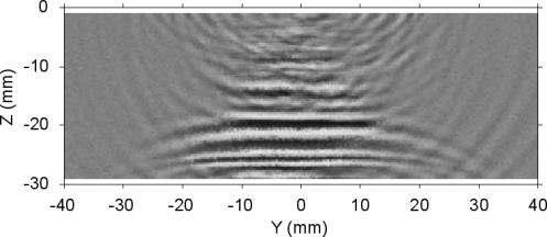
5 Instrumental visualization Computational visualization 5.3 μs hear hear hear hear 7.4 μs hear hear hear hear 10.3 μs hear hear Figure 6 Comparisons between the instrumental and computational visualization results (ide A) Instrumental visualization Computational visualization 5.7 μs hear hear hear hear 7.4 μs hear hear hear hear 10.1 μs hear hear Figure 7 Comparisons between the instrumental and computational visualization results (ide B)
6 Figure 6 shows the results when the scanned surface is parallel to ide A of the EMAT, while Figure 7 shows the results when the scanned surface is parallel to ide B of the EMAT. In these figures, the distributions at the same elapsed time after the emission of the ultrasonic for both visualization methods are horizontally aligned in each row. It is recognized that the longitudinal precede the shear in these images. When the longitudinal are reflected by the bottom surface, another group of shear occurs due to mode conversion. The propagation of the wave fronts of these longitudinal and shear can be observed in the images obtained by both visualization methods, though the images obtained by the instrumental visualization method include superfluous. As mentioned in ection 2, in the images for both visualization methods, the longitudinal are observed as circular from ide A, while these are observed as plane from ide B. The comparisons of these results show that the shapes of the wave fronts of the principal longitudinal and shear observed in the instrumental visualization results were well reproduced in the computational visualization results. 4. DIFFERET EMAT COFIGURATIO As an example of the application of the simulation procedure described in ection 3 for optimizing the configuration of an EMAT, this section shows the results of numerical simulations performed to seek an EMAT configuration that makes shear or longitudinal dominant. In Figs. 6 and 7, both longitudinal and shear can be clearly recognized. When only either one of the longitudinal and shear wave modes is utilized for inspection application, the other wave mode becomes noise and may deteriorate the R. Thus, eliminating unwanted is important to improve the R. In this section, the magnetic field and the distribution of the Lorentz force obtained in the numerical simulations are investigated to confirm how the configuration of an EMAT affects the generated ultrasonic. Figure 8 shows the magnetic field and the distribution of the Lorentz force obtained in the simulation with the EMAT configuration depicted in Fig. 2. The area displayed in these images is part of the central plane of the metal region that is parallel to ide A of the EMAT, while the EMAT is placed at the center of the top surface of the metal region. The origin of the coordinates is located at the intersection between the top surface of the metal region and the center axis of the EMAT. The vectors indicate the direction of the magnetic field or the Lorentz force at each point, and the colors represent their magnitude at that place. These images capture the moment that 0.6 μs elapse after the input pulse is triggered. The magnetic field remains almost unchanged throughout the time because the static magnetic field prevails. Although the magnitude of the Lorentz forces varies with time, the direction of the Lorentz forces does not change appreciably except a change in the opposite direction. Figure 8 illustrates that the two permanent magnets create an arc-shaped static magnetic field beneath the EMAT, the magnetic field has a dominant component in the horizontal direction around the center, and thus the Lorentz forces have a dominant component in the vertical direction around the center as shown in Fig. 3. This causes longitudinal as well as shear. Figure 9 shows the shape model of another EMAT configuration (hape model 2). Instead of a combination of two permanent magnets, a single permanent magnet is used to create a vertical magnetic field under the EMAT. This is confirmed in Fig. 10 (a), which shows the magnetic field due to the EMAT of a racetrack coil and a single permanent magnet. The magnetization vector of the magnet was set to 1 T in the vertical direction. Thus, the Lorentz forces have a dominant component in the horizontal direction as shown in Fig. 10 (b). Figure 11 shows the propagation of the ultrasonic generated by this EMAT at 5.5 μs after the emission of the ultrasonic. It is recognized that longitudinal are suppressed but still observed to some extent. Because the directions of the current flows are opposite between both sides of the loop of the coil, the directions of the eddy current flows are also opposite between the left-hand and right-hand sides in Fig. 10. Thus, the directions of the Lorentz forces become opposite between the left-hand and right-hand sides. This is thought to give rise to repeated compressive and tensile stresses at the center, which causes longitudinal.

 Figure 10 The simulation results")
7 (a) Magnetic field (T) (b) Distribution of the Lorentz force () Figure 8 The simulation results with the EMAT configuration depicted in Fig. 2 Figure 9 hape model 2 for EMolution (a) Magnetic field (T) (b) Distribution of the Lorentz force () Figure 10 The simulation results with hape model 2

8 hear Figure 11 Propagation of ultrasonic generated with hape model 2 Figure 12 shows the shape model of an EMAT using a one-way current flow (hape model 3). To avoid the Lorentz forces being reversed at the center, one-way currents are used for generation of ultrasonic. This is realized by using the straight-segment in only half part of a big racetrack coil. Because the cross-sectional area of the current path of this coil is doubled compared with the racetrack coil used in the former configurations, the number of turns in this coil was set to 80. The magnetic field created by this EMAT is almost the same as Fig. 10 (a). Figure 13 shows the distribution of the Lorentz force obtained with this EMAT. As intended, the Lorentz forces have a dominant component in the horizontal direction, and their directions are uniform at both sides. Figure 14 shows that this configuration makes shear dominant. However, longitudinal are still observed. ince the Lorentz force abruptly decreases away from under the utilized straight-segment of the coil, the region where the strong Lorentz force is exerted ends suddenly under both edges of the utilized straight-segment of the coil. This gives rise to repeated compressive and tensile stresses under these edges, which causes longitudinal, similarly to the EMAT shown in Fig. 9. This is supported by the fact that the longitudinal originate under these edges. By a similar notion, the horizontal magnetic field is supposed to make longitudinal dominant. Figure 15 shows the shape model of an EMAT using only half part of a big racetrack coil and a partial Halbach array of magnets (hape model 4). A 20 mm-cubed magnet is inserted between the pair of the magnets used in the first EMAT configuration to form a partial Halbach array. The magnetization vector of the center magnet was set to 1 T in the vertical direction. This array of magnets creates a relatively strong magnetic field along the bottom of the magnets as shown in Figs. 16 and 17 (a). Thus, the Lorentz forces have a dominant component in the vertical direction as shown in Fig. 17 (b). Figure 18 shows that this configuration makes longitudinal dominant. Figure 12 hape model 3 for EMolution Figure 13 Distribution of the Lorentz force () obtained with hape model 3

 Figure 17 The simulation results")
9 hear Figure 14 Propagation of ultrasonic generated with hape model 3 Z Y X Figure 15 hape model 4 for EMolution Magnetic field Figure 16 Magnet arrangement of hape model 4 (a) Magnetic field (T) (b) Distribution of the Lorentz force () Figure 17 The simulation results with hape model 4
10 hear Figure 18 Propagation of ultrasonic generated with hape model 4 5. UMMARY umerical simulations were performed to reproduce propagation of ultrasonic generated by several configurations of EMATs. The magnetic fields and the distributions of the Lorentz force obtained by the simulations were analyzed to seek an EMAT configuration that makes shear or longitudinal dominant and suppresses unnecessary components of the ultrasonic to be generated. The simulation results confirmed that the horizontal Lorentz forces generate shear, and the vertical Lorentz forces generate longitudinal. Because the Lorentz forces should be perpendicular to the magnetic field, the vertical or horizontal magnetic field makes shear or longitudinal dominant, respectively. In this manner, the distribution of the Lorentz force determines the wave mode of the ultrasonic to be generated, and analyzing the distribution of the Lorentz force provides help to design an EMAT configuration. Because the received signals are ultimately formed by the receiving process of an EMAT, suppressing the generation of unnecessary ultrasonic is only one aspect of the optimization of an EMAT configuration to improve the R of the received signals. To establish a complete optimization method, analysis of the receiving process of an EMAT is also required. REFERECE 1) Hirao M and Ogi H, EMATs for science and industry: oncontacting ultrasonic measurements, Boston/Dordrecht/London, Kluwer Academic Publishers, ) Yamamoto T, Furukawa T, Komura I, Urayama R, Uchimoto T and Takagi T, Property study on EMATs with visualization of ultrasonic propagation, M. Bieth (Ed.), Proceedings of the 10th International Conference on DE in Relation to tructural Integrity for uclear and Pressurized Components, European Union, 2014, ) Furukawa K, Yoneyama H, Horii Y and Uesugi, Measurement of ultrasonic wave propagation in austenitic stainless steel welds (I), F. Ammirato and. Otto-Rodgers (Ed.), Proceedings of the econd International Conference on DE in Relation to tructural Integrity for uclear and Pressurized Components, EPRI, 2000, B ) Urayama R, Uchimoto T and Takagi T, Application of EMAT/EC dual probe to monitoring of wall thinning in high temperature environment, International Journal of Applied Electromagnetics and Mechanics, 33(3 4), 2010,
PROPERTY STUDY ON EMATS WITH VISUALIZATION OF ULTRASONIC PROPAGATION
 More Info at Open Access Database www.ndt.net/?id=18576 PROPERTY STUDY ON EMATS WITH VISUALIZATION OF ULTRASONIC PROPAGATION T. Yamamoto, T. Furukawa, I. Komura Japan Power Engineering and Inspection Corporation,
A model for the ultrasonic field radiated by an Electro-Magnetic Acoustic Transducer in a ferromagnetic solid
 13th International Symposium on Nondestructive Characterization of Materials (NDCM-XIII), 2-24 May 213, Le Mans, France www.ndt.net/?id=1557 More Info at Open Access Database www.ndt.net/?id=1557 A model
Effect of Scaly Structure on the Measurement of Pipe Wall Thickness using EMAT
 E-Journal of Advanced Maintenance Vol.9-1 (2017) 15-25 Japan Society of Maintenology Effect of Scaly Structure on the Measurement of Pipe Wall Thickness using EMAT Hongjun SUN 1, Ryoichi URAYAMA 2, Tetsuya
Research on a Pattern of Pulse Electromagnetic Ultrasonic Generation
 Research on a Pattern of Pulse Electromagnetic Ultrasonic Generation LI Zhiyu, CHEN Peng, WANG Shuai, XU Aihua Ordnance Engineering College, Shi Jiazhuang, China e-mail: bryantzhi@16.com Abstract: Base
COMPARISON OF DEFECT DETECTION IN ALUMINUM AND STEEL PLATES USING AN ELECTROMAGNETIC ACOUSTIC TRANSDUCER
 The 12 th International Conference of the Slovenian Society for Non-Destructive Testing Application of Contemporary Non-Destructive Testing in Engineering September 4-6, 2013, Portorož, Slovenia COMPARISON
Electromagnetic Acoustic Transducers for In and Out of plane Ultrasonic Wave Detection
 7th World Conference on Nondestructive Testing, 5-8 Oct 8, Shanghai, China Electromagnetic Acoustic Transducers for In and Out of plane Ultrasonic Wave Detection Xiaoming JIAN, Steve DIXON, Karl QUIK Phoenix
Large Scale Computation of Coupled. Electro-Acoustic Systems using ANSYS and CAPA
 Large Scale Computation of Coupled Electro-Acoustic Systems using ANSYS and CAPA H.Landes, M. Kaltenbacher, R. Lerch Chair of Sensor Technology, University of Erlangen-Nürnberg Summary: The numerical simulation
Lecture 19. Measurement of Solid-Mechanical Quantities (Chapter 8) Measuring Strain Measuring Displacement Measuring Linear Velocity
 Measuring Strain Measuring Displacement Measuring Linear Velocity") MECH 373 Instrumentation and Measurements Lecture 19 Measurement of Solid-Mechanical Quantities (Chapter 8) Measuring Strain Measuring Displacement Measuring Linear Velocity Measuring Accepleration and
MECH 373 Instrumentation and Measurements Lecture 19 Measurement of Solid-Mechanical Quantities (Chapter 8) Measuring Strain Measuring Displacement Measuring Linear Velocity Measuring Accepleration and
STUDIES OF ELECTROMAGNETIC SOUND GENERATION FOR NDE* Thomas J. Moran Department of Physics Wayne State University Detroit, Michigan
 STUDES OF ELECTROMAGNETC SOUND GENERATON FOR NDE* NTRODUCTON Thomas J. Moran Department of Physics Wayne State University Detroit, Michigan This paper will first provide a brief review of the physics of
SIMULATION OF THE INSPECTION OF PLANAR NON MAGNETIC MATERIALS WITH ELECTRO MAGNETIC ACOUSTIC TRANSDUCERS
 SIMULATION OF THE INSPECTION OF PLANAR NON MAGNETIC MATERIALS WITH ELECTRO MAGNETIC ACOUSTIC TRANSDUCERS D. Prémel, C. Reboud, S. Chatillon, F. Reverdy and S. Mahaut CEA LIST, F-91191 Gif-sur-Yvette, France
SIMULATION OF THE INSPECTION OF PLANAR NON MAGNETIC MATERIALS WITH ELECTRO MAGNETIC ACOUSTIC TRANSDUCERS
 SIMULATION OF THE INSPECTION OF PLANAR NON MAGNETIC MATERIALS WITH ELECTRO MAGNETIC ACOUSTIC TRANSDUCERS Denis Prémel, C. Reboud, S. Chatillon, F. Reverdy and S. Mahaut CEA, LIST, Laboratoire Simulation
DEVELOPMENT OF A NON-CONTACTING STRESS MEASUREMENT SYSTEM DURING TENSILE TESTING USING THE ELECTROMAGNETIC ACOUSTIC TRANSDUCER FOR A LAMB WAVE
 DEVELOPMENT OF A NON-CONTACTING STRESS MEASUREMENT SYSTEM DURING TENSILE TESTING USING THE ELECTROMAGNETIC ACOUSTIC TRANSDUCER FOR A LAMB WAVE Riichi Murayama, Shinichi Tokunaga, Kouichi Hirata Fukuoka
Virtual Prototyping of Electrodynamic Loudspeakers by Utilizing a Finite Element Method
 Virtual Prototyping of Electrodynamic Loudspeakers by Utilizing a Finite Element Method R. Lerch a, M. Kaltenbacher a and M. Meiler b a Univ. Erlangen-Nuremberg, Dept. of Sensor Technology, Paul-Gordan-Str.
EDDY CURRENT TESTING
 EDDY CURRENT TESTING Introduction Eddy current inspection is a method that use the principal of electromagnetism as the basis for conducting examinations. Eddy Current NDT is a technique that can test
The initial magnetization curve shows the magnetic flux density that would result when an increasing magnetic field is applied to an initially
 MAGNETIC CIRCUITS The study of magnetic circuits is important in the study of energy systems since the operation of key components such as transformers and rotating machines (DC machines, induction machines,
Doppler echocardiography & Magnetic Resonance Imaging. Doppler echocardiography. History: - Langevin developed sonar.
 1 Doppler echocardiography & Magnetic Resonance Imaging History: - Langevin developed sonar. - 1940s development of pulse-echo. - 1950s development of mode A and B. - 1957 development of continuous wave
Finite element modeling of pulsed spiral coil Electromagnetic Acoustic Transducer (EMAT) for testing of plate
 for testing of plate") Finite element modeling of pulsed spiral coil Electromagnetic Acoustic Transducer (EMAT) for testing of plate R. Dhayalan, Anish Kumar, B. Purnachandra Rao and T. Jayakumar Ultrasonic Measurement Section
Finite element modeling of pulsed spiral coil Electromagnetic Acoustic Transducer (EMAT) for testing of plate R. Dhayalan, Anish Kumar, B. Purnachandra Rao and T. Jayakumar Ultrasonic Measurement Section
Revision Guide for Chapter 15
 Revision Guide for Chapter 15 Contents Revision Checklist Revision otes Transformer...4 Electromagnetic induction...4 Lenz's law...5 Generator...6 Electric motor...7 Magnetic field...9 Magnetic flux...
Development of a Compressor for a Miniature Pulse Tube Cryocooler of 2.5 W at 65 K
 Development of a Compressor for a Miniature Pulse Tube Cryocooler of 2.5 W at 65 K N. Matsumoto, Y. Yasukawa, K. Ohshima, T. Takeuchi, K. Yoshizawa, T. Matsushita, Y. Mizoguchi, and A. Ikura Fuji Electric
Surface Magnetic Non-Destructive Testing
 Surface Magnetic Non-Destructive Testing Evangelos Hristoforou 1,*, Konstantinos Kosmas 1 and Eleftherios Kayafas 2 1 School of Mining and Metallurgy Engineering, National Technical University of Athens,
Introduction. First Experiment
 Course : Bsc Applied Physical Science(Computer Science) IInd Year (Semester IV) Paper no : 14 Paper title : Electromagnetic Theory Lecture No : 14 Tittle : Faraday s Law of Induction Introduction Hello
VISUALIZATION OF SOUND PROPAGATION WITH ELECTRODYNAMIC PROBES
 VISUALIZATION OF SOUND PROPAGATION WITH ELECTRODYNAMIC PROBES Uwe VÖLZ, Heinz MRASEK, Klaus MATTHIES, Marc KREUTZBRUCK BAM Federal Institute for Materials Research and Testing, 12200 Berlin, Germany Abstract.
Non-contact evaluation of thickness reduction of plates and pipes using EMAT-generated guided wave
 IV Conferencia Panamericana de END Buenos Aires Octubre 7 Non-contact evaluation of thickness reduction of plates and pipes using EMAT-generated guided wave Ik-Keun Park, Yong-Kwon Kim and Jin-Hyuk Lee
Smart Pigs. Adrian Belanger March 7,
 Smart Pigs Adrian Belanger March 7, 2017 www.tdwilliamson.com Registered trademarks of T.D. Williamson, Inc. in the United States and in other countries. Copyright 2015 Oil and Gas Pipeline Network 2 Pipeline
The Acoustoelastic Effect: EMAT Excitation and Reception of Lamb Waves in Pre-Stressed Metal Sheets
 Excerpt from the Proceedings of the COMSOL Conference 2009 Milan The Acoustoelastic Effect: EMAT Excitation and Reception of Lamb Waves in Pre-Stressed Metal Sheets Riccardo M.G. Ferrari* 1 1 Danieli Automation
Chapter 27 Magnetism 1/20/ Magnets and Magnetic Fields Magnets and Magnetic Fields Magnets and Magnetic Fields
 Chapter 27 Magnetism Magnets have two ends poles called north and south. Like poles repel; unlike poles attract. However, if you cut a magnet in half, you don t get a north pole and a south pole you get
A Novel Sensor Design for Generation and Detection of Shear-Horizontal Waves Based on Piezoelectric Fibres
 11th European Conference on Non-Destructive Testing (ECNDT 2014), October 6-10, 2014, Prague, Czech Republic A Novel Sensor Design for Generation and Detection of Shear-Horizontal Waves Based on Piezoelectric
MAGNETIC PROBLEMS. (d) Sketch B as a function of d clearly showing the value for maximum value of B.
 Sketch B as a function of d clearly showing the value for maximum value of B.") PHYS2012/2912 MAGNETC PROBLEMS M014 You can investigate the behaviour of a toroidal (dough nut shape) electromagnet by changing the core material (magnetic susceptibility m ) and the length d of the air
PHYS2012/2912 MAGNETC PROBLEMS M014 You can investigate the behaviour of a toroidal (dough nut shape) electromagnet by changing the core material (magnetic susceptibility m ) and the length d of the air
SHM with EMATs. Julio ISLA-GARCIA 1, Balint HERDOVICS 1, Frederic CEGLA 1
 8th European Workshop On Structural Health Monitoring (EWSHM 2016), 5-8 July 2016, Spain, Bilbao www.ndt.net/app.ewshm2016 SHM with EMATs Julio ISLA-GARCIA 1, Balint HERDOVICS 1, Frederic CEGLA 1 More
Measurements in Optics for Civil Engineers
 Measurements in Optics for Civil Engineers I. FOCAL LENGTH OF LENSES The behavior of simplest optical devices can be described by the method of geometrical optics. For convex or converging and concave
Strain Measurement. Prof. Yu Qiao. Department of Structural Engineering, UCSD. Strain Measurement
 Strain Measurement Prof. Yu Qiao Department of Structural Engineering, UCSD Strain Measurement The design of load-carrying components for machines and structures requires information about the distribution
Electromagnetic Testing (ET)
") Electromagnetic Testing Electromagnetic testing is a general test category that includes Eddy Current testing (ECT), Alternating Current Field Measurement (ACFM) and Remote Field testing. All of these
Electromagnetic Testing Electromagnetic testing is a general test category that includes Eddy Current testing (ECT), Alternating Current Field Measurement (ACFM) and Remote Field testing. All of these
Revision Guide for Chapter 15
 Revision Guide for Chapter 15 Contents tudent s Checklist Revision otes Transformer... 4 Electromagnetic induction... 4 Generator... 5 Electric motor... 6 Magnetic field... 8 Magnetic flux... 9 Force on
GCSE PHYSICS REVISION LIST
 GCSE PHYSICS REVISION LIST OCR Gateway Physics (J249) from 2016 Topic P1: Matter P1.1 Describe how and why the atomic model has changed over time Describe the structure of the atom and discuss the charges
Version The diagram below represents lines of magnetic flux within a region of space.
 1. The diagram below represents lines of magnetic flux within a region of space. 5. The diagram below shows an electromagnet made from a nail, a coil of insulated wire, and a battery. The magnetic field
Practical Results of Ultrasonic Imaging by Inverse Wave Field Extrapolation
 ECNDT 2006 - Th.2.3.1 Practical Results of Ultrasonic Imaging by Inverse Wave Field Extrapolation Niels PÖRTZGEN, RTD Group, Rotterdam, The Netherlands Abstract: Array technology in non-destructive inspection
NDT&E Methods: UT Ultrasound Generation
 CAVITY INSPECTION NDT&E Methods: UT Ultrasound Generation VJ Technologies NDT&E Methods: UT 6. NDT&E: Introduction to Methods 6.1. Ultrasonic Testing: Basics of Elasto-Dynamics 6.2. Ultrasonic Testing:
Physics 9e/Cutnell. correlated to the. College Board AP Physics 2 Course Objectives
 correlated to the College Board AP Physics 2 Course Objectives Big Idea 1: Objects and systems have properties such as mass and charge. Systems may have internal structure. Enduring Understanding 1.A:
Chapter 27 Magnetism. Copyright 2009 Pearson Education, Inc.
 Chapter 27 Magnetism 27-1 Magnets and Magnetic Fields Magnets have two ends poles called north and south. Like poles repel; unlike poles attract. 27-1 Magnets and Magnetic Fields However, if you cut a
Pulse eddy currents using an integral-fem formulation for cracks detection
 International Journal of Applied Electromagnetics and Mechanics 33 (2010) 1225 1229 1225 DOI 10.3233/JAE-2010-1242 IOS Press Pulse eddy currents using an integral-fem formulation for cracks detection Gabriel
ULTRASONIC CHARACTERIZATION OF RESIDUAL STRESS AND TEXTURE IN CAST STEEL RAILROAD WHEELS
 ULTRASONC CHARACTERZATON OF RESDUAL STRESS AND TEXTURE N CAST STEEL RALROAD WHEELS A. v. Clark, H. Fukuoka*, D. V. Mitrakovic** and J, C. Moulder Fracture and Deformation Division National Bureau of Standards
Measurement Techniques for Engineers. Motion and Vibration Measurement
 Measurement Techniques for Engineers Motion and Vibration Measurement Introduction Quantities that may need to be measured are velocity, acceleration and vibration amplitude Quantities useful in predicting
NEW SOUTH WALES DEPARTMENT OF EDUCATION AND TRAINING Manufacturing and Engineering ESD. Sample Examination EA605
 Name: NEW SOUTH WALES DEPARTMENT OF EDUCATION AND TRAINING Manufacturing and Engineering ESD Sample Examination EA605 EDDY CURRENT TESTING AS3998 LEVEL 2 GENERAL EXAMINATION 6161C * * * * * * * Time allowed
Detection of Wear in Oilwell Service Tubings using Magnetic Flux Leakage
 Detection of Wear in Oilwell Service Tubings using Magnetic Flux Leakage Many methods have been developed and used for the inspection of oilwell service tubings to find wear, corrosion and fractures. One
Electricity & Magnetism Study Questions for the Spring 2018 Department Exam December 4, 2017
 Electricity & Magnetism Study Questions for the Spring 2018 Department Exam December 4, 2017 1. a. Find the capacitance of a spherical capacitor with inner radius l i and outer radius l 0 filled with dielectric
Finite Element Modeling of Ultrasonic Transducers for Polymer Characterization
 Excerpt from the Proceedings of the COMSOL Conference 2009 Milan Finite Element Modeling of Ultrasonic Transducers for Polymer Characterization Serena De Paolis *, Francesca Lionetto and Alfonso Maffezzoli
4 Finite Element Analysis of a three-phase PM synchronous machine
 Assignment 4 1-1 4 Finite Element Analysis of a three-phase PM synchronous machine The goal of the third assignment is to extend your understanding on electromagnetic analysis in FEM. This assignment is
Magnetostatics III. P.Ravindran, PHY041: Electricity & Magnetism 1 January 2013: Magntostatics
 Magnetostatics III Magnetization All magnetic phenomena are due to motion of the electric charges present in that material. A piece of magnetic material on an atomic scale have tiny currents due to electrons
Analysis of the Impact of Major Influencing Factors on the Waveform of the Surface Eddy Current Probe for Electroconductive Nonmagnetic Pipe Thickness
 Journal of Physics: Conference Series PAPER OPEN ACCESS Analysis of the Impact of Major Influencing Factors on the Waveform of the Surface Eddy Current Probe for Electroconductive Nonmagnetic Pipe Thickness
Optimization of the Bias Magnetic Field of Shear Wave EMATs Julio Isla and Frederic Cegla
 1148 IEEE TRANSACTIONS ON ULTRASONICS, FERROELECTRICS, AND FREQUENCY CONTROL, VOL. 63, NO. 8, AUGUST 2016 Optimization of the Bias Magnetic Field of Shear Wave EMATs Julio Isla and Frederic Cegla Abstract
Sound Waves. Sound waves are longitudinal waves traveling through a medium Sound waves are produced from vibrating objects.
 Sound Waves Sound waves are longitudinal waves traveling through a medium Sound waves are produced from vibrating objects Introduction Sound Waves: Molecular View When sound travels through a medium, there
Electromagnetic Forming Process Analysis Based on Coupled Simulations of Electromagnetic Analysis and Structural Analysis
 Journal of Magnetics 21(2), 215-221 (2016) ISSN (Print) 1226-1750 ISSN (Online) 2233-6656 http://dx.doi.org/10.4283/jmag.2016.21.2.215 Electromagnetic Forming Process Analysis Based on Coupled Simulations
Two point charges, A and B, lie along a line separated by a distance L. The point x is the midpoint of their separation.
 Use the following to answer question 1. Two point charges, A and B, lie along a line separated by a distance L. The point x is the midpoint of their separation. 1. Which combination of charges would yield
CHAPTER 4 BASICS OF ULTRASONIC MEASUREMENT AND ANFIS MODELLING
 37 CHAPTER 4 BASICS OF ULTRASONIC MEASUREMENT AND ANFIS MODELLING 4.1 BASICS OF ULTRASONIC MEASUREMENT All sound waves, whether audible or ultrasonic, are mechanical vibrations involving movement in the
Numerical Simulation in Alternating Current Field Measurement
 19 th World Conference on Non-Destructive Testing 2016 Numerical Simulation in Alternating Current Field Measurement Wenpei ZHENG 1 1 China University of Petroleum-Beijing, Beijing, China Contact e-mail:
ANALYSIS OF FREQUENCY CHARACTERISTICS ON NON-INVASIVE ULTRASONIC-DOPPLER FLOW MEASUREMENT FOR METAL PIPES
 4th International Symposium on Ultrasonic Doppler Method for Fluid Mechanics and Fluid Engineering Sapporo, 6.-8. September, 2004 ANALYSIS OF FREQUENCY CHARACTERISTICS ON NON-INVASIVE ULTRASONIC-DOPPLER
MAGNETISM. Magnetism. Magnetism is a result of electrons spinning on their own axis around the nucleus (Figure 18). Basic Electrical Theory
. Basic Electrical Theory") Basic Electrical Theory Certain metals and metallic oxides have the ability to attract other metals. This property is called magnetism, and the materials which have this property are called magnets. Some
Basic Electrical Theory Certain metals and metallic oxides have the ability to attract other metals. This property is called magnetism, and the materials which have this property are called magnets. Some
Topic 6.3 Magnetic Force and Field. 2 hours
 Topic 6.3 Magnetic Force and Field 2 hours 1 Magnetic Fields A magnetic field is said to exist at a point if a compass needle placed there experiences a force. The appearance of a magnetic field can be
THE DETECTION OF MAGNETIC PHASE TRANSITIONS IN ER-TM BY. C M Lim, S Dixon, C Edwards and S B Palmer.
 THE DETECTION OF MAGNETIC PHASE TRANSITIONS IN ER-TM BY ELECTROMAGNETIC ACOUSTIC TRANSDUCERS C M Lim, S Dixon, C Edwards and S B Palmer. Department of Physics University of Warwick Coventry CV 4 7 AL,
Chapter 30 Sources of the magnetic field
 Chapter 30 Sources of the magnetic field Force Equation Point Object Force Point Object Field Differential Field Is db radial? Does db have 1/r2 dependence? Biot-Savart Law Set-Up The magnetic field is
N. Shaikh, C. Steele and G.S. Kino
 ACOUSTOELASTICITY: SCANNING WITH SHEAR WAVES N. Shaikh, C. Steele and G.S. Kino Edward L. Ginzton Laboratory Stanford University Stanford, CA 94305 ABSTRACT Acoustoelasticity is a promlslng method for
week 8 The Magnetic Field
 week 8 The Magnetic Field General Principles General Principles Applications Start with magnetic forces on moving charges and currents A positive charge enters a uniform magnetic field as shown. What is
INTRODUCTION MAGNETIC FIELD OF A MOVING POINT CHARGE. Introduction. Magnetic field due to a moving point charge. Units.
 Chapter 9 THE MAGNETC FELD ntroduction Magnetic field due to a moving point charge Units Biot-Savart Law Gauss s Law for magnetism Ampère s Law Maxwell s equations for statics Summary NTRODUCTON Last lecture
APPLICATION OF THE FINITE ELEMENT METHOD TO MODEL THE NONLINEAR VOICE COIL MOTION PRODUCED BY A LOUDSPEAKER MAGNET ASSEMBLY.
 APPLICATION OF THE FINITE ELEMENT METHOD TO MODEL THE NONLINEAR VOICE COIL MOTION PRODUCED BY A LOUDSPEAKER MAGNET ASSEMBLY. Mark Dodd Celestion International & KEF Audio (UK) Ltd. 1. INTRODUCTION Moving
MAGNETIC FIELDS & UNIFORM PLANE WAVES
 MAGNETIC FIELDS & UNIFORM PLANE WAVES Name Section Multiple Choice 1. (8 Pts) 2. (8 Pts) 3. (8 Pts) 4. (8 Pts) 5. (8 Pts) Notes: 1. In the multiple choice questions, each question may have more than one
APPLICATION-DIRECTED MODELING OF RADIATION AND PROPAGATION OF ELASTIC WAVES IN ANISOTROPIC MEDIA: GPSS AND OPOSSM
 APPLICATION-DIRECTED MODELING OF RADIATION AND PROPAGATION OF ELASTIC WAVES IN ANISOTROPIC MEDIA: GPSS AND OPOSSM M. Spies, F. Walte Fraunhofer-Institute for Nondestructive Testing (IzfP) 66123 Saarbriicken,
Lecture Sound Waves Review. Physics Help Q&A: tutor.leiacademy.org. Force on a Charge Moving in a Magnetic Field
 Lecture 1101 Sound Waves Review Physics Help Q&A: tutor.leiacademy.org Force on a Charge Moving in a Magnetic Field A charge moving in a magnetic field can have a magnetic force exerted by the B-field.
Physics 102: Magnetic Fields
 Physics 102: Magnetic Fields Assist. Prof. Dr. Ali Övgün EMU Physics Department www.aovgun.com Electric Field & Magnetic Field Electric forces acting at a distance through electric field. Vector field,
Operation of an Electromagnetic Trigger with a Short-circuit Ring
 Operation of an Electromagnetic Trigger with a Short-circuit Ring Dejan Križaj 1*, Zumret Topčagić 1, and Borut Drnovšek 1,2 1 Faculty of Electrical Engineering, University of Ljubljana, Ljubljana, Slovenia,
Ultrasonic Measurement of Minute Displacement of Object Cyclically Actuated by Acoustic Radiation Force
 Jpn. J. Appl. Phys. Vol. 42 (2003) pp. 4608 4612 Part 1, No. 7A, July 2003 #2003 The Japan Society of Applied Physics Ultrasonic Measurement of Minute Displacement of Object Cyclically Actuated by Acoustic
Lamb Waves in Plate Girder Geometries
 Lamb Waves in Plate Girder Geometries D.W. Greve, 1 N. L. Tyson 2, and I.J. Oppenheim 2 1 Electrical and Computer Engineering, Carnegie Mellon University, Pittsburgh, PA, 15213 2 Civil and Environmental
Chapter 27 Magnetism. Copyright 2009 Pearson Education, Inc.
 Chapter 27 Magnetism 27-1 Magnets and Magnetic Fields Magnets have two ends poles called north and south. Like poles repel; unlike poles attract. 27-1 Magnets and Magnetic Fields However, if you cut a
LECTURE 22 MAGNETIC TORQUE & MAGNETIC FIELDS. Instructor: Kazumi Tolich
 LECTURE 22 MAGNETIC TORQUE & MAGNETIC FIELDS Instructor: Kazumi Tolich Lecture 22 2! Reading chapter 22.5 to 22.7! Magnetic torque on current loops! Magnetic field due to current! Ampere s law! Current
Physics 12. Unit 8 Magnetic Field and Electromagnetism Part I
 Physics 12 Unit 8 Magnetic Field and Electromagnetism Part I 1. Basics about magnets Magnets have been known by ancient people since long time ago, referring to the iron-rich rocks, called magnetite or
Electrodynamic passive magnetic bearing using reluctance forces
 Electrodynamic passive magnetic bearing using reluctance forces Keywords Jan Sandtner, Hannes Bleuler: École polytechnique fédérale de Lausanne EPFL, Switzerland Département de microtechnique DMT, Institut
A little history. Electricity and Magnetism are related!
 Intro to Magnetism A little history Until the early 19 th century, scientists thought electricity and magnetism were unrelated In 1820, Danish science professor Hans Christian Oersted was demonstrating
AN ULTRA-HIGH RESOLUTION PULSED-WIRE MAGNET MEASUREMENT SYSTEM. Alex D Audney Thesis Defense Colorado State University
 AN ULTRA-HIGH RESOLUTION PULSED-WIRE MAGNET MEASUREMENT SYSTEM Alex D Audney Thesis Defense Colorado State University 1 Overview Introduction and Background Pulsed-Wire Method Overview The CSU Undulator
Unit Packet Table of Contents Notes 1: Magnetism Intro Notes 2: Electromagnets Notes 3: Electromagnetic Induction Guided Practice: Left Hand Rule #3
 Unit Packet Table of Contents Notes 1: Magnetism Intro Notes 2: Electromagnets Notes 3: Electromagnetic Induction Guided Practice: Left Hand Rule #3 Name Date Notes: Magnetism intro. Regents Physics Objectives:
The Direction of Magnetic Field. Neil Alberding (SFU Physics) Physics 121: Optics, Electricity & Magnetism Spring / 16
 Physics 121: Optics, Electricity & Magnetism Spring / 16") The Direction of Magnetic Field Neil Alberding (SFU Physics) Physics 121: Optics, Electricity & Magnetism Spring 2010 1 / 16 The Magnetic Field We introduced electric field to explain-away long-range electric
The Direction of Magnetic Field Neil Alberding (SFU Physics) Physics 121: Optics, Electricity & Magnetism Spring 2010 1 / 16 The Magnetic Field We introduced electric field to explain-away long-range electric
LECTURE NO. 4-5 INTRODUCTION ULTRASONIC * PULSE VELOCITY METHODS
 LECTURE NO. 4-5 ULTRASONIC * PULSE VELOCITY METHODS Objectives: To introduce the UPV methods To briefly explain the theory of pulse propagation through concrete To explain equipments, procedures, calibrations,
4. An electron moving in the positive x direction experiences a magnetic force in the positive z direction. If B x
 Magnetic Fields 3. A particle (q = 4.0 µc, m = 5.0 mg) moves in a uniform magnetic field with a velocity having a magnitude of 2.0 km/s and a direction that is 50 away from that of the magnetic field.
Physics Project. Name:- Dabhi Mihir Roll No:- 3 Class:- 12 th (Science-PCB) Topic:- Moving coil galvanometer
 Topic:- Moving coil galvanometer") Physics Project Name:- Dabhi Mihir Roll No:- 3 Class:- 12 th (Science-PCB) Topic:- Moving coil galvanometer M o v i n g C o i l G a l v a n o m e t e r - P h y s i c s P r o j e c t Page 1 Certificate:-
Physics Project Name:- Dabhi Mihir Roll No:- 3 Class:- 12 th (Science-PCB) Topic:- Moving coil galvanometer M o v i n g C o i l G a l v a n o m e t e r - P h y s i c s P r o j e c t Page 1 Certificate:-
Class XII- Physics - Assignment Topic: - Magnetic Effect of Current
 LJPS Gurgaon 1. An electron beam projected along +X axis, experiences a force due to a magnetic field along +Y axis. What is the direction of the magnetic field? Class XII- Physics - Assignment Topic:
Reactor Characteristic Evaluation and Analysis Technologies of JFE Steel
 JFE TECHNICAL REPORT No. 21 (Mar. 2016) Reactor Characteristic Evaluation and Analysis Technologies of HIRATANI Tatsuhiko *1 NAMIKAWA Misao *2 NISHINA Yoshiaki *3 Abstract: Reactor characteristic evaluation
ULTRASONIC WAVE PROPAGATION IN DISSIMILAR METAL WELDS APPLICATION OF A RAY-BASED MODEL AND COMPARISON WITH EXPERIMENTAL RESULTS
 ULTRASONIC WAVE PROPAGATION IN DISSIMILAR METAL WELDS APPLICATION OF A RAY-BASED MODEL AND COMPARISON WITH EXPERIMENTAL RESULTS Audrey GARDAHAUT 1, Hugues LOURME 1, Frédéric JENSON 1, Shan LIN 2, Masaki
Generation and Analyses of Guided Waves in Planar Structures
 Engineering, 011, 3, 53-537 doi:10.436/eng.011.3506 Published Online May 011 (http://www.scirp.org/journal/eng) Generation and Analyses of Guided Waves in Planar Structures Abstract Enkelejda Sotja 1,
AP Physics Electromagnetic Wrap Up
 AP Physics Electromagnetic Wrap Up Here are the glorious equations for this wonderful section. This is the equation for the magnetic force acting on a moving charged particle in a magnetic field. The angle
Chapter 30. Sources of the Magnetic Field Amperes and Biot-Savart Laws
 Chapter 30 Sources of the Magnetic Field Amperes and Biot-Savart Laws F B on a Charge Moving in a Magnetic Field Magnitude proportional to charge and speed of the particle Direction depends on the velocity
Induction Heating: fundamentals
 LEP ELECTROMAGNETIC PROCESSING OF MATERIALS TECNOLGIE DEI PROCESSI ELETTROTERMICI Induction Heating: fundamentals Fabrizio Dughiero 2017-2018 Induction heating fundamentals May 28-30, 2014 1 Summary 1.
4. What is the speed (in cm s - 1 ) of the tip of the minute hand?
 of the tip of the minute hand?") Topic 4 Waves PROBLEM SET Formative Assessment NAME: TEAM: THIS IS A PRACTICE ASSESSMENT. Show formulas, substitutions, answers, and units! Topic 4.1 Oscillations A mass is attached to a horizontal spring.
Topic 4 Waves PROBLEM SET Formative Assessment NAME: TEAM: THIS IS A PRACTICE ASSESSMENT. Show formulas, substitutions, answers, and units! Topic 4.1 Oscillations A mass is attached to a horizontal spring.
Investigation of Eddy Current Nondestructive Testing for Carbon Fiber-Reinforced Plastic (CFRP) Based on Electromagnetic Field Analysis
 Based on Electromagnetic Field Analysis") Journal of Mechanics Engineering and Automation 8 (2018) 127-131 doi: 10.17265/2159-5275/2018.03.004 D DAVID PUBLISHING Investigation of Eddy Current Nondestructive Testing for Carbon Fiber-Reinforced
Journal of Mechanics Engineering and Automation 8 (2018) 127-131 doi: 10.17265/2159-5275/2018.03.004 D DAVID PUBLISHING Investigation of Eddy Current Nondestructive Testing for Carbon Fiber-Reinforced
PHYSICS. Chapter 16 Lecture FOR SCIENTISTS AND ENGINEERS A STRATEGIC APPROACH 4/E RANDALL D. KNIGHT Pearson Education, Inc.
 PHYSICS FOR SCIENTISTS AND ENGINEERS A STRATEGIC APPROACH 4/E Chapter 16 Lecture RANDALL D. KNIGHT 2017 Pearson Education, Inc. Chapter 16 Traveling Waves IN THIS CHAPTER, you will learn the basic properties
Chapter 27, 28 & 29: Magnetism & Electromagnetic Induction
 Chapter 27, 28 & 29: Magnetism & Electromagnetic Induction The Magnetic Field The Magnetic Force on Moving Charges The Motion of Charged Particles in a Magnetic Field The Magnetic Force Exerted on a Current-Carrying
Chapter 11. Vibrations and Waves
 Chapter 11 Vibrations and Waves Driven Harmonic Motion and Resonance RESONANCE Resonance is the condition in which a time-dependent force can transmit large amounts of energy to an oscillating object,
Final Exam Physics 7b Section 2 Fall 2004 R Packard. Section Number:
 Final Exam Physics 7b Section 2 Fall 2004 R Packard Name: SID: Section Number: The relative weight of each problem is stated next to the problem. Work the easier ones first. Define physical quantities
Chapter 22, Magnetism. Magnets
 Chapter 22, Magnetism Magnets Poles of a magnet (north and south ) are the ends where objects are most strongly attracted. Like poles repel each other and unlike poles attract each other Magnetic poles
Impedance Evaluation of a Probe-Coil s Lift-off and Tilt Effect in Eddy-Current Nondestructive Inspection by 3D Finite Element Modeling
 17th World Conference on Nondestructive Testing, 25-28 Oct 28, Shanghai, China Impedance Evaluation of a Probe-Coil s Lift-off and Tilt Effect in Eddy-Current Nondestructive Inspection by 3D Finite Element
MAGNETIC CIRCUITS, MOTOR AND GENERATOR ACTION
 Topic 3 MAGNETIC CIRCUITS, MOTOR AND GENERATOR ACTION Magnetic Flux SI unit, Webers (Wb) ϕ Flows from North to South Pole 1 Magnetic Flux Density Measure of Flux/Area SI units, Wb/m 2 = Tesla, B Think
Equal Pitch and Unequal Pitch:
 Equal Pitch and Unequal Pitch: Equal-Pitch Multiple-Stack Stepper: For each rotor stack, there is a toothed stator segment around it, whose pitch angle is identical to that of the rotor (θs = θr). A stator
Experiment 5: Measurements Magnetic Fields
 Experiment 5: Measurements Magnetic Fields Introduction In this laboratory you will use fundamental electromagnetic Equations and principles to measure the magnetic fields of two magnets. 1 Physics 1.1