Opto-mechanical analysis and design tool for adaptive X-ray optics
|
|
|
- Aleesha Lamb
- 5 years ago
- Views:
Transcription
1 Opto-mechanical analysis and design tool for adaptive X-ray optics Gregory Michels, Victor Genberg Sigmadyne, Inc. 803 West Ave, Rochester, Y michels@sigmadyne.com ABSTRACT Adaptive X-ray optics offer significant potential for new optical systems. An analysis and design tool for the optomechanical design of adaptive X-ray optics is presented. The key issues addressed are: 1) The processing of finite element nodal displacements for optical surface characterization is illustrated. 2) The fitting of Fourier-Legendre polynomials to the radial sag or surface normal displacements of near cylindrical optics is presented. 3) The use of 2D Legendre polynomials are presented as an alternative representation of mechanical displacements. 4) The analysis of adaptive X-ray optics requires the solution of actuator strokes required to minimize surface RMS. Issues include stroke limits and surface slope error minimization. 5) The number and placement of actuators can be optimized by using an embedded genetic selection algorithm. 6) The mirror structure and mounts may be optimized to minimize the adaptively corrected surface error while still satisfying all structural requirements. 7) The implementation of a Monte Carlo technique to predict the impact of random factors in the system such as actuator resolution or mount strain forces. Keywords: finite element, Fourier-Legendre, Legendre, adaptive, optimization, opto-mechanic, X-ray 1. ITRODUCTIO The design challenges to develop grazing incidence X-ray optics for modern systems such as the International X-Ray Observatory (IXO) are well known to be daunting. 1 The ability to characterize results from mechanical analysis software tools and to transfer those characterizations to optical analysis software tools was a valuable asset to the design development of the Chandra X-Ray Observatory. 2 A flow chart of this analysis process is shown in Figure 1. SigFit is a commercial software tool from Sigmadyne which is used in the integrated opto-mechanical analysis of optical systems as shown in Figure 1. 3,4 While SigFit has been in practice for the development of normal incidence optics, recent enhancements have been added to allow analysis of grazing incidence optics such as those used in X-ray astronomy. This paper discusses the methods and capabilities implemented in SigFit specifically with regard to passive and adaptively controlled grazing incidence optics. Thermal Analysis Interpolated Temperatures Structural Analysis Temperatures Displacements Stresses Optical Testing Test Data SigFit Design Optimization Entries Result Files Printed Summaries Optical Analysis Figure 1. Opto-mechanic analysis flow
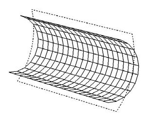
2 2. PROCESSIG OF FIITE ELEMET DISPLACEMETS In order to describe the deformed shape of a cylindrical optic as predicted by finite element analysis (FEA), the nodal displacement vectors must be processed into a form useable to describe the deformed shape. Figure 2 illustrates a deformed cylindrical optic with an undeformed node P and a corresponding displaced node P' as predicted by analysis such as FEA. In addition, the normal deformation and radial deformations of the original location P are shown as labeled. otice that the displacement vector given by PP' is neither the normal nor the radial sag displacement of the deformed optic. The desired normal or radial sag deformations, which are the deformations commonly employed for the purposes of describing the deformed shape of the optical surface, must be computed from the displacement vector given by PP'. deformed shape undeformed shape normal deformation P displaced node position P original node position radial sag deformation Figure 2. Illustration of normal and radial deformation relative to the displaced node position as represented by FEA results. It can be shown that the normal deformation of the optic can be approximated to first order by simply taking the component of the FEA nodal displacement vector in the direction of the surface normal. The first order approximation of the radial sag deformation is somewhat more complicated as it involves the first derivative of the radial sag of the surface prescription with respect to the axial coordinate. The process of converting the FEA nodal displacement into the radial sag deformation is called axial correction as it incorporates the effect of axial displacement on the radial sag. While the method described in Figure 2 ignores the effect of azimuthal displacements, a generalization can be made to account for all three nodal translations predicted by FEA. In the case of axisymmetric optics, the effect of azimuthal displacement on the radial sag is generally of lower order than the effect of axial displacements. The need for axial correction is shown in the following example where an optic with a kinematic mount midway between the upper and lower edges is subjected to an isothermal temperature increase. The low order deformation terms of average radial growth and cone have been subtracted. The most significant remaining deformation of barrel shows an opposite sign with and without axial correction and is shown in Figure 3. This is illustrating that axial displacement causes an effective radial displacement and neglecting it leads to erroneous results. The correction is, therefore, especially important with thermoelastic loads, which tend to have high axial growth compared to radial growth due to the nature of the geometry.
3 (a) Figure 3. Deformed plots of only radial deformation illustrating barrel distortion (a) without axial correction and (b) with axial correction. 3. FOURIER-LEGEDRE POLYOMIALS The use of Fourier-Legendre polynomials 5 is a common means to quantify the deformed shape of a cylindrical optic. Fourier-Legendre polynomials are defined by Equation 1 where n is the axial wave number and m is the circumferential wave number. f ( z, Θ) = P n M Pn ( z) [ Anm cos( mθ) + Bnm sin( mθ) ] (1a) n= 0 m= 0 K k ( 2n 2k)! n 2k = z (1b) n k = 0 2 k! ( n k)(! n 2)! ( z) ( 1) Plots of several low-order polynomials appear in Appendix A. Fourier-Legendre polynomials (FLG) are similar to Zernike polynomials (ZR) in several ways. 1. n = axial wave number in FLG, n = radial wave number in ZR. 2. m = radial wave number in both FLG and ZR. 3. Both FLG and ZR form an orthogonal set. FLG are orthogonal over the full cylindrical aperture of -1 < z < +1 while ZR are orthogonal over a circle of unit radius. 4. Both FLG and ZR may be normalized to unit amplitude or unit RMS. 5. Both may be fit to normal or sag displacement. Sag for FLG is radial displacement while sag displacement for ZR is axial displacement. See Figure 2 for an illustration of radial sag displacement. (b) The coefficients of the Fourier-Legendre polynomial fit may then be used as input to an optical analysis model to allow optical performance predictions of the optic. 4. LEGEDRE POLYOMIALS FOR SEGMETED OPTICS For segmented cylindrical optics, the deformation in each segment may be independent of other panels. Polynomials continuous over the full cylinder, such as FLG, will not represent a good fit to deformation data as they will not be able to capture the discontinuities introduced by the separate segments. Legendre polynomials 5 (LEG), on the other hand, may be defined over a single cylindrical segment. Plots of low order LEG polynomials appear in Appendix B. LEG polynomials are similar to XY polynomials for conventional optics, except that: 1. LEG form an orthogonal set, whereas XY do not. 2. LEG may have an independent normalization for each domain variable. XY have a single normalization used for both domain variables.
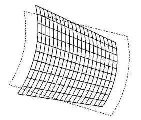
4 When applied to grazing incidence optics, LEG are fit with respect to the axial (Z) and circumferential (Θ) directions with an independent normalization of each. The user may choose to fit surface normal (s = dn) or radial sag (s = dr) deformation. P n M s = cnmpn ( z) Pm ( Θ) (2a) n= 0 m= 0 K k K k ( 2n 2k)! n 2k ( ) ( ) ( 2m 2k)! m 2k z P n n Θ = 1 Θ (2b) m k = 0 2 k! ( n k)(! n 2 )! k = 0 2 k! ( m k)(! m 2)! ( z) ( 1) = In Figure 4 a segmented optic and a continuous optic with a circumferential gradient are compared. When the continuous optic is fit with Fourier-Legendre polynomials through order (n=6, m=6), 99.7% of deformation is represented. If the same fit is applied to the segmented optic, only 94.4% of the deformation is represented, missing 5.6%. When Legendre polynomials through order (n=6, m=6) are applied independently to each segment, the fit represents 99.98% of the deformation, missing only 0.02%. (a) Figure 4. Deformation due to circumferential thermal gradient for (a) continuous optic and (b) a 6-panel segmented optic. The coefficients of the Legendre polynomial fit may then be used as input to an optical analysis model to allow optical performance predictions of the optic. 5. AALYSIS OF ADAPTIVE X-RAY OPTICS SigFit s adaptive analysis capability will solve for the actuator amplitudes required to minimize the surface error. 6 Actuator influence functions may be supplied through FEA results in the same manner as the disturbances to be corrected. Actuators included in adaptive control simulation may, therefore, be force or displacement type, either external or embedded within the optic or any influence that may be simulated in FEA and is linearly related to its controlling input, A. The actuator inputs for best correction of the optical surface are computed by minimization of the mean square error function defined as, (b)
5 where, E = w ds' M i i i= 1 j= 1 = the number of nodes, w i = weighting coefficient of node i, M = the number of actuator influence functions, ds i = surface deformation at node i, (radial or normal) A j = actuator input for actuator influence function j, f ji = surface deformation of actuator influence function j at node i. A j f ji 2 (3) Taking partial derivatives of E with respect to each actuator input and setting each equal to zero leads to a linear system of M equations for M unknowns, [ H ]{ C} = { F}, (4a) H jk = wi f ji fki, (4b) i F k = wids' i fki, (4c) i which allows for computation of the actuator inputs which minimize the error E. SigFit also offers an option to include slopes along with sag or surface normal translations in the minimization of surface RMS. The user input is a slope fraction, c, whose value ranges from 0.0 (no slopes included) to 1.0 (no translations included). Since displacements and slopes are in different units, slopes must be converted to displacement units. To convert radians to displacement units, SigFit multiplies the slopes by the average node spacing, L. In SigFit, L is calculated from the optic surface area, a, and the number of nodes on the surface,. a L = (5) Let Θ i = x-slope at node i and Φ i = y-slope at node i, then the combined error to be minimized is: E = (1 c) w ds' M i i i= 1 j= 1 A f j ji 2 + ( c)( L) w dθ' M i i i= 1 j= 1 A Θ j ji 2 + ( c)( L) w dφ' M i i i= 1 j= 1 ote that using slope data in the fit is only valid if the FE model predicts meaningful slope data. Solid finite element models, for example, generally do not generate slope data. Shell elements are often required to create valid slope output. In adaptive analysis, the user may specify limits on actuator motion or force level. If selected, SigFit will find the best corrected surface RMS within the allowable actuator limits. SigFit first finds the unbounded solution according to the method presented above. Then, if any of the corrected cases violates the actuator limits, those cases will be resolved with nonlinear programming techniques using the imposed limits. For orbiting telescopes, actuators that may fail during operation are not easily repaired, if possible at all. Actuator failure is easily analyzed in SigFit by deleting the failed actuator s influence function from the solution set. A Φ j ji 2 (6)
6 6. ACTUATOR PLACEMET OPTIMIZATIO As part of an adaptive control analysis in SigFit, the user may optionally conduct actuator placement optimization. 7 When actuator placement optimization is selected, SigFit will invoke a genetic optimization algorithm 8 to find the set of actuators chosen from a candidate actuator set which provides the lowest corrected surface RMS error. The overall flow of this optimization algorithm is shown in Figure 5. SigFit begins by randomly selecting a number of actuator layouts each containing the number of actuators specified by the user. This randomly selected set of layouts is called the initial population. The corrected surfaces associated with these actuator layouts are evaluated. Three operations are then performed on this initial population: mating selection, crossover, and mutation. The outcome of these three operations will result in a new population called a generation. This new population is then evaluated to find each actuator layout s corrected surface error as was done for the initial population. As the optimization loops through generations the corrected surface error of each member of each new generation is compared to the lowest corrected surface error of all prior generations. When a more superior design is not found for a user specifiable number of successive generations, the optimization is terminated and the best actuator layout is passed to adaptive control simulation for final analysis. Generate initial population Start Evaluate fitnesses Population converged? Y Stop Mating selection Crossover Mutation Figure 5. Flowchart of genetic optimization algorithm. Specifying candidate actuators in groups allows the user to enforce symmetry in the actuator layouts considered by the optimizer. As an example the genetic optimizer was applied to a single segment of the AXAF-like model above with two load cases of axial gradient and a circumferential thermal gradient. A full set of 200 actuators was distributed evenly as candidate actuators as shown in Figure 6. (a) Figure 6. Candidate actuator locations on 60 degree cylindrical mirror segment. Using the actuator placement optimization in SigFit the optimum sets of 20, 40, 60 and 80 actuators were found. A plot of the residual error verses the number of actuators is given in Figure 7. (b)
7 Corrected Surface RMS (nm) umber of Actuators Figure 7. Plot of residual error verses number of actuators. The locations of the actuators in the optimum actuator layouts for the 20-actuator case and the 40-actuator case are shown in Figure 8. otice that the set of actuators found by the optimizer results in force pairs creating effective edge moments to control the bending caused by the thermal gradients. This corrective loading is consistent with fundamental elasticity theory. (a) (b) Figure 8. Optimum actuator sets for (a) 40 actuators and (b) 20 actuators. 7. STRUCTURAL OPTIMIZATIO SigFit offers two methods for structural optimization using optical measures as response quantities to limit or minimize. In one method, SigFit writes ASTRA a format DRESP2 equations in bulk data format. These equations represent surface distortion RMS and peak-to-valley response with the users choice of rigid-body motion or any polynomials subtracted. For example, the user may wish to create a mirror design which minimizes surface RMS after rigid-body motion and power have been removed, and still satisfy all other mechanical requirements. 6 a ASTRA is a registered trademark of the ational Aeronautics and Space Administration.
8 In a second method, SigFit is called as an external subroutine through the DRESP3 feature in MD astran b. In this approach, SigFit can calculate and return any of the available responses as a quantity for optimization. A common application of the DRESP3 generation feature is to optimize structural design to minimize the corrected surface of an adaptive optic VIBRATIO AALYSIS Even though commercial FE programs offer a full suite of vibration analyses, their output is not geared towards optomechanical analysis. If a random response analysis is run in an FE program, the resulting output is the 1-sigma response at each node. This is an amplitude response with no phasing information. Therefore, the results do not distinguish between behaviors that have very different effects on optical performance. An example of such behaviors is shown in Figure 9 where piston motion and a sinusoidal deformation cannot be distinguished from nodal random response results. (a) Figure 9. The surface RMS of the piston motion shown in (a) is equal to the surface RMS of the elastic motion shown in (b) when performing random response within a commercial finite element program, which is unable to decompose such specific behaviors. SigFit, however, has a vibration analysis capability to rectify this shortcoming. In SigFit, the modal eigenvectors of each surface are decomposed into average rigid-body surface motions and residual elastic deformation before the random response analysis is performed. The resulting random response outputs are the random response of the rigid-body motions and the random response of the surface RMS error, which impact the optical performance differently. The structural design changes required to decrease either error is usually quite different. Therefore, it is useful to decompose the total error into its rigid-body and elastic components. For conventional optics, SigFit will calculate line-of-sight motion in static or dynamic environments. In random analysis, the effect of jitter on MTF can be calculated. This capability for grazing incidence optics is planned for a future release. 9. MOTE CARLO AALYSIS A new capability in SigFit is Monte Carlo analyses to allow users to understand the statistics of the optical performance as a function of the statistics of variable factors in the system. As currently implemented in SigFit, the unit variable changes may be represented by FEA result cases due to any perturbation that may be simulated in the FEA. The user specifies the distribution type as normal or uniform, the mean, and the standard deviation of each variable. SigFit performs the desired number of Monte Carlo realizations reporting the statistical results of the rigid-body errors, surface RMS errors, and fitted polynomials. An example application of a Monte Carlo analysis could be the study of mount variability effects on optical performance. For an optic mounted on three points, unit moments at each mount could be applied as individual load cases. Within SigFit, the user specifies the distribution and uncertainty of the mount moments. SigFit will perform the Monte Carlo analysis and provide the statistics on surface RMS, rigid body motion and polynomial magnitudes. A similar application is to understand the effect of adaptive control actuator resolution by using the influence function predictions as variables. An example is presented below using the optimum actuator layout with 40 actuators presented in Section 6. A resolution of 1.0 m at each force actuator in the layout was applied with uniform distribution. A Monte (b) b MD astran is a registered trademark of MSC.Software Corporation.
9 Carlo analysis with 1000 realizations was performed to obtain the statistics summary presented in Table 1 and the cumulative probability density shown in Figure 10. Table 1. Statistical summary of surface RMS of 40actuator adaptive segment due to force actuator resolution. Surface RMS Statistical Result Value Mean nm 90% Bound 0.13 nm Cummulative Probability Density (%) 120.0% 100.0% 80.0% 60.0% 40.0% 20.0% 0.0% Surface RMS Error (nm) Figure 10. Cumulative probability density vs. surface RMS error for 40-actuator adaptive segment due to force actuator resolution 10. COCLUSIO Through careful treatment of the nodal displacement predictions from FEA and use of polynomial fitting, the deformations of grazing incidence optical surfaces may be characterized for subsequent optical analysis. Either the Fourier-Legendre or Legendre polynomial set may be chosen based on the system architecture. Future development of this capability will include the employment of array data and power spectral density models to allow characterization of higher frequency deformations as might be caused by local mount effects. REFERECES [1] Elvis, Martin et. al., Active x-ray optics for Generation-X, the next high resolution x-ray observatory, Proc. SPIE K, (2006). [2] Casey, T. M. Steele, J. M., Brearey, R. R. and Stark, R. A., A ray tracing technique incorporating finite element analysis for grazing incidence optics, Proc. SPIE , (1990). [3] Genberg, V., Doyle, K. and Michels, G., An optical interface for MSC astran, MSC Conference Proc VPD04-31, (2004). [4] Michels, G., Genberg, V., and Doyle, K., Integrating ASYS mechanical analysis with optical performance analysis with SigFit, ASYS User Conference Proc., (2008). [5] Glenn, Paul, A set of orthonormal surface error descriptors for near cylindrical optics, Opt. Eng. Vol. 23 o. 4, , (1984). [6] Doyle, K., Genberg, V., and Michels, G., [Integrated Optomechanical Analysis], SPIE Press, TT 58, (2002). [7] Michels, G., Genberg, V., Doyle, K., and Bisson, G., Design optimization of actuator layouts of adaptive optics using a genetic algorithm, Proc. SPIE , (2005). [8] Goldberg, David E., [Genetic Algorithms in Search, Optimization & Machine Learning], Addison Wesley Longman, Inc., Boston, (1989). [9] Michels, G., Genberg, V., Doyle, K., and Bisson, G., Design optimization of system level adaptive optical performance, Proc. SPIE , (2005).


10 Appendix A: Low Order Fourier-Legendre Polynomials (=axial wave number, M=circumferential wave number) =0, M=0 =0, M=1 =0, M=2 =1, M=0 =1, M=1 =2, M=0 =2, M=1 =2, M=2 =2, M=3


11 Appendix B: Low Order Legendre Polynomials (=axial wave number, M=circumferential wave number) =0, M=0 =0, M=1 =0, M=2 =1, M=0 =1, M=1 =2, M=0 =2, M=1 =2, M=2 =2, M=3
Integrating MD Nastran with Optical Performance Analysis
 Integrating MD Nastran with Optical Performance Analysis Victor Genberg, Gregory Michels Sigmadyne, Inc., 803 West Ave, Rochester, NY 14611 genberg@sigmadyne.com Abstract The development of products in
Optical Interface for MSC.Nastran
 Optical Interface for MSC.Nastran Victor Genberg, Keith Doyle, Gregory Michels Sigmadyne, Inc., 803 West Ave, Rochester, NY 14611 genberg@sigmadyne.com Abstract Thermal and structural output from MSC.Nastran
Opto-Mechanical I/F for ANSYS
 Opto-Mechanical I/F for ANSYS Victor Genberg, Gregory Michels, Keith Doyle Sigmadyne, Inc. Abstract Thermal and structural output from ANSYS is not in a form useful for optical analysis software. Temperatures,
Making FEA Results Useful in Optical Analysis Victor Genberg, Gregory Michels Sigmadyne, Inc. Rochester, NY
 Making FEA Results Useful in Optical Analysis Victor Genberg, Gregory Michels Sigmadyne, Inc. Rochester, NY Keith Doyle Optical Research Associates,Westborough, MA ABSTRACT Thermal and structural output
Athermal design of nearly incompressible bonds
 Athermal design of nearly incompressible s Keith B. Doyle Optical Research Associates, 1800 West Park Drive, Westborough, MA Gregory J. Michels, Victor L. Genberg Sigmadyne, Inc., Rochester, NY ABSTRACT
Numerical methods to compute optical errors due to stress birefringence
 Numerical methods to compute optical errors due to stress birefringence Keith B. Doyle Optical Research Associates, 8 West Park Drive, Westborough, MA Victor L. Genberg & Gregory J. Michels Sigmadyne,
Closed Loop Optimization of Opto-Mechanical Structure via Mechanical and Optical analysis software. Abstract:
 Closed Loop Optimization of Opto-Mechanical Structure via Mechanical and Optical analysis software David Bonin, Opto-Mechanical Engineer Brian McMaster, Senior Opto-Mechanical Engineer Corning Tropel Corporation,
Design optimization of actively controlled optics
 optimization of actively controlled optics Gregory J. Michels, Victor. Genberg Sigmadyne, Inc., 803 West Avenue, Rochester, NY 14611 ABSTRACT The finite element method is used to perform optimization of
Athermal bond thickness for axisymmetric optical elements
 1. INTRODUCTION Athermal bond thickness for axisymmetric optical elements Tutorial by Eric Frater 12/03/2012 Thermally induced stress is a primary concern in the bonded mounting of optical elements. Systems
AEROELASTIC ANALYSIS OF SPHERICAL SHELLS
 11th World Congress on Computational Mechanics (WCCM XI) 5th European Conference on Computational Mechanics (ECCM V) 6th European Conference on Computational Fluid Dynamics (ECFD VI) E. Oñate, J. Oliver
Open loop control on large stroke MEMS deformable mirrors
 Open loop control on large stroke MEMS deformable mirrors Alioune Diouf 1, Thomas G. Bifano 1, Andrew P. Legendre 1, Yang Lu 1, Jason B. Stewart 2 1 Boston University Photonics Center, 8 Saint Mary s Street,
CRITERIA FOR SELECTION OF FEM MODELS.
 CRITERIA FOR SELECTION OF FEM MODELS. Prof. P. C.Vasani,Applied Mechanics Department, L. D. College of Engineering,Ahmedabad- 380015 Ph.(079) 7486320 [R] E-mail:pcv-im@eth.net 1. Criteria for Convergence.
Thermal Analysis on Hex Placement Patterns of the Gemini Primary Mirrors. M. K. Cho Gemini Telescopes Project, 950 N. Cherry Ave.
 Thermal Analysis on Hex Placement Patterns of the Gemini Primary Mirrors M. K. Cho Gemini Telescopes Project, 950 N. Cherry Ave., Tucson AZ 85719 W. R. Powell Corning Incorporated, Science & Technology
Static and Modal Analysis of Telescope Frame in Satellite
 Abstract Static and Modal Analysis of Telescope Frame in Satellite Sun Libin Department of Mechanical Engineering Tsinghua University Feng Hui School of Material Science and Engineering University of Science
MECHANICS OF MATERIALS
 2009 The McGraw-Hill Companies, Inc. All rights reserved. Fifth SI Edition CHAPTER 3 MECHANICS OF MATERIALS Ferdinand P. Beer E. Russell Johnston, Jr. John T. DeWolf David F. Mazurek Torsion Lecture Notes:
APPENDIX 4.8.B GSMT IMAGE QUALITY DEGRADATION DUE TO WIND LOAD
 APPENDIX 4.8.B GSMT IMAGE QUALITY DEGRADATION DUE TO WIND LOAD Report prepared for the New Initiatives Office, December 2001. GSMT Image Quality Degradation due to Wind Load NIO-TNT-003 Issue 1.B 05-Dec-2001
Stresses Analysis of Petroleum Pipe Finite Element under Internal Pressure
 ISSN : 48-96, Vol. 6, Issue 8, ( Part -4 August 06, pp.3-38 RESEARCH ARTICLE Stresses Analysis of Petroleum Pipe Finite Element under Internal Pressure Dr.Ragbe.M.Abdusslam Eng. Khaled.S.Bagar ABSTRACT
Lecture 11: The Stiffness Method. Introduction
 Introduction Although the mathematical formulation of the flexibility and stiffness methods are similar, the physical concepts involved are different. We found that in the flexibility method, the unknowns
Using a Membrane DM to Generate Zernike Modes
 Using a Membrane DM to Generate Zernike Modes Author: Justin D. Mansell, Ph.D. Active Optical Systems, LLC Revision: 12/23/08 Membrane DMs have been used quite extensively to impose a known phase onto
Dynamic Analysis in FEMAP. May 24 th, presented by Philippe Tremblay Marc Lafontaine
 Dynamic Analysis in FEMAP presented by Philippe Tremblay Marc Lafontaine marc.lafontaine@mayasim.com 514-951-3429 date May 24 th, 2016 Agenda NX Nastran Transient, frequency response, random, response
Thermal-optical property of fore optical system in space hyper spectral imager
 3 6 2010 12 Chinese Journal of Optics and Applied Optics Vol. 3 No. 6 Dec. 2010 1674-2915( 2010) 06-0572-08 Thermal-optical property of fore optical system in space hyper spectral imager ZHANG Yi-cha 1,
Methods of Analysis. Force or Flexibility Method
 INTRODUCTION: The structural analysis is a mathematical process by which the response of a structure to specified loads is determined. This response is measured by determining the internal forces or stresses
Effect of uniform and gradient thermal loadings on cylindrical steel reservoirs (analytical investigation)
") Journal of Civil Engineering and Construction Technology Vol. (3), pp. 9-3, March 13 Available online at http://www.academicjournals.org/jcect DOI:.597/JCECT1.91 ISS 11-3 13 Academic Journals Full Length
Journal of Civil Engineering and Construction Technology Vol. (3), pp. 9-3, March 13 Available online at http://www.academicjournals.org/jcect DOI:.597/JCECT1.91 ISS 11-3 13 Academic Journals Full Length
Prediction of the bilinear stress-strain curve of engineering material by nanoindentation test
 Prediction of the bilinear stress-strain curve of engineering material by nanoindentation test T.S. Yang, T.H. Fang, C.T. Kawn, G.L. Ke, S.Y. Chang Institute of Mechanical & Electro-Mechanical Engineering,
Dynamics of assembled structures of rotor systems of aviation gas turbine engines of type two-rotor
 Dynamics of assembled structures of rotor systems of aviation gas turbine engines of type two-rotor Anatoly А. Pykhalov 1, Mikhail А. Dudaev 2, Mikhail Ye. Kolotnikov 3, Paul V. Makarov 4 1 Irkutsk State
Offset Spheroidal Mirrors for Gaussian Beam Optics in ZEMAX
 Offset Spheroidal Mirrors for Gaussian Beam Optics in ZEMAX Antony A. Stark and Urs Graf Smithsonian Astrophysical Observatory, University of Cologne aas@cfa.harvard.edu 1 October 2013 This memorandum
Contents. Chapter 1 Introduction Chapter 2 Unacceptable Cam Curves Chapter 3 Double-Dwell Cam Curves... 27
 Contents Chapter 1 Introduction... 1 1.0 Cam-Follower Systems... 1 1.1 Fundamentals... 1 1.2 Terminology... 4 Type of Follower Motion... 4 Type of Joint Closure... 4 Type of Follower... 5 Type of Cam...
Primary Mirror Cell Deformation and Its Effect on Mirror Figure Assuming a Six-zone Axial Defining System
 Primary Mirror Cell Deformation and Its Effect on Mirror Figure Larry Stepp Eugene Huang Eric Hansen Optics Manager Opto-structural Engineer Opto-mechanical Engineer November 1993 GEMINI PROJECT OFFICE
Using Thermal Boundary Conditions in SOLIDWORKS Simulation to Simulate a Press Fit Connection
 Using Thermal Boundary Conditions in SOLIDWORKS Simulation to Simulate a Press Fit Connection Simulating a press fit condition in SOLIDWORKS Simulation can be very challenging when there is a large amount
On Nonlinear Buckling and Collapse Analysis using Riks Method
 Visit the SIMULIA Resource Center for more customer examples. On Nonlinear Buckling and Collapse Analysis using Riks Method Mingxin Zhao, Ph.D. UOP, A Honeywell Company, 50 East Algonquin Road, Des Plaines,
Dynamic Analysis for Needle Roller Bearings Under Planetary Motion
 NTN TECHNICAL REVIEW No.75 2007 Technical Paper Dynamic Analysis for Needle Roller Bearings Under Planetary Motion Tomoya SAKAGUCHI A dynamic analysis tool for needle roller bearings in planetary gear
The Distributed Defining System for the Primary Mirrors
 The Distributed Defining System for the Primary Mirrors Larry Stepp Myung K. Cho Optics Manager Opto-structural Engineer November 5, 1993 GEMINI PROJECT OFFICE 950 N. Cherry Ave. Tucson, Arizona 85719
SIZE EFFECTS IN THE COMPRESSIVE CRUSHING OF HONEYCOMBS
 43rd AIAA/ASME/ASCE/AHS/ASC Structures, Structural Dynamics, and Materials Con 22-25 April 2002, Denver, Colorado SIZE EFFECTS IN THE COMPRESSIVE CRUSHING OF HONEYCOMBS Erik C. Mellquistand Anthony M.
APPENDIX 4.4.A STRAWMAN STRUCTURAL DESIGN OF A 30-M GSMT
 APPENDIX 4.4.A STRAWMAN STRUCTURAL DESIGN OF A 30-M GSMT Report prepared for the New Initiatives Office by Simpson Gumpertz & Heger Inc., January 2001. Strawman Structural Design of a 30-m Giant Segmented
Nonlinear Buckling Prediction in ANSYS. August 2009
 Nonlinear Buckling Prediction in ANSYS August 2009 Buckling Overview Prediction of buckling of engineering structures is a challenging problem for several reasons: A real structure contains imperfections
AEROELASTIC ANALYSIS OF COMBINED CONICAL - CYLINDRICAL SHELLS
 Proceedings of the 7th International Conference on Mechanics and Materials in Design Albufeira/Portugal 11-15 June 2017. Editors J.F. Silva Gomes and S.A. Meguid. Publ. INEGI/FEUP (2017) PAPER REF: 6642
FREE VIBRATION ANALYSIS OF THIN CYLINDRICAL SHELLS SUBJECTED TO INTERNAL PRESSURE AND FINITE ELEMENT ANALYSIS
 FREE VIBRATION ANALYSIS OF THIN CYLINDRICAL SHELLS SUBJECTED TO INTERNAL PRESSURE AND FINITE ELEMENT ANALYSIS J. Kandasamy 1, M. Madhavi 2, N. Haritha 3 1 Corresponding author Department of Mechanical
Open Engineering: Strongly Coupled Multiphysics
 Open Engineering: Strongly Coupled Multiphysics OOFELIE::Multiphysics Sensors And Actuators Multiphysics FSI Multiphyiscs CAE Consulting Vibro Acoustics, Electro- Technics, FSI-CFD, Opto-Thermo Mechanics,
Program System for Machine Dynamics. Abstract. Version 5.0 November 2017
 Program System for Machine Dynamics Abstract Version 5.0 November 2017 Ingenieur-Büro Klement Lerchenweg 2 D 65428 Rüsselsheim Phone +49/6142/55951 hd.klement@t-online.de What is MADYN? The program system
Computationally efficient performance simulations for a Thirty Meter Telescope (TMT) point design
 point design") Computationally efficient performance simulations for a Thirty Meter Telescope (TMT) point design Anna Segurson a* and George Angeli a a New Initiatives Office, AURA Inc., Tucson, AZ, USA ABSTRACT Modeling
Computationally efficient performance simulations for a Thirty Meter Telescope (TMT) point design Anna Segurson a* and George Angeli a a New Initiatives Office, AURA Inc., Tucson, AZ, USA ABSTRACT Modeling
Design Optimization of an Electronic Component with an Evolutionary Algorithm Using the COMSOL-MATLAB LiveLink
 Design Optimization of an Electronic Component with an Evolutionary Algorithm Using the COMSOL-MATLAB LiveLink Eva Pelster 1,David Wenger,1 1 Wenger Engineering GmbH, Einsteinstr. 55, 8977 Ulm, mail@wenger-engineering.com
OWL: Further steps in designing the telescope mechanical structure and in assessing its performance
 OWL: Further steps in designing the telescope mechanical structure and in assessing its performance Enzo Brunetto, Franz Koch, Marco Quattri European Southern Observatory ABSTRACT The baseline concept
SECTION 1. Introduction to MD NASTRAN SOL 400
 SECTION 1 Introduction to MD NASTRAN SOL 400 S1-1 S1-2 What is "MD NASTRAN"? Evolution of engineering challenges: Complex systems vs. "just parts" Interacting environments Disparate tools and databases
Quintic beam closed form matrices (revised 2/21, 2/23/12) General elastic beam with an elastic foundation
 General elastic beam with an elastic foundation") General elastic beam with an elastic foundation Figure 1 shows a beam-column on an elastic foundation. The beam is connected to a continuous series of foundation springs. The other end of the foundation
General elastic beam with an elastic foundation Figure 1 shows a beam-column on an elastic foundation. The beam is connected to a continuous series of foundation springs. The other end of the foundation
Institute of Structural Engineering Page 1. Method of Finite Elements I. Chapter 2. The Direct Stiffness Method. Method of Finite Elements I
 Institute of Structural Engineering Page 1 Chapter 2 The Direct Stiffness Method Institute of Structural Engineering Page 2 Direct Stiffness Method (DSM) Computational method for structural analysis Matrix
Mechanical Design in Optical Engineering
 OPTI Buckling Buckling and Stability: As we learned in the previous lectures, structures may fail in a variety of ways, depending on the materials, load and support conditions. We had two primary concerns:
Beam Splitter Optical Surface Deformation due to Gravity
 LASER INTERFEROMETER GRAVITATIONAL WAVE OBSERVATORY LIGO Laboratory / LIGO Scientific Collaboration LIGO-T080233-01-D Advanced LIGO 22 Sep 2008 Beam Splitter Optical Surface Deformation due to Gravity
CHAPTER 4 DESIGN AND ANALYSIS OF CANTILEVER BEAM ELECTROSTATIC ACTUATORS
 61 CHAPTER 4 DESIGN AND ANALYSIS OF CANTILEVER BEAM ELECTROSTATIC ACTUATORS 4.1 INTRODUCTION The analysis of cantilever beams of small dimensions taking into the effect of fringing fields is studied and
Active optics challenges of a thirty meter segmented mirror telescope
 Active optics challenges of a thirty meter segmented mirror telescope George Z. Angeli 1, Robert Upton 1, Anna Segurson 1, Brent Ellerbroek 1 1 New Initiatives Office, AURA Inc. ABSTRACT Ground-based telescopes
FE Modeling of H-SECTION Connecting Rod
 FE Modeling of H-SECTION Connecting Rod Virendra Kumar Verma,Shailendra Kumar, Ashish Gupta P.G Student, Department of Mechanical Engineering, Babu Banarasi Das University, Lucknow, India P.G Student,
3. Overview of MSC/NASTRAN
 3. Overview of MSC/NASTRAN MSC/NASTRAN is a general purpose finite element analysis program used in the field of static, dynamic, nonlinear, thermal, and optimization and is a FORTRAN program containing
A Numerical Study on Static and Dynamic Characteristics of Electromagnetic Air Compressor used in Household Refrigerators
 Journal of Experimental & Applied Mechanics ISSN: 2230-9845 (online), ISSN: 2321-516X (print) Volume 5, Issue 3 www.stmjournals.com A Numerical Study on Static and Dynamic Characteristics of Electromagnetic
D && 9.0 DYNAMIC ANALYSIS
 9.0 DYNAMIC ANALYSIS Introduction When a structure has a loading which varies with time, it is reasonable to assume its response will also vary with time. In such cases, a dynamic analysis may have to
Axisymmetric Modeling. This tutorial gives an overview of axisymmetric modeling. Learn how to:
 Axisymmetric Modeling I-DEAS Tutorials: Simulation Projects This tutorial gives an overview of axisymmetric modeling. Learn how to: sketch on the XZ plane apply boundary conditions mesh axisymmetric elements
NX Nastran 10. Rotor Dynamics User s Guide
 NX Nastran 10 Rotor Dynamics User s Guide Proprietary & Restricted Rights Notice 2014 Siemens Product Lifecycle Management Software Inc. All Rights Reserved. This software and related documentation are
COPYRIGHTED MATERIAL. Index
 Index A Admissible function, 163 Amplification factor, 36 Amplitude, 1, 22 Amplitude-modulated carrier, 630 Amplitude ratio, 36 Antinodes, 612 Approximate analytical methods, 647 Assumed modes method,
Size Effects In the Crushing of Honeycomb Structures
 45th AIAA/ASME/ASCE/AHS/ASC Structures, Structural Dynamics & Materials Conference 19-22 April 2004, Palm Springs, California AIAA 2004-1640 Size Effects In the Crushing of Honeycomb Structures Erik C.
CHAPTER THREE SYMMETRIC BENDING OF CIRCLE PLATES
 CHAPTER THREE SYMMETRIC BENDING OF CIRCLE PLATES * Governing equations in beam and plate bending ** Solution by superposition 1.1 From Beam Bending to Plate Bending 1.2 Governing Equations For Symmetric
NONLINEAR SEISMIC SOIL-STRUCTURE (SSI) ANALYSIS USING AN EFFICIENT COMPLEX FREQUENCY APPROACH
 ANALYSIS USING AN EFFICIENT COMPLEX FREQUENCY APPROACH") NONLINEAR SEISMIC SOIL-STRUCTURE (SSI) ANALYSIS USING AN EFFICIENT COMPLEX FREQUENCY APPROACH Dan M. GHIOCEL 1 ABSTRACT The paper introduces a novel approach for modeling nonlinear hysteretic behavior
NONLINEAR SEISMIC SOIL-STRUCTURE (SSI) ANALYSIS USING AN EFFICIENT COMPLEX FREQUENCY APPROACH Dan M. GHIOCEL 1 ABSTRACT The paper introduces a novel approach for modeling nonlinear hysteretic behavior
Sensitivity and Reliability Analysis of Nonlinear Frame Structures
 Sensitivity and Reliability Analysis of Nonlinear Frame Structures Michael H. Scott Associate Professor School of Civil and Construction Engineering Applied Mathematics and Computation Seminar April 8,
Week 10 - Lecture Nonlinear Structural Analysis. ME Introduction to CAD/CAE Tools
 Week 10 - Lecture Nonlinear Structural Analysis Product Lifecycle Week 10 Requirements Portfolio Management Conceptual Design Product Engineering Manufacturing Engineering Simulation & Validation Build
8/1/2009. CAE 7962 Presentation
 CAE 7962 Presentation Gavin Patey Dameion Moores Aaron Henstridge Ashley Burke Brendan Harvey Fabio Faragalli Introduction Choosing mesh properties Explanation of the types of studies available and the
Response Spectrum Analysis Shock and Seismic. FEMAP & NX Nastran
 Response Spectrum Analysis Shock and Seismic FEMAP & NX Nastran Table of Contents 1. INTRODUCTION... 3 2. THE ACCELEROGRAM... 4 3. CREATING A RESPONSE SPECTRUM... 5 4. NX NASTRAN METHOD... 8 5. RESPONSE
CHAPTER 14 BUCKLING ANALYSIS OF 1D AND 2D STRUCTURES
 CHAPTER 14 BUCKLING ANALYSIS OF 1D AND 2D STRUCTURES 14.1 GENERAL REMARKS In structures where dominant loading is usually static, the most common cause of the collapse is a buckling failure. Buckling may
Steady and unsteady diffusion
 Chapter 5 Steady and unsteady diffusion In this chapter, we solve the diffusion and forced convection equations, in which it is necessary to evaluate the temperature or concentration fields when the velocity
Unit Workbook 1 Level 4 ENG U8 Mechanical Principles 2018 UniCourse Ltd. All Rights Reserved. Sample
 Pearson BTEC Levels 4 Higher Nationals in Engineering (RQF) Unit 8: Mechanical Principles Unit Workbook 1 in a series of 4 for this unit Learning Outcome 1 Static Mechanical Systems Page 1 of 23 1.1 Shafts
General elastic beam with an elastic foundation
 General elastic beam with an elastic foundation Figure 1 shows a beam-column on an elastic foundation. The beam is connected to a continuous series of foundation springs. The other end of the foundation
AOL Spring Wavefront Sensing. Figure 1: Principle of operation of the Shack-Hartmann wavefront sensor
 AOL Spring Wavefront Sensing The Shack Hartmann Wavefront Sensor system provides accurate, high-speed measurements of the wavefront shape and intensity distribution of beams by analyzing the location and
Contact pressure distribution in joints formed by V-band clamps Simon M Barrans 1,a, Goodarz Khodabakhshi 1,b and Qiang Xu 1,c
 Contact pressure distribution in joints formed by V-band clamps Simon M Barrans 1,a, Goodarz Khodabakhshi 1,b and Qiang Xu 1,c 1 School of Computing and Engineering, University of Huddersfield, Queensgate,
Pupil matching of Zernike aberrations
 Pupil matching of Zernike aberrations C. E. Leroux, A. Tzschachmann, and J. C. Dainty Applied Optics Group, School of Physics, National University of Ireland, Galway charleleroux@yahoo.fr Abstract: The
Structural Dynamics Lecture Eleven: Dynamic Response of MDOF Systems: (Chapter 11) By: H. Ahmadian
 By: H. Ahmadian") Structural Dynamics Lecture Eleven: Dynamic Response of MDOF Systems: (Chapter 11) By: H. Ahmadian ahmadian@iust.ac.ir Dynamic Response of MDOF Systems: Mode-Superposition Method Mode-Superposition Method:
Structural Dynamics Lecture Eleven: Dynamic Response of MDOF Systems: (Chapter 11) By: H. Ahmadian ahmadian@iust.ac.ir Dynamic Response of MDOF Systems: Mode-Superposition Method Mode-Superposition Method:
OOFELIE::Multiphysics 2014
 OOFELIE::Multiphysics 2014 INDUSTRIAL MULTIPHYSICS DESIGN FOR OPTICAL DEVICES INTRODUCTION 2 High precision opto-mechanics A VERY HIGH ACCURACY IN THE PRODUCTION OF MIRRORS AND LENSES IS NOW VERY OFTEN
Finite Element Method
 Finite Element Method Finite Element Method (ENGC 6321) Syllabus Objectives Understand the basic theory of the FEM Know the behaviour and usage of each type of elements covered in this course one dimensional
Analysis of asymmetric radial deformation in pipe with local wall thinning under internal pressure using strain energy method
 Analysis of asymmetric radial deformation in pipe with local wall thinning under internal pressure using strain energy method V.M.F. Nascimento Departameto de ngenharia Mecânica TM, UFF, Rio de Janeiro
Table of Contents. Preface...xvii. Part 1. Level
 Preface...xvii Part 1. Level 1... 1 Chapter 1. The Basics of Linear Elastic Behavior... 3 1.1. Cohesion forces... 4 1.2. The notion of stress... 6 1.2.1. Definition... 6 1.2.2. Graphical representation...
Shape Optimization of Oldham Coupling in Scroll Compressor
 Purdue University Purdue e-pubs International Compressor Engineering Conference School of Mechanical Engineering 24 Shape Optimization of Oldham Coupling in Scroll Compressor In Hwe Koo LG Electronics
Application of piezoelectric actuators to active control of composite spherical caps
 Smart Mater. Struct. 8 (1999 18. Printed in the UK PII: S964-176(991661-4 Application of piezoelectric actuators to active control of composite spherical caps Victor Birman, Gareth J Knowles and John J
COMPARATIVE STUDIES ON SEISMIC INCOHERENT SSI ANALYSIS METHODOLOGIES
 Transactions, SMiRT-22 COMPARATIVE STUDIES ON SEISMIC INCOHERENT SSI ANALYSIS METHODOLOGIES Dan M. Ghiocel 1 1 Ghiocel Predictive Technologies, Inc., Rochester, New Yor, USA (dan.ghiocel@ghiocel-tech.com)
Module 7: Micromechanics Lecture 29: Background of Concentric Cylinder Assemblage Model. Introduction. The Lecture Contains
 Introduction In this lecture we are going to introduce a new micromechanics model to determine the fibrous composite effective properties in terms of properties of its individual phases. In this model
Inventor 2019 lancering
 Inventor 2019 lancering Inventor Professional Factory Design Utility (Layout i AutoCAD og Inventor) Nesting Utility Navisworks 3ds Max Fusion 360 Vault Basic Nastran In-CAD HSM Ultimate Recap Pro Autodesk
Integrated thermal disturbance analysis of optical system of astronomical telescope
 Integrated thermal disturbance analysis of optical system of astronomical telescope * Dehua Yang, Zibo Jiang, Xinnan Li National Astronomical Observatories / Nanjing Institute of Astronomical Optics &
Analytical Strip Method for Thin Isotropic Cylindrical Shells
 IOSR Journal of Mechanical and Civil Engineering (IOSR-JMCE) e-issn: 2278-1684,p-ISSN: 2320-334X, Volume 14, Issue 4 Ver. III (Jul. Aug. 2017), PP 24-38 www.iosrjournals.org Analytical Strip Method for
Excerpt from the Proceedings of the COMSOL Conference 2010 Boston
 Excerpt from the Proceedings of the COMSOL Conference 21 Boston Uncertainty Analysis, Verification and Validation of a Stress Concentration in a Cantilever Beam S. Kargar *, D.M. Bardot. University of
Lecture 15 Strain and stress in beams
 Spring, 2019 ME 323 Mechanics of Materials Lecture 15 Strain and stress in beams Reading assignment: 6.1 6.2 News: Instructor: Prof. Marcial Gonzalez Last modified: 1/6/19 9:42:38 PM Beam theory (@ ME
Thermal Analysis with SOLIDWORKS Simulation 2015 and Flow Simulation 2015
 Thermal Analysis with SOLIDWORKS Simulation 2015 and Flow Simulation 2015 Paul M. Kurowski SDC PUBLICATIONS Better Textbooks. Lower Prices. www.sdcpublications.com Powered by TCPDF (www.tcpdf.org) Visit
BENCHMARK LINEAR FINITE ELEMENT ANALYSIS OF LATERALLY LOADED SINGLE PILE USING OPENSEES & COMPARISON WITH ANALYTICAL SOLUTION
 BENCHMARK LINEAR FINITE ELEMENT ANALYSIS OF LATERALLY LOADED SINGLE PILE USING OPENSEES & COMPARISON WITH ANALYTICAL SOLUTION Ahmed Elgamal and Jinchi Lu October 07 Introduction In this study: I) The response
Unit 13 Review of Simple Beam Theory
 MIT - 16.0 Fall, 00 Unit 13 Review of Simple Beam Theory Readings: Review Unified Engineering notes on Beam Theory BMP 3.8, 3.9, 3.10 T & G 10-15 Paul A. Lagace, Ph.D. Professor of Aeronautics & Astronautics
Maximum likelihood estimation as a general method of combining. sub-aperture data for interferometric testing
 Maximum likelihood estimation as a general method of combining sub-aperture data for interferometric testing Peng Su, Jim Burge, Robert A. Sprowl and Jose Sasian College of Optical Sciences, University
Two Dimensional State of Stress and Strain: examples
 Lecture 1-5: Two Dimensional State of Stress and Strain: examples Principal stress. Stresses on oblique plane: Till now we have dealt with either pure normal direct stress or pure shear stress. In many
Chapter 5 Structural Elements: The truss & beam elements
 Institute of Structural Engineering Page 1 Chapter 5 Structural Elements: The truss & beam elements Institute of Structural Engineering Page 2 Chapter Goals Learn how to formulate the Finite Element Equations
Finite Element Modelling with Plastic Hinges
 01/02/2016 Marco Donà Finite Element Modelling with Plastic Hinges 1 Plastic hinge approach A plastic hinge represents a concentrated post-yield behaviour in one or more degrees of freedom. Hinges only
MINIMUM WEIGHT DESIGN OF IMPERFECT ISOGRID-STIFFENED ELLIPSOIDAL SHELLS UNDER UNIFORM EXTERNAL PRESSURE
 Presented at: AIAA 50th Structures, Structural Dynamics, and Materials Conference, Palm Springs, California, 2009, AIAA Paper 2009-2702 MINIMUM WEIGHT DESIGN OF IMPERFECT ISOGRID-STIFFENED ELLIPSOIDAL
1 Static Plastic Behaviour of Beams
 1 Static Plastic Behaviour of Beams 1.1 Introduction Many ductile materials which are used in engineering practice have a considerable reserve capacity beyond the initial yield condition. The uniaxial
Structural Dynamics. Spring mass system. The spring force is given by and F(t) is the driving force. Start by applying Newton s second law (F=ma).
 is the driving force. Start by applying Newton s second law (F=ma).") Structural Dynamics Spring mass system. The spring force is given by and F(t) is the driving force. Start by applying Newton s second law (F=ma). We will now look at free vibrations. Considering the free
Structural Dynamics Spring mass system. The spring force is given by and F(t) is the driving force. Start by applying Newton s second law (F=ma). We will now look at free vibrations. Considering the free
Linear optical model for a large ground based telescope
 Linear optical model for a large ground based telescope George Z. Angeli and Brooke Gregory 2 New Initiatives Office, AURA Inc. 2 Cerro Tololo Inter-American Observatory, NOAO ABSTRACT A linear optical
Curvilinear coordinates
 C Curvilinear coordinates The distance between two points Euclidean space takes the simplest form (2-4) in Cartesian coordinates. The geometry of concrete physical problems may make non-cartesian coordinates
Design and optimization of a variable stiffness composite laminate
 th World Congress on Structural and Multidisciplinary Optimisation 07 th - th, June 05, Sydney Australia Design and optimization of a variable stiffness composite laminate Yan Zhang, Fenfen Xiong Qian
Machine Direction Strength Theory of Corrugated Fiberboard
 Thomas J. Urbanik 1 Machine Direction Strength Theory of Corrugated Fiberboard REFERENCE: Urbanik.T.J., Machine Direction Strength Theory of Corrugated Fiberboard, Journal of Composites Technology & Research,
Safety Envelope for Load Tolerance and Its Application to Fatigue Reliability Design
 Safety Envelope for Load Tolerance and Its Application to Fatigue Reliability Design Haoyu Wang * and Nam H. Kim University of Florida, Gainesville, FL 32611 Yoon-Jun Kim Caterpillar Inc., Peoria, IL 61656
Exercise: concepts from chapter 8
 Reading: Fundamentals of Structural Geology, Ch 8 1) The following exercises explore elementary concepts associated with a linear elastic material that is isotropic and homogeneous with respect to elastic