Keywords Masonry compression, Material micro-structure, Particle model, Non-linear
|
|
|
- Kerry Parsons
- 5 years ago
- Views:
Transcription
1 Masonry compression: a numerical investigation at the meso-level Keywords Masonry compression, Material micro-structure, Particle model, Non-linear interface elements. Abstract The analysis of masonry assemblages under compression using detailed modelling strategies in which units and mortar are modelled separately is a challenging task. Sophisticated standard non-linear continuum models, based on plasticity and cracking, are widely available to represent the masonry components but such models overestimate the experimental strength of masonry prisms under compression. Alternative modelling approaches are therefore needed. This paper focuses on the discussion and detailed analysis of a particle model consisting in a phenomenological discontinuum approach to represent the micro-structure of units and mortar. The micro-structure attributed to the masonry components is composed by linear elastic particles of polygonal shape separated by non-linear interface elements. All the inelastic phenomena occur in the interfaces and the process of fracturing consists of progressive bond-breakage. Clear advantages have been shown by the particle model, when compared to standard continuum models. 1
2 INTRODUCTION The compressive behaviour of masonry is of crucial importance for design and safety assessment purposes, since masonry structures are primarily stressed in compression. The present approach in codes, e.g. (CEN, 2003) and (ACI, 2004), is to make the compressive strength of the masonry composite dependent of the compressive strength of the masonry components (units and mortar). This empirical approach is obviously conservative and results from the envelope of a large set of experimental tests, meaning that the compressive strength of masonry can be severely underestimated. The solution today is to carry out a series of tests in expensive wallets (CEN, 1998), which is hardly feasible for all possible masonry materials. In addition, existing code formulas are clearly not applicable to irregular or rubble masonry, which is generally the case of historical masonry structures. Continuum and discontinuum approaches to model masonry components can be used with the aim of reproducing the experimental behaviour of the masonry composite under compression. Micro-modelling strategies are indeed powerful tools for analysing the basic phenomena occurring in masonry assemblages upon increasing loading, see e.g. (Lourenço and Rots, 1997). For the case of masonry under uniaxial compression, some authors indicate that standard continuum finite element micro-models, based on plasticity and cracking, are capable of obtaining an adequate response of the masonry composite, introducing the behaviour of masonry components, e.g. (Brencich and Gambarotta, 2005) and (Roman and Gomes, 2004). But similar simulations carried out by (Pina-Henriques and Lourenço, 2003) demonstrated otherwise. In fact, it was shown that continuum finite element micro-models largely overestimate the experimental strength and peak strain of masonry prisms tested in compression. Values of 2
3 approximately 170% were found for the ratio between the predicted and the experimental strengths. As a result, alternative discontinuum modelling approaches that consider the micro-structure of quasi-brittle materials are therefore needed to study the uniaxial compressive behaviour of masonry. Several advanced computational approaches are currently available for structural analysis developed in discontinuum frameworks, including the finite element method with interface elements, discrete element methods and lattice models. For an exhaustive discussion on the numerical methods available the reader is referred to (Jing, 2003). The finite element method with interface elements is well established and advanced solution procedures are available, (Gens et al., 1988) and (Rots and Schellekens, 1990). For simple geometries under symmetric loading or when the crack path is known in advance from experiments, interface elements can be embedded in the finite element mesh along expected crack paths, (Rots, 1988). If the crack pattern is not known in advance, expensive remeshing techniques, (Ingraffea and Saouma, 1985), or approaches where a sufficient number of interface elements are included in the mesh to account for potential crack paths, (Carol et al., 2001), may be adopted. Typical applications of interface elements in the finite element analysis of masonry structures are the modelling of cracking, slipping or crushing planes, like unit-mortar interfaces or potential cracks in the units, see (Lotfi and Shing, 1994) and (Lourenço and Rots, 1997). The last decades have witnessed a growing interest of the scientific community in the development of discrete element methods due to the capabilities of such methods to deal with discrete media. Within the most popular discrete element methods, the distinct element method pioneered by (Cundall, 1971) and the discontinuous deformation analysis originally developed by (Shi, 1988) may be distinguished. As can be gathered from the literature, discrete element methods have been widely used to analyse the 3
4 response of blocky assemblages, especially in the field of rock mechanics although references can also be found for blocky masonry structures, (Lemos, 2001). Discrete element methods have also been used by the research community to model the microstructure of granular and brittle disordered materials such as concrete, and examples can be found in (Lorig and Cundall, 1987) and (Vonk, 1993). The rigid-body spring network model has common features with the referred approaches, subdividing the material into a collection of rigid bodies interconnected by zero-size springs, see (Bolander et al., 2000). Another discontinuum approach that has been receiving vivid attention is lattice models. Its main concept is the discretization of the continuum into a framework of beam or truss elements. Generally, a regular or random triangular lattice of beam elements is adopted, being the size of the beams adjusted so that the elastic stiffness and Poisson s ratio of the complete lattice resemble the values of the continuum. The simulation consists in a set of linear elastic analyses, each one corresponding to a load step. At the end of each load step, the adopted failure law is evaluated and the elements falling in its range are removed from the lattice. Lattice models have been extensively utilized in the study of tensile fracture propagation and references can be found in (Schlangen, 1993), (Van Mier et al., 1995), (Bazant and Planas, 1998) and (Van Vliet, 2000). Recently, a lattice-type model has been proposed by (Cusatis et al., 2003) aiming at a correct simulation of both tensile and compressive fracture processes, as well as three-dimensional effects. In reality, failure of masonry and other cohesivefrictional materials typically involves in-plane splitting cracks or spalling, meaning that 2D models are usually phenomenological and approximate. In the present paper, a particle 2D model consisting in a phenomenological discontinuum approach based on the finite element method including interface elements 4
5 is proposed to represent the micro-structure of units and mortar, attempting to reproduce adequately the compressive behaviour of masonry. Comparative analyses with experimental results and with numerical results using a continuum model are presented. MODEL CONCEPT Outline of the model The proposed particle model is developed on a finite element framework. The discontinuous nature of the masonry components is considered by giving a fictitious micro-structure to units and mortar, which is composed by linear elastic continuum elements of polygonal shape (hereafter named particles) separated by non-linear interface elements. All the inelastic phenomena occur in the interfaces and the process of fracturing consists of progressive bond-breakage. This is, of course, a phenomenological approach able, nevertheless, to capture the typical failure mechanisms and global behaviour of quasi-brittle materials. Three-noded plane stress triangular elements with a one-point Gauss integration scheme were utilized to model the particles. It is noted that the fracture process controls failure and the differences between plane stress and plane strain are, therefore, negligible. For the interfaces, four-noded line interface elements with zero thickness were adopted. A high dummy stiffness was given to the interface elements to avoid interpenetration of the particles, as it is clear that the amount of penetration is higher with decreasing interface stiffness. Stiffness values ranging from to N/mm 3 were chosen so that overlapping of neighbouring particles would be negligible. (Rots, 1988) and (Schellekens, 1992) reported that beyond stiffness values of 5
6 N/mm 3, the application of the Gauss integration scheme leads to oscillatory results. To overcome such deficiency, a two-point Lobatto integration scheme was used. The constitutive model used for the interface elements was formulated by (Lourenço and Rots, 1997) and is implemented in the finite element code adopted for the analyses (DIANA, 2003). The model includes a tension cut-off for tensile failure (mode I), a Coulomb friction envelope for shear failure (mode II) and a cap mode for compressive failure. Exponential softening is present in all three modes and is preceded by hardening in the case of the cap mode. The dilatancy angle measures the uplift upon shearing. Dilatancy tends to zero with increasing plastic shear slipping or increasing normal confining pressure. These phenomena occur often combined because shear slip with dilatancy necessarily induces normal compressive stresses. The analyses here reported were performed in a nonassociated plasticity context, assuming a dilatancy equal to zero. In such way, a particle can slide over the other without producing any normal displacement. Non-zero dilatancy associated with the symmetry boundary conditions adopted in the simulations could induce high normal stresses and locking of the particles, resulting in increasing strength. Also for unit-mortar interfaces, (Lourenço and Rots, 1997) recommend a value of zero for the dilatancy angle. It is noted that the adopted model and the original Hillerborg (Adicionar referência) model for tensile fracture are meant for straight cracks at macro-level. The proposed particle model uses such approach at the meso-level with random particles, which always render tortuous fracture paths. Therefore, the usage of a macro fracture energy or macro dilatancy angle, for example, seem like a conflict. Nevertheless, the proposed approach, partly similar to the work of Vonk (ano), is rather different from 6
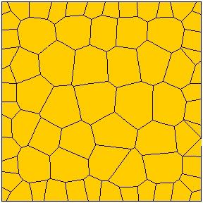
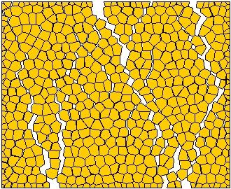
7 other authors (van Mier, Bolander, etc ) that try to capture the response mostly by disorder. It is a phenomenological approach not rooted in a real microstructure. Mesh construction A computer routine has been written to generate the particles, see Figure 1. As input data, the boundaries of the surface to mesh, the average size of the particles and a distortion factor DF, which controls the irregularity of the particles shape, must be given. In addition, the type and average size of the finite elements utilized must be specified. The discretization of the continuum into particles is based on the Voronoi diagram. The Voronoi diagram is a collection of regions that divide space according to a set of given points (nuclei). Each region has a polygonal convex shape and corresponds to one nucleus. All the points in one region are closer to the corresponding nucleus than to any other nucleus. To obtain the coordinates of the vertices of the Voronoi regions, the routine executes a call to an external freeware DOS program named (QHULL, 2001) and then processes the output data. take in Figure 1 Material heterogeneity In heterogeneous materials the disorder of the material properties at the microlevel is a key issue in the fracture process. In the present model, material disorder is given by attributing to each particle and interface random material properties. For this purpose, values for the elastic modulus E of the particles and for the strength parameters 7
8 of the interfaces (tensile strength f t, cohesion c and friction coefficient tanφ) were generated according to a Gaussian distribution. A lower threshold, equal to zero, and an upper threshold, equal to two times the average value have been imposed for each parameter. It is noted, as an example, that for a Gaussian distribution with a coefficient of variation of 50%, the probability to generate a value beyond the referred thresholds is 5%. MODEL RESPONSE. ELEMENTARY TESTS Model utilized Elementary tests were carried out resorting to 2D simulations of mm 2 specimens in order to provide insight into the behaviour of the proposed model. Since cracks are constrained to follow particle boundaries, the influence of particle size and regularity in the mesh configuration must be investigated. For this purpose, three different values for the distortion factor DF were considered (0, 0.3 and 0.6) and, for each value, three different levels for the mesh refinement MR were assumed (denoted by n, 2n and 4n, and associated with an element size one-half and one-fourth of the original size n), see Figure 2. Given the random nature of the model, for each combination DF- MR, three analyses were performed using different randomly generated meshes. take in Figure 2 In-plane symmetry conditions have been adopted, carrying out the simulations as if the specimen was part of a larger portion. Hence, specimen boundaries remain 8
9 straight during the analysis, aiming at reproducing macro homogeneous boundary conditions. In all simulations, the nonlinear system of equations following from the finite element discretization was solved with an incremental-iterative globally convergent Newton-Raphson method with arc-length control and line-search technique. The same material properties were given to all specimens, so that only the influence of the micro-structure geometry would be assessed. The elastic properties attributed to the particles (elastic modulus E and coefficient of Poisson ν) and to the interfaces (normal modulus k n and shear modulus k s ) are given in Table I, in terms of the average values and corresponding coefficients of variation CV. The inelastic properties of the interfaces are shown in Table II. Here, f t is the tensile strength, G fi is the mode I fracture energy, c is the cohesion, G fii is the mode II fracture energy and tanφ is the friction coefficient. take in Table I and Table II A unitary value was assumed for the tensile strength and the cohesion was obtained according to c = 1.5 f t. This relation was proposed by (Lourenço, 1996) for unit-mortar interfaces. For G fi, a value in agreement with the results obtained by (Van der Pluijm, 1999) was adopted and for G fii a value about five times higher the value proposed by (Lourenço, 1996) for unit-mortar interfaces (0.1 c) was used. The friction coefficient was chosen so that the ratio between the specimen compressive and tensile strengths was about ten, which is a ratio often found for masonry units, see (Schubert, 1988). Given the fact that the approach here followed is phenomenological and not physical, the values adopted for the coefficient of variation of the different 9
10 material parameters are not related with their experimental variability but were chosen so that the overall response of the model resembles the experimental response. Compressive uniaxial behaviour The specimens described in the previous Section were numerically simulated in uniaxial compression. Typical stress-strain diagrams obtained for each type of geometry are given in Figure 3. Full post-peak behaviour was difficult to obtain even with advanced solution procedures and it was decided to concentrate in the peak strength, which is the most relevant issue of the present contribution. The behaviour observed shows that increasing distortion of the particles leads to decreasing brittleness. Moreover, a relation between brittleness and mesh refinement seems to be also present. In fact, specimens with a refinement level n show a more brittle behaviour, characterized by sudden load drops, than specimens with refinement levels 2n and 4n. However, it is noted that there is not much difference in the response beyond a level of refinement of 2n. Table III illustrates the values for the compressive strength of the specimens f c, according to the mesh distortion and level of refinement. It is noted that there is increasing variability of the strength values with increasing distortion and size of the particles. The variation obtained (it is stressed that a different mesh was generated for each analysis) fairly reproduces experimental variability of results. It is further noted that the strength values show a slight decreasing trend with increasing distortion, especially for lower levels of mesh refinement. Nevertheless, the average values for 2n and 4n can be considered as mesh size and mesh distortion independent for practical 10
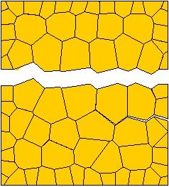
11 purposes. For this reason, relations between structural and particle sizes lower than seven to ten should be avoided. take in Figure 3 and Table III Figure 4 illustrates typical compressive crack propagation under increasing load. Three loading stages have been considered: 80% of the peak load, peak load and ultimate load. Well-known phenomena such as crack bridging and branching can be observed. Typical failure patterns obtained for the different specimens are depicted in Figure 5. It is clear that under certain combinations of particles distortion and mesh refinement, the failure pattern becomes biased by the mesh configuration. For instance, for DF = 0 and MR = 4n, the crack pattern denotes a clear diagonal tendency while, for example, for DF = 0.6 and MR = 4n, the crack pattern resembles experienced compression crack patterns with predominant vertical cracks. Thus, mesh configuration has a larger influence in the crack pattern of meshes with low distortion factors and high refinement levels. Nevertheless, the value of the failure load is not affected by the mesh preferential orientation. take in Figure 4 and Figure 5 An assessment of the contribution of the interfaces tensile and shear parameters to the compressive strength of the specimens was also performed. To achieve this purpose, compression simulations assuming different values for the tensile parameters (strength and fracture energy) were considered firstly while the model shear parameters were kept constant, see Table IV. The same approach was repeated for the shear parameters and 11
12 the results obtained are given in Table V. As expected, a decreasing trend of the compressive strength with decreasing values of the tensile and shear parameters was found, even if the simulation reduces the variation in the input significantly. However, the influence of the tensile parameters is smaller than the influence of the shear parameters. Such results seem to indicate that the compressive failure of the model in discussion is mainly governed by the parameters describing the shear behaviour. take in Table IV and Table V Tensile uniaxial behaviour Figure 6 illustrates typical stress-strain diagrams obtained in uniaxial tensile simulations. Three types of tensile response can be clearly distinguished regardless of the particle size and mesh distortion. Each type of response is associated with a different failure pattern and, for each one, the specimen mode I fracture energy can range from a value similar to the mode I fracture energy given to the interface elements up to a very large value due to a residual plateau. Such residual plateau develops when diagonal cracks appear, originating friction between the particles due to the imposed boundary (symmetry) conditions. This is clearly a problem of the boundary conditions and not of the model approach. take in Figure 6 The values obtained for the specimens tensile strength, according to the level of mesh refinement and the distortion factor, are given in Table VI. It is noted that the 12
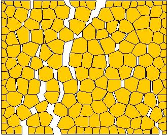
13 values found for the tensile strength found are in the range of ±10% of the unitary value used as input for the tensile strength at meso-level. This is not only due the statistical simulation of disorder but also to the tortuous crack propagation, confirming the discussion addressed previously between macro and meso-properties. Slightly decreasing values for the tensile strength were found for increasing values of the distortion factor. However, the average values can be considered as mesh size and mesh distortion independent for practical purposes. Moreover, it is noted that increasing mesh refinement is accompanied by decreasing variability of the strength values and rather low values for the coefficient of variation are obtained for MR = 4n. Please note that the specimen size is always kept constant and only the size of the particles is reduced. take in Table VI Figure 7 illustrates typical tensile crack propagation under increasing loading. Again, three loading stages have been considered: 80% of the peak load, peak load and ultimate load. Initially, several cracks start developing but at some point localization of deformation occur in one crack while, in the others, unloading occurs. Figure 8 depicts typical failure patterns obtained for different refinement and distortion levels. Rather irregular failure patterns were obtained despite the particle size and mesh distortion, influencing the model response as shown above in Figure 6. take in Figure 7 and Figure 8 Size effect 13
14 The effect of size is an important issue when estimating the strength or stressstrain relationship of quasibrittle materials. In the early 1980 s, it became clear that size effect of such materials is mainly related with the release of the structure stored energy into the front of the propagating fracture or cracking zone and can not be explained solely by Weibull-type statistics of random micro-defects, see (Bazant and Planas, 1998) and (Kim and Yi, 2002) for a comprehensive reviews. In fact, the larger the structure, the greater is the volume from which the energy is released and since the fracture front dissipates the same amount of energy, regardless of the structure size, in a larger structure the failure load must be lower. Although size effect has been widely studied for tensile failure, cracking localization is also present under compressive loading and, thus, also compressed elements show size effect, e.g. (Van Mier, 1997). It is now well known that compressive strength and post-peak ductility tend to increase with decreasing size of the structural element. In the field of concrete, models where the material structure is represented have been proved to be of great interest in understanding size effect phenomenon. In such simulations, the model parameters are set to a level below the level of observation (macro-level) and do not depend on size. Insight on this type of approach can be found in (Vonk, 1993) and (Van Vliet, 2000). The ability of the proposed micro-model to describe the influence of the specimen size has been assessed by simulations on square specimens with , and mm 2. In addition, the influence of the shape of the specimen has been investigated by considering rectangular specimens with different height over width ratios (10 30 mm 2 and mm 2 ). A distortion factor DF = 0.3 and a mesh refinement MR = 2n have been considered. In the case of square specimens, the mesh configuration and the material properties were kept constant, being the specimens only scaled. In this 14
15 way, the results can be directly compared without the effect of randomness. In the case of the rectangular specimens, the same procedure could not be applied and three simulations were carried out for each shape considering the same average parameters adopted in the square specimens simulations. From the stress-strain diagrams illustrated in Figure 9a it can be observed that the size of the specimens has a remarkable influence in the response of the model. In fact, size dependency is one of the advantages of particle-type models when compared to softening continuum models, see e.g. (Cusatis et al., 2003). Moreover, it is noted that the shape of the elements has a minor influence on the strength but an increase of brittleness was found for higher height over width ratios, see Figure 9b. take in Figure 9 The size dependent responses exhibited by the model can be explained based on the following energy balance dv = G f S V E ds (1) where the first term is the volume integral of the maximum specific energy E (by volume) stored in the specimen and the second term is the integral of the total energy released in the fracture process. G f is, then, the fracture energy given to the interfaces in the model. Moreover, specimens with equal strengths must store the same specific energy E. Considering equal shape 2D elements only differing by a scale factor, it is reasonable to assume that the crack patterns would resemble and that the number of cracks would be similar. In this way, the dissipation zone is increasing proportionally to the height of the specimen and, by energy balance, also is the stored energy. However, 15
16 for the specimens to have the same strength, the maximum stored energy should be increasing proportionally to the area of the element. If the fracture energy given to the interface elements is modified to account for these aspects, see Equation (2), size independent responses are obtained. G G b 1 f,1 = f,2 (2) b2 In the above, b is the width of the specimens and the subscript stands for the different size specimens under consideration. Figure 12 illustrates the stress-strain diagrams obtained regarding the mm 2 specimen as reference and by adapting the fracture energy (mode I and mode II) of the mm 2 and mm 2 specimens according to Equation 2. It can be observed that the response becomes totally independent from the specimen size. When there is only an increase in the height or width of the specimen, it was shown that the strength value predicted by the particle model is almost not affected, see Figure 9b. This can be explained by the fact that the increase of the stored energy is proportional to the increase of the dissipation zone. In fact, in the case of an increase in height, the cracks length can be assumed to increase roughly as much as the specimen height while in the case of an increase in width, the number of cracks can be considered to increase proportionally take in Figure 12 MODELLING MASONRY 16
17 In the previous sections the proposed particle model has been introduced and insight on the model behaviour has been provided. In this Section, the ability of the model to reproduce the behaviour of running-bond masonry prisms under uniaxial compression is assessed by means of a comparison with experimental results and with numerical results using a non-linear continuum finite element model. Brief description of adopted experimental results (Binda et al., 1988) carried out deformation controlled tests on running bond masonry prisms with dimensions of mm 3, built up with nine courses of mm 3 solid soft mud bricks and 10 mm thick mortar joints. Three different types of mortar, denoted as M1, M2 and M3, have been considered and testing aimed at the evaluation of the compressive properties of the prisms. For each type of mortar, a total of three prisms were tested. The tests were carried out in a uniaxial testing machine MTS , with non-rotating steel plates and a maximum capacity of 2500 kn. The applied load was measured by a load cell located between the upper plate and the testing machine, while displacements up to the peak load were measured with a removable strain gauge, see Figure 10. In addition, the average vertical displacement of each prism was also recorded with the machine in-built displacement transducer, permitting to capture the complete stress-strain diagram, including the softening regime. In this study, the prisms vertical strains and elastic moduli were calculated from the transducer measured displacements. Teflon sheets were placed between the prisms and the loading plates in order to minimize restraining frictional stresses. 17
18 The characteristics of the masonry components in terms of compressive strength f c, flexural tensile strength f f, elastic modulus E and coefficient of Poisson ν are given in Table VII. The results obtained for the prisms are given in Table VIII. Prisms P1, P2 and P3 were built with mortars M1, M2 and M3 of increasing strength, respectively. The experimental failure patterns found were rather similar despite the type of mortar used, (Frigerio and Frigerio, 1985). Figure 11 depicts the typical failure pattern. take in Figure 10 take in Table VII and Table VIII take in Figure 11 Description of the continuum model The simulations were carried out resorting to a basic cell, i.e., a periodic pattern associated to a frame of reference, see Figure 13, in which units and mortar were represented by a structured continuum finite element mesh. However, to reduce computational effort only a quarter of the basic cell was modelled assuming symmetry conditions for the in-plane boundaries, see Figure 14. The dimensions of the components are equal to the ones used in the experiments. take in Figure 13 and Figure 14 Three different plane approaches can be considered taking into account the out-ofplane boundaries, namely: (a) plane-stress PS, (b) plane-strain PE and (c) an intermediate state, here named enhanced-plane-strain EPE. This last approach consists 18
19 in modelling a thin out-of-plane masonry layer with 3D elements, imposing equal displacements in the two faces of the layer. Full 3D analyses with refined meshes and softening behaviour are unwieldy, and were not considered. Moreover, recent research indicated that enhanced-plane-stress analysis provides very similar results, see (Berto et al., 2005). EPE response is always between the extreme responses obtained with PS and PE. For this reason, EPE is accepted as the reference solution for the continuum simulations and only its results are considered in this paper. A complete description of the continuum simulations can be found in (Pina-Henriques and Lourenço, 2003). Modelling of the cell in EPE was carried out using approximately noded brick elements with 6650 nodes, totalling degrees of freedom (note that the tying adopted for the out-of-plane degrees of freedom mean that, basically, a 2D model is used) Gauss integration was used. The material behaviour was described using a composite model including a traditional smeared crack model in tension, specified as a combination of tension cut-off (two orthogonal cracks), tension softening and shear retention, see (Rots, 1988), and a Drucker-Prager plasticity model in compression, see also (DIANA, 2003). The inelastic behaviour exhibits a parabolic hardening/softening diagram in compression and an exponential-type softening diagram in tension. The material behaves elastically up to one-third of the compressive strength and up to the tensile strength. Description of the particle model The particle model simulations were carried out employing the same basic cell used for the continuum model, see Figure 13. The particle model is composed by approximately 19
20 13000 linear triangular continuum elements, 6000 linear line interface elements and nodes, see Figure 15. Macro homogeneous symmetry conditions and a distortion factor equal to 0.3 have been assumed. It is emphasised that the basic cell approach is only approximate of the real geometry of the specimens and that the obtained numerical response is phenomenological, which means that a comparison in terms of experimental and numerical failure patterns is not possible. In particular, splitting cracks usually observed in prisms tested under compression, e.g. (Mann and Betzler, 1994), boundary effects of the specimen and non-symmetric failure modes are not captured by the numerical analysis. Nevertheless, most of these effects control mainly the post-peak response, which is not the key issue in the present contribution. take in Figure 15 The material parameters were defined by comparing the experimental and numerical responses of units and mortar considered separately. Each material was modelled resorting to specimens with the same average particle size, mesh distortion and dimensions of the masonry components used in the composite model (basic cell). Given the stochastic nature of the model, five simulations were performed for each masonry component assuming equal average values for the model material parameters. The parameters were obtained, whenever possible, from the described experimental tests but most of the inelastic parameters were unknown and had to be estimated. It is noted that the particles average elastic modulus E is larger than the experimental value due to the contribution of the interfaces deformability, characterized by k n and k s, to the overall deformability of the specimen. This correction is necessary despite the high dummy stiffnesses assumed. 20
21 On the contrary, the values adopted for the interfaces tensile strength f t are slightly lower than the specimens experimental tensile strength, given the contribution of the interfaces shear strength due to the irregular fracture plane. Again, the cohesion c was taken, in general, equal to 1.5 f t (Lourenço, 1996). However, quite low experimental ratios between the compressive and tensile strengths were reported for the units and mortars considered here, with values ranging between four and eight. Due to this reason, cohesion values lower than 1.5 f t had to be adopted for mortars M1 and M2. The values for the friction coefficient tanφ were adopted so that the numerical compressive strength showed a good agreement with the experimental strength. The values assumed for mode I fracture energy G fi have been based in recommendations supported in experimental evidence, see (CEB-FIP, 1993) and (Van der Pluijm, 1999). For mode II fracture energy G fii, a value equal to 0.5 c was assumed, with the exception of the very high strength mortar M3, for which a lower value equal to 0.3 c was adopted. The complete material parameters adopted are given in Table IX and, for such input, the response obtained is given in Table X. In addition, typical numerical stressstrain diagrams for both units and mortar specimens are illustrated in Figure 16. take in Table IX, Table X and Figure 16 Numerical results and comparison with experimental data 21
22 In order to reproduce correctly the elastic stiffness of the masonry prisms, the experimental elastic modulus of the mortar E must be adjusted by inverse fitting. In fact, the mortar experimental stiffness leads to a clear overstiff response of the numerical specimens. This can be explained by the fact that the mechanical properties of mortar inside the composite are different from mortar specimens cast separately. This is due to mortar laying and curing and represents a severe drawback of detailed micromodels. Table XI gives the adjusted mortar stiffness values E * used in the simulations. take in Table XI The numerical results obtained for the masonry prisms considering the mortar experimental Num_E and adjusted Num_E * stiffnesses are given in Table XII, where f c is the compressive strength and ε p is the peak strain. In addition, the prisms experimental results are shown for a better comparison. It is noted, however, that the reference solution for the numerical simulations is the solution provided by Num_E *. Figure 17 depicts the experimental and numerical stress-strain diagrams. take in Table XII and Figure 17 From the given results, it is clear that the experimental collapse load is overestimated by the particle and continuum models, and that the predicted strength is affected by the mortar stiffness, especially in the case of the particle model. However, a much better agreement with the experimental strength and peak strain has been achieved with the particle model, when compared to the continuum model. In fact, the numerical over experimental strength ratios ranged between 165 to 170% in the case of the 22
23 continuum model while in the case of the particle model, strength ratios ranging between 120 and 140% were found. The results obtained also show that the peak strain values are well reproduced by the particle model but large overestimations are obtained with the continuum model. In fact, for this last model, experimental over numerical peak strain ratios ranging between 190 and 510% were found. Failure patterns are an important feature when assessing numerical models. The (incremental) deformed meshes near failure are depicted in Figure 18 to Figure 20 for the continuum model and in Figure 21 for the particle model. In the case of the continuum model, the contour of the minimum principal plastic strains is also given for a better interpretation of the mechanisms governing failure. It is noted that despite the fact that only a quarter of the basic cell has been modelled, the results are shown in the entire basic cell to obtain more legible figures. take in Figure 18 to Figure 21 The numerical failure patterns obtained are similar for both continuum and particle models. Even if the proposed particle model approach is phenomenological, the failure patterns resemble well typical compression experimental patterns observed in the face of masonry specimens. In the case of prism P1, failure occurs mainly due to the development of vertical cracks in the centre of the units and along the head-joints, being the mortar in the bed-joints severely damaged. Prism P2 fails due to diffuse damage developing in units and mortar in a rather uniform manner. In the case of prism P3, diffuse damage is also present but localized crushing of the units can be clearly observed at one-half and one-sixth of the units length. 23
24 CONCLUSIONS The analysis of masonry assemblages using detailed modelling strategies is a challenging task. A particle model consisting in a phenomenological discontinuum approach has been proposed to represent the microstructure of masonry components, attempting to adequately reproduce the experimental behaviour of masonry under compression. The model is discussed in detail, including proposals for selection of numerical data, sensitivity studies, fracture processes and failure mechanisms, and size effect studies. Finally, the particle model is compared with experimental results on masonry wallets under uniaxial compression and with numerical simulations using a continuum finite element model. It is possible to conclude that: (a) discontinuum models show clear advantages when compared to standard continuum models, based on plasticity and cracking, in predicting the compressive strength and peak strain of masonry prisms from the properties of the constituents; (b) compressive and tensile strength values provided by the particle model can be considered as particle size and particle distortion independent for practical purposes; (c) relations between structural and particle sizes lower than seven to ten should be avoided in simulations; (d) size dependent responses have been obtained with the proposed model; and (e) shear parameters rather than tensile parameters play a major role at the micro-level and greatly influence the overall response of compressed masonry, as also confirmed by Vonk (1993). Suggestions for further work include validation of the proposed model for the full 2D failure envelop under biaxial loading, develop more robust solution strategies to allow tracing the softening response of the masonry-composite simulations using the proposed model, extension of the proposed particle model to 3D configurations and 24
25 seek for other models developed in discontinuum frameworks in order to provide reliable estimations of masonry compressive strength. Finally, also the ability of nonstandard continuum models, such as the microplane model, Adicionar referência Bazant et al, to simulate the compression failure of masonry based on the geometry and properties of the constituents should be evaluated. ACKNOWLEDGEMENTS The financial support by the Portuguese Foundation for Science and Technology (FCT) under grant SFRH/BD/5002/2001 awarded to J. Pina-Henriques is gratefully acknowledged. REFERENCES ACI (2004), Commentary on specification for masonry structures, ACI , Manual of Concrete Practice, Detroit, USA. Bazant, Z.P. and Planas, J. (1998), Fracture and Size Effect in Concrete and other Quasibrittle Materials, CRC Press, Florida, USA. Berto, L., Saetta, A., Scotta, R. and Vitaliani, R. (2005), Failure mechanism of masonry prism loaded in axial compression: computational aspects, Materials and Structures, RILEM, Vol 38, No 276, pp Binda, L., Fontana, A. and Frigerio, G. (1988), Mechanical behaviour of brick masonries derived from unit and mortar characteristics, Proc 8 th International Brick/Block Masonry Conference, Dublin, Ireland, Vol 1, pp
26 Bolander, J.E., Hong, G.S. and Yoshitake, K. (2000), Structural concrete analysis using rigid-body-spring networks, Computer-Aided Civil and Infrastructure Engineering, Vol. 15, pp Brencich, A. and Gambarotta, L. (2005), Mechanical response of solid clay brickwork under eccentric loading. Part I: unreinforced masonry, Materials and Structures, RILEM, Vol 38, No 276, pp Carol, I., López, C.M. and Roa, O. (2001), Micromechanical analysis of quasibrittle materials using fracture-based interface elements, International Journal of. Numerical Methods in Engineering, Vol 52, pp CEB-FIP (1993), CEB-FIP Model Code 1990, Bulletin D Information No 213/214, Comite Euro-International du Beton, T Telford, London, UK. CEN (1998), Methods of Test for Masonry: Determination of Compressive Strength, EN :1998, Brussels, Belgium. CEN (2003), Eurocode 6: Design of Masonry Structures, pren :2002, Brussels, Belgium. Cundall, P.A. (1971), A computer model for simulating progressive, large scale movements in blocky rock systems, Proc Symposium International Society Rock Mechanics, Nancy, France, Vol 1 No II-8, pp Cusatis, G., Bazant, Z.P. and Cedolin, L. (2003), Confinement-shear lattice model for concrete damage in tension and compression, Journal of Engineering Mechanics, ASCE, Vol 129, No 12, pp DIANA (2003), DIANA Finite Element Code, Version 8.1, TNO Building and Construction Research, The Netherlands. 26
27 Frigerio, G. and Frigerio, P. (1985), Influence of the Components and Surrounding Environment in the Mechanical Behaviour of Brick Masonry (in Italian), Graduation thesis, Politecnico di Milano, Milan, Italy. Gens, A., Carol, I., and Alonso, E. (1988), An interface element formulation for the analysis of soil-reinforcement interaction, Computers and Geotechnics, Vol 7, pp Ingraffea, A.R. and Saouma, V.E. (1985), Numerical modelling of discrete crack propagation in reinforced and plain concrete, Fracture Mechanics of Concrete, eds. Sih, G. and Tomasso, A. Di, Martinus Nijhoff Publishers, Dordrecht, The Netherlands, pp Jing, L. (2003), A review of techniques, advances and outstanding issues in numerical modelling for rock mechanics and rock engineering, International Journal of Rock Mechanics & Mining Sciences, Vol 40, pp Kim, J.K. and Yi, S.T. (2002), Application of size effect to compressive strength of concrete members, Sadhana, Vol 27, No 4, pp Lemos, J.V. (2001), Modelling the behaviour of a stone masonry arch structure under cyclic loads, Proc 5 th International Symposium on Computer Methods in Structural Masonry, Rome, Italy, pp Lotfi, H.R. and Shing, P.B. (1994), Interface model applied to fracture of masonry structures, Journal of Structural Engineering, ASCE, Vol 120, No 1, pp Lorig, L.J. and Cundall, P.A. (1987), Modelling of reinforced concrete using the distinct element method, Proc SEM/RILEM International Conference on Fracture of Concrete and Rock, Houston, USA, pp
28 Lourenço, P.B. (1996), A User/Programmer Guide for the Micro-modelling of Masonry Structures, Report , Delft University of Technology, Delft, The Netherlands. Available from Lourenço, P.B. and Rots, J.G. (1997), A multi-surface interface model for the analysis of masonry structures, Journal of Engineering Mechanics, ASCE, Vol 123 No 7, pp Mann, W. and Betzler, M. (1994), Investigations on the effect of different forms of test samples to test the compressive strength of masonry, Proc 10 th International. Brick and Block Masonry Conference, Calgary, Canada, pp Pina-Henriques, J. and Lourenço, P.B. (2003), Testing and modelling of masonry creep and damage in uniaxial compression, Proc International Conference on Structural Studies, Repairs and Maintenance of Heritage Architecture, Halkidiki, Greece, pp QHULL (2001), QHULL, Version 3.1, Barber, C.B. and Huhdanpaa, H., University of Minnesota, Minneapolis, USA. Roman, H.R. and Gomes, I.R. (2004), Numerical modelling of blockwork prisms tested in compression using the finite element method with interface behaviour, Proc. 13 th International Brick/Block Masonry Conference, Amsterdam, The Netherlands, Vol 2, pp Rots, J.G. (1988), Computational Modelling of Concrete Fracture, PhD thesis, Delft University of Technology, Delft, The Netherlands. Rots, J.G. and Schellekens, J.C.J. (1990), Interface elements in concrete mechanics, Computer Aided Analysis and Design of Concrete Structures, eds. Bicanic, N. and Mang, H., Pineridge Press, Swansea, UK, pp
29 Schellekens, J.C. (1992), Computational Strategies for Composite Structures, PhD thesis, Delft University of Technology, Delft, The Netherlands. Schlangen, E. (1993), Experimental and numerical analysis of fracture processes in concrete, Heron, Vol 38 No 2, pp Schubert, P. (1988), The influence of mortar on the strength of masonry, Proc. 8 th International Brick/Block Masonry Conference, London, UK, pp Shi, G.H. (1988), Discontinuous Deformation Analysis - a New Numerical Model for the Statics and Dynamics of Block Systems, PhD thesis, University of California, Berkeley, USA. Van der Pluijm, R. (1999), Out-of-plane Bending of Masonry: Behaviour and Strength, PhD thesis, Delft University of Technology, Delft, the Netherlands. Van Mier, J.G.M., Schlangen, E. and Vervuurt, A. (1995), Lattice type fracture models for concrete, in Mühlhaus, H. (Ed.), Continuum Models for Materials with Microstructure, John Wiley & Sons, New York, USA, pp Van Mier, J.G.M. (1997), Fracture Processes of Concrete, CRC Press, Boca Raton, USA. Van Vliet, M. (2000), Size Effect in Tensile Fracture of Concrete and Rock, PhD thesis, Delft University of Technology, Delft, The Netherlands. Vonk, R.A. (1993), A micromechanical investigation of softening of concrete loaded in compression, Heron, Vol 38 No 3, pp
 particles mesh and (b) interfaces")
30 FIGURES (a) (b) Figure 1 Finite element mesh: (a) particles mesh and (b) interfaces mesh.


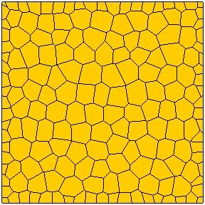

31 MR = n MR = 2n MR = 4n DF = 0 DF = 0.3 DF = 0.6 Figure 2 Geometry of the mm 2 specimens used in the simulations. Three distortion factors DF and mesh refinement levels MR were considered.
32 Stress [N/mm 2 ] n 4n n Stress [N/mm 2 ] n 2n n Strain [10-3 ] (a) Strain [10-3 ] (b) n Stress [N/mm 2 ] n 4n Strain [10-3 ] Figure 3 Typical compressive stress-strain diagrams obtained for three different levels of mesh refinement (n, 2n and 4n) and three different distortion factors: (c) (a) DF = 0, (b) DF = 0.3 and (c) DF = 0.6.


")
33 (a) (b) (c) Figure 4 Typical progressive compressive failure of a specimen. Deformed meshes at: (a) 80% of the peak load, (b) peak load and (c) ultimate load.


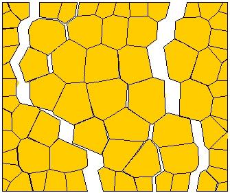
34 MR = n MR = 2n MR = 4n DF = 0 DF = 0.3 DF = 0.6 Figure 5 Typical deformed meshes obtained from the compression simulations, using three distortion factors DF and mesh refinement levels MR.
![1.2 Stress [N/mm 2 ] 0.8 0.4 b a a b 0.0 0.0 2.0 4.0 6.0 8.](/docs-images/88/114686313/images/35-0.jpg "0 10.0 Strain [10-3 ] c c Figure 6 - Tensile stress-strain")


35 1.2 Stress [N/mm 2 ] b a a b Strain [10-3 ] c c Figure 6 - Tensile stress-strain diagrams and failure patterns obtained for specimens with MR = 2n and DF = 0.3. (a) (b) (c) Figure 7 Typical progressive tensile failure of a specimen. Deformed meshes at: (a) 80% of the peak load, (b) peak load and (c) ultimate load.


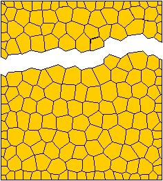
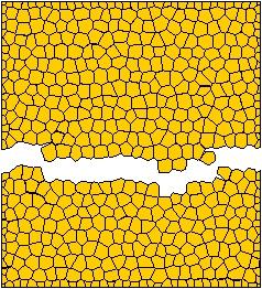
36 MR = n MR = 2n MR = 4n DF = 0 DF = 0.3 DF = 0.6 Figure 8 Typical deformed meshes obtained from the tension simulations. Three distortion factors DF and mesh refinement levels MR were considered.
37 Stress [N/mm 2 ] mm mm mm Strain [10-3 ] Stress [N/mm 2 ] f c = 15.2 f c = 15.4 f c = Strain [10-3 ] (a) (b) Figure 9 Stress-strain diagrams obtained for specimens with: (a) different size and (b) different shape. In this last figure, typical diagrams and the average compressive strength values f c obtained from three different simulations are given for each shape (10 30, and mm 2 ).
38 Figure 10 - Tested masonry wallets and location of strain gauge measurements, Binda et al. (1988). The dimensions are in mm. Figure 11 - Typical experimental failure patterns, Frigerio and Frigerio (1985). The shaded areas indicate spalling of material.
![15.0 Stress [N/mm 2 ] 12.0 9.0 6.0 3.0 10 10 mm 2 (G f = G f * /10) 50 50 mm 2 (G f = G f * /2) 100 100 mm 2 (G f = G f * ) 0.0 0.0-2.0-4.0-6.0-8.](/docs-images/88/114686313/images/39-0.jpg "0 Strain [10-3 ] Figure 12 - Stress-strain diagrams obtained by adapting the fracture energy G f as a function of the initial value G f * in order to obtain a size independent response.")
39 15.0 Stress [N/mm 2 ] mm 2 (G f = G f * /10) mm 2 (G f = G f * /2) mm 2 (G f = G f * ) Strain [10-3 ] Figure 12 - Stress-strain diagrams obtained by adapting the fracture energy G f as a function of the initial value G f * in order to obtain a size independent response (a) (b) Figure 13 Definition of basic cell: (a) running bond masonry and (b) geometry. Mortar Unit Figure 14 Continuum model (a quarter of the basic cell, assuming symmetry conditions).
![Mortar Unit Figure 15 Particle model (a quarter of the basic cell, assuming symmetry conditions). Stress [N/mm 2 ] 30.0 24.0 18.0 12.0 6.0 Unit Stress [N/mm 2 ] 4.0 3.0 2.0 1.0 M1 0.0 10.0 5.0 0.0-5.](/docs-images/88/114686313/images/40-0.jpg "0-10.0 Strain [10-3 ] (a) 0.0 10.0 5.0 0.0-5.0-10.0 Strain [10-3 ] (b) Stress [N/mm 2 ] 15.0 12.0 9.0 6.0 3.0 M2 Stress [N/mm 2 ] 120.0 90.0 60.0 30.0 M3 0.0 10.0 5.0 0.0-5.0-10.0 Strain [10-3 ] (c) 0.")
40 Mortar Unit Figure 15 Particle model (a quarter of the basic cell, assuming symmetry conditions). Stress [N/mm 2 ] Unit Stress [N/mm 2 ] M Strain [10-3 ] (a) Strain [10-3 ] (b) Stress [N/mm 2 ] M2 Stress [N/mm 2 ] M Strain [10-3 ] (c) Strain [10-3 ] (d) Figure 16 Typical numerical stress-strain diagrams obtained for the masonry components: (a) unit, (b) mortar M1, (c) mortar M2 and (d) mortar M3.
41 PM CM CM Stress [N/mm 2 ] Exp Stress [N/mm 2 ] PM Exp Strain [10-3 ] (a) Strain [10-3 ] (b) 35.0 Stress [N/mm 2 ] PM Exp CM Strain [10-3 ] (c) Figure 17 Numerical and experimental stress-strain diagrams, using adjusted mortar stiffness values, for prism: (a) P1, (b) P2 and (c) P3. In the diagrams, PM stands for particle model, CM for continuum model, and Exp for experimental data.

 minimum principal plastic")
 (b) Figure 19 Results obtained at")
 (b) Figure 20 Results obtained at")


42 (a) (b) Figure 18 Results obtained at failure for prism P1 using the continuum model: (a) deformed (incremental) mesh and (b) minimum principal plastic strains. (a) (b) Figure 19 Results obtained at failure for prism P2 using the continuum model: (a) deformed (incremental) mesh and (b) minimum principal plastic strains. (a) (b) Figure 20 Results obtained at failure for prism P3 using the continuum model: (a) deformed (incremental) mesh and (b) minimum principal plastic strains.


 P1,")
43 (a) (b) (c) Figure 21 Deformed (incremental) meshes near failure using the particle model for prisms: (a) P1, (b) P2 and (c) P3.
MASONRY MICRO-MODELLING ADOPTING A DISCONTINUOUS FRAMEWORK
 MASONRY MICRO-MODELLING ADOPTING A DISCONTINUOUS FRAMEWORK J. Pina-Henriques and Paulo B. Lourenço School of Engineering, University of Minho, Guimarães, Portugal Abstract Several continuous and discontinuous
6. NON-LINEAR PSEUDO-STATIC ANALYSIS OF ADOBE WALLS
 6. NON-LINEAR PSEUDO-STATIC ANALYSIS OF ADOBE WALLS Blondet et al. [25] carried out a cyclic test on an adobe wall to reproduce its seismic response and damage pattern under in-plane loads. The displacement
ALGORITHM FOR NON-PROPORTIONAL LOADING IN SEQUENTIALLY LINEAR ANALYSIS
 9th International Conference on Fracture Mechanics of Concrete and Concrete Structures FraMCoS-9 Chenjie Yu, P.C.J. Hoogenboom and J.G. Rots DOI 10.21012/FC9.288 ALGORITHM FOR NON-PROPORTIONAL LOADING
Limit analysis of brick masonry shear walls with openings under later loads by rigid block modeling
 Limit analysis of brick masonry shear walls with openings under later loads by rigid block modeling F. Portioli, L. Cascini, R. Landolfo University of Naples Federico II, Italy P. Foraboschi IUAV University,
Structural behaviour of traditional mortise-and-tenon timber joints
 Structural behaviour of traditional mortise-and-tenon timber joints Artur O. Feio 1, Paulo B. Lourenço 2 and José S. Machado 3 1 CCR Construtora S.A., Portugal University Lusíada, Portugal 2 University
Finite element analysis of diagonal tension failure in RC beams
 Finite element analysis of diagonal tension failure in RC beams T. Hasegawa Institute of Technology, Shimizu Corporation, Tokyo, Japan ABSTRACT: Finite element analysis of diagonal tension failure in a
Numerical Modelling of Blockwork Prisms Tested in Compression Using Finite Element Method with Interface Behaviour
 13 th International Brick and Block Masonry Conference Amsterdam, July 4-7, 2004 Numerical Modelling of Blockwork Prisms Tested in Compression Using Finite Element Method with Interface Behaviour H. R.
EDEM DISCRETIZATION (Phase II) Normal Direction Structure Idealization Tangential Direction Pore spring Contact spring SPRING TYPES Inner edge Inner d
 Normal Direction Structure Idealization Tangential Direction Pore spring Contact spring SPRING TYPES Inner edge Inner d") Institute of Industrial Science, University of Tokyo Bulletin of ERS, No. 48 (5) A TWO-PHASE SIMPLIFIED COLLAPSE ANALYSIS OF RC BUILDINGS PHASE : SPRING NETWORK PHASE Shanthanu RAJASEKHARAN, Muneyoshi
Institute of Industrial Science, University of Tokyo Bulletin of ERS, No. 48 (5) A TWO-PHASE SIMPLIFIED COLLAPSE ANALYSIS OF RC BUILDINGS PHASE : SPRING NETWORK PHASE Shanthanu RAJASEKHARAN, Muneyoshi
Numerical Characterization of Concrete Heterogeneity
 Vol. Materials 5, No. Research, 3, 2002Vol. 5, No. 3, Statistical 309-314, 2002. Characterization of the Concrete Numerical Modeling of Size Effect In Heterogeneity 2002 309 Numerical Characterization
Fluid driven cohesive crack propagation in quasi-brittle materials
 Fluid driven cohesive crack propagation in quasi-brittle materials F. Barpi 1, S. Valente 2 Department of Structural and Geotechnical Engineering, Politecnico di Torino, Corso Duca degli Abruzzi 24, 10129
3D Finite Element analysis of stud anchors with large head and embedment depth
 3D Finite Element analysis of stud anchors with large head and embedment depth G. Periškić, J. Ožbolt & R. Eligehausen Institute for Construction Materials, University of Stuttgart, Stuttgart, Germany
A Performance Modeling Strategy based on Multifiber Beams to Estimate Crack Openings ESTIMATE in Concrete Structures CRACK
 A Performance Modeling Strategy based on Multifiber Beams to Estimate Crack Openings ESTIMATE in Concrete Structures CRACK A. Medjahed, M. Matallah, S. Ghezali, M. Djafour RiSAM, RisK Assessment and Management,
Cracked concrete structures under cyclic load
 Cracked concrete structures under cyclic load Fabrizio Barpi & Silvio Valente Department of Structural and Geotechnical Engineering, Politecnico di Torino, Torino, Italy ABSTRACT: The safety of cracked
Discrete Element Modelling of a Reinforced Concrete Structure
 Discrete Element Modelling of a Reinforced Concrete Structure S. Hentz, L. Daudeville, F.-V. Donzé Laboratoire Sols, Solides, Structures, Domaine Universitaire, BP 38041 Grenoble Cedex 9 France sebastian.hentz@inpg.fr
5 ADVANCED FRACTURE MODELS
 Essentially, all models are wrong, but some are useful George E.P. Box, (Box and Draper, 1987) 5 ADVANCED FRACTURE MODELS In the previous chapter it was shown that the MOR parameter cannot be relied upon
MESOSCOPIC MODELLING OF MASONRY USING GFEM: A COMPARISON OF STRONG AND WEAK DISCONTINUITY MODELS B. Vandoren 1,2, K. De Proft 2
 Blucher Mechanical Engineering Proceedings May 2014, vol. 1, num. 1 www.proceedings.blucher.com.br/evento/10wccm MESOSCOPIC MODELLING OF MASONRY USING GFEM: A COMPARISON OF STRONG AND WEAK DISCONTINUITY
Analysis of Blocky Rock Slopes with Finite Element Shear Strength Reduction Analysis
 Analysis of Blocky Rock Slopes with Finite Element Shear Strength Reduction Analysis R.E. Hammah, T. Yacoub, B. Corkum & F. Wibowo Rocscience Inc., Toronto, Canada J.H. Curran Department of Civil Engineering
Dynamic Analysis of a Reinforced Concrete Structure Using Plasticity and Interface Damage Models
 Dynamic Analysis of a Reinforced Concrete Structure Using Plasticity and Interface Damage Models I. Rhee, K.J. Willam, B.P. Shing, University of Colorado at Boulder ABSTRACT: This paper examines the global
VORONOI APPLIED ELEMENT METHOD FOR STRUCTURAL ANALYSIS: THEORY AND APPLICATION FOR LINEAR AND NON-LINEAR MATERIALS
 The 4 th World Conference on Earthquake Engineering October -7, 008, Beijing, China VORONOI APPLIED ELEMENT METHOD FOR STRUCTURAL ANALYSIS: THEORY AND APPLICATION FOR LINEAR AND NON-LINEAR MATERIALS K.
EVALUATION OF NONLOCAL APPROACHES FOR MODELLING FRACTURE IN NOTCHED CONCRETE SPECIMENS
 VIII International Conference on Fracture Mechanics of Concrete and Concrete Structures FraMCoS-8 J.G.M. Van Mier, G. Ruiz, C. Andrade, R.C. Yu and X.X. Zhang (Eds) EVALUATION OF NONLOCAL APPROACHES FOR
Mesoscopic Simulation of Failure of Mortar and Concrete by 3D RBSM
 Journal of Advanced Concrete Technology Vol., No., 85-4, October 5 / Copyright 5 Japan Concrete Institute 85 Scientific paper Mesoscopic Simulation of Failure of Mortar and Concrete by D RBSM Kohei Nagai,
NUMERICAL MODELLING AND DETERMINATION OF FRACTURE MECHANICS PARAMETERS FOR CONCRETE AND ROCK: PROBABILISTIC ASPECTS
 NUMERICAL MODELLING AND DETERMINATION OF FRACTURE MECHANICS PARAMETERS FOR CONCRETE AND ROCK: PROBABILISTIC ASPECTS J. Carmeliet Catholic University of Leuven, Department of Civil Engineering, Belgium
Heterogeneous structures studied by interphase elasto-damaging model.
 Heterogeneous structures studied by interphase elasto-damaging model. Giuseppe Fileccia Scimemi 1, Giuseppe Giambanco 1, Antonino Spada 1 1 Department of Civil, Environmental and Aerospace Engineering,
Characterization of the Cyclic Behavior of Dry Masonry Joints
 Characterization of the Cyclic Behavior of Dry Masonry Joints Paulo B. Lourenço 1 and Luís F. Ramos 2 1 Abstract Dry masonry mechanics received little attention from research community, when compared with
REGRESSION MODELING FOR STRENGTH AND TOUGHNESS EVALUATION OF HYBRID FIBRE REINFORCED CONCRETE
 REGRESSION MODELING FOR STRENGTH AND TOUGHNESS EVALUATION OF HYBRID FIBRE REINFORCED CONCRETE S. Eswari 1, P. N. Raghunath and S. Kothandaraman 1 1 Department of Civil Engineering, Pondicherry Engineering
A FINITE ELEMENT MODEL FOR SIZE EFFECT AND HETEROGENEITY IN CONCRETE STRUCTURES
 A FINITE ELEMENT MODEL FOR SIZE EFFECT AND HETEROGENEITY IN CONCRETE STRUCTURES Roque Luiz Pitangueira 1 and Raul Rosas e Silva 2 1 Department of Structural Engineering -Federal University of Minas Gerais
strain appears only after the stress has reached a certain critical level, usually specied by a Rankine-type criterion in terms of the maximum princip
 Nonlocal damage models: Practical aspects and open issues Milan Jirasek LSC-DGC, Swiss Federal Institute of Technology at Lausanne (EPFL), Switzerland Milan.Jirasek@ep.ch Abstract: The purpose of this
MESOSCALE MODELING OF CONCRETE: MICROPLANE-BASED APPROACH
 9th International Conference on Fracture Mechanics of Concrete and Concrete Structures FraMCoS-9 V. Saouma, J. Bolander and E. Landis (Eds) DOI 10.21012/FC9.296 MESOSCALE MODELING OF CONCRETE: MICROPLANE-BASED
Role of Force Resultant Interaction on Ultra-High Performance Concrete
 First International Interactive Symposium on UHPC 216 Role of Force Resultant Interaction on Ultra-High Performance Concrete Author(s) & Affiliation: Titchenda Chan (1), Kevin R. Mackie (1), and Jun Xia
CHAPTER 3 EXPERIMENTAL STUDY
 Experimental Study 42 CHAPTER 3 EXPERIMENTAL STUDY 3.1. INTRODUCTION The experimental study that has been carried out in this thesis has two main objectives: 1. Characterise the concrete behaviour in mode
THE BEHAVIOUR OF REINFORCED CONCRETE AS DEPICTED IN FINITE ELEMENT ANALYSIS.
 THE BEHAVIOUR OF REINFORCED CONCRETE AS DEPICTED IN FINITE ELEMENT ANALYSIS. THE CASE OF A TERRACE UNIT. John N Karadelis 1. INTRODUCTION. Aim to replicate the behaviour of reinforced concrete in a multi-scale
NUMERICAL SIMULATION OF THE INELASTIC SEISMIC RESPONSE OF RC STRUCTURES WITH ENERGY DISSIPATORS
 NUMERICAL SIMULATION OF THE INELASTIC SEISMIC RESPONSE OF RC STRUCTURES WITH ENERGY DISSIPATORS ABSTRACT : P Mata1, AH Barbat1, S Oller1, R Boroschek2 1 Technical University of Catalonia, Civil Engineering
EFFECT OF SHEAR REINFORCEMENT ON FAILURE MODE OF RC BRIDGE PIERS SUBJECTED TO STRONG EARTHQUAKE MOTIONS
 EFFECT OF SHEAR REINFORCEMENT ON FAILURE MODE OF RC BRIDGE PIERS SUBJECTED TO STRONG EARTHQUAKE MOTIONS Atsuhiko MACHIDA And Khairy H ABDELKAREEM SUMMARY Nonlinear D FEM was utilized to carry out inelastic
Modeling of Interfacial Debonding Induced by IC Crack for Concrete Beam-bonded with CFRP
 Proceedings of the World Congress on Engineering 21 Vol II WCE 21, June 2 - July 1, 21, London, U.K. Modeling of Interfacial Debonding Induced by IC Crack for Concrete Beam-bonded with CFRP Lihua Huang,
MESO-MECHANICAL MODELING OF ULTRA-LIGHTWEIGHT CONCRETES
 International RILEM Conference on Material Science MATSCI, Aachen 2010 Vol. II, HetMat 83 MESO-MECHANICAL MODELING OF ULTRA-LIGHTWEIGHT CONCRETES T. Vallée 1, M. Oppel 2, T. Tannert 3, 1 College of Engineering
Análisis Computacional del Comportamiento de Falla de Hormigón Reforzado con Fibras Metálicas
 San Miguel de Tucuman, Argentina September 14 th, 2011 Seminary on Análisis Computacional del Comportamiento de Falla de Hormigón Reforzado con Fibras Metálicas Antonio Caggiano 1, Guillermo Etse 2, Enzo
Numerical Modeling of Interface Between Soil and Pile to Account for Loss of Contact during Seismic Excitation
 Numerical Modeling of Interface Between Soil and Pile to Account for Loss of Contact during Seismic Excitation P. Sushma Ph D Scholar, Earthquake Engineering Research Center, IIIT Hyderabad, Gachbowli,
Module 5: Failure Criteria of Rock and Rock masses. Contents Hydrostatic compression Deviatoric compression
 FAILURE CRITERIA OF ROCK AND ROCK MASSES Contents 5.1 Failure in rocks 5.1.1 Hydrostatic compression 5.1.2 Deviatoric compression 5.1.3 Effect of confining pressure 5.2 Failure modes in rocks 5.3 Complete
FINITE ELEMENT ANALYSIS OF TAPERED COMPOSITE PLATE GIRDER WITH A NON-LINEAR VARYING WEB DEPTH
 Journal of Engineering Science and Technology Vol. 12, No. 11 (2017) 2839-2854 School of Engineering, Taylor s University FINITE ELEMENT ANALYSIS OF TAPERED COMPOSITE PLATE GIRDER WITH A NON-LINEAR VARYING
DESIGN RECOMMENDATIONS FOR REINFORCED MASONRY ARCHES
 rch Bridges RCH 04 P. Roca and E. Oñate (Eds) CIMNE, Barcelona, 004 DESIGN RECOMMENDTIONS FOR REINFORCED MSONRY RCHES Paulo B. ourenço *, Késio Palácio * and Joaquim O. Barros * * Universidade do Minho
Table of Contents. Foreword... xiii Introduction... xv
 Foreword.... xiii Introduction.... xv Chapter 1. Controllability of Geotechnical Tests and their Relationship to the Instability of Soils... 1 Roberto NOVA 1.1. Introduction... 1 1.2. Load control... 2
FRACTURE IN HIGH PERFORMANCE FIBRE REINFORCED CONCRETE PAVEMENT MATERIALS
 FRACTURE IN HIGH PERFORMANCE FIBRE REINFORCED CONCRETE PAVEMENT MATERIALS ERIK DENNEMAN A thesis submitted in partial fulfilment of the requirements for the degree of PHILOSOPHIAE DOCTOR (ENGINEERING)
A Constitutive Framework for the Numerical Analysis of Organic Soils and Directionally Dependent Materials
 Dublin, October 2010 A Constitutive Framework for the Numerical Analysis of Organic Soils and Directionally Dependent Materials FracMan Technology Group Dr Mark Cottrell Presentation Outline Some Physical
Nonlinear FE Analysis of Reinforced Concrete Structures Using a Tresca-Type Yield Surface
 Transaction A: Civil Engineering Vol. 16, No. 6, pp. 512{519 c Sharif University of Technology, December 2009 Research Note Nonlinear FE Analysis of Reinforced Concrete Structures Using a Tresca-Type Yield
Abstract. 1 Introduction
 Contact analysis for the modelling of anchors in concrete structures H. Walter*, L. Baillet** & M. Brunet* *Laboratoire de Mecanique des Solides **Laboratoire de Mecanique des Contacts-CNRS UMR 5514 Institut
POST-PEAK BEHAVIOR OF FRP-JACKETED REINFORCED CONCRETE COLUMNS
 POST-PEAK BEHAVIOR OF FRP-JACKETED REINFORCED CONCRETE COLUMNS - Technical Paper - Tidarut JIRAWATTANASOMKUL *1, Dawei ZHANG *2 and Tamon UEDA *3 ABSTRACT The objective of this study is to propose a new
Numerical modeling of standard rock mechanics laboratory tests using a finite/discrete element approach
 Numerical modeling of standard rock mechanics laboratory tests using a finite/discrete element approach S. Stefanizzi GEODATA SpA, Turin, Italy G. Barla Department of Structural and Geotechnical Engineering,
Anthony R. Ingraffea Symposium September 27, State- Based Peridynamic Lattice Modeling of Reinforced Concrete Structures ! 1
 Anthony R. Ingraffea Symposium September 27, 2014 State- Based Peridynamic Lattice Modeling of Reinforced Concrete Structures Walter Gerstle Department of Civil Engineering University of New Mexico, U.S.A.
TIME-DEPENDENT BEHAVIOR OF PILE UNDER LATERAL LOAD USING THE BOUNDING SURFACE MODEL
 TIME-DEPENDENT BEHAVIOR OF PILE UNDER LATERAL LOAD USING THE BOUNDING SURFACE MODEL Qassun S. Mohammed Shafiqu and Maarib M. Ahmed Al-Sammaraey Department of Civil Engineering, Nahrain University, Iraq
A generalisation of the Hillerborg s model for the analytical evaluation of ductility of RC beams in bending
 Magazine of Concrete Research, 21, 62, No. 8, August, 557 567 doi: 1.168/macr.21.62.8.557 A generalisation of the Hillerborg s model for the analytical evaluation of ductility of RC beams in bending E.
Cracking in Quasi-Brittle Materials Using Isotropic Damage Mechanics
 Cracking in Quasi-Brittle Materials Using Isotropic Damage Mechanics Tobias Gasch, PhD Student Co-author: Prof. Anders Ansell Comsol Conference 2016 Munich 2016-10-12 Contents Introduction Isotropic damage
An orthotropic damage model for crash simulation of composites
 High Performance Structures and Materials III 511 An orthotropic damage model for crash simulation of composites W. Wang 1, F. H. M. Swartjes 1 & M. D. Gan 1 BU Automotive Centre of Lightweight Structures
ME 2570 MECHANICS OF MATERIALS
 ME 2570 MECHANICS OF MATERIALS Chapter III. Mechanical Properties of Materials 1 Tension and Compression Test The strength of a material depends on its ability to sustain a load without undue deformation
Introduction and Background
 Introduction and Background Itasca Consulting Group, Inc. (Itasca) has been participating in the geomechanical design of the underground 118-Zone at the Capstone Minto Mine (Minto) in the Yukon, in northwestern
A Nonlinear Interface Element for 3D Mesoscale Analysis. of Brick-Masonry Structures
 A Nonlinear Interface Element for 3D Mesoscale Analysis of Brick-Masonry Structures L. Macorini 1, B.A. Izzuddin 2 Abstract This paper presents a novel interface element for the geometric and material
FLAC3D analysis on soil moving through piles
 University of Wollongong Research Online Faculty of Engineering - Papers (Archive) Faculty of Engineering and Information Sciences 211 FLAC3D analysis on soil moving through piles E H. Ghee Griffith University
Open-hole compressive strength prediction of CFRP composite laminates
 Open-hole compressive strength prediction of CFRP composite laminates O. İnal 1, A. Ataş 2,* 1 Department of Mechanical Engineering, Balikesir University, Balikesir, 10145, Turkey, inal@balikesir.edu.tr
The Finite Element Method for Solid and Structural Mechanics
 The Finite Element Method for Solid and Structural Mechanics Sixth edition O.C. Zienkiewicz, CBE, FRS UNESCO Professor of Numerical Methods in Engineering International Centre for Numerical Methods in
Comparison of Structural Models for Seismic Analysis of Multi-Storey Frame Buildings
 Comparison of Structural Models for Seismic Analysis of Multi-Storey Frame Buildings Dj. Ladjinovic, A. Raseta, A. Radujkovic & R. Folic University of Novi Sad, Faculty of Technical Sciences, Novi Sad,
SIZE EFFECT ANALYSIS OF COMPRESSIVE STRENGTH FOR RECYCLED CONCRETE USING THE BFEM ON MICROMECHANICS
 Proceedings of the 6th International Conference on Mechanics and Materials in Design, Editors: J.F. Silva Gomes & S.A. Meguid, P.Delgada/Azores, 6-3 July 5 PAPER REF: 54 SIZE EFFECT ANALYSIS OF COMPRESSIVE
PREDICTION OF THE CYCLIC BEHAVIOR OF MOMENT RESISTANT BEAM-TO-COLUMN JOINTS OF COMPOSITE STRUCTURAL ELEMENTS
 SDSS Rio 21 STABILITY AND DUCTILITY OF STEEL STRUCTURES E. Batista, P. Vellasco, L. de Lima (Eds.) Rio de Janeiro, Brazil, September 8-1, 21 PREDICTION OF THE CYCLIC BEHAVIOR OF MOMENT RESISTANT BEAM-TO-COLUMN
MODELING OF THE WEDGE SPLITTING TEST USING AN EXTENDED CRACKED HINGE MODEL
 Engineering MECHANICS, Vol. 21, 2014, No. 1, p. 67 72 67 MODELING OF THE WEDGE SPLITTING TEST USING AN EXTENDED CRACKED HINGE MODEL Tomáš Pail, Petr Frantík* The present paper describes a semi-analytical
Mesoscopic Simulation of Failure of Mortar and Concrete by 2D RBSM
 Journal of Advanced Concrete Technology Vol., No., 59-7, October / Copyright Japan Concrete Institute 59 Mesoscopic Simulation of Failure of Mortar and Concrete by D RBSM Kohei Nagai, Yasuhiko Sato and
EQUIVALENT FRACTURE ENERGY CONCEPT FOR DYNAMIC RESPONSE ANALYSIS OF PROTOTYPE RC GIRDERS
 EQUIVALENT FRACTURE ENERGY CONCEPT FOR DYNAMIC RESPONSE ANALYSIS OF PROTOTYPE RC GIRDERS Abdul Qadir Bhatti 1, Norimitsu Kishi 2 and Khaliq U Rehman Shad 3 1 Assistant Professor, Dept. of Structural Engineering,
MECE 3321 MECHANICS OF SOLIDS CHAPTER 3
 MECE 3321 MECHANICS OF SOLIDS CHAPTER 3 Samantha Ramirez TENSION AND COMPRESSION TESTS Tension and compression tests are used primarily to determine the relationship between σ avg and ε avg in any material.
NUMERICAL MODELLING AND DETERMINATION OF FRACTURE MECHANICS PARAMETERS FOR CONCRETE ROCK: INTRODUCTION
 NUMERICAL MODELLING AND DETERMINATION OF FRACTURE MECHANICS PARAMETERS FOR CONCRETE ROCK: INTRODUCTION J.G.M. van Mier Delft University of Technology, Faculty of Civil Engineering, Stevin Laboratory, Delft,
Modelling the nonlinear shear stress-strain response of glass fibrereinforced composites. Part II: Model development and finite element simulations
 Modelling the nonlinear shear stress-strain response of glass fibrereinforced composites. Part II: Model development and finite element simulations W. Van Paepegem *, I. De Baere and J. Degrieck Ghent
TIME-DEPENDENT MESOSCOPIC MODELLING OF MASONRY USING EMBEDDED WEAK DISCONTINUITIES
 XI International Conference on Computational Plasticity. Fundamentals and Applications COMPLAS 2011 E. Oñate and D.R.J. Owen (Eds) TIME-DEPENDENT MESOSCOPIC MODELLING OF MASONRY USING EMBEDDED WEAK DISCONTINUITIES
EFFECT OF THE TEST SET-UP ON FRACTURE MECHANICAL PARAMETERS OF CONCRETE
 Fracture Mechanics of Concrete Structures Proceedings FRAMCOS-3 AEDIFICATIO Publishers, D-79104 Freiburg, Germany EFFECT OF THE TEST SET-UP ON FRACTURE MECHANICAL PARAMETERS OF CONCRETE V. Mechtcherine
Enhancing Prediction Accuracy In Sift Theory
 18 TH INTERNATIONAL CONFERENCE ON COMPOSITE MATERIALS Enhancing Prediction Accuracy In Sift Theory J. Wang 1 *, W. K. Chiu 1 Defence Science and Technology Organisation, Fishermans Bend, Australia, Department
NON-LINEAR STATIC ANALYSIS OF MASONRY STRUCTURES
 Non-linear static analysis of masonry structures XIII International Conference on Computational Plasticity. Fundamentals and Applications COMPLAS XIII E. Oñate, D.R.J. Owen, D. Peric & M. Chiumenti (Eds)
TESTS ON REINFORCED CONCRETE LOW-RISE SHEAR WALLS UNDER STATIC CYCLIC LOADING
 13 th World Conference on Earthquake Engineering Vancouver, B.C., Canada August 1-6, 2004 Paper No.257 TESTS ON REINFORCED CONCRETE LOW-RISE SHEAR WALLS UNDER STATIC CYCLIC LOADING Marc BOUCHON 1, Nebojsa
Centrifuge Shaking Table Tests and FEM Analyses of RC Pile Foundation and Underground Structure
 Centrifuge Shaking Table s and FEM Analyses of RC Pile Foundation and Underground Structure Kenji Yonezawa Obayashi Corporation, Tokyo, Japan. Takuya Anabuki Obayashi Corporation, Tokyo, Japan. Shunichi
An Energy Dissipative Constitutive Model for Multi-Surface Interfaces at Weld Defect Sites in Ultrasonic Consolidation
 An Energy Dissipative Constitutive Model for Multi-Surface Interfaces at Weld Defect Sites in Ultrasonic Consolidation Nachiket Patil, Deepankar Pal and Brent E. Stucker Industrial Engineering, University
Brittle Deformation. Earth Structure (2 nd Edition), 2004 W.W. Norton & Co, New York Slide show by Ben van der Pluijm
, 2004 W.W. Norton & Co, New York Slide show by Ben van der Pluijm") Lecture 6 Brittle Deformation Earth Structure (2 nd Edition), 2004 W.W. Norton & Co, New York Slide show by Ben van der Pluijm WW Norton, unless noted otherwise Brittle deformation EarthStructure (2 nd
Lecture 6 Brittle Deformation Earth Structure (2 nd Edition), 2004 W.W. Norton & Co, New York Slide show by Ben van der Pluijm WW Norton, unless noted otherwise Brittle deformation EarthStructure (2 nd
DYNAMIC ANALYSIS OF PILES IN SAND BASED ON SOIL-PILE INTERACTION
 October 1-17,, Beijing, China DYNAMIC ANALYSIS OF PILES IN SAND BASED ON SOIL-PILE INTERACTION Mohammad M. Ahmadi 1 and Mahdi Ehsani 1 Assistant Professor, Dept. of Civil Engineering, Geotechnical Group,
SOIL MODELS: SAFETY FACTORS AND SETTLEMENTS
 PERIODICA POLYTECHNICA SER. CIV. ENG. VOL. 48, NO. 1 2, PP. 53 63 (2004) SOIL MODELS: SAFETY FACTORS AND SETTLEMENTS Gabriella VARGA and Zoltán CZAP Geotechnical Department Budapest University of Technology
FE-Analysis of Stringer-to-floor-beam Connections in Riveted Railway Bridges
 FE-Analysis of Stringer-to-floor-beam Connections in Riveted Railway Bridges By Mohammad Al-Emrani 1 and Robert Kliger 2 Department of Structural Engineering Chalmers University of Technology, SE-412 96
Ultimate Strength Analysis of Normal and High Strength Concrete Wall. Panels with Varying Opening Configurations
 Ultimate Strength Analysis of Normal and High Strength Concrete Wall Panels with Varying Opening Configurations Hong Guan a, Carlia Cooper b and Dong-Jun Lee a a Griffith School of Engineering, Griffith
Constitutive Modeling of Reinforced Concrete Panel Behavior under Cyclic Loading
 Constitutive Modeling of Reinforced Concrete Panel Behavior under Cyclic Loading K. Orakcal & D. Ulugtekin Bogazici University, Istanbul, Turkey L. M. Massone University of Chile, Santiago, Chile SUMMARY:
Finite Element Analysis of FRP Debonding Failure at the Tip of Flexural/Shear Crack in Concrete Beam
 Marquette University e-publications@marquette Civil and Environmental Engineering Faculty Research and Publications Civil and Environmental Engineering, Department of 12-1-2013 Finite Element Analysis
Influence of bond-slip on the behaviour of reinforced concrete beam to column joints
 Tailor Made Concrete Structures Walraven & Stoelhorst (eds) 2008 Taylor & Francis Group, London, ISBN 978-0-415-47535-8 Influence of bond-slip on the behaviour of reinforced concrete beam to column joints
CHAPTER 6: ULTIMATE LIMIT STATE
 CHAPTER 6: ULTIMATE LIMIT STATE 6.1 GENERAL It shall be in accordance with JSCE Standard Specification (Design), 6.1. The collapse mechanism in statically indeterminate structures shall not be considered.
A METHOD OF LOAD INCREMENTS FOR THE DETERMINATION OF SECOND-ORDER LIMIT LOAD AND COLLAPSE SAFETY OF REINFORCED CONCRETE FRAMED STRUCTURES
 A METHOD OF LOAD INCREMENTS FOR THE DETERMINATION OF SECOND-ORDER LIMIT LOAD AND COLLAPSE SAFETY OF REINFORCED CONCRETE FRAMED STRUCTURES Konuralp Girgin (Ph.D. Thesis, Institute of Science and Technology,
Chapter 4. Test results and discussion. 4.1 Introduction to Experimental Results
 Chapter 4 Test results and discussion This chapter presents a discussion of the results obtained from eighteen beam specimens tested at the Structural Technology Laboratory of the Technical University
FEM for elastic-plastic problems
 FEM for elastic-plastic problems Jerzy Pamin e-mail: JPamin@L5.pk.edu.pl With thanks to: P. Mika, A. Winnicki, A. Wosatko TNO DIANA http://www.tnodiana.com FEAP http://www.ce.berkeley.edu/feap Lecture
NUMERICAL SIMULATIONS OF CORNERS IN RC FRAMES USING STRUT-AND-TIE METHOD AND CDP MODEL
 Numerical simulations of corners in RC frames using Strut-and-Tie Method and CDP model XIII International Conference on Computational Plasticity. Fundamentals and Applications COMPLAS XIII E. Oñate, D.R.J.
DEVELOPMENT OF AUTOMATIC CONTROL OF MULTI-STAGE TRIAXIAL TESTS AT THE UNIVERSITY OF MISKOLC
 Geosciences and Engineering, Vol. 2, No. 3 (2013), pp. 37 43. DEVELOPMENT OF AUTOMATIC CONTROL OF MULTI-STAGE TRIAXIAL TESTS AT THE UNIVERSITY OF MISKOLC BALÁZS CSUHANICS ÁKOS DEBRECZENI Institute of Mining
Pillar strength estimates for foliated and inclined pillars in schistose material
 Pillar strength estimates for foliated and inclined pillars in schistose material L.J. Lorig Itasca Consulting Group, Inc., Minneapolis, MN, USA A. Cabrera Itasca S.A., Santiago, Chile ABSTRACT: Pillar
An Atomistic-based Cohesive Zone Model for Quasi-continua
 An Atomistic-based Cohesive Zone Model for Quasi-continua By Xiaowei Zeng and Shaofan Li Department of Civil and Environmental Engineering, University of California, Berkeley, CA94720, USA Extended Abstract
Non-local damage modeling of high performance concrete exposed to high temperature
 Non-local damage modeling of high performance concrete exposed to high temperature L. Ferrara & R. Felicetti Department of Structural Engineering, Politecnico di Milano, Italy. ABSTRACT: In this work the
Experimental and theoretical characterization of Li 2 TiO 3 and Li 4 SiO 4 pebbles
 Experimental and theoretical characterization of Li 2 TiO 3 and Li 4 SiO 4 s D. Aquaro 1 N. Zaccari ABSTRACT Dipartimento di Ingegneria Meccanica Nucleare e della Produzione University of Pisa (Italy)
NUMERICAL ANALYSIS OF A PILE SUBJECTED TO LATERAL LOADS
 IGC 009, Guntur, INDIA NUMERICAL ANALYSIS OF A PILE SUBJECTED TO LATERAL LOADS Mohammed Younus Ahmed Graduate Student, Earthquake Engineering Research Center, IIIT Hyderabad, Gachibowli, Hyderabad 3, India.
Evaluation of dynamic behavior of culverts and embankments through centrifuge model tests and a numerical analysis
 Computer Methods and Recent Advances in Geomechanics Oka, Murakami, Uzuoka & Kimoto (Eds.) 2015 Taylor & Francis Group, London, ISBN 978-1-138-00148-0 Evaluation of dynamic behavior of culverts and embankments
PARAMETER STUDY ON COMPUTER SIMULATION OF COLLAPSE RESPONSES FOR MASONRY STRUCTURES
 13 th International Brick and Block Masonry Conference Amsterdam, July 4-7, 004 PARAMETER STUDY ON COMPUTER SIMULATION OF COLLAPSE RESPONSES FOR MASONRY STRUCTURES B. Peng 1, X. L. Gu, and Y. L. Qian 3
Influence of column web stiffening on the seismic behaviour of beam-tocolumn
 Influence of column web stiffening on the seismic behaviour of beam-tocolumn joints A.L. Ciutina & D. Dubina The Politehnica University of Timisoara, Romania ABSTRACT: The present paper summarises the
Displacement ductility demand and strength reduction factors for rocking structures
 Earthquake Resistant Engineering Structures VI 9 Displacement ductility demand and strength reduction factors for rocking structures M. Trueb, Y. Belmouden & P. Lestuzzi ETHZ-Swiss Federal Institute of
Dynamic and buckling analysis of FRP portal frames using a locking-free finite element
 Fourth International Conference on FRP Composites in Civil Engineering (CICE8) 22-24July 8, Zurich, Switzerland Dynamic and buckling analysis of FRP portal frames using a locking-free finite element F.
Failure behavior modeling of slender reinforced concrete columns subjected to eccentric load
 520 Failure behavior modeling of slender reinforced concrete columns subjected to eccentric load Abstract This work presents a numerical model to simulate the failure behavior of slender reinforced concrete
Finite element analyses for limit state design of concrete structures
 Finite element analyses for limit state design of concrete structures Posibilities and limitations with SOLVIA Masther s Thesis in the International Master s programme Structural Engineering FERNANDO LOPEZ