Análisis Computacional del Comportamiento de Falla de Hormigón Reforzado con Fibras Metálicas
|
|
|
- Eileen Jacobs
- 6 years ago
- Views:
Transcription

1 San Miguel de Tucuman, Argentina September 14 th, 2011 Seminary on Análisis Computacional del Comportamiento de Falla de Hormigón Reforzado con Fibras Metálicas Antonio Caggiano 1, Guillermo Etse 2, Enzo Matinelli 3 1 Ph.D.. Student, University of Salerno and National University of Tucuman, Bi-national co-supervised Thesis ancaggiano@unisa.it 2 Professor of Structural Mechanics, Universities of Buenos Aires and Tucuman, ARGENTINA, getse@herrera.unt.edu.ar 3 Assistant Professor, Department of Civil Engineering, University of Salerno, ITALY, e.martinelli@unisa.it
2 Overview 1. Introduction; 2. ; Structural FEM meso-scale ; 5.


3 Mesoscopic level composed by mortar, aggregates and mortar-aggregate interfaces Real material and BVP Mortar elements with fibers Fibers located along Non-linear Interface elements Mixture Theory to interfaces Elastic continuum elements
4 Cohesive-frictional interface model for FRCC
. Continuum linear elastic elements: 4 nodes.")
5 General assumptions Considered schemes for mixed mode failure analysis. Test setup (Hassanzadeh, 1990). Continuum linear elastic elements: 4 nodes. Zero-tickness Nonlinear Interface element.
 transversal displacement of the fiber Consequently, the axial and angular fiber strains are given, respectively: ε = u l γ =")

6 Joint Model with Fiber Effects Considering a displacement vector at the interface (u): u // u = u. n = u. n axial displacement of the fiber (in direction n) transversal displacement of the fiber Consequently, the axial and angular fiber strains are given, respectively: ε = u l γ = u / l f // // / f The incremental stress-displacement relation can be expressed in compact form as: t & = E ep. u& Figure 1. Schematic configuration of joint crossed by one fiber with a general inclined angle. the stress tensor rate t& = [ & σ, & τ ] t constitutive tangent second-order tensor ep i ep f ep t f ep = ρ + g( ρ ) E f / l f + g( k ) G f / l f ( ) E C n n n n ρ # is a volumetric fraction of each component t
7 Zero Thickness Interface Model (Carol et al., 1997) As in Plasticity Theory, the relative displacement rate is decomposed into an elastic part and a plastic (cracking) part: a cracking surface, within the stress space, defining the stress level at which the cracks (in the joint element) begin; a flow rule giving an incremental crack displacement
8 a softening rules depending on the work spent during the fracture process c 0,, tgφ 0, c, χ, tg φ, α c = 2.0 α c = 1.5 α c = 0 χ 0 α c = -1.5 α c =
9 Fiber bond slip behavior Conventional Strength Mortar (CSM) - Equilibrium: - Constitutive law High Strength Mortar (HSM) - Bond-slip law Model results (continuous lines) vs. experimental data by Shannag et al of the pullout behavior of steel fibers from CSM and HSM. E f
![Dowel action Basic equation of the model: λ [1/length] - when l f > 2 π /λ seminfinite BEF - k coefficient ranges from 75 to](/docs-images/78/77528062/images/10-0.jpg "450 N/mm 3 for RC (Dei Poli et al., 1992).")
10 Dowel action Basic equation of the model: λ [1/length] - when l f > 2 π /λ seminfinite BEF - k coefficient ranges from 75 to 450 N/mm 3 for RC (Dei Poli et al., 1992). Equivalent shear elastic modulus Dowel force at ultimate limit state, Dulacska,1972.
11 Nonlinear numerical results at material level
12 Evaluation of the model for plain concrete Test setup (Hassanzadeh, 1990). Experimental test by Hassanzadeh, 1990 Parameters of Interface kn = 500MPa / mm k t = 200MPa / mm tgφ = 0.6 χ = 2.8MPa c = 10 M Pa G I f = 0.08N / mm G IIa f I f = 10G
13 General assumptions Interface-based Discrete Crack Approach Prototype F u F Test setup (Li et al. 1998).
.")

14 General assumptions Considered schemes for uniaxial case: Test setup (Li et al. 1998). Continuum linear elastic elements: 4 nodes. Zero-tickness Nonlinear Interface element.
 l f [mm] d f [mm] σ y,d [GPa] E s [GPa] Dramix 30 0.5 1.20 200 Harex 32 2.2 x 0.")
 k = k = 1000 MPa / mm n t tg φ = 0.6 χ = 4 MPa G = 0.")

15 Type of fibers Tensile tests vs. numerical predictions (a) l f [mm] d f [mm] σ y,d [GPa] E s [GPa] Dramix Harex x Calibration of the model ( q th exp,i exp,i ) q = argmin σ ε ; σ q i = 1 MODEL PARAMETERS E = 37GPa ν = 0.18 n 2 Continuum elements (b) k = k = 1000 MPa / mm n t tg φ = 0.6 χ = 4 MPa G = 0.12 N / mm I f IIa f c = G = 10 G I f 7 Interface elements MPa = 0.15 α χ σ dil = 10 MPa σ σ = y, d y, s d Es 3 = 450 / H dow = 0MPa k N mm 1-D bond slip model E = H f = 0MPa Dowel model Experimental data (Li et al., 1998) and numerical prediction for uniaxial tensile tests with (a) Dramix and (b) Harex Fibers.


16 Tensile tests vs. numerical predictions. Experimental data (Li and Li, 2001) and numerical prediction for uniaxial tensile tests with (a) Dramix Fibers.


17 Tensile tests vs. numerical predictions. Experimental data (Li and Li, 2001) and numerical prediction for uniaxial tensile tests with (a) Dramix Fibers.


18 Tensile tests vs. numerical predictions. Experimental data (Li and Li, 2001) and numerical prediction for uniaxial tensile tests with (a) Dramix Fibers.
19 Structural FEM meso-scale scale

20 Future Developments: Non-linear Finite Element Analysis Notched beam in three-point bending Displacement-based control test Plane stress state 2000 mm Non-linear elastoplastic FRC joints 200 mm 100 mm Linear elastic continuum elements without FRC interfaces 20 mm

21 MODEL PARAMETERS E = 31.9GPa ν = 0.20 k = k = 1000 MPa / mm n tg φ = 0.6 c t = 10 M Pa G 0.06 N / mm I f Continuum elements Interface elements χ = 3.6 MPa σ = 30 MPa dil = IIa G f = 10 G I f

22 FE Analysis - 3 Points Beam (Carpinteri & Brighenti data 2010) Displacement-based control test 3-points beam with 1 notch (having width of 2 mm) Plane stress state FIRST SCHEME 360 mm 400 mm Non-linear elastoplastic FRM joints Non-linear elastoplastic coarse aggregatesmortar joints 100 mm 30 mm Linear elastic FRC elements Linear elastic coarse aggregates elements Linear elastic FRM elements

23 FE Analysis - 3 Points Beam (Carpinteri & Brighenti Displacement-based control test Brighenti data 2010) 3-points beam with 1 notch (having width of 2 mm) 140 mm Plane stress state SECOND SCHEME 20 mm 210 mm Non-linear elastoplastic FRM joints Non-linear elastoplastic coarse aggregatesmortar joints 100 mm 30 mm Linear elastic FRC elements Linear elastic coarse aggregates elements Linear elastic FRM elements


")

24 FE Analysis - 3 Points Beam (Carpinteri & Brighenti data 2010) FIRST SCHEME SECOND SCHEME
 Carpinteri & Brighenti FIRST")


25 FE Analysis - 3 Points Beam (Carpinteri & Brighenti data 2010) Carpinteri & Brighenti FIRST SCHEME Brighenti, 2010 SECOND SCHEME vs. Meso-mechanical Analyses Applied Load [N] PB-0.0% with centroidal notch 3PB-0.5% with centroidal notch 3PB-0.0% with eccentrical notch 3PB-0.5% with eccentrical notch Deflection [mm]
26 Comments and future developments

27 An extended experimental campaign is ongoing at DiCiv (UniSA) about the Post-cracking fracture behavior of pre-notched beams reinforced with mixed short/long steel fibers Super plasticizers Fibers Cement Steel Fiber Reinforced Concrete Fine Aggregates Water Coarse Aggregates Test's labels 10 SFRC mixture types + 1 plain concrete as reference Mixture Type L = 100 % S = 0 % L = 75 % S = 25 % L = 50 % S = 50 % L = 25 % S = 75 % L = 0 % S = 100 % Fiber Contents 1.0 L L LS S S ρf (%] 0.5 L L LS S S


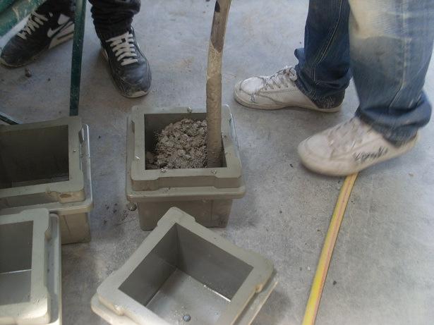
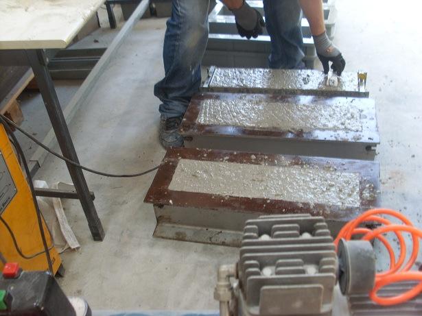
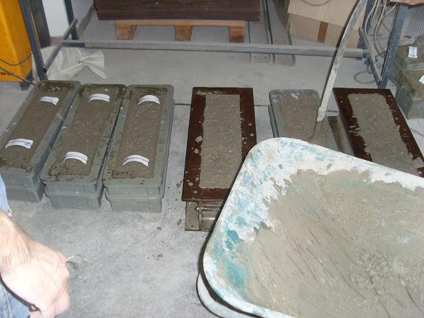
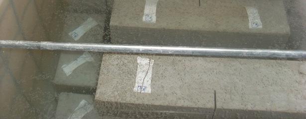
28 then the specimens have been cured under water during 28 days
29 2nd Workshop - The new boundaries of structural concrete Università Politecnica delle Marche September, 15-16, compressive strength@mpad Rcm (MPa) compressive strength@mpad Compressive strength f cube-28 (EN 206-1) L % white % compressive strength@mpad LS 50 compressivestrength@mpad S % 10 white 0.5 % S LS LS50-05 L75-05 L S100-1 S75-1 LS50-1 S 100L75-1 L white SFRC % white 0.5 % Ç 1.0 % white 0.5 % e e e compressivestrength@mpad e 1.0 % white 0.5 % e


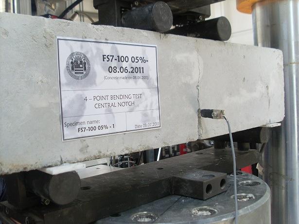
30 UNI Part II: Test method for determining the First Crack Strength and The Ductility Indexes
31 applied Experimental graphics: P CTODm 28 days L % redo the paste L100 1% 0.5% D flexurale Strength [kn] applied L75 applied LS50 applied % % 0.5% applied S % 0.5% D S100 REF S S75-05 LS50-05 L75-05 L S100-1 S75-1 LS50-1 L75-1 L100-1 [kn] D 0.5% 1.0 % 0.5% D D
32 Conclusions A numerical model based on the described interface elements has been presented in the present work. The model is particularly suited to model the stress-strain behavior of FRC in tension, capturing the fiber effect in bridging the crack opening, by means of two main mechanisms, such as bonding strength and dowel action in axial and transverse direction, respectively. Discontinuous interface approach is particularly suitable for mesoscale failure. The numerical simulations, presented in this work, may conclude that the constitutive proposals mainly capture the fundamental behaviors of fibrous concretes. Further are required.
33 Thank you for your attention Visit us in Salerno
CHAPTER 3 EXPERIMENTAL STUDY
 Experimental Study 42 CHAPTER 3 EXPERIMENTAL STUDY 3.1. INTRODUCTION The experimental study that has been carried out in this thesis has two main objectives: 1. Characterise the concrete behaviour in mode
Discrete Element Modelling of a Reinforced Concrete Structure
 Discrete Element Modelling of a Reinforced Concrete Structure S. Hentz, L. Daudeville, F.-V. Donzé Laboratoire Sols, Solides, Structures, Domaine Universitaire, BP 38041 Grenoble Cedex 9 France sebastian.hentz@inpg.fr
MODELLING NON-LINEAR BEHAVIOUR OF STEEL FIBRE REINFORCED CONCRETE
 6th RILEM Symposium on Fibre-Reinforced Concretes (FRC) - BEFIB - September, Varenna, Italy MODELLING NON-LINEAR BEHAVIOUR OF STEEL FIBRE REINFORCED CONCRETE W. A. Elsaigh, J. M. Robberts and E.P. Kearsley
MESO- AND MACROSCOPIC MODELS TO SIMULATE THE MECHANICAL BEHAVIOR OF FIBER REINFORCED CONCRETE COMPOSITES
 Mecánica Computacional Vol XXX, págs. 597-609 (artículo completo) Oscar Möller, Javier W. Signorelli, Mario A. Storti (Eds.) Rosario, Argentina, 1-4 Noviembre 2011 MESO- AND MACROSCOPIC MODELS TO SIMULATE
MODELING GEOMATERIALS ACROSS SCALES
 MODELING GEOMATERIALS ACROSS SCALES JOSÉ E. ANDRADE DEPARTMENT OF CIVIL AND ENVIRONMENTAL ENGINEERING AFOSR WORKSHOP ON PARTICULATE MECHANICS JANUARY 2008 COLLABORATORS: DR XUXIN TU AND MR KIRK ELLISON
THE BEHAVIOUR OF REINFORCED CONCRETE AS DEPICTED IN FINITE ELEMENT ANALYSIS.
 THE BEHAVIOUR OF REINFORCED CONCRETE AS DEPICTED IN FINITE ELEMENT ANALYSIS. THE CASE OF A TERRACE UNIT. John N Karadelis 1. INTRODUCTION. Aim to replicate the behaviour of reinforced concrete in a multi-scale
Failure behavior modeling of slender reinforced concrete columns subjected to eccentric load
 520 Failure behavior modeling of slender reinforced concrete columns subjected to eccentric load Abstract This work presents a numerical model to simulate the failure behavior of slender reinforced concrete
Entrance exam Master Course
 - 1 - Guidelines for completion of test: On each page, fill in your name and your application code Each question has four answers while only one answer is correct. o Marked correct answer means 4 points
Finite Element Method in Geotechnical Engineering
 Finite Element Method in Geotechnical Engineering Short Course on + Dynamics Boulder, Colorado January 5-8, 2004 Stein Sture Professor of Civil Engineering University of Colorado at Boulder Contents Steps
EDEM DISCRETIZATION (Phase II) Normal Direction Structure Idealization Tangential Direction Pore spring Contact spring SPRING TYPES Inner edge Inner d
 Normal Direction Structure Idealization Tangential Direction Pore spring Contact spring SPRING TYPES Inner edge Inner d") Institute of Industrial Science, University of Tokyo Bulletin of ERS, No. 48 (5) A TWO-PHASE SIMPLIFIED COLLAPSE ANALYSIS OF RC BUILDINGS PHASE : SPRING NETWORK PHASE Shanthanu RAJASEKHARAN, Muneyoshi
Institute of Industrial Science, University of Tokyo Bulletin of ERS, No. 48 (5) A TWO-PHASE SIMPLIFIED COLLAPSE ANALYSIS OF RC BUILDINGS PHASE : SPRING NETWORK PHASE Shanthanu RAJASEKHARAN, Muneyoshi
An orthotropic damage model for crash simulation of composites
 High Performance Structures and Materials III 511 An orthotropic damage model for crash simulation of composites W. Wang 1, F. H. M. Swartjes 1 & M. D. Gan 1 BU Automotive Centre of Lightweight Structures
Limit analysis of brick masonry shear walls with openings under later loads by rigid block modeling
 Limit analysis of brick masonry shear walls with openings under later loads by rigid block modeling F. Portioli, L. Cascini, R. Landolfo University of Naples Federico II, Italy P. Foraboschi IUAV University,
University of Sheffield The development of finite elements for 3D structural analysis in fire
 The development of finite elements for 3D structural analysis in fire Chaoming Yu, I. W. Burgess, Z. Huang, R. J. Plank Department of Civil and Structural Engineering StiFF 05/09/2006 3D composite structures
EQUIVALENT FRACTURE ENERGY CONCEPT FOR DYNAMIC RESPONSE ANALYSIS OF PROTOTYPE RC GIRDERS
 EQUIVALENT FRACTURE ENERGY CONCEPT FOR DYNAMIC RESPONSE ANALYSIS OF PROTOTYPE RC GIRDERS Abdul Qadir Bhatti 1, Norimitsu Kishi 2 and Khaliq U Rehman Shad 3 1 Assistant Professor, Dept. of Structural Engineering,
Nonlinear FE Analysis of Reinforced Concrete Structures Using a Tresca-Type Yield Surface
 Transaction A: Civil Engineering Vol. 16, No. 6, pp. 512{519 c Sharif University of Technology, December 2009 Research Note Nonlinear FE Analysis of Reinforced Concrete Structures Using a Tresca-Type Yield
EFFECT OF SHEAR REINFORCEMENT ON FAILURE MODE OF RC BRIDGE PIERS SUBJECTED TO STRONG EARTHQUAKE MOTIONS
 EFFECT OF SHEAR REINFORCEMENT ON FAILURE MODE OF RC BRIDGE PIERS SUBJECTED TO STRONG EARTHQUAKE MOTIONS Atsuhiko MACHIDA And Khairy H ABDELKAREEM SUMMARY Nonlinear D FEM was utilized to carry out inelastic
A FINITE ELEMENT MODEL FOR SIZE EFFECT AND HETEROGENEITY IN CONCRETE STRUCTURES
 A FINITE ELEMENT MODEL FOR SIZE EFFECT AND HETEROGENEITY IN CONCRETE STRUCTURES Roque Luiz Pitangueira 1 and Raul Rosas e Silva 2 1 Department of Structural Engineering -Federal University of Minas Gerais
REGRESSION MODELING FOR STRENGTH AND TOUGHNESS EVALUATION OF HYBRID FIBRE REINFORCED CONCRETE
 REGRESSION MODELING FOR STRENGTH AND TOUGHNESS EVALUATION OF HYBRID FIBRE REINFORCED CONCRETE S. Eswari 1, P. N. Raghunath and S. Kothandaraman 1 1 Department of Civil Engineering, Pondicherry Engineering
UNIVERSITY OF SASKATCHEWAN ME MECHANICS OF MATERIALS I FINAL EXAM DECEMBER 13, 2008 Professor A. Dolovich
 UNIVERSITY OF SASKATCHEWAN ME 313.3 MECHANICS OF MATERIALS I FINAL EXAM DECEMBER 13, 2008 Professor A. Dolovich A CLOSED BOOK EXAMINATION TIME: 3 HOURS For Marker s Use Only LAST NAME (printed): FIRST
Numerical Characterization of Concrete Heterogeneity
 Vol. Materials 5, No. Research, 3, 2002Vol. 5, No. 3, Statistical 309-314, 2002. Characterization of the Concrete Numerical Modeling of Size Effect In Heterogeneity 2002 309 Numerical Characterization
POST-PEAK BEHAVIOR OF FRP-JACKETED REINFORCED CONCRETE COLUMNS
 POST-PEAK BEHAVIOR OF FRP-JACKETED REINFORCED CONCRETE COLUMNS - Technical Paper - Tidarut JIRAWATTANASOMKUL *1, Dawei ZHANG *2 and Tamon UEDA *3 ABSTRACT The objective of this study is to propose a new
Modeling of Interfacial Debonding Induced by IC Crack for Concrete Beam-bonded with CFRP
 Proceedings of the World Congress on Engineering 21 Vol II WCE 21, June 2 - July 1, 21, London, U.K. Modeling of Interfacial Debonding Induced by IC Crack for Concrete Beam-bonded with CFRP Lihua Huang,
MODELING GEOMATERIALS ACROSS SCALES JOSÉ E. ANDRADE DEPARTMENT OF CIVIL AND ENVIRONMENTAL ENGINEERING EPS SEMINAR SERIES MARCH 2008
 MODELING GEOMATERIALS ACROSS SCALES JOSÉ E. ANDRADE DEPARTMENT OF CIVIL AND ENVIRONMENTAL ENGINEERING EPS SEMINAR SERIES MARCH 2008 COLLABORATORS: DR XUXIN TU AND MR KIRK ELLISON THE ROADMAP MOTIVATION
5 ADVANCED FRACTURE MODELS
 Essentially, all models are wrong, but some are useful George E.P. Box, (Box and Draper, 1987) 5 ADVANCED FRACTURE MODELS In the previous chapter it was shown that the MOR parameter cannot be relied upon
FRACTURE IN HIGH PERFORMANCE FIBRE REINFORCED CONCRETE PAVEMENT MATERIALS
 FRACTURE IN HIGH PERFORMANCE FIBRE REINFORCED CONCRETE PAVEMENT MATERIALS ERIK DENNEMAN A thesis submitted in partial fulfilment of the requirements for the degree of PHILOSOPHIAE DOCTOR (ENGINEERING)
Role of Force Resultant Interaction on Ultra-High Performance Concrete
 First International Interactive Symposium on UHPC 216 Role of Force Resultant Interaction on Ultra-High Performance Concrete Author(s) & Affiliation: Titchenda Chan (1), Kevin R. Mackie (1), and Jun Xia
Experimentally Calibrating Cohesive Zone Models for Structural Automotive Adhesives
 Experimentally Calibrating Cohesive Zone Models for Structural Automotive Adhesives Mark Oliver October 19, 2016 Adhesives and Sealants Council Fall Convention contact@veryst.com www.veryst.com Outline
GEOSYNTHETICS ENGINEERING: IN THEORY AND PRACTICE
 GEOSYNTHETICS ENGINEERING: IN THEORY AND PRACTICE Prof. J. N. Mandal Department of Civil Engineering, IIT Bombay, Powai, Mumbai 400076, India. Tel.022-25767328 email: cejnm@civil.iitb.ac.in Module-13 LECTURE-
EMA 3702 Mechanics & Materials Science (Mechanics of Materials) Chapter 2 Stress & Strain - Axial Loading
 Chapter 2 Stress & Strain - Axial Loading") MA 3702 Mechanics & Materials Science (Mechanics of Materials) Chapter 2 Stress & Strain - Axial Loading MA 3702 Mechanics & Materials Science Zhe Cheng (2018) 2 Stress & Strain - Axial Loading Statics
MA 3702 Mechanics & Materials Science (Mechanics of Materials) Chapter 2 Stress & Strain - Axial Loading MA 3702 Mechanics & Materials Science Zhe Cheng (2018) 2 Stress & Strain - Axial Loading Statics
MODELING OF NONLINEAR BEHAVIOR OF RC SHEAR WALLS UNDER COMBINED AXIAL, SHEAR AND FLEXURAL LOADING
 CD02-003 MODELING OF NONLINEAR BEHAVIOR OF RC SHEAR WALLS UNDER COMBINED AXIAL, SHEAR AND FLEXURAL LOADING B. Ghiassi 1, M. Soltani 2, A. A. Tasnimi 3 1 M.Sc. Student, School of Engineering, Tarbiat Modares
CFRP. FRP FRP. Abaqus
 C Epoxy C baqus C FE baqus C amene.kia@gmail.com EROG 1 Debonding : / C (mm) E c (MPa) f' c (MPa) f' t (MPa) a S L d h b 1 2 3 1 2 3 baqus C Leong Kok Leong Kok CDP E p (GPa) (MPa) E a (MPa) G a (MPa)
Using the Timoshenko Beam Bond Model: Example Problem
 Using the Timoshenko Beam Bond Model: Example Problem Authors: Nick J. BROWN John P. MORRISSEY Jin Y. OOI School of Engineering, University of Edinburgh Jian-Fei CHEN School of Planning, Architecture and
MATERIALS FOR CIVIL AND CONSTRUCTION ENGINEERS
 MATERIALS FOR CIVIL AND CONSTRUCTION ENGINEERS 3 rd Edition Michael S. Mamlouk Arizona State University John P. Zaniewski West Virginia University Solution Manual FOREWORD This solution manual includes
DESIGN OF DOWELS FOR SHEAR TRANSFER AT THE INTERFACE BETWEEN CONCRETE CAST AT DIFFERENT TIMES: A CASE STUDY
 DESIGN OF DOWELS FOR SHEAR TRANSFER AT THE INTERFACE BETWEEN CONCRETE CAST AT DIFFERENT TIMES: A CASE STUDY Samayamanthree Mudiyanselage Premasiri Karunarathna 118614J Degree of Master of Engineering in
Modeling the bond of GFRP and concrete based on a damage evolution approach
 Modeling the ond of GFRP and concrete ased on a damage evolution approach Mohammadali Rezazadeh 1, Valter Carvelli 2, and Ana Veljkovic 3 1 Dep. Architecture, Built environment and Construction engineering,
Heterogeneous structures studied by interphase elasto-damaging model.
 Heterogeneous structures studied by interphase elasto-damaging model. Giuseppe Fileccia Scimemi 1, Giuseppe Giambanco 1, Antonino Spada 1 1 Department of Civil, Environmental and Aerospace Engineering,
Hardened Concrete. Lecture No. 16
 Hardened Concrete Lecture No. 16 Fatigue strength of concrete Modulus of elasticity, Creep Shrinkage of concrete Stress-Strain Plot of Concrete At stress below 30% of ultimate strength, the transition
Durability of Steel Fiber Reinforced Concrete Filled Steel Tubes under Eccentric Loads
 Durability of Steel Fiber Reinforced Concrete Filled Steel Tubes under Eccentric Loads Eltobgy, H. H. 1,*, Abdallah, S. 1, and Shaaban, I. 1 1 Civil Engineering Department, Faculty of Eng. at Shoubra,
Chapter 5 Elastic Strain, Deflection, and Stability 1. Elastic Stress-Strain Relationship
 Chapter 5 Elastic Strain, Deflection, and Stability Elastic Stress-Strain Relationship A stress in the x-direction causes a strain in the x-direction by σ x also causes a strain in the y-direction & z-direction
EVALUATION OF NONLOCAL APPROACHES FOR MODELLING FRACTURE IN NOTCHED CONCRETE SPECIMENS
 VIII International Conference on Fracture Mechanics of Concrete and Concrete Structures FraMCoS-8 J.G.M. Van Mier, G. Ruiz, C. Andrade, R.C. Yu and X.X. Zhang (Eds) EVALUATION OF NONLOCAL APPROACHES FOR
Cracking in Quasi-Brittle Materials Using Isotropic Damage Mechanics
 Cracking in Quasi-Brittle Materials Using Isotropic Damage Mechanics Tobias Gasch, PhD Student Co-author: Prof. Anders Ansell Comsol Conference 2016 Munich 2016-10-12 Contents Introduction Isotropic damage
ULTIMATE SHEAR OF BEAMS STRENGTHENED WITH CFRP SHEETS
 ULTIMATE SHEAR OF BEAMS STRENGTHENED WITH CFRP SHEETS U. Ianniruberto and M. Imbimbo Department of Civil Engineering, University of Rome Tor Vergata Via di Tor Vergata 0, 0033, Rome, Italy SUMMARY: The
Fig. 1. Different locus of failure and crack trajectories observed in mode I testing of adhesively bonded double cantilever beam (DCB) specimens.
 specimens.") a). Cohesive Failure b). Interfacial Failure c). Oscillatory Failure d). Alternating Failure Fig. 1. Different locus of failure and crack trajectories observed in mode I testing of adhesively bonded double
a). Cohesive Failure b). Interfacial Failure c). Oscillatory Failure d). Alternating Failure Fig. 1. Different locus of failure and crack trajectories observed in mode I testing of adhesively bonded double
Bending Load & Calibration Module
 Bending Load & Calibration Module Objectives After completing this module, students shall be able to: 1) Conduct laboratory work to validate beam bending stress equations. 2) Develop an understanding of
Uncertainty modelling using software FReET
 Uncertainty modelling using software FReET D. Novak, M. Vorechovsky, R. Rusina Brno University of Technology Brno, Czech Republic 1/30 Outline Introduction Methods and main features Software FReET Selected
Dynamic Analysis of a Reinforced Concrete Structure Using Plasticity and Interface Damage Models
 Dynamic Analysis of a Reinforced Concrete Structure Using Plasticity and Interface Damage Models I. Rhee, K.J. Willam, B.P. Shing, University of Colorado at Boulder ABSTRACT: This paper examines the global
Finite element analysis of diagonal tension failure in RC beams
 Finite element analysis of diagonal tension failure in RC beams T. Hasegawa Institute of Technology, Shimizu Corporation, Tokyo, Japan ABSTRACT: Finite element analysis of diagonal tension failure in a
Civil Engineering Design (1) Design of Reinforced Concrete Columns 2006/7
 Design of Reinforced Concrete Columns 2006/7") Civil Engineering Design (1) Design of Reinforced Concrete Columns 2006/7 Dr. Colin Caprani, Chartered Engineer 1 Contents 1. Introduction... 3 1.1 Background... 3 1.2 Failure Modes... 5 1.3 Design Aspects...
Civil Engineering Design (1) Design of Reinforced Concrete Columns 2006/7 Dr. Colin Caprani, Chartered Engineer 1 Contents 1. Introduction... 3 1.1 Background... 3 1.2 Failure Modes... 5 1.3 Design Aspects...
Optimal Slope of Dramix Type Fibers in Reinforced Concrete
 6 th World Congresses of Structural and Multidisciplinary Optimization Rio de Janeiro, 3 May - 3 June 25, Brazil Optimal Slope of Dramix Type Fibers in Reinforced Concrete P. Prochazka 1, N. Starikov 2
Mesoscopic Simulation of Failure of Mortar and Concrete by 3D RBSM
 Journal of Advanced Concrete Technology Vol., No., 85-4, October 5 / Copyright 5 Japan Concrete Institute 85 Scientific paper Mesoscopic Simulation of Failure of Mortar and Concrete by D RBSM Kohei Nagai,
MECE 3321 MECHANICS OF SOLIDS CHAPTER 3
 MECE 3321 MECHANICS OF SOLIDS CHAPTER 3 Samantha Ramirez TENSION AND COMPRESSION TESTS Tension and compression tests are used primarily to determine the relationship between σ avg and ε avg in any material.
EFFECT OF THE TEST SET-UP ON FRACTURE MECHANICAL PARAMETERS OF CONCRETE
 Fracture Mechanics of Concrete Structures Proceedings FRAMCOS-3 AEDIFICATIO Publishers, D-79104 Freiburg, Germany EFFECT OF THE TEST SET-UP ON FRACTURE MECHANICAL PARAMETERS OF CONCRETE V. Mechtcherine
Homework No. 1 MAE/CE 459/559 John A. Gilbert, Ph.D. Fall 2004
 Homework No. 1 MAE/CE 459/559 John A. Gilbert, Ph.D. 1. A beam is loaded as shown. The dimensions of the cross section appear in the insert. the figure. Draw a complete free body diagram showing an equivalent
FLEXURAL MODELLING OF STRAIN SOFTENING AND STRAIN HARDENING FIBER REINFORCED CONCRETE
 Proceedings, Pro. 53, S.A.R.L., Cachan, France, pp.55-6, 7. FLEXURAL MODELLING OF STRAIN SOFTENING AND STRAIN HARDENING FIBER REINFORCED CONCRETE Chote Soranakom and Barzin Mobasher Department of Civil
Abstract. 1 Introduction
 Contact analysis for the modelling of anchors in concrete structures H. Walter*, L. Baillet** & M. Brunet* *Laboratoire de Mecanique des Solides **Laboratoire de Mecanique des Contacts-CNRS UMR 5514 Institut
Numerical analysis of the mechanical response of wood glulam beams reinforced through the thickness by FRP rods.
 Numerical analysis of the mechanical response of wood glulam beams reinforced through the thickness by FRP rods. Giuseppe Giambanco 1, Tiziana Turetta 1, Alessia Cottone 1 1 Department of Structural, Aerospace
Numerical Modelling of Blockwork Prisms Tested in Compression Using Finite Element Method with Interface Behaviour
 13 th International Brick and Block Masonry Conference Amsterdam, July 4-7, 2004 Numerical Modelling of Blockwork Prisms Tested in Compression Using Finite Element Method with Interface Behaviour H. R.
NUMERICAL SIMULATION OF CONCRETE EXPOSED TO HIGH TEMPERATURE DAMAGE AND EXPLOSIVE SPALLING
 NUMERICAL SIMULATION OF CONCRETE EXPOSED TO HIGH TEMPERATURE DAMAGE AND EXPLOSIVE SPALLING Prof. Joško Ožbolt 1 Josipa Bošnjak 1, Goran Periškić 1, Akanshu Sharma 2 1 Institute of Construction Materials,
Model for predicting the UHPFRC tensile hardening response
 UHPC-2008: The Second International Symposium on Ultra High Performance Concrete, March 05-07, 2008, Kassel, Germany. John Wuest Dr., Civil Engineer Ecole Polytechnique Fédérale de Lausanne Lausanne, Switzerland
Fracture Test & Fracture Parameters of Self Compacting Concrete using ANSYS. Zeel Vashi 1,Megha Thomas 2 I. INTRODUCTION
 International Journal of Technical Innovation in Modern Engineering & Science (IJTIMES) Impact Factor: 3.45 (SJIF-2015), e-issn: 2455-2584 Volume 3, Issue 05, May-2017 Fracture Test & Fracture Parameters
Influence of bond-slip on the behaviour of reinforced concrete beam to column joints
 Tailor Made Concrete Structures Walraven & Stoelhorst (eds) 2008 Taylor & Francis Group, London, ISBN 978-0-415-47535-8 Influence of bond-slip on the behaviour of reinforced concrete beam to column joints
SIZE EFFECT ANALYSIS OF COMPRESSIVE STRENGTH FOR RECYCLED CONCRETE USING THE BFEM ON MICROMECHANICS
 Proceedings of the 6th International Conference on Mechanics and Materials in Design, Editors: J.F. Silva Gomes & S.A. Meguid, P.Delgada/Azores, 6-3 July 5 PAPER REF: 54 SIZE EFFECT ANALYSIS OF COMPRESSIVE
Failure interaction curves for combined loading involving torsion, bending, and axial loading
 Failure interaction curves for combined loading involving torsion, bending, and axial loading W M Onsongo Many modern concrete structures such as elevated guideways are subjected to combined bending, torsion,
Finite Element Analysis of FRP Debonding Failure at the Tip of Flexural/Shear Crack in Concrete Beam
 Marquette University e-publications@marquette Civil and Environmental Engineering Faculty Research and Publications Civil and Environmental Engineering, Department of 12-1-2013 Finite Element Analysis
Finite Element Modelling with Plastic Hinges
 01/02/2016 Marco Donà Finite Element Modelling with Plastic Hinges 1 Plastic hinge approach A plastic hinge represents a concentrated post-yield behaviour in one or more degrees of freedom. Hinges only
Experimental Study on the Damage Evolution of Rebar-Concrete Interface. Lu Xinzheng
 Experimental Study on the Damage Evolution of Rebar-Concrete Interface Lu Xinzheng SCHOOL OF CIVIL AND STRUCTURAL ENGINEERING NANYANG TECHNOLOGICAL UNIVERSITY 1999/ ABSTRACT In reinforced concrete structures,
Introduction and Background
 Introduction and Background Itasca Consulting Group, Inc. (Itasca) has been participating in the geomechanical design of the underground 118-Zone at the Capstone Minto Mine (Minto) in the Yukon, in northwestern
Fracture Mechanics of Non-Shear Reinforced R/C Beams
 Irina Kerelezova Thomas Hansen M. P. Nielsen Fracture Mechanics of Non-Shear Reinforced R/C Beams DANMARKS TEKNISKE UNIVERSITET Report BYG DTU R-154 27 ISSN 161-2917 ISBN 97887-7877-226-5 Fracture Mechanics
MESOSCOPIC MODELLING OF MASONRY USING GFEM: A COMPARISON OF STRONG AND WEAK DISCONTINUITY MODELS B. Vandoren 1,2, K. De Proft 2
 Blucher Mechanical Engineering Proceedings May 2014, vol. 1, num. 1 www.proceedings.blucher.com.br/evento/10wccm MESOSCOPIC MODELLING OF MASONRY USING GFEM: A COMPARISON OF STRONG AND WEAK DISCONTINUITY
Chapter. Materials. 1.1 Notations Used in This Chapter
 Chapter 1 Materials 1.1 Notations Used in This Chapter A Area of concrete cross-section C s Constant depending on the type of curing C t Creep coefficient (C t = ε sp /ε i ) C u Ultimate creep coefficient
NUMERICAL SIMULATION OF THE INELASTIC SEISMIC RESPONSE OF RC STRUCTURES WITH ENERGY DISSIPATORS
 NUMERICAL SIMULATION OF THE INELASTIC SEISMIC RESPONSE OF RC STRUCTURES WITH ENERGY DISSIPATORS ABSTRACT : P Mata1, AH Barbat1, S Oller1, R Boroschek2 1 Technical University of Catalonia, Civil Engineering
Mechanics of Earthquakes and Faulting
 Mechanics of Earthquakes and Faulting www.geosc.psu.edu/courses/geosc508 Surface and body forces Tensors, Mohr circles. Theoretical strength of materials Defects Stress concentrations Griffith failure
An Energy Dissipative Constitutive Model for Multi-Surface Interfaces at Weld Defect Sites in Ultrasonic Consolidation
 An Energy Dissipative Constitutive Model for Multi-Surface Interfaces at Weld Defect Sites in Ultrasonic Consolidation Nachiket Patil, Deepankar Pal and Brent E. Stucker Industrial Engineering, University
**********************************************************************
 Department of Civil and Environmental Engineering School of Mining and Petroleum Engineering 3-33 Markin/CNRL Natural Resources Engineering Facility www.engineering.ualberta.ca/civil Tel: 780.492.4235
NORMAL STRESS. The simplest form of stress is normal stress/direct stress, which is the stress perpendicular to the surface on which it acts.
 NORMAL STRESS The simplest form of stress is normal stress/direct stress, which is the stress perpendicular to the surface on which it acts. σ = force/area = P/A where σ = the normal stress P = the centric
SHEAR RESISTANCE BETWEEN CONCRETE-CONCRETE SURFACES
 , DOI: 10.2478/sjce-2013-0018 M. KOVAČOVIC SHEAR RESISTANCE BETWEEN CONCRETE-CONCRETE SURFACES Marek KOVAČOVIC Email: marek.kovacovic@gmail.com Research field: composite structures Address: Department
3D Finite Element analysis of stud anchors with large head and embedment depth
 3D Finite Element analysis of stud anchors with large head and embedment depth G. Periškić, J. Ožbolt & R. Eligehausen Institute for Construction Materials, University of Stuttgart, Stuttgart, Germany
Microplane Model formulation ANSYS, Inc. All rights reserved. 1 ANSYS, Inc. Proprietary
 Microplane Model formulation 2010 ANSYS, Inc. All rights reserved. 1 ANSYS, Inc. Proprietary Table of Content Engineering relevance Theory Material model input in ANSYS Difference with current concrete
NUMERICAL SIMULATIONS OF CORNERS IN RC FRAMES USING STRUT-AND-TIE METHOD AND CDP MODEL
 Numerical simulations of corners in RC frames using Strut-and-Tie Method and CDP model XIII International Conference on Computational Plasticity. Fundamentals and Applications COMPLAS XIII E. Oñate, D.R.J.
DYNAMIC ANALYSIS OF PILES IN SAND BASED ON SOIL-PILE INTERACTION
 October 1-17,, Beijing, China DYNAMIC ANALYSIS OF PILES IN SAND BASED ON SOIL-PILE INTERACTION Mohammad M. Ahmadi 1 and Mahdi Ehsani 1 Assistant Professor, Dept. of Civil Engineering, Geotechnical Group,
MODELING OF THE WEDGE SPLITTING TEST USING AN EXTENDED CRACKED HINGE MODEL
 Engineering MECHANICS, Vol. 21, 2014, No. 1, p. 67 72 67 MODELING OF THE WEDGE SPLITTING TEST USING AN EXTENDED CRACKED HINGE MODEL Tomáš Pail, Petr Frantík* The present paper describes a semi-analytical
Railroad Concrete Tie Failure Analysis
 Railroad Concrete Tie Failure Analysis Hailing Yu, David Jeong, Brian Marquis, and Michael Coltman 2014 International Crosstie & Fastening System Symposium June 3-5, 2014 The National Transportation Systems
Finite Element Modeling of the Load Transfer Mechanism in Adjacent Prestressed. Concrete Box-Beams. a thesis presented to.
 Finite Element Modeling of the Load Transfer Mechanism in Adjacent Prestressed Concrete Box-Beams a thesis presented to the faculty of the Russ College of Engineering and Technology of Ohio University
EFFECTS OF CONFINED CONCRETE MODELS ON SIMULATING RC COLUMNS UNDER LOW-CYCLIC LOADING
 13 th World Conference on Earthquake Engineering Vancouver, B.C., Canada August 1-6, 2004 Paper No. 1498 EFFECTS OF CONFINED CONCRETE MODELS ON SIMULATING RC COLUMNS UNDER LOW-CYCLIC LOADING Zongming HUANG
MASONRY MICRO-MODELLING ADOPTING A DISCONTINUOUS FRAMEWORK
 MASONRY MICRO-MODELLING ADOPTING A DISCONTINUOUS FRAMEWORK J. Pina-Henriques and Paulo B. Lourenço School of Engineering, University of Minho, Guimarães, Portugal Abstract Several continuous and discontinuous
Mechanical Engineering Ph.D. Preliminary Qualifying Examination Solid Mechanics February 25, 2002
 student personal identification (ID) number on each sheet. Do not write your name on any sheet. #1. A homogeneous, isotropic, linear elastic bar has rectangular cross sectional area A, modulus of elasticity
Computational model for post cracking analysis of RC membrane elements based on local stress strain characteristics
 Engineering Structures 5 (003) 993 1007 www.elsevier.com/locate/engstruct Computational model for post cracking analysis of RC membrane elements based on local stress strain characteristics Masoud Soltani
Lab Exercise #5: Tension and Bending with Strain Gages
 Lab Exercise #5: Tension and Bending with Strain Gages Pre-lab assignment: Yes No Goals: 1. To evaluate tension and bending stress models and Hooke s Law. a. σ = Mc/I and σ = P/A 2. To determine material
ALGORITHM FOR NON-PROPORTIONAL LOADING IN SEQUENTIALLY LINEAR ANALYSIS
 9th International Conference on Fracture Mechanics of Concrete and Concrete Structures FraMCoS-9 Chenjie Yu, P.C.J. Hoogenboom and J.G. Rots DOI 10.21012/FC9.288 ALGORITHM FOR NON-PROPORTIONAL LOADING
Introduction to Engineering Materials ENGR2000. Dr. Coates
 Introduction to Engineering Materials ENGR2 Chapter 6: Mechanical Properties of Metals Dr. Coates 6.2 Concepts of Stress and Strain tension compression shear torsion Tension Tests The specimen is deformed
Chapter 7. Highlights:
 Chapter 7 Highlights: 1. Understand the basic concepts of engineering stress and strain, yield strength, tensile strength, Young's(elastic) modulus, ductility, toughness, resilience, true stress and true
MECHANICS OF MATERIALS Sample Problem 4.2
 Sample Problem 4. SOLUTON: Based on the cross section geometry, calculate the location of the section centroid and moment of inertia. ya ( + Y Ad ) A A cast-iron machine part is acted upon by a kn-m couple.
Bond-Slip Characteristics between Cold-Formed Metal and Concrete
 Missouri University of Science and Technology Scholars' Mine International Specialty Conference on Cold- Formed Steel Structures (2014) - 22nd International Specialty Conference on Cold-Formed Steel Structures
Sabah Shawkat Cabinet of Structural Engineering Walls carrying vertical loads should be designed as columns. Basically walls are designed in
 Sabah Shawkat Cabinet of Structural Engineering 17 3.6 Shear walls Walls carrying vertical loads should be designed as columns. Basically walls are designed in the same manner as columns, but there are
6.4 A cylindrical specimen of a titanium alloy having an elastic modulus of 107 GPa ( psi) and
 and") 6.4 A cylindrical specimen of a titanium alloy having an elastic modulus of 107 GPa (15.5 10 6 psi) and an original diameter of 3.8 mm (0.15 in.) will experience only elastic deformation when a tensile
6.4 A cylindrical specimen of a titanium alloy having an elastic modulus of 107 GPa (15.5 10 6 psi) and an original diameter of 3.8 mm (0.15 in.) will experience only elastic deformation when a tensile
IMPACT RESPONSE ANALYSIS OF LARGE SCALE RC GIRDER WITH SAND CUSHION
 -Technical Paper- IMPACT RESPONSE ANALYSIS OF LARGE SCALE RC GIRDER WITH SAND CUSHION Abdul Qadir BHATTI *1, Norimitsu KISHI *2, Shin-ya OKADA *3 and Hisashi KONNO *4 ABSTRACT In order to establish a proper
Mechanical Properties of Materials
 Mechanical Properties of Materials Strains Material Model Stresses Learning objectives Understand the qualitative and quantitative description of mechanical properties of materials. Learn the logic of
CE 221: MECHANICS OF SOLIDS I CHAPTER 1: STRESS. Dr. Krisada Chaiyasarn Department of Civil Engineering, Faculty of Engineering Thammasat university
 CE 221: MECHANICS OF SOLIDS I CHAPTER 1: STRESS By Dr. Krisada Chaiyasarn Department of Civil Engineering, Faculty of Engineering Thammasat university Agenda Introduction to your lecturer Introduction
Particle flow simulation of sand under biaxial test
 5th International Conference on Civil Engineering and Transportation (ICCET 2015) Particle flow simulation of sand under biaxial test Xiao-li Dong1,2, a *,Wei-hua Zhang1,a 1 Beijing City University, China
CHAPTER 4: BENDING OF BEAMS
 (74) CHAPTER 4: BENDING OF BEAMS This chapter will be devoted to the analysis of prismatic members subjected to equal and opposite couples M and M' acting in the same longitudinal plane. Such members are