ANALYSIS OF TOUCH-DOWN DYNAMICS AND SAMPLING SEQUENCE OF MUSES-C
|
|
|
- Cora Spencer
- 5 years ago
- Views:
Transcription
1 ANALYSIS OF TOUCH-DOWN DYNAMICS AND SAMPLING SEQUENCE OF MUSES-C Kazuya Yoshida 1 Yoichi Nishimaki 1 Hiroshi Kawabe 1 Takashi Kubota 2 1 Dept. of Aeronautics and Space Engineering, Tohoku University, Aoba 01, Sendai, , Japan 2 The Institute of Space and Astronautical Science, 3-1-1, Yoshinodai, Sagamihara, , Japan ABSTRACT The Institute of Space and Astronautical Science, Japan (ISAS) is developing a spacecraft that obtains samples from the surface of an asteroid, then return to Earth. The spacecraft, named MUSES-C targets 1998SF36, one of near- Earth asteroids. Since the gravity of the asteroid is considerably small, the spacecraft will not be able to stand on its surface, and thus will have to acquire samples in a dynamic sequence. The touch-down behavior of the MUSES-C is studied based on the dynamics model of a multibody system with frictional contact. To verify the mathematical model, experiments with a miniature model have been carried out under the micro-gravity environment in a dropshaft facility, MGLAB. Full-scale experiments with the hardware components of the proto-flight model have been also carried out using the ISAS s robot simulator. Nominal and critical cases of the touch-down sampling are examined by comparing the results of experiment and numerical simulation. INTRODUCTION The Institute of Space and Astronautical Science, Japan (ISAS) launches an exploration robotic probe named MUSES-C toward 1998SF36, one of near earth objects, with [m] across. The mission MUSES-C is the world s first attempt of sample and return from an asteroid. Considering versatility to the micro-gravity of the asteroid s surface, and to unknown surface conditions such as flatness and hardness, the crush sampling and touch-and-go strategy is taken among various candidate strategies. The accepted strategy minimizes the physical contact with the surface of uncertainty, yet ensures the sample acquisition. The physical contact will be made at the endtip of a conical probe supported by a deployable compliant structure. During the contact, a projectile is projected inside the probe to crash the surface. The ejected fragments of the surface will be concentrated in the conical probe and collected in a sample chamber located at the top corner of the cone [1][2]. This touch-down sampling is one of the most critical events in the mission. If the strength of the probe structure is not enough, or the spacecraft tumbles over the surface, the mission will fail. Therefore it is very important to properly assess the impact forces at the contact and tumbling motion after the contact. For the understanding of the touch-down dynamics, including the impact and tumbling, we have carried out various experiments and numerical analyses. One of the experiments was with a drop-shaft facility to have physical micro-gravity environment, and the contact behavior was studied using a miniature model of the spacecraft. Another experiment was hardware verification with a full-scale proto-flight model of the sampling probe using a mechanical motion simulator to represent the relative motion between the probe and the surface [3]. This paper summarizes the study on this unique strategy of touch-and-go sampling, from initial discussion to final pre-flight assessments. The topics cover (1) a general discussion of possible strategies for sampling from a minor body, (2) modeling of the dynamics of the spacecraft including structural compliance and frictional contact, (3) experimental verification to understand the contact dynamics, and (4) detailed assessments on critical cases. SMPLING FROM A MINOR BODY Candidate Strategies Key consideration in the sampling on a minor body is versatility to micro-gravity and unknown hardness of the surface. As a general discussion, the following strategies are considered possible candidates (see Figure 1): (a) Anchor and Drill: Drilling is a common idea to obtain core samples from surface to interior. However to achieve the drilling, the spacecraft must be anchored firmly on the surface to accommodate the reaction (see Figure 1 (a)). Both drilling and anchoring will be easier on soft surface, such as the surface of a comet. ROSETTA, an European comet probe takes this strategy [4]. (b) Harpoon and Penetrator: Figure 1 (b) describes an idea to penetrate a sampling probe into the target 1
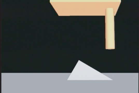
2 Figure 1: Variety of sampling strategies Figure 2: Sampling sequence of MUSES-C using its kinetic energy. If properly designed, samples will be packed in the penetrator, and if tethered they can be retrieved. In this strategy, the spacecraft needs hovering over the sampling site, but landing or touchdown is not needed. Hovering may be less critical than touch-down when without tether. But with tether, its deploy and retrieval becomes a challenging issue. (c)(d) Crash Sampling: If a bullet-like projectile is projected with certain velocity, the surface will be crashed and fragments are ejected. Then, one idea is to collect such fragments in an orbit (see Figure 1 (c)). The dust collection technology used in STARDUST mission [5] will be applied here. But as the distance between the crash and sampling sites is far away, the sample acquisition becomes uncertain and, even if obtained, it is difficult to distinguish the point where each fragment comes from. Another idea is to collect the crushed fragments on or at close vicinity of the surface, as shown in Figure 1 (d). In this option, the spacecraft is required to make physical contact with the surface although, if the projectile is projected inside a probe that has a conical shape, the ejected fragments will be deflected along the cone and concentrated at the top corner. With this strategy, samples are efficiently collected from a specific point of the surface. The strategy is applicable for a wide range of surface hardness from basalt, for example, to regolith. Also, since the sampling will be completed instantaneously, the time of the physical contact with the asteroid s surface can be short, then the sampling sequence will be like touch-and-go. Sampling Sequence of MUSES-C and Critical Issues From the above four candidates, the last strategy was chosen for MUSES-C and a number of tests have been carried out to make a detailed design. In the flight model, the projectile of 5 [g] is projected at 300 [m/s]. The test results show that several hundred milligrams to several grams of fragmented target materials can be collected by a single sampling action [6]. Figure 2 illustrates the sampling sequence. The spacecraft descends toward a specific point of the asteroid using a vision-based autonomous guidance system, so that the contact velocity is controlled within 0.1 [m/s] vertically and 0.08 [m/s] horizontally. The conical probe is supported by Double-reverse Helical Spring (DHS), a dedicated deployable structure with compliance. The length of this sampling device, termed Sampler Horn hereafter, is 1 [m]. Then the maximum clearance beneath the bottom of the spacecraft becomes less than 1 [m] during the sampling. Local obstacles that may interfere this clearance will be detected and avoided using optical sensors. Local inclination at the contact point of the sampler horn is assumed less than ± 30 [deg] as a design criteria. As soon as the contact is detected, the projectile is projected. The momentum of the projectile reaction is about 1.5 [Nms], which is negligible comparing to the momentum of the spacecraft itself that is about 40 [Nms]. However, the tumbling motion caused by the contact reaction through the sampler horn is much more critical, because the horn is mounted on the spacecraft with about 0.7 [m] of offset from its centroid. The DHS deforms during the contact. The magnitude of the deformation depends on stiffness of the spring and touch-down conditions. We need to check if the deformation is within an acceptable range. For example, if the projectile is projected after the horn tip is largely deformed, it may hit the horn itself but not the asteroid. After the sampling, gas-jet thrusters will be used to lift the spacecraft off the surface. As the spacecraft starts tumbling immediate after the contact, the delay of firing the lift-off thrusters will result in a critical situation. In order to be aware of such potential risks, the motion of the spacecraft for various touch-down and liftoff conditions is carefully examined in this paper. MATHEMATICAL MODEL Equation of Motion A schematic model of MUSES-C is illustrated in Figure 3. The spacecraft is modeled by a multibody system including compliant elements. The sampler horn is discretized into multiple rigid segments, so that each joint represents compliant characteristics in bending angle θ, axial and lateral deformation ɛ. The endtip of the horn receives the external force from the ground contact. The equation of motion of this system is given by the following equation. F e is a contact force applied at the endtip of the sampler horn. The deformation of the horn, that is made of a compliant structure, is described by ɛ and θ. where H v 0 ω 0 ɛ θ + c = F 0 N 0 f τ H : inertia tensor of the entire system + J T e F e (1) 2


 r + D w ( d) s (2) where we assume r = s = 1 for simplicity.")
3 Figure 3: A schematic model of MUSES-C (a) Double-reverse Helical Spring (b) axial deformation of DHS Figure 4: Model of the sampler horn (c) lateral deformation of DHS c : velocity dependent terms v 0 : velocity of the spacecraft base ω 0 : angular velocity of the spacecraft base F 0 : thruster force on the base N 0 : thruster moment on the base ɛ : axial and lateral deformation of DHS θ : bending angle of DHS f : axial and lateral force on DHS τ : bending moment on DHS J e : Jacobian matrix (a) experimental setup in the drop-shaft capsule (b) simulation model of the spacecraft with an offset probe, touching over an inclined surface Figure 5: MGLAB experiment for the study of contact dynamics in micro-g environment F e : ground contact force Contact Model The contact force F e is divided into a component perpendicular to the contact surface, F n, and a component tangent to it, F t. The magnitude of F n is modeled using a penetration depth into the surface, d: F n = K w (d) r + D w ( d) s (2) where we assume r = s = 1 for simplicity. F t is switched between static friction and kinetic friction using a threshold value µ 0 : For static friction (F t /F n <µ 0 ) F t = K t (d t ) r + D t ( d t ) s (3) For kinetic friction (F t /F n >µ 0 ) F t = µf n (4) Sampler Horn As introduced previously, double-reverse helical spring (DHS, see Figure 4 (a)) is used for the sampler horn. DHS shows high stiffness when it is fully stretched, but it shows compliance otherwise. For the sampler horn, the length of the DHS is constrained not to become fullstretch. The axial and lateral compliance of the sampler horn thus identified as shown in Figure 4 (b) and (c). The characteristics are nonlinear. EXPERIMENTAL VERIFICATION MGLAB Experiments The experiments using a miniature model were conducted in Micro-Gravity Laboratory of Japan (MGLAB), a drop-shaft facility providing 4.5 [s] duration of microgravity environment. In this series of experiments, the basic characteristics of the mathematical model with frictional contact and compliant probe were verified. Figure 5 (a) shows the experimental setup in the drop-shaft capsule. In this setup, four sets of a miniature spacecraft model as shown in Figure 5 (b) are installed, so that they are simultaneously projected with a certain velocity to hit a test surface by the compliant probe, during the 4.5 [s] of free-fall. The contact force is monitored by a force/torque sensor mounted behind the contact surface, and the motion of the spacecraft model is recorded by a video camera. From careful analysis, it became clear that the compliance of the probe has a dominant effect on the normal (perpendicular) contact force, and the frictio does on the tangential contact force. And that, by tuning those parameters on the compliance and friction, the motion profile obtained from the video can coincide with the motion obtained from numerical simulation, using Equations (1)- (4) [7]. 3
![Table 1 Touch-down conditions mass of the spacecraft, m 430 [kg] m.o.i. (pitch), I y 150 [kg/m 2 ] vertical velocity, v z - 0.1 [m/s] horizontal velocity, v x 0.08, - 0.](/docs-images/92/109117753/images/4-0.jpg "08 [m/s] local inclination, ψ -45 45 [deg] global inclination, φ ± 5 [deg] friction coefficient, µ 0.1 1.")
4 Table 1 Touch-down conditions mass of the spacecraft, m 430 [kg] m.o.i. (pitch), I y 150 [kg/m 2 ] vertical velocity, v z [m/s] horizontal velocity, v x 0.08, [m/s] local inclination, ψ [deg] global inclination, φ ± 5 [deg] friction coefficient, µ Figure 6: The proto-flight model of the Double-reverse Helical Spring (DHS) mounted on the 3-D Hardware Simulator (HWS) ζ ζ ISAS HWS Experiments Another series of experiments were carried out with the 3-D Hardware Simulator (HWS) in ISAS, using a proto-flight model of DHS, see Figure 6. The HWS can demonstrate relative motion between the DHS probe and the contact surface by using a 9 axis motion table. The motion is computed based on a numerical dynamics model using the input from the force/torque sensor that measures the contact reaction force on the spacecraft. With this facility, the touch-down and lift-off sequence is verified using a real hardware setup. The touch-down is detected by a laser range finder (LRF) to sense the endtip deformation of the sampler horn. Its sensing resolution is ±1 [cm]. The touch-down experiments were carried out for various combination of vertical and horizontal approaching velocities, and inclination and friction of the contact surface. Detailed analysis will be made in the following section though, regarding the contact detection, it was confirmed that the LRF successfully detected the contact within 0.3 [s] in average, and the cases with longer delay are the cases with smaller deformation during the contact. CRITIAL ANALYSIS Touch-Down Conditions In this section, the touch-down and lift-off sequence is analyzed to check critical conditions. The touch-down conditions used in the HWS experiments and numerical simulations are listed in Table 1. For the analysis of critical cases, the ground clearance is evaluated. As shown in Figure 7, local inclination of the surface in the scale of the horn diameter is denoted by ψ, whereas global inclination of the sur- Figure 7: Touch-down parameters for critical analysis Figure 8: Result of parametric survey on touch-down clearance (v x =0.08,v z = 1.0 [m/s], t = 3 [s] after the contact) Figure 9: Result of parametric survey on horn displacement (v x = 0.08,v z = 1.0 [m/s], t =0.5 [s] after the contact) 4
5 face in the scale of the solar array s span is denoted by φ. Then the clearances under the corner of the spacecraft ζ 1 and under the solar panel ζ 2 are evaluated. The results show ζ 1 is always smaller than ζ 2. Critical Cases Figure 8 depicts the result of parametric survey obtained by numerical simulation for critical cases regarding the clearance ζ 1 at 3 [s] after the contact. The cases of positive v x are shown because those of negative v x are less critical, due to asymmetric design of the spacecraft. The results show that the friction coefficient does not give significant influence, but the local ground angle ψ makes major influence. Particularly, in the cases of positive large ψ, the clearance becomes less than 0.3 [m], and if any actions are not taken, the spacecraft will hit the surface. For this reason, the spacecraft must start thruster propulsion within a few seconds after the contact. Figure 9 depicts the result of parametric survey obtained by numerical simulation for critical cases regarding the lateral deformation of DHS, ɛ at 0.5 [s] after the contact. In this evaluation, the cases of negative v x are always critical. The results show that the friction coefficient does not give significant influence, but the local ground angle ψ makes major influence, again. Particularly, in the cases of negative large ψ, the deformation becomes more than the radius of the sampler horn. If the projectile is projected in such a situation, the projectile will hit the horn, not crush the asteroid. Motion Sequence with Lift-Off Thrusters The touch-down motion sequences are illustrated in Figure 10, for six different cases. The conditions are classified into nominal and critical as listed in Table 2. In each set of figure, the top raw is the motion obtained from the HWS experiment. In the HWS experiments, the sampler horn is always vertical and the relative motion is represented by the motion of the ground plane, i.e. the pictures are the observation w.r.t. the spacecraft fixed coordinate. The middle raw shows the graphical representation of the above experiment. Here the pictures are rendered w.r.t. the ground fixed coordinate, so that the tumbling motion of the spacecraft can be clearly seen. Note that the deformation of the sampler horn is not expressed here. The bottom raw depicts the result of the corresponding simulation including the deformation of the horn. For the cases with thrusters, four of 20 [N] thrusters are fired at 0.15 [s] after the contact detection, according to the design baseline of the flight model. In the cases of A1 and B1, the tumbling motion after the contact is in a non-negligible order. Particularly, case B1 is critical. But with the powered lift-off by the thrusters, the spacecraft s crush on the ground can be avoided (cases A2 and B2.) In the case of C1, the tumbling is relatively small although, the lateral deformation of the horn becomes large. The thruster lift-off will help to terminate the Table 2: Nomical and critical cases Nominal Critical 1 Critical 2 v x [m/s] v z [m/s] ψ [deg] φ [deg] deformation (case C2.) CONCLUSIONS In this paper, the touch-down sampling sequences of MUSES-C are examined by experiment and simulation. The MUSES-C uses a novel sampling strategy of impact sampling and touch-and-go, versatile to unknown surface hardness and micro-gravity environment on a small planetary body. The sampling technology is very promising though, the spacecraft can start tumbling after the touch-down with the surface of the asteroid. Through the experimental and numerical assessments, it is highly recommended that the projection for impact sampling and thrusters for lift-off shall be started immediately after the contact detection. The projectile projection later than 0.5 [s] or starting the thruster propulsion later than 3 [s], may cause critical situation. REFERENCES [1] A Proposal of the Asteroid Sample Return Mission: MUSES-C, The Institute of Space and Astronautical Science, (in Japanese) [2] J. Kawaguchi, K. Uesugi and A. Fijiwara, Readiness of the MUSES-C Project and the Spacecraft Flight Model Status, 22nd Int. Symp. on Space Technology and Science, ISTS 2000-o-3-06v, Morioka, Japan, [3] K. Yoshida, T. Kubota, S. Sawai, A. Fujiwara, M. Uo, MUSES-C Touch-down Simulation on the Ground, AAS/AIAA Space Flight Mechanics Meeting, Paper AAS , Santa Barbara, California, pp. 1-10, February [4] (as of Nov. 2002) [5] (as of Nov. 2002) [6] H. Yano, S. Hasegawa, M. Abe, A. Fujiwara, MUSES-C Impact Sampling Strategy for Microgravity Asteroids, Paper B , World Space Congress, Houston, Oct [7] K. Yoshida, A. Noguchi, H. Katoh, Frictional Contact Dynamics in Micro Gravity, 23rd International Symposium on Space Technology and Science, ISTS 2002-d-10, Matsue, Japan, 1 6,


6 A1: Nominal case (No Thrusters) A2: Nominal case (With Thrusters) B1:Critical case 1 (No Thrusters) B2: Critical case 1 (With Thrusters) C1:Critical case 2 (No Thrusters) C2: Critical case 2 (With Thrusters) Figure 10: Comparison of HWS experiment and corresponding simulation for 6 different cases 6
Sampling and Surface Exploration Strategies in MUSES-C and Future Asteroid Missions
 Sampling and Surface Exploration Strategies in MUSES-C and Future Asteroid Missions Kazuya Yoshida*, Yoichi Nishimaki*, Takeshi Maruki*, Takashi Kubota**, and Hajime Yano** * Department of Aeronautics
Touchdown Dynamics for Sample Collection in Hayabusa Mission
 08 IEEE International Conference on Robotics and Automation Pasadena, CA, USA, May 19-23, 08 Touchdown Dynamics for Sample Collection in Hayabusa Mission Takashi Kubota, Masatsugu Otsuki, Tatsuaki Hashimoto,
Astrodynamics Science about Itokawa, Gravity and Ephemeris
 AIAA/AAS Astrodynamics Specialist Conference and Exhibit 21-24 August 2006, Keystone, Colorado AIAA 2006-6658 Astrodynamics Science about Itokawa, Gravity and Ephemeris M. Yoshikawa *, H. Ikeda, H. Yano,
Advanced Probes for Planetary Surface and Subsurface Exploration
 Workshop on Space Robotics, ICRA 2011 Advanced Probes for Planetary Surface and Subsurface Exploration Takashi Kubota (JAXA/ISAS/JSPEC) Hayato Omori, Taro Nakamura (Chuo Univ.) JAXA Space Exploration Program
Mission Analysis of Sample Return from Jovian Trojan Asteroid by Solar Power Sail
 Trans. JSASS Aerospace Tech. Japan Vol. 12, No. ists29, pp. Pk_43-Pk_50, 2014 Original Paper Mission Analysis of Sample Return from Jovian Trojan Asteroid by Solar Power Sail By Jun MATSUMOTO 1), Ryu FUNASE
SOIL MECHANICS OF LUNAR REGOLITH SIMULANTS FOR PROBE LANDING AND ROVER LOCOMOTION
 SOIL MECHANICS OF LUNAR REGOLITH SIMULANTS FOR PROBE LANDING AND ROVER LOCOMOTION Kazuya Yoshida *1, Keiji Nagatani *1, Genya Ishigami *1, Shigehito Shimizu *1 Kozo Sekimoto *2, Akira Miyahara *3, Takaaki
Terramechanics Based Analysis and Motion Control of Rovers on Simulated Lunar Soil
 ICRA '07 Space Robotics Workshop 14 April, 2007 Terramechanics Based Analysis and Motion Control of Rovers on Simulated Lunar Soil Kazuya Yoshida and Keiji Nagatani Dept. Aerospace Engineering Graduate
EXTENDED GRIPPING CONDITIONS OF ROCK CLIMBER-LIKE ROBOT FOR ASYMMETRIC GRIPPING CONFIGURATION IN MICROGRAVITY
 EXTENDED GRIPPING CONDITIONS OF ROCK CLIMBER-LIKE ROBOT FOR ASYMMETRIC GRIPPING CONFIGURATION IN MICROGRAVITY *Kyohei Maruya 1, Yudai Yuguchi, Wudom Tesshin 3, Kenji Nagaoka 4, and Kazuya Yoshida 5 1 Tohoku
Advanced robotic system of hopping rovers for small solar system bodies
 Advanced robotic system of hopping rovers for small solar system bodies Tetsuo YOSHIMITSU (1), Takashi KUBOTA (1), Tadashi ADACHI (2), and Yoji KURODA (3) (1) Institute of Space and Astronautical Science
Vibration Suppression Control of a Space Robot with Flexible Appendage based on Simple Dynamic Model*
 213 IEEE/RSJ International Conference on Intelligent Robots and Systems (IROS) November 3-7, 213 Tokyo, Japan Vibration Suppression Control of a Space Robot with Flexible Appendage based on Simple Dynamic
E 490 FE Exam Prep. Engineering Mechanics
 E 490 FE Exam Prep Engineering Mechanics 2008 E 490 Course Topics Statics Newton s Laws of Motion Resultant Force Systems Moment of Forces and Couples Equilibrium Pulley Systems Trusses Centroid of an
Flight S4-002 Status of Hayabusa2: Asteroid Sample Return Mission to C-type Asteroid Ryugu. Yuichi Tsuda, Makoto Yoshikawa (ISAS/JAXA)
") Flight S4-002 Status of Hayabusa2: Asteroid Sample Return Mission to C-type Asteroid Ryugu Yuichi Tsuda, Makoto Yoshikawa (ISAS/JAXA) Highlights of Hayabusa2 Hayabusa2 is the 2nd Japanese sample return
Flight S4-002 Status of Hayabusa2: Asteroid Sample Return Mission to C-type Asteroid Ryugu Yuichi Tsuda, Makoto Yoshikawa (ISAS/JAXA) Highlights of Hayabusa2 Hayabusa2 is the 2nd Japanese sample return
TRAJECTORY DESIGN FOR JOVIAN TROJAN ASTEROID EXPLORATION VIA SOLAR POWER SAIL. Kanagawa, Japan ,
 TRAJECTORY DESIGN FOR JOVIAN TROJAN ASTEROID EXPLORATION VIA SOLAR POWER SAIL Takanao Saiki (), Yoji Shirasawa (), Osamu Mori () and Jun ichiro Kawaguchi (4) ()()()(4) Japan Aerospace Exploration Agency,
Zero Reaction Maneuver: Flight Validation with ETS-VII Space Robot and Extension to Kinematically Redundant Arm
 Proceedings of the 2001 IEEE International Conference on Robotics & Automation Seoul, Korea May 21-26, 2001 Zero Reaction Maneuver: Flight Validation with ETS-VII Space Robot and Extension to Kinematically
Ch 10 HW: Problem Spring Force
 Ch 10 HW: Problem 10.1 - Spring Force A 3.40-kg block is held against a vertical wall by a spring force in the setup shown below. The spring has a spring constant k = 725 N/m. Someone pushes on the end
Development of Deployment System for Small Size Solar Sail Mission
 Trans. JSASS Space Tech. Japan Vol. 7, No. ists6, pp. Pd_87-Pd_9, 9 Development of Deployment System for Small Size Solar Sail Mission By Osamu MORI, ) Hirotaka SAWADA, ) Fuminori HANAOKA, ) Junichiro
The Simplest Tether Control Law in a Small Satellite
 The Simplest Tether Control Law in a Small Satellite Yosuke Nakamura (Kyushu University) Designing of a small satellite based on the Satellite Design Contest is progressing in Kyushu University. This is
HERA MISSION & CM16 lessons learned
 HERA MISSION HERA MISSION & CM16 lessons learned (CM16) Schedule criticality for 2020 launch Prepare Asteroid mission with launch opportunities in 2023 (with back-up in 2024 and 2025) (CM16) Payload selection
EXPERIMENTAL EVALUATION OF CONTACT/IMPACT DYNAMICS BETWEEN A SPACE ROBOT WITH A COMPLIANT WRIST AND A FREE-FLYING OBJECT
 EXPERIMENTAL EVALUATION OF CONTACT/IMPACT DYNAMICS BETWEEN A SPACE ROBOT WITH A COMPLIANT WRIST AND A FREE-FLYING OBJECT N. Uyama, Y. Fujii, K. Nagaoka, and K. Yoshida Department of Aerospace Engineering,
NASA's Discovery Program gives scientists the opportunity to dig deep into their imaginations and find innovative ways to unlock the mysteries of the
 The Discovery Program's prime objective is to enhance our understanding of the Solar System by exploring the planets, their moons and small bodies such as comets and asteroids. Another important objective
Physics Curriculum Guide for High School SDP Science Teachers
 Physics Curriculum Guide for High School SDP Science Teachers Please note: Pennsylvania & Next Generation Science Standards as well as Instructional Resources are found on the SDP Curriculum Engine Prepared
Phys 270 Final Exam. Figure 1: Question 1
 Phys 270 Final Exam Time limit: 120 minutes Each question worths 10 points. Constants: g = 9.8m/s 2, G = 6.67 10 11 Nm 2 kg 2. 1. (a) Figure 1 shows an object with moment of inertia I and mass m oscillating
Detumbling an Uncontrolled Satellite with Contactless Force by Using an Eddy Current Brake
 213 IEEE/RSJ International Conference on Intelligent Robots and Systems (IROS) November 3-7, 213. Tokyo, Japan Detumbling an Uncontrolled Satellite with Contactless Force by Using an Eddy Current Brake
Influence of electromagnetic stiffness on coupled micro vibrations generated by solar array drive assembly
 Influence of electromagnetic stiffness on coupled micro vibrations generated by solar array drive assembly Mariyam Sattar 1, Cheng Wei 2, Awais Jalali 3 1, 2 Beihang University of Aeronautics and Astronautics,
Robotic Lunar Exploration Scenario JAXA Plan
 Workshop May, 2006 Robotic Lunar Exploration Scenario JAXA Plan Tatsuaki HASHIMOTO JAXA 1 Question: What is Space Exploration? Answers: There are as many answers as the number of the people who answer
Generation X. Attitude Control Systems (ACS) Aprille Ericsson Dave Olney Josephine San. July 27, 2000
 Aprille Ericsson Dave Olney Josephine San. July 27, 2000") Generation X Attitude Control Systems (ACS) Aprille Ericsson Dave Olney Josephine San July 27, 2000 ACS Overview Requirements Assumptions Disturbance Torque Assessment Component and Control Mode Recommendations
Generation X Attitude Control Systems (ACS) Aprille Ericsson Dave Olney Josephine San July 27, 2000 ACS Overview Requirements Assumptions Disturbance Torque Assessment Component and Control Mode Recommendations
GUIDANCE, NAVIGATION, AND CONTROL TECHNIQUES AND TECHNOLOGIES FOR ACTIVE DEBRIS REMOVAL
 GUIDANCE, NAVIGATION, AND CONTROL TECHNIQUES AND TECHNOLOGIES FOR ACTIVE DEBRIS REMOVAL Antonio Rinalducci, Guillermo Ortega Hernando, Sven Erb, Alexander Cropp, Thomas Voirin, Olivier Dubois-Matra, Gianfranco
AAPT UNITED STATES PHYSICS TEAM AIP 2008
 8 F = ma Exam AAPT UNITED STATES PHYSICS TEAM AIP 8 8 F = ma Contest 5 QUESTIONS - 75 MINUTES INSTRUCTIONS DO NOT OPEN THIS TEST UNTIL YOU ARE TOLD TO BEGIN Use g = N/kg throughout this contest. You may
 1 of 7 4/5/2010 10:25 PM Name Date UNIT 3 TEST 1. In the formula F = Gm m /r, the quantity G: depends on the local value of g is used only when Earth is one of the two masses is greatest at the surface
6. Find the net torque on the wheel in Figure about the axle through O if a = 10.0 cm and b = 25.0 cm.
 1. During a certain period of time, the angular position of a swinging door is described by θ = 5.00 + 10.0t + 2.00t 2, where θ is in radians and t is in seconds. Determine the angular position, angular
AIM RS: Radio Science Investigation with AIM
 Prepared by: University of Bologna Ref. number: ALMARS012016 Version: 1.0 Date: 08/03/2017 PROPOSAL TO ESA FOR AIM RS Radio Science Investigation with AIM ITT Reference: Partners: Radio Science and Planetary
Sampling Systems for Hayabusa and follow-on missions: Scientific Rationale, Operational Considerations, and Technological Challenges
 International Marco Polo Symposium and other Small Body Sample Return Missions Sampling Systems for Hayabusa and follow-on missions: Scientific Rationale, Operational Considerations, and Technological
AP Physics C: Rotation II. (Torque and Rotational Dynamics, Rolling Motion) Problems
 Problems") AP Physics C: Rotation II (Torque and Rotational Dynamics, Rolling Motion) Problems 1980M3. A billiard ball has mass M, radius R, and moment of inertia about the center of mass I c = 2 MR²/5 The ball is
AP Physics C: Rotation II (Torque and Rotational Dynamics, Rolling Motion) Problems 1980M3. A billiard ball has mass M, radius R, and moment of inertia about the center of mass I c = 2 MR²/5 The ball is
Toshinori Kuwahara*, Yoshihiro Tomioka, Yuta Tanabe, Masato Fukuyama, Yuji Sakamoto, Kazuya Yoshida, Tohoku University, Japan
 Toshinori Kuwahara*, Yoshihiro Tomioka, Yuta Tanabe, Masato Fukuyama, Yuji Sakamoto, Kazuya Yoshida, Tohoku University, Japan The 3 rd Nano-Satellite Symposium Micro/Nano Satellite & Debris Issues December
Attitude Control Simulator for the Small Satellite and Its Validation by On-orbit Data of QSAT-EOS
 SSC17-P1-17 Attitude Control Simulator for the Small Satellite and Its Validation by On-orbit Data of QSAT-EOS Masayuki Katayama, Yuta Suzaki Mitsubishi Precision Company Limited 345 Kamikmachiya, Kamakura
The basic principle to be used in mechanical systems to derive a mathematical model is Newton s law,
 Chapter. DYNAMIC MODELING Understanding the nature of the process to be controlled is a central issue for a control engineer. Thus the engineer must construct a model of the process with whatever information
Development of Orbit Analysis System for Spaceguard
 Development of Orbit Analysis System for Spaceguard Makoto Yoshikawa, Japan Aerospace Exploration Agency (JAXA) 3-1-1 Yoshinodai, Sagamihara, Kanagawa, 229-8510, Japan yoshikawa.makoto@jaxa.jp Tomohiro
LAB 2 HOMEWORK: ENTRY, DESCENT AND LANDING
 LAB 2 HOMEWORK: ENTRY, DESCENT AND LANDING YOUR MISSION: I. Learn some of the physics (potential energy, kinetic energy, velocity, and gravity) that will affect the success of your spacecraft. II. Explore
DYNAMIC ANALYSIS OF SPACE TETHER MISSIONS
 DYNAMIC ANALYSIS OF SPACE TETHER MISSIONS Volume 126 ADVANCES IN THE ASTRONAUTICAL SCIENCES by Eu gene M. Levin Published for the American Astronautical Society by Univelt, Incorporated, P.O. Box 28130,
An Investigation of Tape Spring Fold Curvature
 Abstract An Investigation of Tape Spring Fold Curvature Scott J.I. Walker, Guglielmo S. Aglietti School of Engineering Sciences, University of Southampton, UK Tape springs are being used with increasing
Flight Demonstration of Electrostatic Thruster Under Micro-Gravity
 Flight Demonstration of Electrostatic Thruster Under Micro-Gravity Shin SATORI*, Hiroyuki MAE**, Hiroyuki OKAMOTO**, Ted Mitsuteru SUGIKI**, Yoshinori AOKI # and Atsushi NAGATA # * Hokkaido Institute of
Report on Space Debris Related Activities in Japan (For UNCOPUOS/STSC February, 2009)
") Report on Space Debris Related Activities in Japan (For UNCOPUOS/STSC February, 2009) Activities related to studies of space debris, mainly conducted in JAXA and Kyushu University, have been concentrated
Report on Space Debris Related Activities in Japan (For UNCOPUOS/STSC February, 2009) Activities related to studies of space debris, mainly conducted in JAXA and Kyushu University, have been concentrated
Analysis of optimal strategies for soft landing on the Moon from lunar parking orbits
 Analysis of optimal strategies for soft landing on the Moon from lunar parking orbits R V Ramanan and Madan Lal Aerospace Flight Dynamics Group, Vikram Sarabhai Space Centre, Thiruvananthapuram 695 022,
Flight S4-002 Status of Hayabusa2: Asteroid Sample Return Mission to C-type Asteroid Ryugu. Yuichi Tsuda, Makoto Yoshikawa (ISAS/JAXA)
") Flight S4-002 Status of Hayabusa2: Asteroid Sample Return Mission to C-type Asteroid Ryugu Yuichi Tsuda, Makoto Yoshikawa (ISAS/JAXA) Highlights of Hayabusa2 Hayabusa2 is the 2nd Japanese sample return
Flight S4-002 Status of Hayabusa2: Asteroid Sample Return Mission to C-type Asteroid Ryugu Yuichi Tsuda, Makoto Yoshikawa (ISAS/JAXA) Highlights of Hayabusa2 Hayabusa2 is the 2nd Japanese sample return
Technical Verification Satellite STARS for Tethered Space Robot
 Technical Verification Satellite STARS for Tethered Space Robot Masahiro Nohmi, Takeshi Yamamoto, and Akira Andatsu Kagawa University nohmi@eng.kagawa-u.ac.jp, s05g528@stmail.eng.kagawa-u.ac.jp, s06g452@stmail.eng.kagawa-u.ac.jp
HAYABUSA (MUSES-C) RENDEZVOUS AND PROXIMITY OPERATION
 RENDEZVOUS AND PROXIMITY OPERATION") IAC-05-A3.5.A.01 HAYABUSA (MUSES-C) RENDEZVOUS AND PROXIMITY OPERATION Jun ichiro Kawaguchi, Akira Fujiwara and Tono Uesugi The Institute of Space and Astronautical Science (ISAS)/ JAXA, 3-1-1 Yoshinodai,
IAC-05-A3.5.A.01 HAYABUSA (MUSES-C) RENDEZVOUS AND PROXIMITY OPERATION Jun ichiro Kawaguchi, Akira Fujiwara and Tono Uesugi The Institute of Space and Astronautical Science (ISAS)/ JAXA, 3-1-1 Yoshinodai,
Investigation of Angular Momentum Associated with Hypervelocity Space Debris Impacts in the Low Earth Orbit
 Trans. JSASS Aerospace Tech. Japan Vol. 14, No. ists30, pp. Pr_73-Pr_78, 2016 Investigation of Angular Momentum Associated with Hypervelocity Space Debris Impacts in the Low Earth Orbit By Masahiro NISHIDA,
Visual Feedback Attitude Control of a Bias Momentum Micro Satellite using Two Wheels
 Visual Feedback Attitude Control of a Bias Momentum Micro Satellite using Two Wheels Fuyuto Terui a, Nobutada Sako b, Keisuke Yoshihara c, Toru Yamamoto c, Shinichi Nakasuka b a National Aerospace Laboratory
Capturing Asteroidal Material. Brian Wilcox 7 Feb 2012
 Capturing Asteroidal Material Brian Wilcox 7 Feb 2012 Spin Periods of Near-Earth Asteroids Many small NEAs are spinning too fast to be Rubble Piles; no regolith? For few-m radius, we need to plan for spin
Phy211: General Physics I Lab page 1 of 5 PCC-Cascade
 Phy11: General Physics I Lab page 1 of 5 Experiment: The Ballistic Pendulum Objectives: Apply the Law of Conservation of Momentum to an inelastic collision Apply the Law of Conservation of Mechanical Energy
Applied Mathematics B Study Guide
 Science, Engineering and Technology Portfolio School of Life and Physical Sciences Foundation Studies (Applied Science/Engineering) Applied Mathematics B Study Guide Topics Kinematics Dynamics Work, Energy
Operation status for the asteroid explorer, Hayabusa2
 Operation status for the asteroid explorer, Hayabusa2 October 23, 2018 JAXA Hayabusa2 Project Regarding Hayabusa2: Contents Today Report on TD1-R1-A TD1-R3 operation plan TD1-R1-A Touchdown 1 rehearsal
MOBILITY PERFORMENCE OF CILIARY LOCOMOTION FOR AN ASTEROID EXPLORATION ROBOT UNDER VARIOUS EXPERIMENTAL CONDITIONS
 MOBILITY PERFORMENCE OF CILIARY LOCOMOTION FOR AN ASTEROID EXPLORATION ROBOT UNDER VARIOUS EXPERIMENTAL CONDITIONS *Kenji Nagaoka 1, Kazuki Watanabe 2, Toshiyasu Kaneko 3, Kazuya Yoshida 4 1 Tohoku University,
AP PHYSICS 1 Learning Objectives Arranged Topically
 AP PHYSICS 1 Learning Objectives Arranged Topically with o Big Ideas o Enduring Understandings o Essential Knowledges o Learning Objectives o Science Practices o Correlation to Knight Textbook Chapters
ADVANCED NAVIGATION STRATEGIES FOR AN ASTEROID SAMPLE RETURN MISSION
 AAS 11-499 ADVANCED NAVIGATION STRATEGIES FOR AN ASTEROID SAMPLE RETURN MISSION J. Bauman,* K. Getzandanner, B. Williams,* K. Williams* The proximity operations phases of a sample return mission to an
WEEKS 2-3 Dynamics of Machinery
 WEEKS 2-3 Dynamics of Machinery References Theory of Machines and Mechanisms, J.J. Uicker, G.R.Pennock ve J.E. Shigley, 2003 Makine Dinamiği, Prof. Dr. Eres SÖYLEMEZ, 2013 Uygulamalı Makine Dinamiği, Jeremy
Contents. Summer School Alpbach 2008 Team Red
 Contents 1. Scientific Motivation and Goals 2. Mission Scenario 3. Close to Comet Operations 4. Sampling System 5. Planetary Protection 6. Budgets 7. Conclusion Scientific Motivation Scientific Objectives
Regular Physics Semester 1
 Regular Physics Semester 1 1.1.Can define major components of the scientific method 1.2.Can accurately carry out conversions using dimensional analysis 1.3.Can utilize and convert metric prefixes 1.4.Can
Chapter Work, Energy and Power. Q1. The co-efficient of restitution e for a perfectly elastic collision is [1988] (a) 1 (b) 0 (c) (d) 1 Ans: (a)
![Chapter Work, Energy and Power. Q1. The co-efficient of restitution e for a perfectly elastic collision is [1988] (a) 1 (b) 0 (c) (d) 1 Ans: (a)](/thumbs/83/87594074.jpg "Chapter Work, Energy and Power. Q1. The co-efficient of restitution e for a perfectly elastic collision is [1988] (a) 1 (b) 0 (c) (d) 1 Ans: (a)") Chapter Work, Energy and Power Q1. The co-efficient of restitution e for a perfectly elastic collision is [1988] (a) 1 (b) 0 (c) (d) 1 Q2. A bullet of mass 10g leaves a rifle at an initial velocity of
Chapter Work, Energy and Power Q1. The co-efficient of restitution e for a perfectly elastic collision is [1988] (a) 1 (b) 0 (c) (d) 1 Q2. A bullet of mass 10g leaves a rifle at an initial velocity of
APPLIED MATHEMATICS IM 02
 IM SYLLABUS (2013) APPLIED MATHEMATICS IM 02 SYLLABUS Applied Mathematics IM 02 Syllabus (Available in September) 1 Paper (3 hours) Applied Mathematics (Mechanics) Aims A course based on this syllabus
PERFORMANCE ANALYSIS OF ISL S GUIDED SUPERSONIC PROJECTILE. Pierre Wey
 3 RD INTERNATIONAL SYMPOSIUM ON BALLISTICS TARRAGONA, SPAIN 16- APRIL 7 PERFORMANCE ANALYSIS OF ISL S GUIDED SUPERSONIC PROJECTILE Pierre Wey French-German Research Institute of Saint-Louis (ISL) P.O.
Grade XI. Physics Exam Preparation Booklet. Chapter-wise Important Questions. #GrowWithGreen
 Grade XI Physics Exam Preparation Booklet Chapter-wise Important Questions #GrowWithGreen Units and Measurements Q1. After reading the physics book, Anamika recalled and noted down the expression for the
BUILDING LOW-COST NANO-SATELLITES: THE IMPORTANCE OF A PROPER ENVIRONMENTAL TESTS CAMPAIGN. Jose Sergio Almeida INPE (Brazil)
") BUILDING LOW-COST NANO-SATELLITES: THE IMPORTANCE OF A PROPER ENVIRONMENTAL TESTS CAMPAIGN Jose Sergio Almeida INPE (Brazil) 1 st International Academy of Astronautics Latin American Symposium on Small
BUILDING LOW-COST NANO-SATELLITES: THE IMPORTANCE OF A PROPER ENVIRONMENTAL TESTS CAMPAIGN Jose Sergio Almeida INPE (Brazil) 1 st International Academy of Astronautics Latin American Symposium on Small
Passive Orbital Debris Removal Using Special Density Materials
 Passive Orbital Debris Removal Using Special Density Materials Hiroshi Hirayama( 平山寛 ) Toshiya Hanada( 花田俊也 ) Yuya Ariyoshi( 有吉雄哉 ) Kyushu University, Fukuoka, Japan Supported by IHI Corporation, Tokyo,
EXTERNAL-JET (FLUID) PROPULSION ANALOGY FOR PHOTONIC (LASER) PROPULSION By John R. Cipolla, Copyright February 21, 2017
 PROPULSION ANALOGY FOR PHOTONIC (LASER) PROPULSION By John R. Cipolla, Copyright February 21, 2017") EXTERNAL-JET (FLUID) PROPULSION ANALOGY FOR PHOTONIC (LASER) PROPULSION By John R. Cipolla, Copyright February 21, 2017 ABSTRACT External-jet propulsion uses a narrow jet of high velocity water or conceptually
EXTERNAL-JET (FLUID) PROPULSION ANALOGY FOR PHOTONIC (LASER) PROPULSION By John R. Cipolla, Copyright February 21, 2017 ABSTRACT External-jet propulsion uses a narrow jet of high velocity water or conceptually
SELENE TRANSLUNAR TRAJECTORY AND LUNAR ORBIT INJECTION
 SELENE TRANSLUNAR TRAJECTORY AND LUNAR ORBIT INJECTION Yasuihiro Kawakatsu (*1) Ken Nakajima (*2), Masahiro Ogasawara (*3), Yutaka Kaneko (*1), Yoshisada Takizawa (*1) (*1) National Space Development Agency
Physics 201 Quiz 1. Jan 14, 2013
 Physics 201 Quiz 1 Jan 14, 2013 1. A VW Beetle goes from 0 to 60.0 mph with an acceleration of 2.35 m/s 2. (a) How much time does it take for the Beetle to reach this speed? (b) A top-fuel dragster can
Escape Trajectories from Sun Earth Distant Retrograde Orbits
 Trans. JSASS Aerospace Tech. Japan Vol. 4, No. ists30, pp. Pd_67-Pd_75, 06 Escape Trajectories from Sun Earth Distant Retrograde Orbits By Yusue OKI ) and Junichiro KAWAGUCHI ) ) Department of Aeronautics
Energy problems look like this: Momentum conservation problems. Example 8-1. Momentum is a VECTOR Example 8-2
 Review Chp 7: Accounting with Mechanical Energy: the overall Bank Balance When we judge how much energy a system has, we must have two categories: Kinetic energy (K sys ), and potential energy (U sys ).
Written Homework problems. Spring (taken from Giancoli, 4 th edition)
") Written Homework problems. Spring 014. (taken from Giancoli, 4 th edition) HW1. Ch1. 19, 47 19. Determine the conversion factor between (a) km / h and mi / h, (b) m / s and ft / s, and (c) km / h and m
Written Homework problems. Spring 014. (taken from Giancoli, 4 th edition) HW1. Ch1. 19, 47 19. Determine the conversion factor between (a) km / h and mi / h, (b) m / s and ft / s, and (c) km / h and m
Revealing bending and force in a soft body through a plant root inspired. approach. Lucia Beccai 1* Piaggio 34, Pontedera (Italy)
") Revealing bending and force in a soft body through a plant root inspired approach Chiara Lucarotti 1,2, Massimo Totaro 1, Ali Sadeghi 1, Barbara Mazzolai 1, Lucia Beccai 1* 1 Center for Micro-BioRobotics
Revealing bending and force in a soft body through a plant root inspired approach Chiara Lucarotti 1,2, Massimo Totaro 1, Ali Sadeghi 1, Barbara Mazzolai 1, Lucia Beccai 1* 1 Center for Micro-BioRobotics
Integrated Test Facility for Nanosat Assessment and Verification
 Integrated Test Facility for Nanosat Assessment and Verification Steve Wassom, Quinn Young, Bryan Bingham, Rees Fullmer, Mitch Whiteley, Robert Burt, Mike Watson, Tom Ortiz, Joe Richards, Sam Wilcox Utah
A Lander for Marco Polo
 A Lander for Marco Polo Hermann Boehnhardt MPI for Solar System Research Katlenburg-Lindau, Germany Lutz Richter DLR, Institute for Space Systems Bremen, Germany The ROSETTA Lander PHILAE passive lander
Physics. TOPIC : Rotational motion. 1. A shell (at rest) explodes in to smalll fragment. The C.M. of mass of fragment will move with:
 explodes in to smalll fragment. The C.M. of mass of fragment will move with:") TOPIC : Rotational motion Date : Marks : 120 mks Time : ½ hr 1. A shell (at rest) explodes in to smalll fragment. The C.M. of mass of fragment will move with: a) zero velocity b) constantt velocity c)
TOPIC : Rotational motion Date : Marks : 120 mks Time : ½ hr 1. A shell (at rest) explodes in to smalll fragment. The C.M. of mass of fragment will move with: a) zero velocity b) constantt velocity c)
Force, Energy & Periodic Motion. Preparation for unit test
 Force, Energy & Periodic Motion Preparation for unit test Summary of assessment standards (Unit assessment standard only) In the unit test you can expect to be asked at least one question on each sub-skill.
ISIS Impactor for Surface and Interior Science
 ISIS Impactor for Surface and Interior Science ISIS Mission Concept!! Send an independent, autonomous impactor spacecraft to the target of the OSIRIS-REx mission!! Launch as secondary payload with InSight!!
Physics 12. Unit 5 Circular Motion and Gravitation Part 1
 Physics 12 Unit 5 Circular Motion and Gravitation Part 1 1. Nonlinear motions According to the Newton s first law, an object remains its tendency of motion as long as there is no external force acting
SECOND ENGINEER REG. III/2 APPLIED MECHANICS
 SECOND ENGINEER REG. III/2 APPLIED MECHANICS LIST OF TOPICS Static s Friction Kinematics Dynamics Machines Strength of Materials Hydrostatics Hydrodynamics A STATICS 1 Solves problems involving forces
Technical Proposal: Self-Assembling Space Structures
 Excerpt For Public Release: Technical Proposal: 2018 Marcus van Bavel All rights Reserved Part 1: Table of Contents Part 1: Table of Contents... 1 Part 2: Significance of...1 Theory of Operation...3 Example
Game Physics. Game and Media Technology Master Program - Utrecht University. Dr. Nicolas Pronost
 Game and Media Technology Master Program - Utrecht University Dr. Nicolas Pronost Essential physics for game developers Introduction The primary issues Let s move virtual objects Kinematics: description
AS3010: Introduction to Space Technology
 AS3010: Introduction to Space Technology L E C T U R E 22 Part B, Lecture 22 19 April, 2017 C O N T E N T S Attitude stabilization passive and active. Actuators for three axis or active stabilization.
Questions from April 2003 Physics Final Exam
 Questions from April 003 Physics 111.6 Final Exam A1. Which one of the following statements concerning scalars and vectors is FALSE? (A) A vector quantity deals with magnitude and direction. (B) The direction
Momentum and Impulse Practice Multiple Choice
 Choose the alternative that best answers the question and record your answer on the Scantron sheet provided 1. A ball of putty is thrown at a wall and sticks to its surface. Which of the following quantities
Report Team /09/2012
 Report 3082 Next month Felix Baumgartner plans on breaking the world record for high altitude skydiving. He will make his jump from a capsule suspended beneath a balloon, at the edge of space. After Felix
ABSTRACT. IAI-MLM designs and manufactures solar panels. The present analysis was conducted within one of the current projects.
 ANALYSIS OF A SATELLITE SOLAR ARRAY DEPLOYMENT BY MSC.ADAMS Paper No. 2004-37 By Zvi Zaphir and Moshe Halfon, Israel aircraft Industries, MLM division, Israel* ABSTRACT IAI-MLM designs and manufactures
Design of Attitude Determination and Control Subsystem
 Design of Attitude Determination and Control Subsystem 1) Control Modes and Requirements Control Modes: Control Modes Explanation 1 ) Spin-Up Mode - Acquisition of Stability through spin-up maneuver -
Name: Fall 2014 CLOSED BOOK
 Name: Fall 2014 1. Rod AB with weight W = 40 lb is pinned at A to a vertical axle which rotates with constant angular velocity ω =15 rad/s. The rod position is maintained by a horizontal wire BC. Determine
ENAE 483: Principles of Space System Design Loads, Structures, and Mechanisms
 ENAE 483: Principles of Space System Design Loads, Structures, and Mechanisms Team: Vera Klimchenko Kevin Lee Kenneth Murphy Brendan Smyth October 29 th, 2012 Presentation Overview Project Overview Mission
The division of energy sources and the working substance in electric propulsioncan determines the range of applicability of electro jet propulsion sys
 Vacuum Arc thruster development for Horyu-4 satellite KaterynaAheieva, Shingo Fuchikami, Hiroshi Fukuda, Tatsuo Shimizu, Kazuhiro Toyoda, Mengu Cho Kyushu Institute of Technology1 N589502a@mail.kyutech.jp
PH1104/PH114S MECHANICS
 PH04/PH4S MECHANICS SEMESTER I EXAMINATION 06-07 SOLUTION MULTIPLE-CHOICE QUESTIONS. (B) For freely falling bodies, the equation v = gh holds. v is proportional to h, therefore v v = h h = h h =.. (B).5i
Get Discount Coupons for your Coaching institute and FREE Study Material at Force System
 Get Discount Coupons for your Coaching institute and FEE Study Material at www.pickmycoaching.com Mechanics Force System When a member of forces simultaneously acting on the body, it is known as force
Boom-Membrane Integrated Deployable Structures for De-orbiting Satellites and Future Applications
 Boom-Membrane Integrated Deployable Structures for De-orbiting Satellites and Future Applications Hiroshi Furuya furuya@enveng.titech.ac.jp Tokyo Institute of Technology, ORIGAMI Project (ORganizatIon
ESA S DON QUIJOTE MISSION: AN OPPORTUNITY FOR THE INVESTIGATION OF AN ARTIFICIAL IMPACT CRATER ON AN ASTEROID
 ISTS 2006-k-26 ESA S DON QUIJOTE MISSION: AN OPPORTUNITY FOR THE INVESTIGATION OF AN ARTIFICIAL IMPACT CRATER ON AN ASTEROID Andrés Gálvez 1, Ian Carnelli 2 1 Advanced Concepts and Studies Office, ESA-HQ
Final Exam April 30, 2013
 Final Exam Instructions: You have 120 minutes to complete this exam. This is a closed-book, closed-notes exam. You are allowed to use a calculator during the exam. Usage of mobile phones and other electronic
THE recent rise in missions to small bodies has created a new set
 JOURNAL OF GUIDANCE,CONTROL, AND DYNAMICS Vol., No., September October 9 Stability of Sun-Synchronous Orbits in the Vicinity of a Comet Sharyl M. Byram University of Michigan, Ann Arbor, Michigan 89 and
Physics 53 Summer Final Exam. Solutions
 Final Exam Solutions In questions or problems not requiring numerical answers, express the answers in terms of the symbols given, and standard constants such as g. If numbers are required, use g = 10 m/s
= o + t = ot + ½ t 2 = o + 2
 Chapters 8-9 Rotational Kinematics and Dynamics Rotational motion Rotational motion refers to the motion of an object or system that spins about an axis. The axis of rotation is the line about which the
Homework 1. Due Tuesday, January 29.
 Homework 1. Due Tuesday, January 29. Problem 1. An ideal rope (no friction) lying on a table slides from its edge down to a scales lying on the floor. The table s height is h. Find a stationary velocity
3. Kinetics of Particles
 3. Kinetics of Particles 3.1 Force, Mass and Acceleration 3.3 Impulse and Momentum 3.4 Impact 1 3.1 Force, Mass and Acceleration We draw two important conclusions from the results of the experiments. First,
7th ESA Workshop on Advanced Space Technologies for Robotics and Automation 'ASTRA 2002' ESTEC, Noordwijk, The Netherlands, November 19-21, 2002
 µ'hh'ul GULOOWRROSURWRW\SHDQGGULOOLQJV\VWHP GHYHORSPHQWIRU0DUVVRLOVDPSOLQJDSSOLFDWLRQV (5H3*0DJQDQL7