S f s t j ft dt. S f s t j ft dt S f. s t = S f j ft df = ( ) ( ) exp( 2π
|
|
|
- Vivien Flowers
- 5 years ago
- Views:
Transcription


1 Reconfigurable stepped-frequency GPR prototype for civil-engineering and archaeological prospection, developed at the National Research Council of Italy. Examples of application and case studies. Raffaele Persico
2 Stepped frequency: underlying concepts
3 The delta function
4 Reminds ( ) = ( ) exp( 2π ) ( ) = ( ) exp( 2π ) = ( ) + ( ) ( ) exp( 2π ) s t = S f j ft df = + S f s t j ft dt + S f s t j ft dt S f = + 0 ( ) ( π ) 2 Re S f exp j2 ft df
5 Convolution Reminds + ( ) ( ) ( ) f f = g t = f f t d τ τ τ Convolution and Fourier Transform ( ) = ( ) ( ) FT g g G f G f ( ) FT g g = G G
6 Reminds Sampling property of the delta + + ( ) f ( ) d = f ( 0) δ τ τ τ ( ) f ( ) d = f ( ) δ τ τ τ τ τ + o ( ) ( ) ( ) f δ = f τ δ t τ dτ = f t o
7 Ideal sampling of the spectrum Re S ( f ) exp( j2π ft ) δ ( f f n f + o ) df = 0 n= { ( ) ( ( ) )} N S f n f j π f n f t o o = 2 Re + exp 2 + = N n = 1 n= 1 ( ) ( ) ( π ( ) ) ( ) π ( ) 2 Re S f n f cos 2 f n f t Im S f n f sin 2 f n f t = o o o o N n = 1 ( ) π ( ) ( ) 2 = S f + n f cos 2 f n f t S f n f o o o f
8 Expression of the received sinthetic pulse for 2N+1 samples, constant radiated spectrum, constant attenuation and phase of the reflected signals (( N + ) π ft) sin 2 1 s( t) 2 f cos 2π ft+ θ c sin π ft ( ) ( ) The synthetic pulse is replicated, but the replicas are in general not equal to each other
9 Flux diagram A sequence of sinusoids is transmitted ( π ) = π ( + ) ( ) min cos 2 ft cos 2 f n f t n A sequence of sinusoids is retrieved ( ) ( ) ( ) min Acos 2π ft+ ϕ = Acos 2π f + n f t+ ϕ n n n n n Amplitude and phase A n and ϕ n are extracted The received harmonics are summed

10 In synthesis but the pulse is replicated with pseudo-replicas at distance 1/ f
11 Trigonometric reminds 1 1 ( a) = + ( a) cos 2 cos ( a) = ( a) sin 2 cos sin cos sin 2 2 ( a) ( a) = ( a)
12 Homodyne demodulation A cos 2 ( π ft+ ϕ ) n n n 2cos 2 ( π ft) n
13 ( π + ϕ ) ( π ) = ( π ) ( π ) ( ϕ ) ( π ) ( ϕ ) 2 ( ϕ ) ( π ) ( π ) ( π ) ( ϕ ) 2A cos 2 ft cos 2 ft Upper branch (in phase component) n n n n = 2A cos 2 ft cos 2 ft cos sin 2 ft sin = n n n n n n = 2A cos cos 2 ft 2A sin 2 ft cos 2 ft sin = n n n n n n n 1 1 = 2A cos( ϕ ) cos( 4 ) sin ( ) sin ( 4 n n + π ft A ϕ π ft n n n n ) 2 2 ( ϕ ) after filtering we achieve A cos = I n n n
14 Lower branch (quadrature component) ( π + ϕ ) ( π ) = ( π ) ( π ) ( ϕ ) ( π ) ( ϕ ) 2 ( ϕ) ( π ) ( π ) ( ϕ ) 2A cos 2 ft sin 2 ft n n n n = 2A sin 2 ft cos 2 ft cos sin 2 ft sin = n n n n n n = Acos sin 4 ft 2A sin 2 ft sin = n n n n n 1 1 = Acos( ϕ ) sin ( 4π ft) 2A cos( 4 ft) sin n n n n π n ( ϕn) 2 2 ( ϕ ) after filtering we achieve A sin = Q n n
15 Final result for each harmonic signal ( ) cos( 2π ) sin ( 2π ) h t = I ft + Q ft = n n n n n ( π ft ϕ ) = Acos 2 + n n n Synthetic pulse N ( ) ( ) s t = h t n n= 1
16 Drawbacks of the homodyne demodulation The baseband signal is subject to more noise, in particular the flicker noise, approximately decreasing as 1/f or as a roof function. It is difficult to translate in baseband N signals from N different frequencies keeping uniformly low the noise. For this reason it usually preferred an heterodyne demodulation scheme.
17 Trigonometric reminds 2 cos a cos b = cos a+ b + cos a b 2sin ( a) cos( b) = sin ( a+ b) + sin ( a b) ( ) ( ) ( ) ( )
18 Translation of the radiated signal on the frequency axis 4cos 2 ( π ft) L cos 2 ( π ft) n ( ) ( π f f t) 2cos 2 n L
19 Translation of the received signal on the frequency axis ( ) ( π f f t) 2cos 2 n L A cos 2 ( π ft+ ϕ ) Acos( 2π ft+ ϕ n L n) n n n
 n L n 2cos 2 ( π ft) L Q")
20 Heterodyne demodulation I n A cos 2 ( π ft+ ϕ ) n L n 2cos 2 ( π ft) L Q n
21 Averaged measurement of the in-phase and quadrature components I = m Q = m I + I +... I 1m 2m Nm N Q + Q +... Q 1m 2m Nm N (N is chosen by the manufacturer)
22 Power of the noise (white noise) on each received harmonic signal N = K B K TB B = J K o SNR S ( f ) 2 K TB B
23 Truncated sinusoid

24 Integration time T int
25 Spectrum of any radiated truncated n harmonic signal ( ) cos( 2π ) s t ft = Π n T int t FT Π = T sinc π ft T int int int t ( ) 1 FT f t f f f f 2 ( cos( 2π )) = δ ( ) + δ ( + ) n n n { } T ( ) int S f = T ( f f ) + T f + f 2 { sinc( π ) sinc( π ( ))} int int n n n
26 Let us consider the pieces sinc ( πt ( f f )), sinc πt ( f + f ) int n int n ( ) The main lobe is wide 1/T int for both pieces SNR ( ) 2 ( ) 2 S f T S f n int n KTB KT B n B Prolonging the integration time the SNR increases, but the measurement requires more time
27 The integration time is a default parameter chosen by the manufacturer. Possibly, there is the possibility to extend the default integration time times a factor. The integration time is usually the same for all the harmonics spanned by the stepped frequency system.
28 NON-AMBIGUOUS TIME INTERVAL The time windows where we can reliably examine the synthetic pulses is given by T max 1 = f The depth investigated cannot exceed the non-ambiguous level D max ct = max = f 2 2 c
29 The frequency step cannot exceed the maximum value: c f = 2D 2 max r c o εµ r D max N.B.: D max depends on the penetration of the signal, not on the maximum depth of interest.
30 Effect of possible imperfections on the demodulation chain A cos 2 ( π ft+ ϕ ) n L n 2cos 2 ( π ft) L
31 r Received synthetic pulse for a target at depth level t o (the spectrum of the signal is considered flat in its band, sampled with 2N+1 frequencies) ( ) s t K ( N ) π f ( t to ) π f ( t t ) 2 2 ε α sin α + 1 cos 2π fc( t to) θ tg ( ) ( ) o ε + sin ( N + ) π f ( t+ to ) π f ( t+ t ) ( ) ( ) o 2 2 ε α sin α + cos 2π fc( t to) θ tg ε sin 1 Hermitian image at f t o
32 Signal to Hermitian image ratio SHR r ( ) s t K ( N ) π f ( t t ) π f ( t t ) ( ) ( ) 2 2 ε α sin α + 1 cos 2π fc( t to) θ tg ε + sin ( N + ) π f ( t+ t ) π f ( t+ t ) ( ) ( ) 2 2 ε α sin α + cos 2π fc( t to) θ tg ε sin SHR 2 2 ε α ε α ε + α + 4 4
33 Counteraction against Hermitian images: halving the frequency step at parity of maximum investigated time depth t 0 t 1 o o f c f = 4D 4 T max max 1 = 2 f r c o εµ D r max 1 f t o

34 The reconfigurable GPR system (50 MHz-1 GHz)
35 Reconfigurable antennas

36 The matrix church of Parabita
37

38 SLICE ACHIEVED WITH A RIS-HI MODE PULSED SYSTEM


39
40

41 The co-cathedral of St. John in Malta

42 Chapel of Aragon

43 Chapel of the Sacristy


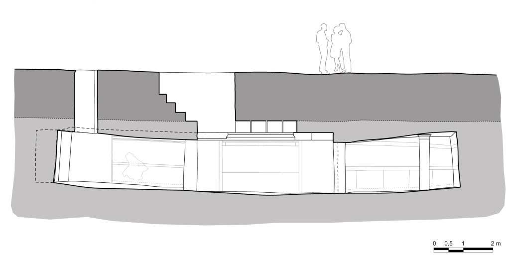

44 The Tomb of the Pillar

45 Depth 1.26 m
46 Depth 1.61m
47 Depth 1.75m
48 Depth 2.20m
49 Depth 2.45m Apparent thickness of the tomb 49 cm, real thickness 2.1 m

50 The area of the cryptoporticus in Egnazia 30 m 0 m Depth 40 cm

51 30 m 0 m Depth 94 cm

52 30 m 0 m Depth 150 cm
53 The church of Santa Croce in Gravina in Puglia Area 3 Area 1 Area m

54 Depth 22 cm

55 Depth 77 cm
56 Depth 158 cm

57 The Archaic Ditch of Manduria Pulsed GPR Prototype Depth 360 cm
58 Reconfigurable integration times f n T int n Reconfigurable radiated power at each frequency

59 The reconfiguration of the integration times as strategy again interferences in-phase components Interferences in-quadrature components samples
60 Variance of the samples = = N Q Q Q N Q Q Q N I I I N I I I N N Q N N I σ σ

61 An experiment
62 Interference of the transceivers

63 Signal with the default integration times
64 Signal with the reconfigured integration times

65 An experiment in the field


66 Interference of the repeater
67 Signal with the default integration times
68 Signal with the reconfigured integration times Increasing of the comprehensive measurement time less than 5% in both cases.
ENSC327 Communications Systems 2: Fourier Representations. Jie Liang School of Engineering Science Simon Fraser University
 ENSC327 Communications Systems 2: Fourier Representations Jie Liang School of Engineering Science Simon Fraser University 1 Outline Chap 2.1 2.5: Signal Classifications Fourier Transform Dirac Delta Function
ESS Dirac Comb and Flavors of Fourier Transforms
 6. Dirac Comb and Flavors of Fourier ransforms Consider a periodic function that comprises pulses of amplitude A and duration τ spaced a time apart. We can define it over one period as y(t) = A, τ / 2
Direct-Sequence Spread-Spectrum
 Chapter 3 Direct-Sequence Spread-Spectrum In this chapter we consider direct-sequence spread-spectrum systems. Unlike frequency-hopping, a direct-sequence signal occupies the entire bandwidth continuously.
Square Root Raised Cosine Filter
 Wireless Information Transmission System Lab. Square Root Raised Cosine Filter Institute of Communications Engineering National Sun Yat-sen University Introduction We consider the problem of signal design
7 The Waveform Channel
 7 The Waveform Channel The waveform transmitted by the digital demodulator will be corrupted by the channel before it reaches the digital demodulator in the receiver. One important part of the channel
ω 0 = 2π/T 0 is called the fundamental angular frequency and ω 2 = 2ω 0 is called the
 he ime-frequency Concept []. Review of Fourier Series Consider the following set of time functions {3A sin t, A sin t}. We can represent these functions in different ways by plotting the amplitude versus
Solutions to Problems in Chapter 4
 Solutions to Problems in Chapter 4 Problems with Solutions Problem 4. Fourier Series of the Output Voltage of an Ideal Full-Wave Diode Bridge Rectifier he nonlinear circuit in Figure 4. is a full-wave
ENSC327 Communications Systems 2: Fourier Representations. School of Engineering Science Simon Fraser University
 ENSC37 Communications Systems : Fourier Representations School o Engineering Science Simon Fraser University Outline Chap..5: Signal Classiications Fourier Transorm Dirac Delta Function Unit Impulse Fourier
Digital Band-pass Modulation PROF. MICHAEL TSAI 2011/11/10
 Digital Band-pass Modulation PROF. MICHAEL TSAI 211/11/1 Band-pass Signal Representation a t g t General form: 2πf c t + φ t g t = a t cos 2πf c t + φ t Envelope Phase Envelope is always non-negative,
FBMC/OQAM transceivers for 5G mobile communication systems. François Rottenberg
 FBMC/OQAM transceivers for 5G mobile communication systems François Rottenberg Modulation Wikipedia definition: Process of varying one or more properties of a periodic waveform, called the carrier signal,
Summary: ISI. No ISI condition in time. II Nyquist theorem. Ideal low pass filter. Raised cosine filters. TX filters
 UORIAL ON DIGIAL MODULAIONS Part 7: Intersymbol interference [last modified: 200--23] Roberto Garello, Politecnico di orino Free download at: www.tlc.polito.it/garello (personal use only) Part 7: Intersymbol
Chapter 4 The Fourier Series and Fourier Transform
 Chapter 4 The Fourier Series and Fourier Transform Representation of Signals in Terms of Frequency Components Consider the CT signal defined by N xt () = Acos( ω t+ θ ), t k = 1 k k k The frequencies `present
EE401: Advanced Communication Theory
 EE401: Advanced Communication Theory Professor A. Manikas Chair of Communications and Array Processing Imperial College London Introductory Concepts Prof. A. Manikas (Imperial College) EE.401: Introductory
Performance of Coherent Binary Phase-Shift Keying (BPSK) with Costas-Loop Tracking in the Presence of Interference
 with Costas-Loop Tracking in the Presence of Interference") TMO Progress Report 4-139 November 15, 1999 Performance of Coherent Binary Phase-Shift Keying (BPSK) with Costas-Loop Tracking in the Presence of Interference M. K. Simon 1 The bit-error probability performance
TMO Progress Report 4-139 November 15, 1999 Performance of Coherent Binary Phase-Shift Keying (BPSK) with Costas-Loop Tracking in the Presence of Interference M. K. Simon 1 The bit-error probability performance
I. Signals & Sinusoids
 I. Signals & Sinusoids [p. 3] Signal definition Sinusoidal signal Plotting a sinusoid [p. 12] Signal operations Time shifting Time scaling Time reversal Combining time shifting & scaling [p. 17] Trigonometric
ESS Finite Impulse Response Filters and the Z-transform
 9. Finite Impulse Response Filters and the Z-transform We are going to have two lectures on filters you can find much more material in Bob Crosson s notes. In the first lecture we will focus on some of
Sound & Vibration Magazine March, Fundamentals of the Discrete Fourier Transform
 Fundamentals of the Discrete Fourier Transform Mark H. Richardson Hewlett Packard Corporation Santa Clara, California The Fourier transform is a mathematical procedure that was discovered by a French mathematician
ELEG 3124 SYSTEMS AND SIGNALS Ch. 5 Fourier Transform
 Department of Electrical Engineering University of Arkansas ELEG 3124 SYSTEMS AND SIGNALS Ch. 5 Fourier Transform Dr. Jingxian Wu wuj@uark.edu OUTLINE 2 Introduction Fourier Transform Properties of Fourier
EE194-EE290C. 28 nm SoC for IoT. Acknowledgement: Wayne Stark EE455 Lecture Notes, University of Michigan
 EE194-EE290C 28 nm SoC for IoT Acknowledgement: Wayne Stark EE455 Lecture Notes, University of Michigan Noise Unwanted electric signals come from a variety of sources, both from - Naturally occurring noise
EE303: Communication Systems
 EE303: Communication Systems Professor A. Manikas Chair of Communications and Array Processing Imperial College London Introductory Concepts Prof. A. Manikas (Imperial College) EE303: Introductory Concepts
LOPE3202: Communication Systems 10/18/2017 2
 By Lecturer Ahmed Wael Academic Year 2017-2018 LOPE3202: Communication Systems 10/18/2017 We need tools to build any communication system. Mathematics is our premium tool to do work with signals and systems.
Representing a Signal
 The Fourier Series Representing a Signal The convolution method for finding the response of a system to an excitation takes advantage of the linearity and timeinvariance of the system and represents the
Signal Design for Band-Limited Channels
 Wireless Information Transmission System Lab. Signal Design for Band-Limited Channels Institute of Communications Engineering National Sun Yat-sen University Introduction We consider the problem of signal
Time and Spatial Series and Transforms
 Time and Spatial Series and Transforms Z- and Fourier transforms Gibbs' phenomenon Transforms and linear algebra Wavelet transforms Reading: Sheriff and Geldart, Chapter 15 Z-Transform Consider a digitized
Principles of Communications Lecture 8: Baseband Communication Systems. Chih-Wei Liu 劉志尉 National Chiao Tung University
 Principles of Communications Lecture 8: Baseband Communication Systems Chih-Wei Liu 劉志尉 National Chiao Tung University cwliu@twins.ee.nctu.edu.tw Outlines Introduction Line codes Effects of filtering Pulse
Mobile Radio Communications
 Course 3: Radio wave propagation Session 3, page 1 Propagation mechanisms free space propagation reflection diffraction scattering LARGE SCALE: average attenuation SMALL SCALE: short-term variations in
ELEN E4810: Digital Signal Processing Topic 11: Continuous Signals. 1. Sampling and Reconstruction 2. Quantization
 ELEN E4810: Digital Signal Processing Topic 11: Continuous Signals 1. Sampling and Reconstruction 2. Quantization 1 1. Sampling & Reconstruction DSP must interact with an analog world: A to D D to A x(t)
Fourier transform representation of CT aperiodic signals Section 4.1
 Fourier transform representation of CT aperiodic signals Section 4. A large class of aperiodic CT signals can be represented by the CT Fourier transform (CTFT). The (CT) Fourier transform (or spectrum)
Communication Theory Summary of Important Definitions and Results
 Signal and system theory Convolution of signals x(t) h(t) = y(t): Fourier Transform: Communication Theory Summary of Important Definitions and Results X(ω) = X(ω) = y(t) = X(ω) = j x(t) e jωt dt, 0 Properties
This examination consists of 11 pages. Please check that you have a complete copy. Time: 2.5 hrs INSTRUCTIONS
 THE UNIVERSITY OF BRITISH COLUMBIA Department of Electrical and Computer Engineering EECE 564 Detection and Estimation of Signals in Noise Final Examination 6 December 2006 This examination consists of
Digital Communications
 Digital Communications Chapter 5 Carrier and Symbol Synchronization Po-Ning Chen, Professor Institute of Communications Engineering National Chiao-Tung University, Taiwan Digital Communications Ver 218.7.26
ECE6604 PERSONAL & MOBILE COMMUNICATIONS. Week 3. Flat Fading Channels Envelope Distribution Autocorrelation of a Random Process
 1 ECE6604 PERSONAL & MOBILE COMMUNICATIONS Week 3 Flat Fading Channels Envelope Distribution Autocorrelation of a Random Process 2 Multipath-Fading Mechanism local scatterers mobile subscriber base station
that efficiently utilizes the total available channel bandwidth W.
 Signal Design for Band-Limited Channels Wireless Information Transmission System Lab. Institute of Communications Engineering g National Sun Yat-sen University Introduction We consider the problem of signal
LECTURE 12 Sections Introduction to the Fourier series of periodic signals
 Signals and Systems I Wednesday, February 11, 29 LECURE 12 Sections 3.1-3.3 Introduction to the Fourier series of periodic signals Chapter 3: Fourier Series of periodic signals 3. Introduction 3.1 Historical
Fourier Series and Transform KEEE343 Communication Theory Lecture #7, March 24, Prof. Young-Chai Ko
 Fourier Series and Transform KEEE343 Communication Theory Lecture #7, March 24, 20 Prof. Young-Chai Ko koyc@korea.ac.kr Summary Fourier transform Properties Fourier transform of special function Fourier
ECG782: Multidimensional Digital Signal Processing
 Professor Brendan Morris, SEB 3216, brendan.morris@unlv.edu ECG782: Multidimensional Digital Signal Processing Spring 2014 TTh 14:30-15:45 CBC C313 Lecture 05 Image Processing Basics 13/02/04 http://www.ee.unlv.edu/~b1morris/ecg782/
Radar Systems Engineering Lecture 3 Review of Signals, Systems and Digital Signal Processing
 Radar Systems Engineering Lecture Review of Signals, Systems and Digital Signal Processing Dr. Robert M. O Donnell Guest Lecturer Radar Systems Course Review Signals, Systems & DSP // Block Diagram of
8 PAM BER/SER Monte Carlo Simulation
 xercise.1 8 PAM BR/SR Monte Carlo Simulation - Simulate a 8 level PAM communication system and calculate bit and symbol error ratios (BR/SR). - Plot the calculated and simulated SR and BR curves. - Plot
Digital Baseband Systems. Reference: Digital Communications John G. Proakis
 Digital Baseband Systems Reference: Digital Communications John G. Proais Baseband Pulse Transmission Baseband digital signals - signals whose spectrum extend down to or near zero frequency. Model of the
Fourier Transform. Find the Fourier series for a periodic waveform Determine the output of a filter when the input is a periodic function
 Objectives: Be able to Fourier Transform Find the Fourier series for a periodic waveform Determine the output of a filter when the input is a periodic function Filters with a Single Sinusoidal Input: Suppose
Correlation, discrete Fourier transforms and the power spectral density
 Correlation, discrete Fourier transforms and the power spectral density visuals to accompany lectures, notes and m-files by Tak Igusa tigusa@jhu.edu Department of Civil Engineering Johns Hopkins University
A Family of Nyquist Filters Based on Generalized Raised-Cosine Spectra
 Proc. Biennial Symp. Commun. (Kingston, Ont.), pp. 3-35, June 99 A Family of Nyquist Filters Based on Generalized Raised-Cosine Spectra Nader Sheikholeslami Peter Kabal Department of Electrical Engineering
Chapter 4 The Fourier Series and Fourier Transform
 Chapter 4 The Fourier Series and Fourier Transform Fourier Series Representation of Periodic Signals Let x(t) be a CT periodic signal with period T, i.e., xt ( + T) = xt ( ), t R Example: the rectangular
GATE EE Topic wise Questions SIGNALS & SYSTEMS
 www.gatehelp.com GATE EE Topic wise Questions YEAR 010 ONE MARK Question. 1 For the system /( s + 1), the approximate time taken for a step response to reach 98% of the final value is (A) 1 s (B) s (C)
TLT-5200/5206 COMMUNICATION THEORY, Exercise 1, Fall 2012
 Problem 1. a) Derivation By definition, we can write the inverse Fourier transform of the derivative of x(t) as d d jπ X( f ) { e } df d jπ x() t X( f ) e df jπ j π fx( f ) e df Again, by definition of
III. Spherical Waves and Radiation
 III. Spherical Waves and Radiation Antennas radiate spherical waves into free space Receiving antennas, reciprocity, path gain and path loss Noise as a limit to reception Ray model for antennas above a
2.1 Introduction 2.22 The Fourier Transform 2.3 Properties of The Fourier Transform 2.4 The Inverse Relationship between Time and Frequency 2.
 Chapter2 Fourier Theory and Communication Signals Wireless Information Transmission System Lab. Institute of Communications Engineering g National Sun Yat-sen University Contents 2.1 Introduction 2.22
Gabor Deconvolution. Gary Margrave and Michael Lamoureux
 Gabor Deconvolution Gary Margrave and Michael Lamoureux = Outline The Gabor idea The continuous Gabor transform The discrete Gabor transform A nonstationary trace model Gabor deconvolution Examples = Gabor
Chapter 5 Frequency Domain Analysis of Systems
 Chapter 5 Frequency Domain Analysis of Systems CT, LTI Systems Consider the following CT LTI system: xt () ht () yt () Assumption: the impulse response h(t) is absolutely integrable, i.e., ht ( ) dt< (this
HARMONIC WAVELET TRANSFORM SIGNAL DECOMPOSITION AND MODIFIED GROUP DELAY FOR IMPROVED WIGNER- VILLE DISTRIBUTION
 HARMONIC WAVELET TRANSFORM SIGNAL DECOMPOSITION AND MODIFIED GROUP DELAY FOR IMPROVED WIGNER- VILLE DISTRIBUTION IEEE 004. All rights reserved. This paper was published in Proceedings of International
Timbral, Scale, Pitch modifications
 Introduction Timbral, Scale, Pitch modifications M2 Mathématiques / Vision / Apprentissage Audio signal analysis, indexing and transformation Page 1 / 40 Page 2 / 40 Modification of playback speed Modifications
1 otherwise. Note that the area of the pulse is one. The Dirac delta function (a.k.a. the impulse) can be defined using the pulse as follows:
 can be defined using the pulse as follows:") The Dirac delta function There is a function called the pulse: { if t > Π(t) = 2 otherwise. Note that the area of the pulse is one. The Dirac delta function (a.k.a. the impulse) can be defined using the
The Dirac delta function There is a function called the pulse: { if t > Π(t) = 2 otherwise. Note that the area of the pulse is one. The Dirac delta function (a.k.a. the impulse) can be defined using the
EE 435. Lecture 32. Spectral Performance Windowing
 EE 435 Lecture 32 Spectral Performance Windowing . Review from last lecture. Distortion Analysis T 0 T S THEOREM?: If N P is an integer and x(t) is band limited to f MAX, then 2 Am Χ mnp 1 0 m h N and
EE 230 Lecture 40. Data Converters. Amplitude Quantization. Quantization Noise
 EE 230 Lecture 40 Data Converters Amplitude Quantization Quantization Noise Review from Last Time: Time Quantization Typical ADC Environment Review from Last Time: Time Quantization Analog Signal Reconstruction
Chapter 2: The Fourier Transform
 EEE, EEE Part A : Digital Signal Processing Chapter Chapter : he Fourier ransform he Fourier ransform. Introduction he sampled Fourier transform of a periodic, discrete-time signal is nown as the discrete
ECS332: Midterm Examination (Set I) Seat
 Seat") Sirindhorn International Institute of Technology Thammasat University at Rangsit School of Information, Computer and Communication Technology ECS33: Midterm Examination (Set I) COURSE : ECS33 (Principles
Sirindhorn International Institute of Technology Thammasat University at Rangsit School of Information, Computer and Communication Technology ECS33: Midterm Examination (Set I) COURSE : ECS33 (Principles
PCM Reference Chapter 12.1, Communication Systems, Carlson. PCM.1
 PCM Reference Chapter 1.1, Communication Systems, Carlson. PCM.1 Pulse-code modulation (PCM) Pulse modulations use discrete time samples of analog signals the transmission is composed of analog information
Unitary Design of Radar Waveform Diversity Sets
 Unitary Design of Radar Waveform Diversity Sets Michael D. Zoltowski, ariq R. Qureshi, Robert Calderbank, and William Moran Abstract In this work, multiple radar waveforms are simultaneously transmitted,
4.1. If the input of the system consists of the superposition of M functions, M
 4. The Zero-State Response: The system state refers to all information required at a point in time in order that a unique solution for the future output can be compute from the input. In the case of LTIC
Q. 1 Q. 25 carry one mark each.
 GATE 5 SET- ELECTRONICS AND COMMUNICATION ENGINEERING - EC Q. Q. 5 carry one mark each. Q. The bilateral Laplace transform of a function is if a t b f() t = otherwise (A) a b s (B) s e ( a b) s (C) e as
A First Course in Digital Communications
 A First Course in Digital Communications Ha H. Nguyen and E. Shwedyk February 9 A First Course in Digital Communications 1/46 Introduction There are benefits to be gained when M-ary (M = 4 signaling methods
Chapter 5 Frequency Domain Analysis of Systems
 Chapter 5 Frequency Domain Analysis of Systems CT, LTI Systems Consider the following CT LTI system: xt () ht () yt () Assumption: the impulse response h(t) is absolutely integrable, i.e., ht ( ) dt< (this
Topic 3: Fourier Series (FS)
") ELEC264: Signals And Systems Topic 3: Fourier Series (FS) o o o o Introduction to frequency analysis of signals CT FS Fourier series of CT periodic signals Signal Symmetry and CT Fourier Series Properties
ELEC264: Signals And Systems Topic 3: Fourier Series (FS) o o o o Introduction to frequency analysis of signals CT FS Fourier series of CT periodic signals Signal Symmetry and CT Fourier Series Properties
E2.5 Signals & Linear Systems. Tutorial Sheet 1 Introduction to Signals & Systems (Lectures 1 & 2)
") E.5 Signals & Linear Systems Tutorial Sheet 1 Introduction to Signals & Systems (Lectures 1 & ) 1. Sketch each of the following continuous-time signals, specify if the signal is periodic/non-periodic,
E.5 Signals & Linear Systems Tutorial Sheet 1 Introduction to Signals & Systems (Lectures 1 & ) 1. Sketch each of the following continuous-time signals, specify if the signal is periodic/non-periodic,
SEISMIC WAVE PROPAGATION. Lecture 2: Fourier Analysis
 SEISMIC WAVE PROPAGATION Lecture 2: Fourier Analysis Fourier Series & Fourier Transforms Fourier Series Review of trigonometric identities Analysing the square wave Fourier Transform Transforms of some
EE5713 : Advanced Digital Communications
 EE5713 : Advanced Digital Communications Week 12, 13: Inter Symbol Interference (ISI) Nyquist Criteria for ISI Pulse Shaping and Raised-Cosine Filter Eye Pattern Equalization (On Board) 20-May-15 Muhammad
Communication Systems Lecture 21, 22. Dong In Kim School of Information & Comm. Eng. Sungkyunkwan University
 Communication Systems Lecture 1, Dong In Kim School of Information & Comm. Eng. Sungkyunkwan University 1 Outline Linear Systems with WSS Inputs Noise White noise, Gaussian noise, White Gaussian noise
2.1 Basic Concepts Basic operations on signals Classication of signals
 Haberle³me Sistemlerine Giri³ (ELE 361) 9 Eylül 2017 TOBB Ekonomi ve Teknoloji Üniversitesi, Güz 2017-18 Dr. A. Melda Yüksel Turgut & Tolga Girici Lecture Notes Chapter 2 Signals and Linear Systems 2.1
2.161 Signal Processing: Continuous and Discrete
 MI OpenCourseWare http://ocw.mit.edu.6 Signal Processing: Continuous and Discrete Fall 8 For information about citing these materials or our erms of Use, visit: http://ocw.mit.edu/terms. MASSACHUSES INSIUE
Signals and Systems: Part 2
 Signals and Systems: Part 2 The Fourier transform in 2πf Some important Fourier transforms Some important Fourier transform theorems Convolution and Modulation Ideal filters Fourier transform definitions
Laplace Transform Part 1: Introduction (I&N Chap 13)
") Laplace Transform Part 1: Introduction (I&N Chap 13) Definition of the L.T. L.T. of Singularity Functions L.T. Pairs Properties of the L.T. Inverse L.T. Convolution IVT(initial value theorem) & FVT (final
Laplace Transform Part 1: Introduction (I&N Chap 13) Definition of the L.T. L.T. of Singularity Functions L.T. Pairs Properties of the L.T. Inverse L.T. Convolution IVT(initial value theorem) & FVT (final
Stochastic Processes. M. Sami Fadali Professor of Electrical Engineering University of Nevada, Reno
 Stochastic Processes M. Sami Fadali Professor of Electrical Engineering University of Nevada, Reno 1 Outline Stochastic (random) processes. Autocorrelation. Crosscorrelation. Spectral density function.
Part 7. Nonlinearity
 Part 7 Nonlinearity Linear System Superposition, Convolution re ( ) re ( ) = r 1 1 = r re ( 1 + e) = r1 + r e excitation r = r() e response In the time domain: t rt () = et () ht () = e( τ) ht ( τ) dτ
System Identification & Parameter Estimation
 System Identification & Parameter Estimation Wb3: SIPE lecture Correlation functions in time & frequency domain Alfred C. Schouten, Dept. of Biomechanical Engineering (BMechE), Fac. 3mE // Delft University
Filter Banks II. Prof. Dr.-Ing. G. Schuller. Fraunhofer IDMT & Ilmenau University of Technology Ilmenau, Germany
 Filter Banks II Prof. Dr.-Ing. G. Schuller Fraunhofer IDMT & Ilmenau University of Technology Ilmenau, Germany Page Modulated Filter Banks Extending the DCT The DCT IV transform can be seen as modulated
EE456 Digital Communications
 EE456 Digital Communications Professor Ha Nguyen September 5 EE456 Digital Communications Block Diagram of Binary Communication Systems m ( t { b k } b k = s( t b = s ( t k m ˆ ( t { bˆ } k r( t Bits in
The Hilbert Transform
 The Hilbert Transform David Hilbert 1 ABSTRACT: In this presentation, the basic theoretical background of the Hilbert Transform is introduced. Using this transform, normal real-valued time domain functions
EA2.3 - Electronics 2 1
 In the previous lecture, I talked about the idea of complex frequency s, where s = σ + jω. Using such concept of complex frequency allows us to analyse signals and systems with better generality. In this
ECG782: Multidimensional Digital Signal Processing
 Professor Brendan Morris, SEB 3216, brendan.morris@unlv.edu ECG782: Multidimensional Digital Signal Processing Filtering in the Frequency Domain http://www.ee.unlv.edu/~b1morris/ecg782/ 2 Outline Background
DCSP-2: Fourier Transform
 DCSP-2: Fourier Transform Jianfeng Feng Department of Computer Science Warwick Univ., UK Jianfeng.feng@warwick.ac.uk http://www.dcs.warwick.ac.uk/~feng/dcsp.html Data transmission Channel characteristics,
EE4512 Analog and Digital Communications Chapter 4. Chapter 4 Receiver Design
 Chapter 4 Receiver Design Chapter 4 Receiver Design Probability of Bit Error Pages 124-149 149 Probability of Bit Error The low pass filtered and sampled PAM signal results in an expression for the probability
Frequency Response and Continuous-time Fourier Series
 Frequency Response and Continuous-time Fourier Series Recall course objectives Main Course Objective: Fundamentals of systems/signals interaction (we d like to understand how systems transform or affect
Summary II: Modulation and Demodulation
 Summary II: Modulation and Demodulation Instructor : Jun Chen Department of Electrical and Computer Engineering, McMaster University Room: ITB A1, ext. 0163 Email: junchen@mail.ece.mcmaster.ca Website:
Reciprocal Mixing: The trouble with oscillators
 Reciprocal Mixing: The trouble with oscillators Tradeoffs in RX Noise Figure(Sensitivity) Distortion (Linearity) Phase Noise (Aliasing) James Buckwalter Phase Noise Phase noise is the frequency domain
Virtual Array Processing for Active Radar and Sonar Sensing
 SCHARF AND PEZESHKI: VIRTUAL ARRAY PROCESSING FOR ACTIVE SENSING Virtual Array Processing for Active Radar and Sonar Sensing Louis L. Scharf and Ali Pezeshki Abstract In this paper, we describe how an
3F1 Random Processes Examples Paper (for all 6 lectures)
") 3F Random Processes Examples Paper (for all 6 lectures). Three factories make the same electrical component. Factory A supplies half of the total number of components to the central depot, while factories
3F Random Processes Examples Paper (for all 6 lectures). Three factories make the same electrical component. Factory A supplies half of the total number of components to the central depot, while factories
MATHEMATICAL TOOLS FOR DIGITAL TRANSMISSION ANALYSIS
 ch03.qxd 1/9/03 09:14 AM Page 35 CHAPTER 3 MATHEMATICAL TOOLS FOR DIGITAL TRANSMISSION ANALYSIS 3.1 INTRODUCTION The study of digital wireless transmission is in large measure the study of (a) the conversion
A6523 Signal Modeling, Statistical Inference and Data Mining in Astrophysics Spring 2013
 A6523 Signal Modeling, Statistical Inference and Data Mining in Astrophysics Spring 2013 Lecture 26 Localization/Matched Filtering (continued) Prewhitening Lectures next week: Reading Bases, principal
Correlator I. Basics. Chapter Introduction. 8.2 Digitization Sampling. D. Anish Roshi
 Chapter 8 Correlator I. Basics D. Anish Roshi 8.1 Introduction A radio interferometer measures the mutual coherence function of the electric field due to a given source brightness distribution in the sky.
Parameter Estimation
 1 / 44 Parameter Estimation Saravanan Vijayakumaran sarva@ee.iitb.ac.in Department of Electrical Engineering Indian Institute of Technology Bombay October 25, 2012 Motivation System Model used to Derive
be the set of complex valued 2π-periodic functions f on R such that
 . Fourier series. Definition.. Given a real number P, we say a complex valued function f on R is P -periodic if f(x + P ) f(x) for all x R. We let be the set of complex valued -periodic functions f on
Basics about Fourier analysis
 Jérôme Gilles UCLA PART ONE Fourier analysis On the menu... Introduction - some history... Notations. Fourier series. Continuous Fourier transform. Discrete Fourier transform. Properties. 2D extension.
Figure 3.1 Effect on frequency spectrum of increasing period T 0. Consider the amplitude spectrum of a periodic waveform as shown in Figure 3.2.
 3. Fourier ransorm From Fourier Series to Fourier ransorm [, 2] In communication systems, we oten deal with non-periodic signals. An extension o the time-requency relationship to a non-periodic signal
Introduction to time-frequency analysis. From linear to energy-based representations
 Introduction to time-frequency analysis. From linear to energy-based representations Rosario Ceravolo Politecnico di Torino Dep. Structural Engineering UNIVERSITA DI TRENTO Course on «Identification and
Functions not limited in time
 Functions not limited in time We can segment an arbitrary L 2 function into segments of width T. The mth segment is u m (t) = u(t)rect(t/t m). We then have m 0 u(t) =l.i.m. m0 u m (t) m= m 0 This wors
Detection and Estimation Theory
 ESE 54 Detection and Estimation heory Joseph A. O Sullivan Samuel C. Sachs Professor Electronic Systems and Signals Research Laboratory Electrical and Systems Engineering Washington University Urbauer
EE 435. Lecture 30. Data Converters. Spectral Performance
 EE 435 Lecture 30 Data Converters Spectral Performance . Review from last lecture. INL Often Not a Good Measure of Linearity Four identical INL with dramatically different linearity X OUT X OUT X REF X
This examination consists of 10 pages. Please check that you have a complete copy. Time: 2.5 hrs INSTRUCTIONS
 THE UNIVERSITY OF BRITISH COLUMBIA Department of Electrical and Computer Engineering EECE 564 Detection and Estimation of Signals in Noise Final Examination 08 December 2009 This examination consists of
DESIGN OF CMOS ANALOG INTEGRATED CIRCUITS
 DESIGN OF CMOS ANALOG INEGRAED CIRCUIS Franco Maloberti Integrated Microsistems Laboratory University of Pavia Discrete ime Signal Processing F. Maloberti: Design of CMOS Analog Integrated Circuits Discrete
8.1 Circuit Parameters
 8.1 Circuit Parameters definition of decibels using decibels transfer functions impulse response rise time analysis Gaussian amplifier transfer function RC circuit transfer function analog-to-digital conversion