CEMAC - CE-marking of cables
|
|
|
- Melvyn Blake Morris
- 5 years ago
- Views:
Transcription


1 CEMAC - CE-marking of cables Terence Journeaux Björn Sundström Patrik Johansson Michael Försth Stephen J Grayson Sean Gregory Hervé Breulet Silvio Messa Reiner Lehrer Marc Kobilsek Hans-Detlef Leppert Neil Mabbott Europacable SP Technical Research Institute of Sweden SP Technical Research Institute of Sweden SP Technical Research Institute of Sweden Interscience Communications, UK Interscience Communications, UK ISSEP, Belgium LSF, Italy VDE, Germany Europacable Europacable Europacable Fire Technology SP Report
2 2 Abstract CEMAC, CE MArking of Cables, is a project with the objective of supporting a smooth transfer from national reaction to fire requirements in Europe to harmonised CE-marking requirements. The starting point is the European Commission decision on classification criteria from 26 and the test procedures referenced by the decision. The CEMAC project has improved the testing standards, developed procedures for Extended Application of Test Results, EXAP, and contributed with a large test data base. CEMAC is a co-operation between a group of research institutes, testing laboratories and industry, Europacable. It is believed that the results will be used in the European system shortly. Key words: Burning behaviour of cables, Fire Growth Rate of cables, fire testing, CE-marking, reaction to fire of cables, extended application of test results on cables, FIPEC, pren 5399, EN , EN , EN SP Sveriges Tekniska Forskningsinstitut SP Technical Research Institute of Sweden SP Report ISBN ISSN Borås 21
3 3 Contents 1 Background to the CEMAC project 6 2 Executive summary and conclusions 9 3 Cable selection and procurement 11 4 Experimental program and laboratory qualification through round robin Qualifying programme of work Data base cable tests 18 5 Data management Introduction Data bank Contents of the data bank Organisation and handling of data base Availability of the data Data formats, storing and exchanging Internal laboratory formats Data stored in the data bank Data stored at the laboratories Analysis Exchanging data Codes for identification of CEMAC tests in the data bank 21 6 Large scale tests results Test method Measurements and derived parameters Number of tests Test results Group Group 3st Group 3lt Group 3ct Group 3tb Group Group Group Group 8a Group 8b Group Group Group Group Group Spread of results all groups Selection of typical results 36 7 Extended application, EXAP Safety margin Cables with singular behaviour Cables larger than the tested range Generic rules for cables not included in CEMAC 52
4 4 7.5 Flaming droplets/particles EXAP for Data cables CWFT Extrapolation rule EXAP for Optical cables EXAP for EN EXAP for EN EXAP flow chart 63 8 Test results EN and EN Analysis of EN results from Europacable laboratories Spread of results by Group Spread of results by Class Conclusions Analysis of pren 5399 smoke results versus EN tests results obtained by Europacable laboratories Smoke classification analysis Discriminant parameter for s classification according to pren Correlation between pren 5399 and EN EXAP cable parameter and EN measurement Conclusions 68 References 69 9 Annex A, Cable details and photographs 7 1 Annex B, Test results EN and EN Annex C, Analysis of results Peak HRR THR FIGRA Flame spread Peak SPR TSP Annex D, Proposal for EXAP rules for power cables Definition of a product family for EXAP for power cables EXAP with safety margin Cables larger than the tested range Generic rules Flaming droplets/particles Annex E, Summary graphs of cable group test results and table of main scalar values, RTD Annex F, pren 5399 raw data format 162
5 5 Abbreviations d [m] Outer diameter. N [] Number of cables on the ladder, or, when applicable, number of bundles on the ladder. V combust [m 2 ] Non-metallic volume per meter ladder. v combust [m 2 ] Non-metallic volume per meter cable. ν class different Value for classification in EXAP. ν max different Maximum measured value in EXAP. ν sm different Safety margin to be used in EXAP. c [] Number of conductors in one cable. Acknowledgements CEMAC, CE MArking of Cables, is a project financed by Europacable. CEMAC was performed in close cooperation between a group of research laboratories, the RTD-group, and a group of Europacable companies. The RTD group consisted of SP, Interscience, ISSEP, LSF and VDE. The project was lead by Europacable and the RTD contributions were led by SP. The project was financed by Europacable and the expertise and testing work of the Europacable laboratories were invaluable for the project results. The involved Europacable laboratories were Acome, Draka DE, General Cable, Prysmian UK, Draka NL, Nexans DE, Nexans FR and NKT. Finally the joint competence and work of the researchers and the testing teams of the RTD laboratories was the necessary prerequisite for the project to be successful.
6 6 1 Background to the CEMAC project CE-marking according to the Construction Products Directive (CPD) requires that harmonised test standards and corresponding classification criteria are available. In the case of fire properties it is also necessary that harmonised procedures of so called extended application of test results, EXAP, are available. EXAP allows a family of products to be classified to a certain fire property without testing all of the individual members of the family. Availability of EXAP is an essential requirement for cables as the individual variation of the products is so large that the number of tests required for classification would become impossible to handle. The European Commission can take a decision on classification without further testing, CWFT (Classification Without Further Testing), provided that the appropriate technical basis is given. Smooth introduction of CE-marking for cables in the fire area requires that the technical testing standards are tried out, validated and reproducible. The EXAP procedures must be developed and available and further CWFT decisions from the Commission may be required. The CEMAC project provides the technical data and EXAP procedures that would simplify CEmarking of the reaction to fire properties of cables in Europe. The standard pren 5399 is the major test procedure for reaction to fire of cables, see section 6.1. This test specification derives from work done in a large project funded by the EU called FIPEC, Fire Performance of Electric Cables [1]. The FIPEC project was performed by a research group consisting of SP, Interscience, ISSEP and CESI. The FIPEC project included a study of cable installations and relevant reference scenarios as well as a comprehensive test program of different kinds of cables. This together with some additional test data was used in the development of the proposal for the European testing and classification system. The proposal of reaction to fire classes was developed in co-operation with European regulators and the cable industry in Europe and presented in 23 [2], [3]. The European Commission decided on a testing and classification system on cables during 26 [4], see Table 1. The system is built in the same way as that used for linings and pipe insulation. However, it also included the possibility to declare acidity of the smoke gases, the sub-classes a1, a2 and a3.
7 7 Table 1. Classes of reaction to fire performance for cables [4]. Class Test method(s) Classification criteria Additional classification Aca EN ISO 1716 PCS 2, MJ/kg (1) B1ca FIPEC2 Scen 2 ( 5 ) And EN B2ca FIPEC2 Scen 1 ( 5 ) and FS 1.75 m and THR12s 1 MJ and Peak HRR 2 kw and FIGRA 12 Ws -1 H 425 mm FS 1.5 m; and THR12s 15 MJ; and Peak HRR 3 kw; and FIGRA 15 Ws -1 Smoke production ( 2, 6 ) and Flaming droplets/particles ( 3 ) and Acidity ( 4, 8 ) Smoke production ( 2, 7 ) and Flaming droplets/particles ( 3 ) and Acidity ( 4, 8 ) EN H 425 mm Cca FIPEC2 Scen 1 ( 5 ) FS 2. m; and THR12s 3 MJ; and Smoke production ( 2, 7 ) and Flaming droplets/particles ( 3 ) and Acidity ( 4, 8 ) And Peak HRR 6 kw; and FIGRA 3 Ws -1 EN H 425 mm Dca FIPEC2 Scen 1 ( 5 ) THR12s 7 MJ; and Peak HRR 4 kw; and Smoke production ( 2, 7 ) and Flaming droplets/particles ( 3 ) and Acidity ( 4, 8 ) And FIGRA 13 Ws -1 EN H 425 mm Eca EN H 425 mm Fca No performance determined ( 1 ) For the product as a whole, excluding metallic materials, and for any external component (i.e. sheath) of the product. ( 2 ) s1 = TSP12 5 m 2 and Peak SPR.25 m 2 /s s1a = s1 and transmittance in accordance with EN % s1b = s1 and transmittance in accordance with EN % < 8% s2 = TSP12 4 m 2 and Peak SPR 1.5 m 2 /s s3 = not s1 or s2 ( 3 ) For FIPEC2 Scenarios 1 and 2: d = No flaming droplets/particles within 12 s; d1 = No flaming droplets/ particles persisting longer than 1 s within 12 s; d2 = not d or d1. ( 4 ) EN : a1 = conductivity < 2.5 µs/mm and ph > 4,3; a2 = conductivity < 1 µs/mm and ph > 4.3; a3 = not a1 or a2. No declaration = No Performance Determined. ( 5 ) Air flow into chamber shall be set to 8 ± 8 l/min. FIPEC2 Scenario 1 = pren with mounting and fixing as below FIPEC2 Scenario 2 = pren with mounting and fixing as below ( 6 ) The smoke class declared for class B1ca cables must originate from the FIPEC2 Scen 2 test. ( 7 ) The smoke class declared for class B2ca, Cca, Dca cables must originate from the FIPEC2 Scen 1 test. ( 8 ) Measuring the hazardous properties of gases developed in the event of fire, which compromise the ability of the persons exposed to them to take effective action to accomplish escape, and not describing the toxicity of these gases.
8 8 Further work was done on the test procedure in CENELEC which has resulted in improvement of a number of technical details to pren 5399 which now is ready for final vote (December 29). Two round robin exercises have been carried out on the test [5], [6]. The first round robin was performed on behalf of Europacable with industry laboratories together with the developers of the system, the FIPEC laboratories. The second round robin was performed through CENELEC and included many test sites. The results were good and comparable to the results of the SBI test used for linings. Thus the test procedure used is quite robust and well developed. These test results were validated in the FIPEC project for real fires by using reference scenarios and through further analysis and comparisons to other building products under the CPD, see [1], [7]. With this background the CEMAC project was created to add EXAP procedures and further test data on different cables. Additional testing laboratories, LSF and VDE, and a large group of Europacable laboratories formed together with the FIPEC partners a group to undertake the CEMAC project. The project test data base includes approximately 2 large scale test results on which the EXAP analysis were performed. The work in the project was divided into the following tasks. Table 2. Responsible partner for each activity. Activity Responsible partner Project management ECBL Project management RTD group SP Cable selection ECBL Basic calibration exercise of test Interscience equipment and qualification to run tests in the project Collection of raw data and analysis of Interscience HRR, Smoke etc Tests according to pren 5399 with FIPEC scen 1 Tests according to pren 5399 with FIPEC scen 1, EN and EN Analysis and development of EXAP procedure Final report and Web-based data base SP ISSEP LSF VDE 43 tests 41 tests 21 tests 1 tests Europacable industry laboratories. pren 5399: 83 tests EN : 88 tests EN : 88 tests SP SP The authors of the various sections are as follows: Sections 3, 7.6.2, 7.8, 7.9, 8 and 1 were written by ECBL. Sections 1, 2, , 7.1, 9, 11 and 12 were written by SP. Sections 4, 5, 13, 14 and 15 were written by Interscience. Sections 6, 7.6, and 7.7 were written by ISSeP. The EXAP rules presented in this study are applicable for the test method presented in standard pren 5399 FIPEC scen 1, i.e. European Class B2 CA- Class D CA. In addition analysis is performed concerning the EN and EN for small flame ignition and smoke production (3 m cube) respectively. The EXAP rules are developed to enable classification according to the Commission decision. The calculation procedures are not developed to predict scalar or vector data for the different fire parameters. According to pren 5399 FIPEC scen 1 standard the flame should be applied for 2 minutes. The EXAP rules presented are only applicable to results from pren 5399 FIPEC scen 1 test procedure.
9 9 2 Executive summary and conclusions The CEMAC project is based on the findings of many years of research in the area of testing, modelling and classifying the burning behaviour of cables. CEMAC work has now added additional test data and analysis for predicting fire classification of cables. The underpinning technology that can be used to support CE-marking can be summarised as follows: The selection of cables for the CEMAC project was based on the cables being representative of the European market and was selected to have a wide range of burning behaviour. This means that conclusions drawn from the project are representative of real European market situations. The test procedure according to pren 5399 FIPEC scen 1 originates from the FIPEC project [1] and was further improved through the work of CENELEC TC 2 WG 1. The Round Robin which used the improved procedure showed good results comparable to the European SBI test round robin [6]. This was confirmed during the course of the CEMAC test programme. The classification criteria according to the Commission decision [4] were considered during the course of the EXAP analysis and they were found to be consistent and posed no problems in developing the EXAP-system. The calculation procedures required for the EXAP rules for cables are not obvious as the fire performance of a cable is quite complex. Thus simple rules based on simple single parameters such as the amount of combustible materials, and testing worst and best case are not possible. There will be outliers due to influences of the number of conductors, type of shield etc. A new parameter χ was developed to facilitate EXAP development. This is defined by the equation: χ = where c d V 2 combust d [m] Outer diameter. V combust [m 2 ] Non-metallic volume per meter ladder. c [] Number of conductors in one cable. This parameter was used to calculate which cables to select for test and a specific EXAP procedure was developed. In addition cable families that fall outside of the ranges of the database can also, under certain conditions, be subjected to EXAP using a statistical analysis developed in this project. The precision of the specific EXAP was calculated using the database. The result was that the risk for drawing the wrong conclusion based on the EXAP procedure is virtually zero, see Table 3 below.
10 1 Table 3. Error rate for the different classification parameters. Total number of Number of incorrect combinations classifications Percentage of incorrect classifications Peak HRR [kw] 166 THR [MJ] 166 FIGRA [Ws -1 ] % Flame spread [m] % Peak SPR [m 2 s -1 ] % TSP [m 2 ] % The error rates reported in the table are given for each individual classification parameter. As can be seen the number of incorrect classifications is very low for all parameters. It is highly unlikely that a cable would be wrongly classified in this system. In order that a cable should be erroneously classified as for example B2 ca while in reality it is C ca it would need to have been classified as B2 ca for all classification parameters: peak HRR, THR, FIGRA and Flame spread. The confidence of the EXAP procedure is therefore high. The developed EXAP procedures are not applicable to data cables and optical cables as they were outside the scope of the study. However, tests were performed on these cables and the data, although limited, was analysed. The analysis showed some promising trends for EXAP rules, but more work for a conclusion is needed. The small flame test EN was found to be not significant in this project. The entire cable population tested passed this test. EXAP can therefore be similar to the main procedure as it seems not be important how this is done. Smoke production measured according to EN , the 3 m cube, is fundamentally different from how SPR is measured in pren In EN a certain length of a cable is burning and the smoke is accumulated in a box having a volume of 27 m 3. In the pren 5399 test a cable ladder is burning and the instantaneous smoke production is measured, a so called flow through system. No correlation between the tests was expected, which was confirmed. The best agreement was found when comparing total smoke production, TSP, according to pren 5399 with EN This would be expected as two integral values are compared; smoke accumulation in the 3 m cube box with integrated smoke production rate in the flow through system. It was also found that TSP was the determining parameter for classification in almost all cases. However, all of the products passing the s1 level in pren 5399 were either s1a or s1 b according to the 3 m cube. In other words, you must meet the s1 criteria to be sure that the product will meet either s1a or s1b. This is consistent with the classification criteria, see Table 1, which are: s1a = s1 and transmittance in accordance with EN % s1b = s1 and transmittance in accordance with EN % < 8% However, since the s1 rating at least means that s1b is fulfilled, the deletion of the s1b class could be considered as it is not adding any further information. At present, no EXAP rule is proposed for smoke classification according to EN The development of such a rule is being further considered based upon the data generated in the project.
11 11 In short, the conclusions from the CEMAC study are: The testing procedures are well developed, repeatable and reproducible. The error rates from the proposed EXAP procedure appears to be virtually zero considering the available data and therefore an EXAP according to this procedure should be quite stable. The classification criteria from the commission decision seem to work well together with testing and EXAP procedures. The developed EXAP procedures are not applicable to data cables and optical cables. The small flame test may be subject to CWFT. Smoke production classification is consistent between the two tests involved in the sense that cables classified as s1a or s1b in the EN test are also classified as s1 according to pren It can be considered whether the s1b class should be deleted. 3 Cable selection and procurement Cable selection for the test program was made on the basis of achieving a selection of those generic power, data and optical fibre cable constructions (generic families) that are widely available on the European market. The cables selected to represent each generic family of power cables include a range of conductor sizes from approximately the smallest to approximately the largest commonly available. Within each generic family, specific sub families of cables containing PVC and halogen free materials were procured as both types are widely available on the market. Additionally, both copper and aluminium conductor were procured. Because of the very wide market applicability of the unarmoured multicore power cable types and the varying national standard designs for such types, specific families from more than one country were procured. The specific families of cables were also chosen to represent a wide range of burning behaviour as judged by pre-existing tests. This ranged from designs with no special reduced flame propagation performance which were expected to fall in Class D ca /E ca to those with good reduced flame propagation performance which were expected to fall in Class B2 ca/c ca. The test results achieved have demonstrated that such a range of burning behaviour was achieved. Overall, some 115 samples from 9 countries were procured from within the Europacable membership.
12 12 Within this report, the families of cables are identified by a Group number: - Generic family - single core unsheathed power cables with copper conductor Sub family - PVC Group 11 Sub family - halogen free Group 12 - Generic family - single core sheathed power cables Sub family - PVC with copper conductor Group 9 Sub family - halogen free with copper conductor Group 1 Sub family - halogen free with aluminium conductor Group 1 - Generic family - unarmoured multicore power cables with copper conductors Sub family - PVC - Group 7 Sub family - halogen free Group 8a Group 8b Different manufacturer Group 13 Different manufacturers - Generic family - armoured multicore power cables with copper conductors Sub family - PVC Group 5 Sub family - halogen free Group 6 - Generic family - screened and unscreened data cables Group 1 - Generic family - optical fibre cables Sub family - single tube Group 3 Sub family - loose tube Group 3 Sub family - corrugated tube Group 3 Sub family - tight buffer Group 3 - Generic family - telecommunication cables with copper conductors Group 2 (No cables were supplied in this Group) - Generic family - co-axial cables Group 4 (No cables were supplied in this Group)
13 13 Table 4 Group number and description Selected cables with additional data regarding mounting and EXAP-parameters. The EXAPparameter is explained in section 7. Cable Conductors EXAPparameter ref Outer diameter (mm) Cables or bundles per ladder c/(d 2 V combust) 1 screened and unscreened data cables 2 copper telecommunication PVC and halogen free 3st optical fibre cables C/1/1 4pU/UTP C/1/2 4pU/UTP 6 25 Not available C/1/3 4pF/UTPC C/1/4 4pF/UTPC Not available C/1/5 4pF/UTPC C/1/6 4pF/UTPC C/1/7 4pF/UTPC6 Not used C/1/8 4pF/UTPC C/1/9 4pSF/UTP Not available C/1/1 4pSF/UTP Not used C/1/11 4pS/FTP C/1/12 4pS/FTPC C/1/13 4pS/FTPC C/1/14 4pS/FTPC C/1/15 4pS/FTPC C/1/16 32pF/UTPC No cables were supplied in this Group. C/3/1 Central tube 2 fibre C/3/2 Central tube 12 fibre C/3/3 Central tube 24 fibre C/3/4 Central tube 12 fibre C/3/5 Central tube 12 fibre
14 14 3lt optical fibre cables 3ct optical fibre cables 3tb optical fibre cables 4 co-axial cables 5 armoured multicore power cables with copper conductors PVC 6 armoured multicore power cables with copper conductors halogen free C/3/6 Loose tube x Not used fibre C/3/7 Loose tube y Not used fibre C/3/8 Loose tube /24 fibre C/3/9 Loose tube fibre C/3/1 Loose tube 6 fibre C/3/11 Corrugated loose buffer tube 6/72 C/3/12 Corrugated loose buffer tube 6/72 C/3/13 Corrugated 18 8 loose buffer tube 12/144 C/3/14 Tight buffer fibre C/3/15 Tight buffer fibre C/3/16 Tight buffer fibre C/3/17 Tight buffer fibre No cables were supplied in this Group. C/5/1 2 x C/5/2 4 x C/5/3 4 x C/5/4 4 x C/5/5 4 x C/5/6 4 x C/5/7 27 x C/6/1 2 x C/6/2 4 x C/6/3 4 x C/6/4 4 x C/6/5 4 x C/6/6 4 x C/6/7 19 x
15 15 7 unarmoured multicore power cables with copper conductors PVC 8a unarmoured multicore power cables with copper conductors halogen free 8b unarmoured multicore power cables with copper conductors halogen free 9 single core sheathed power cables with copper conductor PVC 1 single core sheathed power cables with copper conductor halogen free C/7/1 2 x C/7/2 7 x C/7/3 3 x C/7/4 4 x C/7/5 5 x C/7/6 4 x C/7/7 4 x C/7/8 4 x C/8a/1 2 x C/8a/2 7 x C/8a/3 3 x C/8a/4 4 x C/8a/5 5 x C/8a/6 4 x C/8a/7 4 x C/8a/8 5 x C/8b/1 2 x C/8b/2 7 x C/8b/3 3 x C/8b/4 4 x C/8b/5 5 x C/8b/6 4 x C/8b/7 4 x C/8b/8 4 x C/9/1 1 x C/9/2 1 x C/9/3 1 x C/9/4 1 x C/9/5 1 x C/9/6 1 x C/9/7 1 x C/9/8 1 x C/1/1 1 x C/1/2 1 x C/1/3 1 x C/1/4 1 x C/1/5 1 x C/1/7 1 x C/1/9 1 x C/1/11 1 x
16 16 1 single core sheathed power cables with aluminium conductor halogen free 11 single core unsheathed power cables with copper conductor PVC 12 single core unsheathed power cables with copper conductor halogen free 13 unarmoured multicore power cables with copper conductors halogen free C/1/6 1 x 7 Al C/1/8 1 x 95 Al C/1/1 1 x 15 Al C/1/12 1 x 24 Al C/11/1 1 x C/11/2 1 x C/11/3 1 x C/11/4 1 x C/11/5 1 x C/11/6 1 x C/11/7 1 x C/11/8 1 x C/12/1 1 x C/12/2 1 x C/12/3 1 x C/12/4 1 x C/12/5 1 x C/12/6 1 x C/12/7 1 x C/12/8 1 x C/13/1 2 x C/13/2 3 x C/13/3 4 x C/13/4 2 x C/13/5 3 x C/13/6 4 x C/13/7 2 x C/13/8 3 x C/13/9 4 x C/13/1 5 x C/13/11 4 x C/13/12 5 x
17 17 4 Experimental program and laboratory qualification through round robin The main experimental programme consisted of testing 12 groups of cables in accordance with the procedures outlined in pren Work was carried out in parallel in 4 laboratories that were nationally accredited to undertake cable testing. These were defined as the research laboratories. Tests were carried out in parallel by a group of industry laboratories. In all 115 different cables were tested and each cable was tested both in one research laboratory and in one industry laboratory. The CEMAC study was initiated shortly after the CENELEC TC2 WG1 pren 5399 round robin. The latter was intended to investigate the compliance of a number of laboratories equipment with pren 5399, to identify any anomalies in the test method pren 5399 that CLC TC2 WG1 may wish to consider for improvement and to investigate the repeatability and reproducibility of the test method using 4 cable types and a standard particle board. These same tests and procedures were used to qualify the Research Laboratories for equipment and operational compliance with the specification pren In the CENELEC TC2 WG 1 round robin 18 laboratories participated in this work programme. All 18 laboratories had submitted questionnaires and had completed calibration studies. Although there were some marginally non compliant equipment matters in that group, all 18 laboratories were asked to progress to test particle board. Particle board was used as reference material due to its stable and repeatable performance. 12 laboratories had submitted cable test data and others were improving their systems for testing when the round robin closed. The particle board and 4 cables were tested in duplicate to ascertain the data on repeatability and reproducibility amongst the laboratories that participated in this work. In comparison with other standard fire test methods, the heat release data examined using ISO 5725 demonstrated good repeatability and reproducibility with the poorest results coming from bunched cable tests. For the samples tested the results were equal or better than those seen in the recent SBI round robin which benefited from having a larger product test set and a wider range of product performances. Smoke production results were also acceptable and similar to the SBI round robin results. Some laboratories had considerable equipment problems which only became apparent after calibration checking when they tested products that generated smoke. This indicated that some form of smoke calibration check should be introduced into the standard. As a result of this finding, a calibration procedure based on burning 125 g of heptane was introduced as a smoke calibration check.
18 Qualifying programme of work Each laboratory participating in the CEMAC project was required to fulfil a number of qualification criteria before being qualified to test the CEMAC database cables. These were the compliance requirements that had been implemented in the CENELEC round robin and the same cables were used for this work. Commissioning calibration and daily calibration procedures listed in Paragraph 5 and Appendix E of pren 5399 were undertaken and checked by the coordinator Interscience Communications. Data was supplied to the assessor Interscience Communications who adjudicated compliance. The qualification procedure included: 1. Each laboratory submitting a questionnaire to the coordinator detailing the instrumentation used and the equipment set up at their laboratory, in order to investigate any non compliances issues. 2. Each laboratory performed a set of commissioning flow profile and calibration tests in accordance with the protocols described in pren 5399RR and the coordinator examined these measurements 3. Each laboratory tested specimens of particle board (with dimensions of 25 mm x 3 mm x 12 mm) in accordance with the coordinator test protocol and submitted the results for analysis. 4. Each laboratory tested 4 different cables in accordance with the procedures given in pren 5399RR. 4.2 Data base cable tests The cable described in Section 3 were selected and supplied by Europacable companies and tested as groups in the Research Laboratories using the test protocols described in pren The results were supplied along with daily calibrations to the coordinator who checked the calibrations and analyzed the data and entered the data into a central data base. The results were transposed into excel files for easy viewing by project partners. One excel sheet was provided for each of the 12 cable groups The results of each cable test are given in Annex E.
19 19 5 Data management 5.1 Introduction The CEMAC programme uses the new generation of fire tests, based on the oxygen consumption technique and the output from theses tests is vector data. Such test results make available the complete time histories of variables which include the heat release rate and smoke production rate. So much data creates a problem in the management of test data generated by more than one source and hence an efficient test data management needed implementing in this project. Within the CEMAC programme a large number of tests were performed which produced a large amount of data. In total approximately 2 tests were conducted and the results had to be made available to the participants of the CEMAC programme. Data had to be transferred between the laboratories in a convenient and reliable way. The laboratories that produced the data used various systems for data acquisition and data reduction, which meant that data was initially collected and stored in different formats. There was a potential for problems when data was to be transferred to other participating laboratories. Also the users of the data worked with different data-evaluation systems requiring specific input formats. The problem was solved by creating a common data format and the data base managers working closely with the participating laboratories to enable data to be transferred to the common raw format. Laboratories were each supplied with proven data analysis software. One result of this exercise was that this raw format has now been integrated into the final draft of EN Data bank All data produced in the CEMAC project is available from a central data bank held by the data coordinator Interscience Communications Ltd,. Though the actual storage volume of data is not extremely large, it is best to view the results via 12 composite Excel workbooks containing the reformatted experimental data on each test within each Group Contents of the data bank The test data, stored in the data bank, contain a large amount of information about each test. The most important information stored is the vector data, such as the time histories of heat release rate and smoke release rates. In addition to the vector data, relevant scalar data are stored. Different categories of data can be distinguished in the information kept in the data bank: Organisation Data on the testing organisation have been stored for each test. Material and product information The information in this block contains specifications on the tested cable product. Scalar test data For every test performed, a number of scalar values were stored. These give a summary of a test, with such parameters as peak heat release rate, peak smoke production, average heat release rate, etc. Vector data For every test performed, a number of vectors of data were stored. These are a time history of various raw data readings and fire parameters measured for a test, with such parameters as oxygen concentration, heat release rate, smoke production rate etc.
20 Organisation and handling of data base All calibration and cable test raw data was sent to the coordinator after each days testing. This was sent in an agreed raw data format (See Section 14) that can be generated by several commercial software data acquisition packages. The coordinator worked with participating laboratories whose software could not provide this format to facilitate conversion Availability of the data The database contents were available to all participating RTD laboratories in the CEMAC project. This was constantly updated and distributed as each test became available in the project. After each test was analysed by the coordinator and the calibrations checked, the results were added to the appropriate Excel workbook for the cable group which was then ed to appropriate laboratories. The Excel workbooks contain all vector information on the key parameters of heat and smoke release and the integral summary sheet also contains information on flame spread, flaming droplets and any smoke overspills. To give all the participants in the project an opportunity to follow the actions in the project, all information was published at the CEMAC-website. This was accessible by password which was sent to the participant after registration. All documentation from meetings together with a summary in an Excel workbook of all the test results were published and updated throughout the project. The summary includes, besides the test results, important cable parameters, e.g. combustible volume per meter ladder, which were used in the EXAP-analysis. 5.3 Data formats, storing and exchanging One of the objectives of the data management programme within CEMAC was to enable all participating laboratories to use their own systems for data acquisition, reduction and evaluation. The individual laboratories did not have to develop new software in order to access the data they generated in the programme Internal laboratory formats The individual laboratories were able to store data in any format. The only restriction was that test results should be converted to the standard CEMAC format Data stored in the data bank The database consisted of three folders sets for each Group of cables examined in the project. Folder Set 1 is the raw data supplied to the Data coordinator in the agreed Data format. Folder Set 2 is the reduced data after the data has been analysed and converted into engineering parameters. Folder Set 3 is the Excel workbook which contains all the analysed data from each test in that cable group and presents it as individual time based plots and group summary graphs showing heat release and smoke release parameters. The test information in the database is given in engineering (derived) units i.e. heat release rate, smoke production rate etc. The integral summary sheet in the Excel workbook also contains information on flame spread flaming droplets and any smoke overspills Data stored at the laboratories Each participating laboratory was required to store the raw data from all of the tests, at least as long as the CEMAC programme was running. It was also required to send the raw data to IC for secondary backup storage and data conversion.
21 Analysis All Raw data sent to the co-ordinator was analysed by Fire Testing Technology Ltd CableSOFT software. This software had been checked for accuracy against SPs independently written analysis software at the early phases of the project. Each participating RTD laboratory was also given a set of this software to check daily calibration and to analyse the converted data. 5.4 Exchanging data The structure of the CEMAC programme means that at a certain time, data had to be retrieved from the database and also exchanged between the individual laboratories. The method of communicating information was to transfer data as attachments to IC. A CEMAC only mailbox was used for transferring data, text and information to the CEMAC programme Codes for identification of CEMAC tests in the data bank In order to minimise the information that had to be transferred and to create unique sample identification for the CEMAC programme, a common coding and test numbering protocol was used identifying tests and files throughout the project. It was essential that the coding was always used in the reporting to the central data bank. The coding involved identifying each test by a unique code that identified the laboratory, the test type (i.e. calibration or cable test) and the incremental test number. These unique codes were used to label each file for each specific test.
 and further amended for its use for main Euroclasses for cables (Euroclasses B2 ca to D ca).")

22 22 6 Large scale tests results 6.1 Test method The test method is based upon the full scale test developed in the European project FIPEC (previously referred as FIPEC Sc. 1) and further amended for its use for main Euroclasses for cables (Euroclasses B2 ca to D ca). The test method is described in pren 5399, which specifies the test apparatus and test procedures for the assessment of the reaction to fire performance of cables to enable classification under the Construction Products Directive to be achieved. With regard to the former FIPEC full-scale test (for description see [1]), the main modification included in pren 5399 concerns a better defined air input system, with a standard design and recommendations for the air flow measuring system. pren 5399 has also included a heptane calibration in order to further check the smoke measuring system. All the tests were performed according to pren 5399 for Class B2 ca, C ca and D ca (i.e. a burner output = 2.5 kw and no backing board on the ladder). HRR calculations were done as described in Annex A of pren 5399 and smoke production calculations were done according to Annex B of pren Figure 1 Equipment layout
23 Measurements and derived parameters Measurements of HRR (kw) and SPR (m²/s): For HRR, the raw data were processed by first subtracting the burner output (2.5 kw) and then a sliding 3-s average was calculated in order to obtain the HRR 3 for the cable only. For SPR, a sliding 6-s average was calculated in order to obtain the SPR 6. During the test, occurrence of flaming droplets and/or particles was noted and their duration measured. Table 5 to Table 7 summarize the parameters obtained and analysed. Parameters required to determine the Euroclassification are in bold. Table 5 Parameter HRR 3 HRR Parameters Unit kw 1. Vector 2. Scalar Peak HRR 3 kw t Peak HRR 3 s Time to reach the peak HRR THR 12 MJ FIGRA kw/s Table 6 Parameter SPR 6 SPR Parameters Unit m²/s 1. Vector 2. Scalar Peak SPR 6 m²/s t Peak SPR 6 s Time to reach the peak SPR TSP 12 m² SMOGRA cm²/s² Table 7 Others Parameter Unit Flame spread m Flaming Y/N Droplets/Particles ( 1s, > 1s) * * Every test was video recorded in part to enable the measurement of the duration of flaming droplets / particles when they occurred. In addition, peculiar phenomena such as falling of specimen parts or smoke not completely captured by the hood were recorded.
24 Number of tests All cables (see Section 3) were tested by one RTD laboratory (SP, ISSeP, VDE and LSF). Most cables were tested in duplicate, i.e. both in a RTD laboratory and in an Europacable laboratory. Unacceptable differences between the results of 2 laboratories were investigated and where considered necessary the concerned test was repeated. The tested cables are distributed as follows: Group 1: 14 Group 3st: 5 Group 3lt: 3 Group 3ct: 3 Group 3tb: 4 Group 5: 7 Group 6: 7 Group 7: 8 Group 8a: 8 Group 8b: 8 Group 9: 8 Group 1: 12 Group 11: 8 Group 12: 8 Group 13: 12 Thus a total of 115 cables and 198 large scale tests
25 Test results Results from RTD laboratories were used to determine the classification and as input for EXAP. Detailed results are presented in Annex E (RTD laboratories). A short review of the main results, Group per Group, is included in this section. Classifications were determined according to decision 26/751/EC [4]and the draft of the amendment of pren Group 1 (Screened and unscreened data cables) All but one cable are 4p, screened or unscreened cables. PVC and halogen free sheathed types are included. Their diameter is in the range 6 8 mm (except 26 mm for 32 p). No cable was tested in bundles. The following tables give the extreme results obtained for the considered Group, for every parameter used for Euroclasses. Table 8 HRR & FS Peak HRR 3 THR 12 FIGRA FS Min Max In terms of classification, this gives from B2 ca to E ca, thus the whole range of Euroclasses is covered. All cables with screened twisted pairs but one achieve B2 ca classification. One amongst those cable fails for class B2 ca only by a short margin and for a single parameter (Peak HRR). All cables with unscreened pairs but one are ranked D ca at best. Table 9 SPR Peak SPR 6 TSP 12 Min Max Smoke classification ranges from s1 to s3 (s3 corresponding to the cable with Euroclass E ca, i.e. a ranking for which smoke classification is normally not established). Flaming droplets / particles: from d to d2.
26 Group 3st (Optical fibre cables central tube) Their diameter is in the range 6-11 mm. No cable was tested in bundles. The following tables give the extreme results obtained for the considered Group, for every parameter used for Euroclasses. Table 1 HRR & FS Peak HRR 3 THR 12 FIGRA FS Min Max Classification: All cables are ranked in one class, D ca. The performance does not seem to depend on the number of fibres. Table 11 SPR Peak SPR 6 TSP 12 Min Max Smoke classification: s2 Flaming droplets / particles: d or d Group 3lt (Optical fibre cables loose tube) Their diameter is in the range mm, buffer count 6-24 and fibre count No cable was tested in bundles. The following tables give the extreme results obtained for the considered Group, for every parameter used for the Euroclasses. Table 12 HRR & FS Peak HRR 3 THR 12 FIGRA FS Min Max Classification: C ca to E ca. The performance does not seem to depend on the number of fibres but more on the actual design from different suppliers (one has to remain cautious considering the limited number of tested cables). The high buffer and fibre count cable with double sheath design obtained C ca. Table 13 SPR Peak SPR 6 TSP 12 Min Max Smoke classification: s2 Flaming droplets / particles: d or d2
27 Group 3ct (Optical fibre cables corrugated tube) Their diameter is in the range mm, buffer count 6-12 and fibre count No cable was tested in bundles. The following tables give the extreme results obtained for the considered Group, for every parameter used for Euroclasses. Table 14 HRR & FS Peak HRR 3 THR 12 FIGRA FS Min Max Classification: B2 ca (2 cables from one supplier) or E ca (1 cable from a second supplier of different design). The performance does not seem to depend on the number of fibres but more on the actual design from different suppliers (one has to remain cautious considering the limited number of tested cables). Table 15 SPR Peak SPR 6 TSP 12 Min Max Smoke classification: s1 or s3 Flaming droplets / particles: d Group 3tb (Optical fibre cables tight buffer) Their diameter is in the range 5-8 mm, fibre count No cable was tested in bundles. The following tables give the extreme results obtained for the considered Group, for every parameter used for Euroclasses. Table 16 HRR & FS Peak HRR 3 THR 12 FIGRA FS Min Max Classification: B2 ca to D ca. The performance does not seem to depend on the number of fibres (one has to remain cautious considering the limited number of tested cables). Table 17 SPR Peak SPR 6 TSP 12 Min Max Smoke classification: s1 or s2. Flaming droplets / particles: d.
28 Group 5 (Armoured multicore power cables with copper conductors, PVC) Their diameter is in the range 1-62 mm. No cable was tested in bundles. The following tables give the extreme results obtained for the considered Group, for every parameter used for Euroclasses Table 18 HRR & FS Peak HRR 3 THR 12 FIGRA FS Min Max Classification: from B2 ca to E ca, thus the whole range of Euroclasses is covered. Most cables belong to Euroclass E ca due to their high THR. There is some trend that the fire performance increases with the cable size, although this is not always true. Table 19 SPR Peak SPR 6 TSP 12 Min Max Smoke classification: s2 or s3 Flaming droplets / particles: d except one cable (d2) Group 6 (Armoured multicore power cables with copper conductors, halogen free) Their diameter is in the range mm. No cable was tested in bundles. The following tables give the extreme results obtained for the considered Group, for every parameter used for Euroclasses Table 2 HRR & FS Peak HRR 3 THR 12 FIGRA FS Min Max Classification: from B2 ca and C ca, thus cables exhibiting high fire performance. There is some trend that the fire performance increases with the cable size. Table 21 SPR Peak SPR 6 TSP 12 Min Max Smoke classification: s1 except one cable smallest size (s2) Flaming droplets / particles: d.
29 Group 7 (Unarmoured multicore power cables with copper conductors, PVC) Their diameter is in the range 9-48 mm. No cable was tested in bundles. The following tables gives the extreme results obtained for the considered Group, for every parameter used for Euroclasses Table 22 HRR & FS Peak HRR 3 THR 12 FIGRA FS Min Max Max without outlier Classification: B2 ca, with one cable C ca, and one cable E ca. This last cable (C/7/2, 7x1.5 mm²) behaves as an outlier, i.e. its fire spread is in another order of magnitude. Due to this unexpected result, the concerned cable was retested in another RTD laboratory. This new test confirmed the outlier behaviour. There is some trend that the fire performance increases with the conductor size. Group 7: unarmoured multicore power cables with copper conductors PVC HRR HRR 3 (kw) x 1.5 (1) 7 x 1.5 (1) 3 x 2.5 (1) 4 x 4 (1) 5 x 16 (1) 4 x 35 (1) 4 x 5 (1) 4 x 185 (1) 7x1.5(1) time (s) Figure 2 HRR for all cables of Group 7, showing the «outlier» Table 23 SPR Peak SPR 6 TSP 12 Min Max Smoke classification: s2 or s3 Flaming droplets / particles: d.
30 Group 8a (Unarmoured multicore power cables with copper conductors, halogen free) Their diameter is in the range from 1 to 49 mm. No cable was tested in bundles. The following tables gives the extreme results obtained for the considered Group, for every parameter used for Euroclasses Table 24 HRR & FS Peak HRR 3 THR 12 FIGRA FS Min Max Classification: from B2 ca and D ca. No cable with C ca performance. Amongst the tested cables, those with conductor size 5x16 and higher are ranked B2 ca Table 25 SPR Peak SPR 6 TSP 12 Min Max Smoke classification: s1 or s2 Flaming droplets / particles: d or d Group 8b (Unarmoured multicore power cables with copper conductors, halogen free) Their diameter is in the range from 1 to 52 mm. No cable was tested in bundles. The following tables give the extreme results obtained for the considered Group, for every parameter used for Euroclasses Table 26 HRR & FS Peak HRR 3 THR 12 FIGRA FS Min Max Classification: from B2 ca and E ca. No cable is ranked D ca. There is an obvious trend that the fire performance increases with the conductor / cable size. All cables in class E ca (4 cables) are relegated due to high THR 12. Table 27 SPR Peak SPR 6 TSP 12 Min Max Smoke classification: s1 (except for cables E ca) Flaming droplets / particles: d to d2.
31 Group 9 (Single core sheathed power cables, PVC with copper conductor) Their diameter is in the range from 6 to 27 mm. No cable was tested in bundles. The following tables give the extreme results obtained for the considered Group, for every parameter used for Euroclasses Table 28 HRR & FS Peak HRR 3 THR 12 FIGRA FS Min Max All cables burnt completely (maximum damage length) Classification: E ca.. Table 29 SPR Peak SPR 6 TSP 12 Min Max Smoke classification: s3 Flaming droplets / particles: d to d Group 1 (Single core sheathed power cables, halogen free with copper or aluminium conductor) Their diameter is in the range from 6 to 29 mm. No cable was tested in bundles. The following tables give the extreme results obtained for the considered Group, for every parameter used for Euroclasses Table 3 HRR & FS Peak HRR 3 THR 12 FIGRA FS Min Max Classification: from B2 ca to D ca.. There is an obvious trend that the fire performance increases with the conductor / cable size. Table 31 SPR Peak SPR 6 TSP 12 Min.2 5. Max Smoke classification: s1 or s2 Flaming droplets / particles: d2.
32 Group 11 (Single core unsheathed power cables with copper conductor, PVC) Their diameter is in the range from 2.9 to 25 mm. 2 cables were tested in bundles. The following tables give the extreme results obtained for the considered Group, for every parameter used for Euroclasses Table 32 HRR & FS Peak HRR 3 THR 12 FIGRA FS Min Max Classification: from B2 ca to C ca. thus cables exhibiting high fire performance. FIGRA is the parameter causing the cables to be ranked C ca. The smallest cables belong to Euroclass C ca (including the 2 cables tested in bundles). There is an obvious trend that the fire performance increases with the conductor / cable size. Table 33 SPR Peak SPR6 TSP12 Min Max Smoke classification: s2 or s3 Flaming droplets / particles: d Group 12 (Single core unsheathed power cables with copper conductor, halogen free) Their diameter is in the range from 2.8 to 25 mm. Two cables were tested in bundles. The following tables gives the extreme results obtained for the considered Group, for every parameter used for Euroclasses Table 34 HRR & FS Peak HRR 3 THR 12 FIGRA FS Min Max Classification: from B2 ca to D ca. The two cables tested in bundles get the Euroclass D ca. There is an obvious trend that the fire performance increases with the conductor / cable size. Table 35 SPR Peak SPR 6 TSP 12 Min Max Smoke classification: s1 except for the smallest cable (s2) Flaming droplets / particles: d or d1.
33 Group 13 (Unarmoured multicore power cables with copper conductors, halogen free) This Group does not correspond to a homogeneous group of cables but a sampling of similar design multicore cables form four manufacturers. This group was included to check that the rules found for groups 8a and 8b (unarmoured multicore power cables with copper conductors) are valid for other cable manufacturers. Their diameter is in the range from 1 to 27 mm. No cable was tested in bundles. The following tables give the extreme results obtained for the considered Group, for every parameter used for Euroclasses Table 36 HRR & FS Peak HRR 3 THR 12 FIGRA FS Min Max Classification: from B2 ca to D ca.. Table 37 SPR Peak SPR 6 TSP 12 Min Max Smoke classification: s1 or s2. Flaming droplets / particles: d1 or d2.
34 Spread of results all groups The range of fire performance for all the cables groups is illustrated in the following figures (for the parameters required for the determination of the Euroclassification) Peak HRR3 E ca kw min Max 2 D ca Figure 3 1 3st 3lt 3ct 3tb a 8b Peak HRR for all groups Group C ca B2 ca THR12 min Max E ca MJ 8 6 D ca st 3lt 3ct 3tb a 8b Group C ca B2 ca Figure 4 THR for all groups
35 35 FIGRA kw/s st 3lt 3ct 3tb a 8b Group E ca min Max D ca C ca B2 ca Figure 5 FIGRA for all groups Peak SPR 5 m²/s st 3lt 3ct 3tb a 8b Group min Max s3 s2 s1 Figure 6 Peak SPR for all groups
36 36 TSP m² st 3lt 3ct 3tb a 8b Group min Max s3 s2 s1 Figure 7 Peak TSP for all groups Selection of typical results Group 5: armoured multicore power cables with copper conductors PVC HRR HRR 3 (kw) x 1.5 (R) 4 x 4. (R) 4 x 1 (R) 4 x 25 (R) 4 x 5 (R) 4 x 24 (R) 27 x 1.5 (R) time (s) Example 1: Group exhibiting the whole range of fire performance (HRR)
37 37 Group 9: single core sheathed power cables with copper conductor PVC HRR HRR 3 (kw) x 1.5 (R) 1 x 4 (R) 1 x 1 (R) 1 x 25 (R) 1 x 5 (R) 1 x 95 (R) 1 x 15 (R) 1 x 24 (R) time (s) Example 2: Group with low level of fire performance (HRR) Group 11 single core unsheathed power cables with copper conductor PVC HRR HRR 3 (kw) x 1.5 (1) 1 x 4 (1) 1 x 1 (1) 1 x 25 (1) 1 x 5 (1) 1 x 95 (1) 1 x 15 (1) 1 x 24 (1) time (s) Example 3: Group with high level of fire performance (HRR)
38 38 Group 8a: unarmoured multicore power cables with copper conductors halogen free SPR SPR 6 (m²/s) x 1.5 (1) 7 x 1.5 (1) 3 x 2.5 (1) 4 x 4 (1) 4 x 16 (1) 4 x 35 (1) 4 x 5 (1) 3 x 185 (1) 3x2.5(1R) 4x5(1R) time (s) Example 4: Low smoke Group 4 Group 11 single core unsheathed power cables with copper conductor PVC SPR SPR 6 (m²/s) x 1.5 (1) 1 x 4 (1) 1 x 1 (1) 1 x 25 (1) 1 x 5 (1) 1 x 95 (1) 1 x 15 (1) 1 x 24 (1) time (s) Example 5: Smoky Group
39 39 Group 5: armoured multicore power cables with copper conductors PVC HRR HRR 3 (kw) x 1.5 (R) 2 x 1.5 (E) 4 x 4. (R) 4 x 4. (E) 4 x 1 (R) 4 x 1 (E) 4 x 25 (R) 4 x 25 (E) 4 x 5 (R) 4 x 5 (E) 4 x 24 (R) 27 x 1.5 (R) 27 x 1.5 (E) Example 6: time (s) Reproducibility (RTD lab and Europacable Lab) The reproducibility between the two laboratories is fairly good for all the cables of the selected group, as show by the figure for HRR vector results. Similar comparison is made for SPR results.
40 4 7 Extended application, EXAP EXAP, extended application, is in this work approached as a way to predict classification based on a limited number of tests. Thus a substantial reduction of the number of tests for a certain product family is achieved. The EXAP procedure is based on the population of tests in the project. Each of the classification criteria, peak HRR, THR, FIGRA, peak SPR, and TSP needs to be considered in an EXAP. As will be seen below the same approach can be used for all classification criteria for a particular cable type. In Section 7.1 the concept of classification rules and the concept of safety margin are introduced. Section 7.2 contains a discussion about cables with singular behaviour in the test program (in which one cable within the range seems to show a different fire behavior from the other cables in this range) and how these are handled within the EXAP procedure. Section 7.3 briefly discusses how test results can be extrapolated with sufficient confidence for cables that are larger than the maximum size tested within the CEMAC project. Section 7.4 describes how an EXAP can be used also for other cable types than those that were included in the CEMAC project. Sections 7.5 and 7.7 contain discussions about EXAP for data and optical cables. Sections 7.8 and 7.9 contain discussions about EXAP for EN and EN Section summarizes the EXAP procedure by a flow chart. In Section 11 of this report the detailed analysis of the test results is presented. A formal proposal for the EXAP rules is given in Section Safety margin EXAP for simple materials, such as mineral wool [8], is often limited to testing of one or more, by the product parameters, chosen products from a product group and classifying all included products in the group according to the worst result. Cables, on the other hand, have more complex fire behaviour and it is not certain that the worst result in the included range is obtained for one of the tested products when the tested products are chosen by fundamental product parameters. This is illustrated in the theoretical example in Figure 8 where the general trend is that THR decreases with increasing diameter, d, but where the fourth cable makes a sudden jump and breaks the monotonically 1 decreasing trend. It is clear that if the second and fifth cable would be tested and classification for all intermediate diameters would be based only on the worst tested result, i.e. the result for the second cable, classification would be too generous since the fourth cable, which belongs to class D ca according to its THR value, would actually be classified as class C ca according the EXAP. It is a general feature of cables that although their fire performance can be qualitatively well described by a parameter, for example the diameter, the dependence is not necessarily monotonic, in contrast to less complex materials such as mineral wool. The selection of an appropriate parameter for describing the fire performance of cables is far from trivial. In Figure 8 the diameter has been chosen rather arbitrarily. The selection of cable parameter, that is the x-axis in the figures, depends not only on the intrinsic fire performance of one cable but also on the mounting procedures as described in pren This topic is covered in Section A monotonic function is a function that is always increasing or always decreasing. Constant plateaus are also allowed. In other words the slope does not change sign.
41 THR [MJ] outer diameter [mm] Figure 8 THR as a function of outer diameter. Theoretical example. For this reason a safety margin needs to be added to the worst result for the two tested cables. The magnitude of the safety margin will depend on how large the deviations from monotonicity are. This is described by = max Equation 1 ν ν + class ν sm where ν class ν max ν sm is the value used for classification according to respective classification parameter (peak HRR, THR, FIGRA, FS, peak SPR, and TSP), is the maximum, that is worst, test result of the tests that forms the basis of the EXAP, and is the safety margin required for the particular classification parameter. Taking Figure 8 as an example the deviation from monotonicity occurs between the third and the fourth cable. THR for the third cable is 28 MJ and THR for the fourth cable is 31 MJ. The required safety margin in this example, ν sm, would therefore be 3 MJ. With such a safety margin the EXAP would never, for this particular cable type, allow a too generous classification of any non-tested cable included in the EXAP. It has then been assumed that the data in Figure 8 include all cables. It should be noted that this safety margin is a result of the varying fire performance of different cables within one cable family. It is not a measure of the experimental uncertainty. If, for example, a manufacturer wants to include the whole product range in Figure 8 in the EXAP, the first and the last (the eight) cable must be tested. ν max is obtained for the first cable and the result is: class = sm ν max + ν = = 32 MJ ν Equation 2 This is above the class limit 3 MJ for class C ca for THR. Therefore classification, for THR, would be into class D ca, where the class limit is 7 MJ, and the manufacturer would probably do more tests on a cable diameter big enough that ν max 27 MJ. See Figure 9 for an illustration.
42 42 Figure 9 An attempt to include the entire product range in the EXAP results in a classification value, νclass = νmax+νsm, that is higher than the THR class limit 3 MJ for class Cca. If the manufacturers uses the fifth and the eighth cable for the EXAP the worst result, 2 MJ, would be obtained for the fifth cable and consequently: class = sm ν max + ν = = 23 MJ ν Equation 3 This is below the class limit 3 MJ for class C ca for THR. This means that all cables with diameters between 25 and 8 mm will be classified as C ca for THR, for the particular tested cable type. See Figure 1 for an illustration.
43 43 Figure 1 The fifth (d=25 mm) and the eighth (d=8 mm) cable are tested and used as basis for the EXAP. This results in a classification value νclass = νmax+νsm, that is lower than the THR class limit 3 MJ for class Cca. If the dependence of the classification parameter, e g THR, on the cable parameter, e g d, were always monotonic no safety margins would be required, see Figure 11. The reason for this is that if two cables are tested the intermediate cables will always have values of the classification that are lower than the maximum of the two tested cables THR [MJ] Figure outer diameter [mm] THR as a monotonically decreasing function of outer diameter. Theoretical example.
44 44 Furthermore the graph can be allowed to be partly non monotonic as long as the non monotonic part is convex in the sense that there is one particular value of the classification parameters that is lower than its neighbours. An example of this is found in Figure THR [MJ] Figure outer diameter [mm] THR as a function of outer diameter. The non monotonicity of the sixth cable is not a problem since it is lower than its neighbours. Theoretical example. In summary, it is results such as the fourth cable in Figure 8 that are the sources for the safety margins. The safety margins are determined based on the results from the tests in the CEMAC projects. Determination of safety margins is presented in Section 11 and the results are presented in Table 38.
45 Cables with singular behaviour. Some cables exhibit a behaviour that would require very large safety margin, see Figure 13 for example THR [MJ] outer diameter [mm] Figure 13 THR as a function of outer diameter for cable group seven in CEMAC. The non monotonic behaviour shows that the fire behaviour can not be described fully with the cable diameter, but that it is related to a more complex cable parameter, reflecting both the influence of cable construction and the test method (mounting of the cable on the ladder) This non monotonic behaviour remains also with other fundamental cable parameters as x-axis. Figure 14 shows the case using the non metallic volume on the x-axis. The shape of the graph is not identical but quite similar to the shape of the graph in Figure 13. The cable C/7/2 (7x1.5 mm 2 ) which in Figure 13 is an extreme outlier was tested in duplicate in order to confirm that its behaviour was really singular. The tests confirmed the singular behaviour of the cable.
46 THR [MJ] non-metallic volume per meter ladder [l/m ladder] Figure 14 THR as a function of non-metallic volume per meter ladder for cable group seven in CEMAC. In order to obtain a smoother graph it is necessary to shift the outlier to one edge of the data set. It has been found that this can be successfully done by introducing the following parameter: c χ = V 2 combust Equation 4 d with d [m] Outer diameter. V combust [m 2 ] Non-metallic volume per meter ladder. c [] Number of conductors in one cable. Using χ on the x-axis the graph transforms into Figure 15. The outlier is no longer an outlier since it is found on the right edge of the data set. Therefore it will never be an intermediate and non-tested cable in an EXAP. For any EXAP where this cable is included it will be one of the tested boundary cables upon which the EXAP is based. The high THR will therefore be reflected in ν max in Equation 1.
47 THR [MJ] χ Figure 15 THR as a function of χ for cable group seven. A phenomenological explanation to why χ can describe THR for the unarmoured multicore cables in group seven can be as follows. The quotient c/d 2 relates to the density of conductors in a cross section of the cable. When the flame hits a cable with a high conductor density the conductors can separate and air be entrained into the cable. This increases the ventilation, and thereby the intensity, of the combustion. Once the conductors have separated they can be viewed as separate cables with smaller diameter than the original cable. This speeds up the heating and therefore also the flame propagation along the cable. Multiplying the conductor density c/d 2 by the amount of combustible volume of the ladder gives an estimate of how much material is combusted in total, which is an estimation of THR. Another contributing factor to increased flammability for cables with a high value of χ is that, for a given diameter, the ratio of insulation material to sheathing material increases with increased number of conductors, that is with increased χ. The insulation typically consists of a rather flammable material such as polyethylene while the protective sheathing consists of a more flame retardant material. Therefore, when the relative amount of insulation material increases the flammability of the cable also increases. Using χ as x-axis also gives a reasonably monotonic behaviour for most other classification parameters and cable types, see examples in Figure 16 and Figure 17 below.
48 peak HRR [kw] Figure Peak HRR as a function of χ for cable group seven. χ FIGRA [W/s] Figure FIGRA as a function of χ for cable group 1Cu. χ The success in describing the results for FS and THR as a function of χ was explained above. Below is explained why χ also works well in sorting the results for other classification parameters and for other cable types in reasonable monotonic orders. From the FIPEC project, reference [2] p 15, it was concluded that for a majority of cables the most severe test is obtained by spacing the cables with a distance in the order of magnitude of their diameter. The mounting
49 49 procedure suggested by the FIPEC project has been implemented in standard pren 5399 and these procedures were used in the large scale tests performed within the CEMAC project. Since, typically, the cables are distributed over a width of 3 mm on the ladder and since the spacing between cables is typically d the following relation applies: Nd + ( N 1) d 3 Equation 5 where Nd is the total width of the cables on the ladder and (N-1)d is the total width of the void spacing. Approximating N-1 by N gives: N 15 Equation 6 d The combustible volume per meter cable, v combust, is proportional to its cross section, that is to d 2 : 2 v combust ~ d Equation 7 This statement is not obvious since cables also contain metal of varying amounts. However, Figure 18 supports relationship (4). 1,6 v combust 1,4 1,2 1,8,6,4, a 8b 9 1Cu d 2 [mm 2 ] Figure 18 Combustible volume per meter cable, vcombust, as a function of d 2. The graph shows the results for all cable types that were analyzed in the CEMAC project. The amount of combustible volume per meter ladder is therefore: 2 Vcombust = Nvcombust ~ Nd Equation 8
50 5 and, from relationship (3), 15 V combust ~ Nd 2 2 d ~ d Equation 9 d Inserting Equation 9 in Equation 4 gives the approximation: c c c χ = Vcombust ~ d = Equation d d d The approximate Equation 1 in essence explains why χ describes fire performance of different cable types in general. It is well known that combustion is more intense for cables with small diameter than for cables with large diameter. In other words combustion is more intense for large χ than for small χ. This is easily understood by making an analogy to matches and timber logs where the former is much easier to ignite. The exception is cable types which are completely combusted, such as Group 9 in the CEMAC project. In this case the relation is the opposite but χ still describes the fire performance in a fairly monotonic way, although with a different sign of the derivative. Furthermore the flame spread is, in general, facilitated if the number of conductors, c, is increased for a given diameter. The explanation of this is manifold but in essence more conductors mean a more porous cable in which the conductors more easy separate and where chimney effects is facilitated. A cable in which the conductors separate can be seen as several cables with smaller diameter, and therefore with more intense combustion according to the discussion above. As already mentioned above another reason for the increased flammability for cables with many conductors is that, for a given diameter, the ratio of flammable insulation material, typically polyethylene, to sheathing material increases with increased number of conductors. The discussion above also explains why χ gives a better description for non-armoured cables than for armoured cables, which is an observation from the experiments. The armour protects the conductors, firstly from catching fire and secondly from separating. Fire performance of armoured cables is therefore less sensitive to the number of conductors than what is the case for non-armoured cables. However, using χ as cable parameter for armoured cables is equally good as using any other parameter such as outer diameter d or non-metallic volume per meter ladder for example. As a result χ is used as independent cable parameter for all cable types in the EXAP procedure. Based on χ as cable parameter the safety margins in Table 38 are suggested. These values are derived in Section 11. Table 38 Summary of vsm to be used in EXAP. B2 C D S1 S2 Peak HRR [kw] THR [MJ] FIGRA [Ws -1 ] Flame spread [m].15.2 Peak SPR [m 2 s -1 ].5.3 TSP [m 2 ] 1 8
51 51 The safety margins are based on all the results from the CEMAC project. Therefore the results cannot be applied for cables outside the range of the cables tested in the CEMAC project. An exception is very large cables, see Section 7.3. The allowed ranges of cables for the different cable constructions are given in Table 39. Further work is planned on cables with cable parameter outside the specified range in Table 39. This will enable an extension of the applicability of the EXAP rules. Table 39 Allowed range of cable parameters for using safety margins as specified in Table 38. d min [mm] d max [mm] χ min [ ] χ max [ ] Armoured 1 (5) Unarmoured 9 (5) multicore Single core 6 (5) sheathed Single core unsheathed The value 5 mm given in the parentheses in the d min column is only applicably if the flame spread for the tested cables with diameters less than those tested in the CEMAC project is less than 3.3 m, that is if the cables are not fully combusted. If the cables are not fully combusted it is likely that the trend for a given classification parameter is not broken if the lower limit is extended down to 5 mm. If the cables are fully combusted, a classification based on a cable with for example d=5.1 mm could attain a very low value due to lack of combustible material. This could result in very low THR for cables with, for example, d=5.1 mm and d=5 mm. Intermediate diameters could have much higher THR and this non-monotonicity has not been part of the safety margin analysis. Therefore cables with diameters less than the range tested in the CEMAC project are not allowed to be included in an EXAP if they are fully combusted. Cables with a diameter of exactly 5 mm, or less, must be bundled according to pren Bundled cables are not included in the specific EXAP rules because the fire performance changes dramatically with the change of mounting. Therefore these cables need to be tested case by case. 7.3 Cables larger than the tested range In the CEMAC project, not all possible diameters have been tested for each cable family. Very large cables would therefore not fit into the EXAP framework presented thus far since the safety margins can only be estimated based on actually tested cables within the project. At the same time it is well known that, as long as not all cables within a group are completely combusted, fire performance according to the pren 5399 test is better for larger cables than for smaller cables. It is therefore useful to have a rule that takes cables of very large diameter into account. The condition that this works is of course that fire performance actually improves with increasing diameter. This condition is in general fulfilled if the classification for a large diameter cable is B2 ca or C ca. A cable is considered to have a large diameter if its diameter is close to the maximum diameter tested within the project. The following were the maximum diameters, d max, for tested cables in the CEMAC project:
52 52 Table 4 Maximum diameters for cables tested in the CEMAC project Armoured cables: d max = 62 mm Unarmoured multicore cables d max = 52 mm Single core sheathed cables d max = 29 mm Single core unsheathed cables d max = 25 mm Cables with the exact diameter specified in Table 4 are not always available in the product range for a particular cable type. Therefore the d max is allowed to be within a certain interval for each cable construction. These intervals are given in Table 41. Table 41 Allowed ranges of dmax for EXAP applied for very large cables. Armoured cables: d max = mm Unarmoured multicore cables d max = mm Single core sheathed cables d max = mm Single core unsheathed cables d max = mm If a cable with outer diameter in the range given in Table 41 is tested and classified B2 ca or C ca then cables with d>d max can be classified according to the result for the tested cable with diameter d max. 7.4 Generic rules for cables not included in CEMAC For cable types not listed in Table 4 no safety margins have been determined and therefore EXAP can not be performed in the way described in 7.1. Instead a generic procedure has been worked out. This procedure takes into account the results from tests of cables from the cable family that are to be submitted to the EXAP. The generic EXAP is based on the cable parameter χ defined in Equation 4. Therefore the cables in the cable family need a well defined diameter. This means that the cable cross section must be circular. Furthermore the cables need a well defined non-zero number of metallic conductors. As a result the generic EXAP rules can only be applied for cable families with circular cables having at least one metallic conductor. For any other type of cable family, the generic EXAP rule cannot be applied. Neither the specific EXAP procedures described above or the generic EXAP procedures described in this section are applicable to data cables and optical cables. Tests were performed on these types of cables and it was found that more work needs to be done on how to group these cables and how the EXAP rules should be formulated. The safety margin ν sm is a function that: increases with increased dispersion of the measured values, increases with increased range of the cable parameter χ, decreases with increased number of tests, and decreases with increased monotonicity of the measured values.
53 53 Such a function is shown in Equation 11 below: σ ( χ max χ min ) ( n 1) χ min ( 1 m) v sm = + Equation 11 where σ is the standard variation of the measured values, χ min and χ max are the limiting cable parameters in the tested range, n is the number of tested cables, n 3, and m is a measure of the monotonicity of the measured values. σ = 1 n ( v i v ) n i= 1 2 χ m n 1 v i+ 1 i= 1 = 1 n 1 i= 1 v v i i+ 1 v v n i v (If all values are identical m=1.) 1 Selection of cable parameter, n=3 cables The cable parameter of the tested cables with a value of the cable parameter between χ min and χ max can not be chosen arbitrarily. If three cables are tested the cable parameter of the third cable must fall in the following range: χ χ = 2 ( χ + χ ). ( χ χ ) min = max min 1 max min ( χ + χ ) +. ( χ χ ) max max min 1 max min Selection of cable parameters, n>3 cables If four or more cables are tested the cable parameter must fall in the following range: i 1 χ n 1 n 3 χ χ 2 n 2 1 χ χ 2 n 2 max min max min ( n 2) χ 1 + χ ( 2 i) ) + 1 ( i 3) ni, min = max + min ( 3) min n ( n 3) χ i 1 n 1 χ n 3 χ 2 χ.8 ( n 2 1 χ 2 max min max min ( n 2) χ 1 χ ( 2 i) ) + 1 ( i 1) ni, max = max + min 3) min 3) Where n 2 + χ n 2.8 ( n 2 n i is the total number of cables tested, including the cables with the extreme cable parameters χ min and χ max. is a counter for the cables tested, where i=2, 3,, n-1. i=1 and i=n are reserved for the extreme cable parameters, that is, χ n1=χ min and χ nn=χ max.
54 54 χ ni, min is the minimum cable parameter for the i-th cable. χ ni, max is the maximum cable parameter for the i-th cable. Except for the determination of safety margin the classification is performed in the same way as is described in Section 7.1. The EXAP is only valid for cables within the range χ min χ χ max. Example 1 Three cables are tested. The cable parameters χ of the cables are χ 1=6.1, χ 2=21.8, and χ 3=33. FIGRA for these cables are measured to ν 1=38.5 W/s, ν 2=4.5 W/s, and ν 3=13.4 W/s, respectively. This gives: σ = 3.1 W/s, m = 1, ν sm = 33.2 W/s and finally ν class=136.6 W/s This shows that the value for classification that shall be used for FIGRA is W/s. This is lower than the classification criterion 15 W/s for class B2ca. Therefore, for FIGRA, all cables in the group with 6.1 χ 33 can be considered to fulfil the requirement for class B2 ca. In order to classify the cables as B2 ca they also need to fulfil the requirements for B2 ca for flame spread, peak HRR, FIGRA and for EN The example is taken from actual tests on cable group 7. The experimental results are shown in Figure 19 where the red circles indicate the cables used in the example. Figure 19 FIGRA for cable group 7. The full range of experimental results is indicated with diamonds whereas the red circles indicate the cables used for the generic EXAP procedure in the example. Example 2
55 55 Three cables are tested. The cable parameters χ of the cables are χ 1=8.8, χ 2=18.2, and χ 3=33.2. TSP for these cables are measured to ν 1=16.3 m 2, ν 2=16.3 m 2, and ν 3=45.4 m 2, respectively. This gives: σ = 13.7 m 2, m = 1, ν sm = 9.1 m² and finally ν class=54.5 m 2 This shows that the value for classification that shall be used for TSP is 54.5 m 2. This is higher than the classification criterion 5 m 2 for class s1. Therefore, cables in the group with 8.8 χ 33.2 can not be considered to fulfil the requirement for class s1. The example is taken from actual tests on cable group 8a. The experimental results are shown in Figure 2 where the red circles indicate the cables used in the example TSP [m 2 ] Figure χ TSP for cable group 8a. The full range of experimental results is indicated with diamonds whereas the red circles indicate the cables used for the generic EXAP procedure in the example. 7.5 Flaming droplets/particles For flaming droplets/particles the cables within the cable parameter range for the EXAP should be classified according to the worst result for the tested cables within this range.
56 EXAP for Data cables For data cables, EXAP rules of the type developed for power and control cables are meaningless since such cables are usually not available in a range of sizes and/or number of conductors as wide as for other cable types. Most data cables present on the market are 4 pairs (4p). The selection of data cables in the CEMAC project is thus representative of the present European market. In addition, contrary to the groups for which EXAP rules have been proposed, the cables provided for group 1 were supplied by different manufacturers, which also prevents the development of strict EXAP rules for this group. From a construction point of view, data cables include the following types: U/UTP (Unscreened Overall/ Unscreened Twisted Pair) F/UTP (Screened Overall/ Unscreened Twisted Pair) SF/UTP (Metallic Braid & Screened Overall/ Unscreened Twisted Pair) U/FTP (Unscreened Overall/ Screened Twisted Pair) F/FTP (Screened Overall/ Screened Twisted Pair) S/FTP (Metallic Braid Overall/ Screened Twisted Pair) SF/FTP (Metallic Braid & Screened Overall/ Screened Twisted Pair) (In bold, data cables types included in CEMAC) Nonetheless, CEMAC results have been analyzed and have shown some trends that could be used as a basis for a proposal to decrease the number of tests required eventually to classify these data cable under the CPD. Two proposals are introduced hereafter: 1. CWFT, for a sub group of data cables (screened data cables); 2. Extrapolation rule for each Euroclass level CWFT A first analysis of the pren 5399 results obtained for the Goup 1 cables definitely highlights a quite clear split in the levels of fire performance: low HRR and high HRR. That almost binary splitting is translated in the classification as well: B2 ca versus D ca/e ca The main obvious construction parameter difference between the two sets of results is the presence or non presence of a screen (metallic foil) around each twisted pair combined with the metallic braid under the outer sheath (S/FTP data cables) 2. Amongst 5 S/FTP cables, all but one achieved the B2 ca classification. The last S/FTP cable failed only for one classification parameters (Peak HRR) by a small margin (about 4 %), while the 3 other classification parameters (THR 12, FIGRA and FS) meet the requirements of B2 ca. None of the considered cable data (d, mass of combustible material, ratio combustible/ non combustible, combustible sheath volume,.) highlights that this last cable is significantly different form the other screened cables, in terms of construction. Further investigation would be needed to find out why it does not better fit with the other screened cables (in terms of fire performance). On the other hand, most (7 out of 9) data cables without screened pairs are ranked D ca at best. One cable performs significantly better, achieving a B2 ca / C ca class (FIGRA = 149.6, thus between B2 ca and C ca), and another cable is definitely ranked B2 ca, but this specific cable includes both a metallic braid and a metallic foil under its outer sheath. This is the single SF/UTP cable included in CEMAC and therefore it is not possible to draw any conclusion. It could be worth to further investigate whether the presence of both the braid and the foil under the outer sheath usually enable to achieve B2 ca classification. 2 Since no U/FTP cable was tested in CEMAC, it is not known whether the screen of the twisted pairs alone is sufficient to grant this high level of fire performance.
57 57 Within the second set of results, there is no clear indication that the single presence of a screen under the jacket plays a significant role for the fire performance of the cable: F/UTP and U/UTP cables can not be obviously discriminated. This requires further investigation. While the protective role of the screen seems undisputable, the exact mechanism of protection is not obvious since the outer sheath represents by far the major combustible part (usually about 8 %). The Table 42 gives classification results for the screened data cables. Again, except for one cable, all tested cables are well within the limit of B2 ca class, for the 4 parameters (Peak HRR, THR, FS and FIGRA). Table 42 * For B2 ca classification Classification of screened pairs data cables. Peak HRR 3 Margin to THR 12 Margin to FIGRA Margin to FS Margin to kw class limit * MJ class limit * W/s class limit * m class limit * Class. C/1/ % 1.6 9% 89 4%.28 81% B2 ca C/1/ % % 139 7%.67 55% B2 ca C/1/ % % %.3 8% B2 ca C/1/ % % %.54 64% B2 ca C/1/ % % % % Cca B2 ca requirement These results clearly point out that all (but one) screened cables easily achieve the B2 ca classification, with a wide safety margin for all classification parameters (margin is smaller for FIGRA). Therefore, CWFT (Classification Without need for Further Testing) might be suggested, provided that a sound technical basis can be established. However, one must keep in mind that CWFT in principle is dedicated to generic products and it would need to be established if screened data cables could fit into this scheme. Obviously, the possible use of CWFT for FTP data cables would need further investigation: - Further analysis to find out why cable C1/15 does not perform at the same level as other selected screened data cables; - Testing of a number of additional screened data cables, to confirm the conclusions found so far, since those are based on a too limited number of cables; - Additional test on U/FTP cables in order to check whether the screen (foil) around the twisted pair alone (i.e. without the metallic braid under the outer sheath) is sufficient to achieve B2 ca classification. Would this be found, the possibility to extend CFWT to U/FTP cables might be considered; - Definition with enough details to which cable construction the CWFT could apply. This definition has to include the acceptable range for a number of construction parameters (e.g. d, outer sheath thickness, type of screen,.) so that their reaction to fire performance safely fulfil the requirement of the allocated Euroclass, i.e. B2 ca. By analogy with other building products benefiting from CWFT 3, a product standard must be available, which includes an appropriate description of the product (cable). The last point would certainly require significant efforts since the product standard must describe the cable type with sufficient precision to avoid possible outliers while it can not be restricted to a given set of materials Extrapolation rule 3 See for instance decision 27/348/EC : COMMISSION DECISION amending Decision 23/43/EC establishing the classes of reaction-to-fire performance for certain construction products as regards wood-based panels
58 58 A second possible approach consists in splitting the cable group 1 in the different levels of fire performance, i.e. D ca, C ca and B2 ca and to try to identify a cable construction parameter for which a variation within a given range would not affect the fire classification, whatever the type of data cable it is. From the results obtained in CEMAC, such a simple cable parameter is proposed: M NonComb, tot δ = (%) M Comb, tot Where δ: Combustible to non combustible ratio M NonComb, tot is the total mass of non combustible material for the cable (kg/m) M Comb, tot is the total mass of combustible material for the cable (kg/m) Thus, for each Euroclass, the classification would be maintained for a given cable type, when δ varies within a determined range. This single cable parameter (δ) is conveniently proposed for all data cables types (at least, the ones included in CEMAC (U/UTP, F/UTP, SF/UTP and S/FTP)). The principle of its use is illustrated in the following figures, for classes D ca, C ca and B2 ca. Variation allowed before testing requested Increase in noncombustible will only improve results Lower limit 7% 85% Non - combustible to combustible ratio (δ) Upper limit not required Figure 21 Allowed range for δ Euroclass Dca
59 59 Variation allowed before testing requested Increase in noncombustible will only improve results Lower limit 9 % 1% Non - combustible to combustible ratio (δ) Upper limit not required Figure 22 Allowed range for δ Euroclass Cca
60 6 Variation allowed before testing requested Increase in noncombustible will only improve results Lower limit 9 % 115% Non - combustible to combustible ratio (δ) Upper limit not required Figure 23 Allowed range for δ Euroclass B2ca Example 1: A cable F/UTP with a δ = 98 % has been tested and is ranked C ca. All F/UTP cables of the same group can be ranked C ca as long as their δ 9 %. Example 2: A cable S/FTP with a δ = 12 % has been tested and is ranked B2 ca. All S/FTP cables of the same group can be ranked B ca as long as their δ 9 %.
61 61 This proposal is working for the data cables tested in CEMAC. One must remain cautious, due to the very limited number of tested cables for each class level: - For class B2 ca, 5 cables - For class C ca, 2 cables - For class D ca, 5 cables Further testing is required, on the one hand to check the robustness of the proposal on a larger sample of cables (especially for Euroclass C ca) and on the other hand to consider the types of data cables not tested in CEMAC (U/FTP, F/FTP and SF/FTP). 7.7 EXAP for Optical cables Cable selection for optical cables (Group 3) was made on the basis of achieving a selection of those different generic constructions (sub families) that are widely available on the European market. Implicit in the selection, is an assumption that classification of optical cables could be carried out on these sub families representing the main basic designs, having in mind that different manufacturers will have different detailed designs as optical cable product standards are family based rather than detailed constructional standards.. In total., 15 OF cables (Group 3) have been tested. These cables are distributed in 4 sub groups as follows: Group 3st (OF cables, central tube): 5 Group 3lt (OF cables, loose tube): 3 Group 3ct (OF cables, corrugated steel armour): 3 Group 3tb (OF cables, tight buffer): 4 Within each sub family, a range of fibre and buffer tube counts from approximately the smallest to the largest commonly available was supplied from a number of different suppliers. Since each sub group has to be analysed independently, i.e. as a group of its own, the number of cables included in each of them is far too limited to attempt to issue possible EXAP rules. OF cables can probably not be treated the same way as electric cables since they do not include metallic conductors, which play a major role in heat transfer mechanisms. The cable parameter and ratio combustible / non combustible are not useful in this case. For sub group 3st, there appears to be a lack of dependence of fibre count on performance, but this may be a result of all cables burning completely. No extensive analysis has been carried out and, again, the limited number of cables does not permit to draw any conclusion. Sub groups 3lt and 3ct are too limited in number to make any analysis attempt meaningful. As expected, the presence of a corrugated steel armour for group 3ct brings some benefit (protecting metallic layer), and 2 cables achieve the rank B2 ca. However, the 3 rd cable in this group which was of a different detail design burnt dramatically and further tests are needed to check whether this last cable correspond to an outlier or not and the performance of other detail designs. For sub group 3tb, not enough cable construction data has been made available to enable any analysis.
62 62 In conclusion, the number of O.F. cables included in CEMAC II is far too restricted, especially when the Group is split in 4 sub groups and includes different manufacturers to enable to find out any robust possible rule and further work is required. However, some good indications of the main constructional features influencing the reaction to fire performance have been obtained. Buffer count and sheath/armour design appear more critical than fibre count. This information will assist in the definition of further work. 7.8 EXAP for EN As concluded in 8.1.3, the small flame test EN was found to be not significant in cable classification. The entire cable population tested passed the test with a considerable margin of safety. The test procedure is designed such that the results are not specifically influenced by cable size. Therefore, the EXAP can be similar to that defined for pren 5399 and the same samples selected for test. The test would be a strong candidate for CWFT, should this be considered at a future date. 7.9 EXAP for EN As concluded in 8.2.5, no correlation between the static smoke test of EN and the dynamic measurement in pren 5399 was found. However, it was found that all cables meeting the s1 criteria also met the s1a or s1b criteria. This validates the way in which the two tests are used in the classification. The test procedure is designed such that the results are not specifically influenced by cable size. The major influence was shown to be the type of material used for the sheath. Since the s1 rating at least means that s1b is fulfilled, the deletion of the s1b class could be considered as it is not adding any further information. At present, no EXAP rule is proposed for smoke classification according to EN The development of such a rule is being further considered based upon the data generated in the project.

63 EXAP flow chart A flow chart of the EXAP-procedure is found in Figure 24. Figure 24 Flow chart of EXAP-procedure.
64 64 8 Test results EN and EN Analysis of EN results from Europacable laboratories All results are given in Section 1. Where more than one result has been submitted on a cable, an average of the results has been taken. No detailed analysis has been carried out on Groups 1, 3 and 13 due to incomplete result sets. The parameter H as defined in the draft classification standard has been used in the analysis Spread of results by Group Table 43 Spread of results by Group. Group Range of results (H) in mm Range of Classes E B C B E B 2 8a 9 14 D B 2 8b 7 13 E B E D B C B D B 2 The highest recorded value of H (Cable C/1/11) was associated with a cable in Class B 2. The lowest recorded value of H (Cable C/5/3) was associated with a cable in Class E. The damage length criteria, H, to meet Class E B 2 is 425 mm Spread of results by Class Table 44 Spread of results by Class. Class Range of results (H) in mm B C D E Conclusions There is no relationship between the value of H achieved in the EN test and the Class achieved in the pren 5399 test for the cable Groups tested. The values of H measured are in all cases well inside the limit criteria of 425 mm. The values of H measured within each Group are always within a limited range.
65 Analysis of pren 5399 smoke results versus EN tests results obtained by Europacable laboratories All results are given in Section 1.No detailed analysis has been carried out on Groups 1, 3 and 13 due to incomplete result sets.only RTD pren 5399 measurements have been taken into account Smoke classification analysis 88 cable samples have been included in this analysis. Euroclass E cables are included although the Euroclass table does not describe additional criteria for this specific class. Table 45 Smoke class related to Euroclass. s1a s1b s2 s3 Euroclass B Euroclass C Euroclass D Euroclass E - - (5) (13) Discriminant parameter for s classification according to pren Smoke measurements according to pren 5399 are based on TSP 12 and peak SPR. These 2 parameters are used for s classification (Table 46). Table 46 Summary of s classification criteria according to Euroclass table based on pr EN5399 and Commission Decision 26/751/EC. peakspr.25m²/s peakspr 1.5m²/s peakspr >1.5m²/s TSP 12 5m² s1 s2 s3 TSP 12 4m² s2 s2 s3 TSP 12 > 4m² s3 s3 s3 By analyzing the s classification of each of the 88 cables according to the 2 mandatory criteria it has been observed that the peak SPR is determinant for the classification of only 2 cables (Table 47). Table 47 Nbr of cable samples in S class s1 based on TSP only s2 based on TSP only s3 based on Spread of cable samples in each s classification based on the 2 mandatory criteria versus the classifications only based on THP12 values. s1 based on TSP + pspr s2 based on TSP + pspr s3 based on TSP + pspr TSP only This shows that the analysis of the pren 5399 vs EN smoke can be focussed on the TSP 12 measurement in pren 5399 vs transmittance % in EN to identify any classification correspondence between the 2 methods.
66 Correlation between pren 5399 and EN The fire scenario and the type of smoke measurement of the 2 tests are too different for any theoretical correlation to be evident. This analysis is based on empirical correlations based on the values of TSP 12 and % transmittance obtained. Figure 25 TSP12 measured by pren 5399 versus Transmittance measured by EN for all cable families, including Euroclass E cables. Table 48 Correspondence of classifications s1 to s3 obtained from pren 5399 and Transmittance obtained from EN , including Euroclass E cables. Transmittance 8% Transmittance 6% <8% Transmittance <6% s s s It can be observed (Figure 25 and Table 48) that no cable classified s1 according to pren 5399 showed a transmittance 6%. All s1 cables can be classified according to s1a and s1b classes. Classifications s1a and s1b are relevant to cables in the s1 class. Moreover, all cables classified s3 according to pren 5399 showed a transmittance much lower than 6% (all cables <34%). Nevertheless 13 of the 16 cables classified in s3 are cables from Euroclass E ca. For this Euroclass, no smoke criteria can be applied (see Figure 26 and Table 49). Only 3 cable samples allowing a smoke classification are identified in s3 class (PVC based cables in Euroclass C ca)
67 67 Figure 26 TSP12 measured by pren 5399 versus Transmittance measured by EN for each cable families, EXCLUDING Euroclass Eca cables. Table 49 Correspondence of classifications s1 to s3 obtained from pren 5399 and Transmittance obtained from EN EXCLUDING Euroclass Eca cables. Transmittance 8% Transmittance 6% <8% Transmittance <6% s s s The cables classified in s2 class showed a large spread of transmittance in EN , from 93% to 18%. Cables families showing a transmittance 6% are all halogen free. Except 2 cables (C/3/4 and C/6/1 at the s2 border), all halogen free cables in s2 class have a flame spread > 3 m (Euroclass D ca) Except 1 cable(c/5/4), all PVC cables in s2 class have a flame spread < 1m
68 EXAP cable parameter and EN measurement Figure 27 Transmittance measured by EN for each cable families in function of the EXAP cable parameter (including the Euroclass Eca cables). No trend correlation between the EXAP cable parameter and the transmittance measurement can be highlighted Conclusions In pren 5399, TSP 12 is more relevant than peak SPR to determine the classification. The transmittance measurement in EN is relevant to discriminate cables within s1 and the criteria s1a and s1b are sensitive enough to differentiate different smoke production behaviours. Low smoke Halogen free cables can be in s2 class if the ladder in pren 5399 is fully burning. On the other hand, PVC cables can be in s2 if they are not propagating more than 1 m. This highlights the influence of the propagation behaviour in the smoke classification based on pren For the cables tested, only halogen free cables reach a transmittance 6% in the EN test. No discrete correlation has been found between the values of TSP/pSPR from the pren5399 test and Transmittance from the EN test..
69 69 References 1 Grayson, S., Van Hees, P., Vercelotti, U., Breulet, H., Green, A., FIPEC Final Report to the European Commission, SMT Programme SMT4-CT96-259, 41pp, ISBN , London 2. 2 Sundström, B., Axelsson, J., and Van Hees, P., A proposal for fire testing and classification of cables for use in Europe. Report to the European commission and the fire regulators group. SP, Sundström, B., Axelsson, J., and Van Hees, P., A new European system for fire testing and classification of cables. Tenth International Interflam Conference Edinburgh July 24, Volume 1, p5-15, Interscience communications Ltd, ISBN COMMISSION DECISION of 27 October 26 amending Decision 2/147/EC implementing Council Directive 89/16/EEC as regards the classification of the reaction-to-fire performance of construction products (26/751/EC) 5 New cable tests for the CPD. Europacable Sponsored Round Robin, Report for FRG, September CLC TC2/Sec1576/INF June 28 Title: pren Round-Robin evaluation 7 Sundström, B., The FIGRA-index: European classification of ordinary building products, cables and pipe insulation. The technical background and the relation to product burning behaviour, Proceedings of the 11th International Fire Science & Engineering Conference (Interflam 27), London, England, Fire testing and classification protocol for mineral wool products, Fire sector group of notified bodies for the CPD, 23.


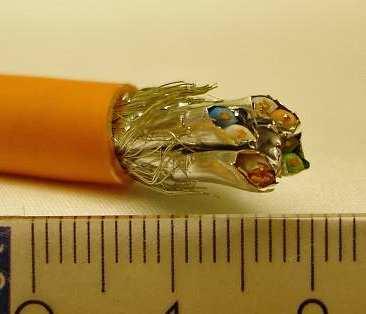
70 7 9 Annex A, Cable details and photographs Cable number C/1/1 C/1/2 C/1/3 Cable group Screened and unscreened data cables Screened and unscreened data cables Screened and unscreened data cables Conductors 4pU/UTP 4pU/UTP 4pF/UTPC5 χ Cable number C/1/4 C/1/5 C/1/6 Cable group Screened and unscreened data cables Screened and unscreened data cables Screened and unscreened data cables Conductors 4pF/UTPC5 4pU/UTP6 4pF/UTPC6 χ Cable number C/1/8 C/1/9 C/1/11 Cable group Screened and unscreened data cables Screened and unscreened data cables Screened and unscreened data cables Conductors 4pF/UTPC6 4pSF/UTP 4pS/FTP χ


71 71 Cable number C/1/12 C/1/13 C/1/14 Cable group Screened and unscreened data cables Screened and unscreened data cables Screened and unscreened data cables Conductors 4pS/FTPC7 4pS/FTPC7 4pS/FTPC7 χ Cable number C/1/15 C/1/16 C/3/1 Cable group Screened and unscreened data cables Screened and unscreened data cables Optical fibre cables Conductors 4pS/FTPC7 32pF/UTPC5 Central tube 2 fibre χ Cable number C/3/2 C/3/3 C/3/4 Cable group Optical fibre cables Optical fibre cables Optical fibre cables Conductors Central tube 12 fibre Central tube 24 fibre Central tube 12 fibre χ


72 72 Cable number C/3/5 C/3/8 C/3/9 Cable group Optical fibre cables Optical fibre cables Optical fibre cables Conductors Central tube 12 fibre Loose tube 12/24 fibre Loose tube 24 fibre χ Cable number C/3/1 C/3/11 C/3/12 Cable group Optical fibre cables Optical fibre cables Optical fibre cables Conductors Loose tube 6 fibre Corrugated tube 6/72 fibre Corrugated tube 6/72 fibre χ Cable number C/3/13 C/3/14 C/3/15 Cable group Optical fibre cables Optical fibre cables Optical fibre cables Conductors Corrugated tube 12/144 fibre Tight buffer 6 fibre Tight buffer 12 fibre χ


73 73 Cable number C/3/16 C/3/17 C/5/1 Cable group Optical fibre cables Optical fibre cables Armoured multicore power cables with copper conductors - PVC Conductors Tight buffer 24 fibre Tight buffer 12 fibre 2 x 1.5 χ 21.3 Cable number C/5/2 C/5/3 C/5/4 Cable group Armoured multicore power cables with copper conductors - PVC Armoured multicore power cables with copper conductors - PVC Armoured multicore power cables with copper conductors - PVC Conductors 4 x 4. 4 x 1 4 x 25 χ Cable number C/5/5 C/5/6 C/5/7 Cable group Armoured multicore power cables with copper conductors - PVC Armoured multicore power cables with copper conductors - PVC Armoured multicore power cables with copper conductors - PVC Conductors 4 x 5 4 x x 1.5 χ


74 74 Cable number C/6/1 C/6/2 C/6/3 Cable group Armoured multicore power cables with copper conductors - Halogen free Armoured multicore power cables with copper conductors - Halogen free Armoured multicore power cables with copper conductors - Halogen free Conductors 2 x x 4. 4 x 1 χ Cable number C/6/4 C/6/5 C/6/6 Cable group Armoured multicore power cables with copper conductors - Halogen free Armoured multicore power cables with copper conductors - Halogen free Armoured multicore power cables with copper conductors - Halogen free Conductors 4 x 25 4 x 5 4 x 24 χ


75 75 Cable number C/6/7 C/7/1 C/7/2 Cable group Armoured multicore power cables with copper conductors - Halogen free Unarmoured multicore power cables with copper conductors - PVC Unarmoured multicore power cables with copper conductors - PVC Conductors 19 x x x 1.5 χ Cable number C/7/3 C/7/4 C/7/5 Cable group Unarmoured multicore power cables with copper conductors - PVC Unarmoured multicore power cables with copper conductors - PVC Unarmoured multicore power cables with copper conductors - PVC Conductors 3 x x 4. 5 x 16 χ


76 76 Cable number C/7/6 C/7/7 C/7/8 Cable group Unarmoured multicore power cables with copper conductors - PVC Unarmoured multicore power cables with copper conductors - PVC Unarmoured multicore power cables with copper conductors - PVC Conductors 4 x 35 4 x 5 4 x 185 χ Cable number C/8a/1 C/8a/2 C/8a/3 Cable group Unarmoured multicore power cables with copper conductors - halogen free Unarmoured multicore power cables with copper conductors - halogen free Unarmoured multicore power cables with copper conductors - halogen free Conductors 2 x x x 2.5 χ


77 77 Cable number C/8a/4 C/8a/5 C/8a/6 Cable group Unarmoured multicore power cables with copper conductors - halogen free Unarmoured multicore power cables with copper conductors - halogen free Unarmoured multicore power cables with copper conductors - halogen free Conductors 4 x 4. 5 x 16 4 x 35 χ Cable number C/8a/7 C/8a/8 C/8b/1 Cable group Unarmoured multicore power cables with copper conductors - halogen free Unarmoured multicore power cables with copper conductors - halogen free Unarmoured multicore power cables with copper conductors - halogen free Conductors 4 x 5 5 x 15 2 x 1.5 χ


78 78 Cable number C/8b/2 C/8b/3 C/8b/4 Cable group Unarmoured multicore power cables with copper conductors - halogen free Unarmoured multicore power cables with copper conductors - halogen free Unarmoured multicore power cables with copper conductors - halogen free Conductors 7 x x x 4. χ Cable number C/8b/5 C/8b/6 C/8b/7 Cable group Unarmoured multicore power cables with copper conductors - halogen free Unarmoured multicore power cables with copper conductors - halogen free Unarmoured multicore power cables with copper conductors - halogen free Conductors 5 x 16 4 x 35 4 x 5 χ


79 79 Cable number C/8b/8 C/9/1 C/9/2 Cable group Unarmoured multicore power cables with copper conductors - halogen free Single core sheathed power cables - PVC with copper conductor Single core sheathed power cables - PVC with copper conductor Conductors 4 x 15 1 x x 4 χ Cable number C/9/3 C/9/4 C/9/5 Cable group Single core sheathed power cables - PVC with copper conductor Single core sheathed power cables - PVC with copper conductor Single core sheathed power cables - PVC with copper conductor Conductors 1 x 1 1 x 25 1 x 5 χ


80 8 Cable number C/9/6 C/9/7 C/9/8 Cable group Single core sheathed power cables - PVC with copper conductor Single core sheathed power cables - PVC with copper conductor Single core sheathed power cables - PVC with copper conductor Conductors 1 x 95 1 x 15 1 x 24 χ Cable number C/1/1 C/1/2 C/1/3 Cable group Single core sheathed power cables - halogen free with copper conductor Single core sheathed power cables - halogen free with copper conductor Single core sheathed power cables - halogen free with copper conductor Conductors 1 x x 6 1 x 1 χ


81 81 Cable number C/1/4 C/1/5 C/1/6 Cable group Single core sheathed power cables - halogen free with copper conductor Single core sheathed power cables - halogen free with copper conductor Single core sheathed power cables - halogen free with aluminium conductor Conductors 1 x 25 1 x 7 1 x 7 χ Cable number C/1/7 C/1/8 C/1/9 Cable group Single core sheathed power cables - halogen free with copper conductor Single core sheathed power cables - halogen free with aluminium conductor Single core sheathed power cables - halogen free with copper conductor Conductors 1 x 95 1 x 95 1 x 15 χ


82 82 Cable number C/1/1 C/1/11 C/1/12 Cable group Single core sheathed power cables - halogen free with aluminium conductor Single core sheathed power cables - halogen free with copper conductor Single core sheathed power cables - halogen free with aluminium conductor Conductors 1 x 15 1 x 24 1 x 24 χ Cable number C/11/1 C/11/2 C/11/3 Cable group Single core unsheathed power cables with copper conductor - PVC Single core unsheathed power cables with copper conductor - PVC Single core unsheathed power cables with copper conductor - PVC Conductors 1 x x 4 1 x 1 χ


83 83 Cable number C/11/4 C/11/5 C/11/6 Cable group Single core unsheathed power cables with copper conductor - PVC Single core unsheathed power cables with copper conductor - PVC Single core unsheathed power cables with copper conductor - PVC Conductors 1 x 25 1 x 5 1 x 95 χ Cable number C/11/7 C/11/8 C/12/1 Cable group Single core unsheathed power cables with copper conductor - PVC Single core unsheathed power cables with copper conductor - PVC Single core unsheathed power cables with copper conductor - halogen free Conductors 1 x 15 1 x 24 1 x 1.5 χ


84 84 Cable number C/12/2 C/12/3 C/12/4 Cable group Single core unsheathed power cables with copper conductor - halogen free Single core unsheathed power cables with copper conductor - halogen free Single core unsheathed power cables with copper conductor - halogen free Conductors 1 x 4 1 x 1 1 x 25 χ Cable number C/12/5 C/12/6 C/12/7 Cable group Single core unsheathed power cables with copper conductor - halogen free Single core unsheathed power cables with copper conductor - halogen free Single core unsheathed power cables with copper conductor - halogen free Conductors 1 x 5 1 x 95 1 x 15 χ


85 85 Cable number C/13/1 C/13/2 C/13/3 Cable group Unarmoured multicore power cables with copper conductors - halogen free Unarmoured multicore power cables with copper conductors - halogen free Unarmoured multicore power cables with copper conductors - halogen free Conductors 2 x x 1 4 x 25 χ Cable number C/13/4 C/13/5 C/13/6 Cable group Unarmoured multicore power cables with copper conductors - halogen free Unarmoured multicore power cables with copper conductors - halogen free Unarmoured multicore power cables with copper conductors - halogen free Conductors 2 x x 1 4 x 25 χ


86 86 Cable number C/13/7 C/13/8 C/13/9 Cable group Unarmoured multicore power cables with copper conductors - halogen free Unarmoured multicore power cables with copper conductors - halogen free Unarmoured multicore power cables with copper conductors - halogen free Conductors 2 x x 1 4 x 25 χ Cable number C/13/1 C/13/11 C/13/12 Cable group Unarmoured multicore power cables with copper conductors - halogen free Unarmoured multicore power cables with copper conductors - halogen free Unarmoured multicore power cables with copper conductors - halogen free Conductors 5 x x 1 5 x 16 χ
87 87 1 Annex B, Test results EN and EN Group number and description Cable ref Cable parameters Test results Conductors Outer dia. (mm) EN (H in mm) EN (T in %) 1 screened and unscreened data cables 2 copper telecommunication PVC and halogen free 3st optical fibre cables 3lt optical fibre cables C/1/1 4pU/UTP C/1/2 4pU/UTP 6 C/1/3 4pF/UTPC C/1/4 4pF/UTPC C/1/5 4pF/UTPC C/1/6 4pF/UTPC C/1/7 4pF/UTPC6 Not used C/1/8 4pF/UTPC6 6.1 C/1/9 4pSF/UTP 6.1 C/1/1 4pSF/UTP Not used C/1/11 4pS/FTP C/1/12 4pS/FTPC C/1/13 4pS/FTPC C/1/14 4pS/FTPC C/1/15 4pS/FTPC C/1/16 32pF/UTPC No cables were supplied in this Group. C/3/1 Central tube 2 fibre C/3/2 Central tube 12 fibre C/3/3 Central tube 24 fibre C/3/4 Central tube 12 fibre C/3/5 Central tube 12 fibre C/3/6 Loose tube x fibre C/3/7 Loose tube y fibre C/3/8 Loose tube 12/24 fibre C/3/9 Loose tube 24 fibre C/3/1 Loose tube 6 fibre Not used Not used
88 88 3ct optical fibre cables 3tb optical fibre cables C/3/11 Corrugated loose buffer tube 6/72 C/3/12 Corrugated loose buffer tube 6/72 C/3/13 Corrugated loose buffer tube 12/144 C/3/14 Tight buffer 6 fibre C/3/15 Tight buffer 12 fibre C/3/16 Tight buffer 24 fibre C/3/17 Tight buffer 12 fibre 4 co-axial cables No cables were supplied in this Group. 5 armoured multicore power cables with copper conductors PVC 6 armoured multicore power cables with copper conductors halogen free 7 unarmoured multicore power cables with copper conductors PVC 8a unarmoured multicore power cables with copper conductors halogen free C/5/1 2 x C/5/2 4 x C/5/3 4 x C/5/4 4 x C/5/5 4 x C/5/6 4 x C/5/7 27 x C/6/1 2 x C/6/2 4 x C/6/3 4 x C/6/4 4 x C/6/5 4 x C/6/6 4 x C/6/7 19 x C/7/1 2 x C/7/2 7 x C/7/3 3 x C/7/4 4 x C/7/5 5 x C/7/6 4 x C/7/7 4 x C/7/8 4 x C/8a/1 2 x C/8a/2 7 x C/8a/3 3 x C/8a/4 4 x C/8a/5 5 x C/8a/6 4 x C/8a/7 4 x C/8a/8 5 x
89 89 8b unarmoured multicore power cables with copper conductors halogen free 9 single core sheathed power cables with copper conductor PVC 1 single core sheathed power cables with copper conductor halogen free 1 single core sheathed power cables with aluminium conductor halogen free 11 single core unsheathed power cables with copper conductor PVC 12 single core unsheathed power cables with copper conductor halogen free C/8b/1 2 x C/8b/2 7 x C/8b/3 3 x C/8b/4 4 x C/8b/5 5 x C/8b/6 4 x C/8b/7 4 x C/8b/8 4 x C/9/1 1 x C/9/2 1 x C/9/3 1 x C/9/4 1 x C/9/5 1 x C/9/6 1 x C/9/7 1 x C/9/8 1 x C/1/1 1 x C/1/2 1 x C/1/3 1 x C/1/4 1 x C/1/5 1 x C/1/7 1 x C/1/9 1 x C/1/11 1 x C/1/6 1 x 7 Al C/1/8 1 x 95 Al C/1/1 1 x 15 Al C/1/12 1 x 24 Al C/11/1 1 x C/11/2 1 x C/11/3 1 x C/11/4 1 x C/11/5 1 x C/11/6 1 x C/11/7 1 x C/11/8 1 x C/12/1 1 x C/12/2 1 x C/12/3 1 x C/12/4 1 x C/12/5 1 x C/12/6 1 x C/12/7 1 x C/12/8 1 x
90 9 13 unarmoured multicore power cables with copper conductors halogen free C/13/1 2 x C/13/2 3 x C/13/3 4 x C/13/4 2 x C/13/5 3 x C/13/6 4 x C/13/7 2 x C/13/8 3 x C/13/9 4 x C/13/1 5 x C/13/11 4 x C/13/12 5 x
91 91 11 Annex C, Analysis of results In Sections , the results from the tests performed within the CEMAC project are presented. Each section contains the analysis of the required safety margins for peak HRR, THR, FIGRA, Flame spread, peak SPR, and TSP. In each section all tested cable families are analyzed. The straight lines in the graphs show the worst case for that particular classification parameter and each particular cable group. By worst case is meant the biggest error that can be made by assuming that all cables with cable parameter χ between the tested cables are classified according to the worst result of the two tested cables. The projection on the vertical axis of the red line defines the particular safety margin. Safety margins are different in the different classes B2 ca, C ca, D ca, s1, and s2. The reason for this is the variation is typically larger when the test results have higher values. Therefore in general the safety margins are lower for the better classes. Cables with class worse than D ca (C ca for flame spread) or s2 are not considered. Table 52 to Table 56 shows the required safety margins for the different classification parameters and for all tested cable families within CEMAC. If is reported this means that no safety margin is required based on the tested cables or no cables fall in the particular class. In Table 57 to Table 61 the data have been reduced to only specify the safety margin for each generic family, not for each tested cable group. It is clear that safety margins are relatively low, with a few exceptions. Based on these results a conservative way of determining the safety margin is to define it as 1 % of the class limit for flame and heat release classification parameters, that is peak HRR, THR, FIGRA and Flame spread, and 2 % of the class limits for smoke classification parameters, that is peak SPR and TSP. This gives the following definitions of ν sm: Table 5 Summary of vsm to be used in EXAP. B2 ca C ca D ca S1 S2 Peak HRR [kw] THR [MJ] FIGRA [Ws -1 ] Flame spread [m].15.2 Peak SPR [m 2 s -1 ].5.3 TSP [m 2 ] 1 8 Although some of the experimentally determined safety margins in Table 57 to Table 6 are much higher than those chosen in Table 5 very few incorrect classifications occur for the tested cables. The explanation to this is that the actually measured results are well below the class limits. A quantitative measure of how reliable the EXAP rules become with the safety margins in Table 5 is given below. It should be remembered that this measure is solely based on the actual tests performed within the CEMAC project. No validation to other tests has been performed.
92 92 Table 51 Error rate for the different classification parameters. Total number of Number of incorrect combinations classifications Percentage of incorrect classifications Peak HRR [kw] 166 THR [MJ] 166 FIGRA [Ws -1 ] % Flame spread [m] % Peak SPR [m 2 s -1 ] % TSP [m 2 ] % The error rates reported in Table 51 are given for each individual classification parameter. As can be seen the number of incorrectly classifications is very low for all parameter. Furthermore if a cable should be erroneously classified as for example B2 ca while in reality it is C ca it must be classified as B2 ca for all classification parameters peak HRR, THR, FIGRA, and Flame spread. The confidence of the EXAP procedure is therefore high. Table 52 νsm for class B2ca based on the test results in the CEMAC project for each individual cable group. Armoured Unarmoured multicore Single core sheathed Single core unsheathed Group a 8b Peak HRR THR 2 3 FIGRA Flame Spread Table 53 νsm for class Cca based on the test results in the CEMAC project for each individual cable group. Armoured Unarmoured multicore Single core sheathed Single core unsheathed a 8b Peak HRR THR 4 7 FIGRA Flame Spread.1 Table 54 νsm for class Dca based on the test results in the CEMAC project for each individual cable group. Armoured Unarmoured multicore Single core sheathed Single core unsheathed a 8b Peak HRR THR 8 5 FIGRA Flame Spread NA NA NA NA NA NA NA NA NA
93 93 Table 55 νsm for class s1 based on the test results in the CEMAC project for each individual cable group. Armoured Unarmoured multicore Single core sheathed Single core unsheathed a 8b Peak SPR TSP Table 56 νsm for class s2 based on the test results in the CEMAC project for each individual cable group. Armoured Unarmoured multicore Single core sheathed Single core unsheathed a 8b Peak SPR TSP Table 57 Maximum νsm for class B2ca based on the test results in the CEMAC for the different construction types. Class limit Armoured Unarmoured multicore Single core sheathed Single core unsheathed Peak HRR THR 15 3 FIGRA Flame Spread Table 58 Maximum νsm for class Cca based on the test results in the CEMAC for the different construction types. Class limit Armoured Unarmoured multicore Single core sheathed Single core unsheathed Peak HRR THR FIGRA Flame Spread 2.1 Table 59 Maximum νsm for class Dca based on the test results in the CEMAC for the different construction types. Class limit Armoured Unarmoured multicore Single core sheathed Single core unsheathed Peak HRR THR FIGRA 13
94 94 Table 6 Maximum νsm for class s1 based on the test results in the CEMAC for the different construction types. Class limit Armoured Unarmoured multicore Single core sheathed Single core unsheathed Peak SPR TSP Table 61 Maximum νsm for class s2 based on the test results in the CEMAC for the different construction types. Class limit Armoured Unarmoured multicore Single core sheathed Single core unsheathed Peak SPR TSP
95 Peak HRR Table 62 The straight lines in the graphs shows the worst case for each particular cable group. By worst case is meant the biggest error that can be made by assuming that all cables with cable parameter χ between the tested cables are classified according to the worst result of the two tested cables. The projection of the red line on the vertical axis defines the particular safety margin. Group 5 peak HRR [kw] B2 3 kw C 6 kw D 4 kw 11 peak HRR [kw] D χ Group 6 peak HRR [kw] B2 3 kw C 6 kw D 4 kw 18.5 peak HRR [kw] C χ
96 Group 7 peak HRR [kw] B2 3 kw C 6 kw D 4 kw peak HRR [kw] χ C Group 8a peak HRR [kw] B2 3 kw C 6 kw D 4 kw peak HRR [kw] B χ 35 3 Group 8b peak HRR [kw] B2 3 kw C 6 kw D 4 kw 65.4 peak HRR [kw] D χ
97 97 Group 9 peak HRR [kw] B2 3 kw C 6 kw D 4 kw peak HRR [kw] χ 25 Group 1Cu peak HRR [kw] 2 B2 3 kw C 6 kw D 4 kw 3. peak HRR [kw] C χ 35 3 Group 11 peak HRR [kw] B2 3 kw C 6 kw D 4 kw 1.5 peak HRR [kw] B χ
98 98 Group 12 peak HRR [kw] B2 3 kw C 6 kw D 4 kw 3.4 peak HRR [kw] B χ
99 THR Table 63 The straight lines in the graphs shows the worst case for each particular cable group. By worst case is meant the biggest error that can be made by assuming that all cables with cable parameter χ between the tested cables are classified according to the worst result of the two tested cables. The projection of the red line on the vertical axis defines the particular safety margin Group 5 THR [MJ] B2: 15MJ C: 3MJ D: 7MJ THR [MJ] χ Group 6 THR [MJ] B2: 15MJ C: 3MJ D: 7MJ 3.6 THR [MJ] C χ 9 8 Group 7 THR [MJ] B2: 15MJ C: 3MJ D: 7MJ THR [MJ] χ
100 1 6 Group 8a THR [MJ] B2: 15MJ C: 3MJ D: 7MJ 7.7 THR [MJ] D χ 12 Group 8b THR [MJ] B2: 15MJ C: 3MJ D: 7MJ THR [MJ] χ 12 Group 9 THR [MJ] B2: 15MJ C: 3MJ D: 7MJ 1 THR 8 [MJ] χ
101 11 Group 1Cu THR [MJ] B2: 15MJ C: 3MJ D: 7MJ THR [MJ] C D χ 9 8 Group 11 THR [MJ] B2: 15MJ C: 3MJ D: 7MJ 1.6 THR [MJ] 7 B χ 12 1 B2 Group 12 THR [MJ] B2: 15MJ C: 3MJ D: 7MJ 2.7 THR [MJ] χ
102 FIGRA Table 64 The straight lines in the graphs shows the worst case for each particular cable group. By worst case is meant the biggest error that can be made by assuming that all cables with cable parameter χ between the tested cables are classified according to the worst result of the two tested cables. The projection of the red line on the vertical axis defines the particular safety margin Group 5 FIGRA [W/s] B2 15 C 3 D FIGRA [W/s] 12 C B χ Group 6 FIGRA [W/s] B2 15 C 3 D FIGRA [W/s] B χ Group 7 FIGRA [W/s] B2 15 C 3 D FIGRA [W/s] B χ
103 B2 Group 8a FIGRA [W/s] B2 15 C 3 D FIGRA [W/s] χ Group 8b FIGRA [W/s] B2 15 C 3 D FIGRA [W/s] B χ C 4 Group 9 FIGRA [W/s] B2 15 C 3 D 13 FIGRA [W/s] χ
104 Group 1Cu FIGRA [W/s] B2 15 C 3 D FIGRA [W/s] B χ 35 3 Group 11 FIGRA [W/s] B2 15 C 3 D 13 FIGRA [W/s] χ Group 12 FIGRA [W/s] 1 B2 15 C 3 D FIGRA [W/s] B χ
105 Flame spread Table 65 The straight lines in the graphs shows the worst case for each particular cable group. By worst case is meant the biggest error that can be made by assuming that all cables with cable parameter χ between the tested cables are classified according to the worst result of the two tested cables. The projection of the red line on the vertical axis defines the particular safety margin. 3.5 Group 5 Damaged Length [m] B2 1.5m C 2m Damaged length [m] χ Group 6 - Damaged Length [m] B2 1.5m C 2m.5 Damaged length [m] 1.8 C χ Group 7 Damaged Length [m] B2 1.5m C 2m Damaged length [m] χ
106 Group 8a Damaged Length [m] B2 1.5m C 2m Damaged length [m] χ Group 8b Damaged Length [m] B2 1.5m C 2m.8 Damaged length [m] B χ 3.5 Group 9 Damaged Length [m] B2 1.5m C 2m Damaged length [m] χ
107 Group 1Cu- Damaged Length [m] B2 1.5m C 2m.3 Damaged length [m] B χ B2 Group 11 Damaged Length [m] B2 1.5m C 2m.15 Damaged length [m] χ Group 12 Damaged Length [m] B2 1.5m C 2m.15 Damaged length [m] B χ
108 Peak SPR Table 66 The straight lines in the graphs shows the worst case for each particular cable group. By worst case is meant the biggest error that can be made by assuming that all cables with cable parameter χ between the tested cables are classified according to the worst result of the two tested cables. The projection of the red line on the vertical axis defines the particular safety margin. Group 5 peak SPR [m 2 /s] s1,25 s2 1, Peak SPR [m 2 /s] S χ.12 Group 6 - peak SPR [m 2 /s] s1,25 s2 1,5.25 Peak SPR [m 2 /s] S χ Group 7 peak SPR [m 2 /s] s1,25 s2 1,5.5 Peak SPR [m 2 /s] S χ
109 19 Group 8a peak SPR [m 2 /s] s1,25 s2 1,5.9 Peak SPR [m 2 /s] S χ Group 8b peak SPR [m 2 /s] s1,25 s2 1, Peak SPR [m 2 /s] S S χ 6 5 Group 9 peak SPR [m 2 /s] s1,25 s2 1,5 Peak SPR [m 2 /s] χ
110 11 Group 1Cu- peak SPR [m 2 /s] s1,25 s2 1,5.23 Peak SPR [m 2 /s] S χ Group 11 peak SPR [m 2 /s] s1,25 s2 1, Peak SPR [m 2 /s] S χ.6 Group 12 peak SPR [m 2 /s] s1,25 s2 1,5 Peak SPR [m 2 /s] χ
111 TSP Table 67 The straight lines in the graphs shows the worst case for each particular cable group. By worst case is meant the biggest error that can be made by assuming that all cables with cable parameter (d or χ) between the tested cables are classified according to the worst result of the two tested cables. The projection of the red line on the vertical axis defines the particular safety margin. 8 Group 5 TSP [m 2 ] s1 5 s TSP [m 2 ] S χ 6 Group 6 - TSP [m 2 ] s1 5 s TSP [m 2 ] S χ Group 7 TSP [m 2 ] s1 5 s2 4 TSP [m 2 ] χ
112 112 Group 8a TSP [m 2 ] s1 5 s TSP [m 2 ] S1 S χ 25 Group 8b TSP [m 2 ] s1 5 s TSP [m 2 ] S χ 12 1 Group 9 TSP [m 2 ] s1 5 s2 4 TSP [m 2 ] χ
113 113 Group 1Cu- TSP [m 2 ] s1 5 s TSP [m 2 ] 1 9 S S χ Group 11 TSP [m 2 ] s1 5 s TSP [m 2 ] S χ 3 Group 12 TSP [m 2 ] s1 5 s TSP [m 2 ] S χ


114 Annex D, Proposal for EXAP rules for power cables The EXAP procedure is described in the flow chart in Figure 28. The EXAP is applicable to FIPEC Scenario 1, i.e. for Class B2 ca, C ca and D ca cables. Figure 28 Flow chart of the EXAP procedure Definition of a product family for EXAP for power cables For the purposes of applying the EXAP rules and procedure, a cable family should be defined as follows: A family of cables is a specific range of products of the same general construction and varying only in conductor size and number of cores. The specific family shall be produced by the same manufacturer using the same materials and the same design rules (International standard, National standard, Company standard based on National or International standard).
115 115 If the cable family falls under one of the generic families: - single core unsheathed - single core sheathed - unarmoured multicore - armoured multicore the specific EXAP with safety margin as a function of classification parameter and class may be applied. The full constructional and material details for the family shall be submitted to the certification body prior to the EXAP being applied EXAP with safety margin An EXAP is based on two or more tests. The parameter χ is used as independent cable parameter. χ is defined as: χ = c 2 d V combust where d [m] Outer diameter. V combust [m 2 ] Non-metallic volume per meter ladder. c [] Number of conductors in one cable. An EXAP is based on two or more tests. All cables within the same family with a value of the cable parameter between the lowest and highest value of the cable parameters of the tested cables are included in the EXAP. Classification is based on the maximum measured value plus a safety margin: class = ν max ν sm ν + where ν class ν max ν sm is the value used for classification according to respective classification parameter (peak HRR, THR, FIGRA, FS, peak SPR, and TSP), is the maximum, that is the worst, test results of the tests that forms the basis of the EXAP, and is the safety margin required for the particular classification parameter.
116 116 The safety margins for the different classes and classification parameters are given in Table Table 68. Table 68 Safety margins vsm. B2 C D S1 S2 Peak HRR [kw] THR [MJ] FIGRA [Ws -1 ] Flame spread [m].15.2 Peak SPR [m 2 s -1 ].5.3 TSP [m 2 ] 1 8 These safety margins can be applied to cables with cable parameter within the ranges indicated in Table 69. An exception is very large cables, see Section Table 69 Allowed range of cable parameters for using safety margins as specified in Table 68. d min [mm] d max [mm] χ min [ ] χ max [ ] Armoured 1 (5) Unarmoured 9 (5) multicore Single core 6 (5) sheathed Single core unsheathed The value 5 mm given in the parentheses in the d min column are only applicably if the flame spread for the tested cables with diameters less than those tested in the CEMAC project is less than 3.3 m, that is if the cables are not fully combusted. Cables with a diameter of exactly 5 mm, or less, must be bundled according to pren Bundled cables are not included in the specific EXAP rules as the fire performance changes dramatically with the change of mounting. Therefore these cables need to be tested case by case.
117 117 Figure 29 shows a theoretical example for how ν class for the classification parameter TSP is assessed for a cable group. Tests are performed for cables with χ = 1 and with χ = 5. The maximum result is TSP = 3 m 2 which is obtained for χ = 5. Therefore ν max = 3 m 2. ν sm for TSP class s2 is 8 m 2 according to Table 68. Assuming that the cables are unarmoured multicore the value for classification would be ν class = = 38 m 2. This is below the limit 4 m 2 for smoke class s2. Therefore, for TSP, all cables in the group with 1 χ 5 can be considered to fulfil the requirement for class s2. In order to classify the cables as s2 they also need to fulfil the requirements for s2 for peak SPR. Figure 29 Assessment of νclass for the classification parameter TSP. The first (χ=1) and the fifth (χ =5) cables are tested and used as basis for the EXAP. This results in a classification value, νclass = νmax+νsm,= 38 m 2, for 1 χ 5, that is lower than the TSP class limit 4 m 2 for class s2. Theoretical example.
118 Cables larger than the tested range Cables larger than the tested range are not included in the applicable range for safety margins in Table 69. At the same time it is well known that, as long as not all cables within a group are completely combusted, fire performance is better for larger cables than for smaller cables. There is therefore a possibility for EXAP based on extrapolation to larger diameters for cable families listed in Table 41. The condition for this is that fire performance actually improves with increasing diameter. This condition is in general fulfilled if the classification for a large diameter cable is B2 ca or C ca. A cable is considered to have a large diameter if its diameter d max is within the range given in Table 7. Table 7 Allowed ranges of dmax for EXAP applied for very large cables. Armoured cables: d max = mm Unarmoured multicore cables d max = mm Single core sheathed cables d max = mm Single core unsheathed cables d max = mm If a cable with outer diameter d max in the range given in Table 7 is tested and classified B2 ca or C ca then cables with d>d max can be classified according to the result for the tested cable with diameter d max Generic rules For cable types not belonging to any of the cable families defined in in Table 41 no safety margins have been determined. For such cables safety margins can be generated from the test results of the tested cables. In this case at least three cables must be tested. The generic EXAP is based on the cable parameter χ. Therefore the cables in the cable family need a well defined diameter. This means that the cable cross section must be circular. Furthermore the cables need a well defined non-zero number of metallic conductors. As a result the generic EXAP rules can only be applied for cable families with circular cables having at least one metallic conductor. For other type of cable families it is not possible with EXAP. The generic EXAP is not applicable to data or optical cables.
119 119 The safety margin ν sm is a function that: increases with increased dispersion of the measured values, increases with increased range of the cable parameter χ, decreases with increased number of tests, and decreases with increased monotonicity of the measured values. Such a function is shown in Equation 1 below: σ ( χ max χ min 1) ( n 1) χ min ( 1 m) v sm = + where (1) σ is the standard variation of the measured values, χ min and χ max are the limiting cable parameters in the tested range, n is the number of tested cables, n 3, and m is a measure of the monotonicity of the measured values. σ = 1 n ( v i v ) n i= 1 2 m n 1 v i+ 1 i= 1 = 1 n 1 i= 1 v v i i+ 1 v v n i v (If all values are identical m=1.) 1
120 12 χ χ Selection of cable parameter, n=3 cables The cable parameter of the tested cables with a value of the cable parameter between χ min and χ max can not be chosen arbitrarily. If three cables are tested the cable parameter of the third cable must fall in the following range: χ χ = 2 ( χ + χ ). ( χ χ ) min = max min 1 max min ( χ + χ ) +. ( χ χ ) max max min 1 max min Selection of cable parameters, n>3 cables If four or more cables are tested the cable parameter must fall in the following range: i 1 χ n 1 n 3 χ χ 2 n 2 1 χ χ 2 n 2 max min max min ( n 2) χ 1 + χ ( 2 i) ) + 1 ( i 3) ni, min = max + min ( 3) min n ( n 3) i 1 n 1 χ Where n 3 χ 2 χ ( n 2 1 χ 2 max min max min ( n 2) χ 1 χ ( 2 i) ) + 1 ( i 1) ni, max = max + min 3) min 3) n 2 + χ n ( n 2 n i is the total number of cables tested, including the cables with the extreme cable parameters χ min and χ max. is a counter for the cables tested, where i=2, 3,, n-1. i=1 and i=n are reserved for the extreme cable parameters, that is, χ n1=χ min and χ nn=χ max. χ ni, min is the minimum cable parameter for the i-th cable. χ ni, max is the maximum cable parameter for the i-th cable. Except for the determination of safety margin the classification is performed in the same way as is described in Section 7.1. The EXAP is only valid for cables within the range χ min χ χ max.
121 121 Example 1 Three cables are tested. The cable parameter χ of the cables are χ 1=6.1, χ 2=21.8, and χ 3=33. FIGRA for these cables are measured to ν 1=38.5 W/s, ν 2=4.5 W/s, and ν 3=13.4 W/s, respectively. This gives: σ = 3.1 W/s, m = 1 ν sm = 33.2 W/s and finally ν class=136.6 W/s This shows that the value for classification that shall be used for FIGRA is W/s. This is lower than the classification criterion 15 W/s for class B2 ca. Therefore, for FIGRA, all cables in the group with 6.1 χ 33 can be considered to fulfil the requirement for class B2 ca. In order to classify the cables as B2 ca they also need to fulfil the requirements for B2 ca for flame spread, peak HRR, FIGRA and for EN The example is taken from actual tests on cable group 7. The experimental results are shown in Figure 3 where the red circles indicate the cables used in the example. Figure 3 FIGRA for cable group 7. The full range of experimental results is indicated with diamonds whereas the red circles indicate the cables used for the generic EXAP procedure in the example.
122 122 Example 2 Three cables are tested. The cable parameter χ of the cables are χ 1=8.8, χ 2=18.2, and χ 3=33.2. TSP for these cables are measured to ν 1=16.3 m 2, ν 2=16.3 m 2, and ν 3=45.4 m 2, respectively. This gives: σ = 13.7 m 2, m = 1 ν sm = 9.1 m² and finally ν class=54.5 m 2 This shows that the value for classification that shall be used for TSP is 54.5 m 2. This is higher than the classification criterion 5 m 2 for class s1. Therefore, cables in the group with 8.8 χ 33.2 can not be considered to fulfil the requirement for class s1. The example is taken from actual tests on cable group 8a. The experimental results are shown in Figure 31 where the red circles indicate the cables used in the example. Figure 31 TSP for cable group 8a. The full range of experimental results is indicated with diamonds whereas the red circles indicate the cables used for the generic EXAP procedure in the example Flaming droplets/particles For flaming droplets/particles the cables within the cable parameter range for the EXAP are classified according to the worst result for the tested cables within this range.
123 Annex E, Summary graphs of cable group test results and table of main scalar values, RTD Group 1 Group 1: Screened & Unscreened data cables HRR HRR 3 (kw) pU/UTP (1) 4pU/UTP (1) 4pF/UTPC5 (1) 4pF/UTPC5 (1) 4pF/UTPC6 (1) 4pF/UTPC6 (1) 4pF/UTPC6 (1) 4pSF/UTP (1) 4pS/STP (1) 4pS/FTPC7 (1) 4pS/FTPC7 (1) 4pS/FTPC7 (1) 4pS/FTPC7 (1) 32pF/UTPC5 (1) time (s) Group 1: Screened & Unscreened data cables THR 7 THR (MJ) pU/UTP (1) 4pU/UTP (1) 4pF/UTPC5 (1) 4pF/UTPC5 (1) 4pF/UTPC6 (1) 4pF/UTPC6 (1) 4pF/UTPC6 (1) 4pSF/UTP (1) 4pS/STP (1) 4pS/FTPC7 (1) 4pS/FTPC7 (1) 4pS/FTPC7 (1) 4pS/FTPC7 (1) 32pF/UTPC5 (1) time (s)
124 124 Group 1: Screened & Unscreened data cables FIGRA 25 FIGRA (W/s) pU/UTP (1) 4pU/UTP (1) 4pF/UTPC5 (1) 4pF/UTPC5 (1) 4pF/UTPC6 (1) 4pF/UTPC6 (1) 4pF/UTPC6 (1) 4pSF/UTP (1) 4pS/STP (1) 4pS/FTPC7 (1) 4pS/FTPC7 (1) 4pS/FTPC7 (1) 4pS/FTPC7 (1) 32pF/UTPC5 (1) time (s) Group 1: Screened & Unscreened data cables SPR SPR 6 (m²/s) pU/UTP (1) 4pU/UTP (1) 4pF/UTPC5 (1) 4pF/UTPC5 (1) 4pF/UTPC6 (1) 4pF/UTPC6 (1) 4pF/UTPC6 (1) 4pSF/UTP (1) 4pS/STP (1) 4pS/FTPC7 (1) 4pS/FTPC7 (1) 4pS/FTPC7 (1) 4pS/FTPC7 (1) 32pF/UTPC5 (1) time (s)
125 125 Group 1: Screened & Unscreened data cables TSP 5 45 TSP (m²) pU/UTP (1) 4pU/UTP (1) 4pF/UTPC5 (1) 4pF/UTPC5 (1) 4pF/UTPC6 (1) 4pF/UTPC6 (1) 4pF/UTPC6 (1) 4pSF/UTP (1) 4pS/STP (1) 4pS/FTPC7 (1) 4pS/FTPC7 (1) 4pS/FTPC7 (1) 4pS/FTPC7 (1) 32pF/UTPC5 (1) time (s)
126 126 Group 3 Group 3: Optical fibre cables HRR 3 35 Central tube 2 fibre (1) 3 25 Central tube 12 fibre (1) Central tube 24 fibre (1) Central tube 12 fibre (1) Central tube 12 fibre (1) HRR 3 (kw) Loose tube 24 fibre (1) Loose tube 6 fibre (1) Corrugated loose buffer tube 6/72 (1) Corrugated loose buffer tube 12/144 (1) Tight buffer 6 fibre (1) 5 Tight buffer 12 fibre (1) Tight buffer 24 fibre (1) time (s) Tight buffer 12 fibre (1) Group 3: Optical fibre cables THR 9 8 Central tube 2 fibre (1) Central tube 12 fibre (1) THR (MJ) Central tube 24 fibre (1) Central tube 12 fibre (1) Central tube 12 fibre (1) Loose tube 24 fibre (1) Loose tube 6 fibre (1) Corrugated loose buffer tube 6/72 (1) Corrugated loose buffer tube 12/144 (1) 2 Tight buffer 6 fibre (1) time (s) Tight buffer 12 fibre (1) Tight buffer 24 fibre (1) Tight buffer 12 fibre (1)
127 127 Group 3 : Optical fibre cables FIGRA 8 Central tube 2 fibre (1) 7 Central tube 12 fibre (1) 6 Central tube 24 fibre (1) Central tube 12 fibre (1) FIGRA (W/s) Central tube 12 fibre (1) Loose tube 24 fibre (1) Loose tube 6 fibre (1) Corrugated loose buffer tube 6/72 (1) Corrugated loose buffer tube 12/144 (1) Tight buffer 6 fibre (1) 1 Tight buffer 12 fibre (1) Tight buffer 24 fibre (1) time (s) Tight buffer 12 fibre (1) Group 3: Optical fibre cables SPR 6 SPR 6 (m²/s) Central tube 2 fibre (1) Central tube 12 fibre (1) Central tube 24 fibre (1) Central tube 12 fibre (1) Central tube 12 fibre (1) Loose tube 24 fibre (1) Loose tube 6 fibre (1) Corrugated loose buffer tube 6/72 (1) Corrugated loose buffer tube 12/144 (1) Tight buffer 6 fibre (1) Tight buffer 12 fibre (1) Tight buffer 24 fibre (1) Tight buffer 12 fibre (1) time (s)
128 128 Group 3: Optical fibre cables TSP Central tube 2 fibre (1) Central tube 12 fibre (1) Central tube 24 fibre (1) Central tube 12 fibre (1) Central tube 12 fibre (1) TSP (m²) Loose tube 24 fibre (1) Loose tube 6 fibre (1) Corrugated loose buffer tube 6/72 (1) Corrugated loose buffer tube 12/144 (1) 4 2 Tight buffer 6 fibre (1) Tight buffer 12 fibre (1) Tight buffer 24 fibre (1) time (s) Tight buffer 12 fibre (1)
129 129 Group 5 Group 5: armoured multicore power cables with copper conductors PVC HRR HRR 3 (kw) x 1.5 (R) 4 x 4. (R) 4 x 1 (R) 4 x 25 (R) 4 x 5 (R) 4 x 24 (R) 27 x 1.5 (R) time (s) Group 5: armoured multicore power cables with copper conductors PVC THR THR (MJ) x 1.5 (R) 4 x 4. (R) 4 x 1 (R) 4 x 25 (R) 4 x 5 (R) 4 x 24 (R) 27 x 1.5 (R) time (s)
130 13 Group 5: armoured multicore power cables with copper conductors PVC FIGRA FIGRA (W/s) x 1.5 (R) 4 x 4. (R) 4 x 1 (R) 4 x 25 (R) 4 x 5 (R) 4 x 24 (R) 27 x 1.5 (R) time (s) Group 5: armoured multicore power cables with copper conductors PVC SPR SPR 6 (m²/s) x 1.5 (R) 4 x 4. (R) 4 x 1 (R) 4 x 25 (R) 4 x 5 (R) 4 x 24 (R) 27 x 1.5 (R) time (s)
131 131 Group 5: armoured multicore power cables with copper conductors PVC TSP TSP (m²) x 1.5 (R) 4 x 4. (R) 4 x 1 (R) 4 x 25 (R) 4 x 5 (R) 4 x 24 (R) 27 x 1.5 (R) time (s)
132 132 Group 6 Group 6: armoured multicore power cables with copper conductors halogen free HRR x 1.5 (R) HRR 3 (kw) x 4 (R) 4 x 1 (R) 4 x 25 (R) 4 x 5 (R) 4 x 24 (R) 19 x 1.5 (R) time (s) Group 6: armoured multicore power cables with copper conductors halogen free THR 3 25 THR (MJ) x 1.5 (R) 4 x 4 (R) 4 x 1 (R) 4 x 25 (R) 4 x 5 (R) 4 x 24 (R) 19 x 1.5 (R) time (s)
133 133 Group 6: armoured multicore power cables with copper conductors halogen free FIGRA 12 1 FIGRA (W/s) x 1.5 (R) 4 x 4 (R) 4 x 1 (R) 4 x 25 (R) 4 x 5 (R) 4 x 24 (R) 19 x 1.5 (R) time (s) Group 6: armoured multicore power cables with copper conductors halogen free SPR SPR 6 (m²/s) x 1.5 (R) 4 x 4 (R) 4 x 1 (R) 4 x 25 (R) 4 x 5 (R) 4 x 24 (R) 19 x 1.5 (R) time (s)
134 134 Group 6: armoured multicore power cables with copper conductors halogen free TSP 6 5 TSP (m²) x 1.5 (R) 4 x 4 (R) 4 x 1 (R) 4 x 25 (R) 4 x 5 (R) 4 x 24 (R) 19 x 1.5 (R) time (s)
135 135 Group 7 Group 7: unarmoured multicore power cables with copper conductors PVC HRR HRR 3 (kw) x 1.5 (1) 7 x 1.5 (1) 3 x 2.5 (1) 4 x 4 (1) 5 x 16 (1) 4 x 35 (1) 4 x 5 (1) 4 x 185 (1) 7x1.5(1) time (s) Group 7: unarmoured multicore power cables with copper conductors PVC THR THR (MJ) x 1.5 (1) 7 x 1.5 (1) 3 x 2.5 (1) 4 x 4 (1) 5 x 16 (1) 4 x 35 (1) 4 x 5 (1) 4 x 185 (1) 7X1.5(1) time (s)
136 136 Group 7: unarmoured multicore power cables with copper conductors PVC FIGRA FIGRA (W/s) x 1.5 (1) 7 x 1.5 (1) 3 x 2.5 (1) 4 x 4 (1) 5 x 16 (1) 4 x 35 (1) 4 x 5 (1) 4 x 185 (1) 7X1.5(1) time (s) Group 7: unarmoured multicore power cables with copper conductors PVC SPR SPR 6 (m²/s) x 1.5 (1) 7 x 1.5 (1) 3 x 2.5 (1) 4 x 4 (1) 5 x 16 (1) 4 x 35 (1) 4 x 5 (1) 4 x 185 (1) 7X1.5(1) time (s)
137 137 Group 7: unarmoured multicore power cables with copper conductors PVC TSP TSP (m²) x 1.5 (1) 7 x 1.5 (1) 3 x 2.5 (1) 4 x 4 (1) 5 x 16 (1) 4 x 35 (1) 4 x 5 (1) 4 x 185 (1) 7X1.5(1) time (s)
138 138 Group 8a Group 8a: unarmoured multicore power cables with copper conductors halogen free HRR HRR 3 (kw) x 1.5 (1) 7 x 1.5 (1) 3 x 2.5 (1) 4 x 4 (1) 4 x 16 (1) 4 x 35 (1) 4 x 5 (1) 3 x 185 (1) 3x2.5(1R) 4x5(1R) time (s) Group 8a: unarmoured multicore power cables with copper conductors halogen free THR 6 5 THR (MJ) x 1.5 (1) 7 x 1.5 (1) 3 x 2.5 (1) 4 x 4 (1) 4 x 16 (1) 4 x 35 (1) 4 x 5 (1) 3 x 185 (1) 3x2.5(1R) 4x5(1R) time (s)
139 139 Group 8a: unarmoured multicore power cables with copper conductors halogen free 14 FIGRA 12 FIGRA (W/s) x 1.5 (1) 7 x 1.5 (1) 3 x 2.5 (1) 4 x 4 (1) 4 x 16 (1) 4 x 35 (1) 4 x 5 (1) 3 x 185 (1) 3x2.5(1R) 4x5(1R) time (s) Group 8a: unarmoured multicore power cables with copper conductors halogen free.16 SPR SPR 6 (m²/s) x 1.5 (1) 7 x 1.5 (1) 3 x 2.5 (1) 4 x 4 (1) 4 x 16 (1) 4 x 35 (1) 4 x 5 (1) 3 x 185 (1) 3x2.5(1R) 4x5(1R) time (s)
140 14 Group 8a: unarmoured multicore power cables with copper conductors halogen free TSP TSP (m²) x 1.5 (1) 7 x 1.5 (1) 3 x 2.5 (1) 4 x 4 (1) 4 x 16 (1) 4 x 35 (1) 4 x 5 (1) 3 x 185 (1) 3x2.5(1R) 4x5(1R) time (s)
141 141 Group 8b Group : 8 B unarmoured multicore power cables with copper conductors halogen free HRR HRR 3 (kw) x 1.5 (1) 7 x 1.5 (1) 3 x 2.5 (1) 4 x 4 (1) 4 x 16 (1) 4 x 35 (1) 4 x 5 (1) 3 x 185 (1) time (s) Group : 8 B unarmoured multicore power cables with copper conductors halogen free THR 12 1 THR (MJ) x 1.5 (1) 7 x 1.5 (1) 3 x 2.5 (1) 4 x 4 (1) 4 x 16 (1) 4 x 35 (1) 4 x 5 (1) 3 x 185 (1) time (s)
142 142 Group : 8 B unarmoured multicore power cables with copper conductors halogen free FIGRA FIGRA (W/s) x 1.5 (1) 7 x 1.5 (1) 3 x 2.5 (1) 4 x 4 (1) 4 x 16 (1) 4 x 35 (1) 4 x 5 (1) 3 x 185 (1) time (s) Group : 8 B unarmoured multicore power cables with copper conductors halogen free SPR SPR 6 (m²/s) x 1.5 (1) 7 x 1.5 (1) 3 x 2.5 (1) 4 x 4 (1) 4 x 16 (1) 4 x 35 (1) 4 x 5 (1) 3 x 185 (1) time (s)
143 143 Group : 8 B unarmoured multicore power cables with copper conductors halogen free TSP 25 2 TSP (m²) x 1.5 (1) 7 x 1.5 (1) 3 x 2.5 (1) 4 x 4 (1) 4 x 16 (1) 4 x 35 (1) 4 x 5 (1) 3 x 185 (1) time (s)
144 144 Group 9 Group 9: single core sheathed power cables with copper conductor PVC HRR HRR 3 (kw) x 1.5 (R) 1 x 4 (R) 1 x 1 (R) 1 x 25 (R) 1 x 5 (R) 1 x 95 (R) 1 x 15 (R) 1 x 24 (R) time (s) Group 9: single core sheathed power cables with copper conductor PVC THR x 1.5 (R) 1 x 4 (R) 8 1 x 1 (R) THR (MJ) 6 1 x 25 (R) 1 x 5 (R) 4 1 x 95 (R) 1 x 15 (R) 2 1 x 24 (R) time (s)
145 145 Group 9: single core sheathed power cables with copper conductor PVC FIGRA x 1.5 (R) 3 1 x 4 (R) FIGRA (W/s) x 1 (R) 1 x 25 (R) 1 x 5 (R) 1 x 95 (R) 1 1 x 15 (R) 5 1 x 24 (R) time (s) Group 9: single core sheathed power cables with copper conductor PVC SPR x 1.5 (R) 5 1 x 4 (R) 1 x 1 (R) SPR 6 (m²/s) x 25 (R) 1 x 5 (R) 1 x 95 (R) 2 1 x 15 (R) 1 1 x 24 (R) time (s)
146 146 Group 9: single core sheathed power cables with copper conductor PVC TSP x 1.5 (R) 1 x 4 (R) 8 1 x 1 (R) TSP (m²) 6 1 x 25 (R) 1 x 5 (R) 4 1 x 95 (R) 1 x 15 (R) 2 1 x 24 (R) time (s)
147 147 Group 1 Group 1: single core sheathed power cables with either copper or aluminium conductor halogen free HRR x 2.5 (R) HRR 3 (kw) x 6 (R) 1 x 1 (R) 1 x 25 (R) 1 x 7 (R) 1 x 7 Al (R) 1 x 95 (R) 1 x 95 Al (R) 1 x 15 (R) 1X15Al(R) 1 x 24 (R) 1 x 24 Al (R) time (s) Group 1: single core sheathed power cables with either copper or aluminium conductor halogen free THR 7 6 THR (MJ) x 2.5 (R) 1 x 6 (R) 1 x 1 (R) 1 x 25 (R) 1 x 7 (R) 1 x 7 Al (R) 1 x 95 (R) 1 x 95 Al (R) 1X15Al(R) 1 x 15 (R) 1 x 24 (R) 1 x 24 Al (R) time (s)
148 148 Group 1: single core sheathed power cables with either copper or aluminium conductor halogen free FIGRA x 2.5 (R) 3 1 x 6 (R) 1 x 1 (R) FIGRA (W/s) x 25 (R) 1 x 7 (R) 1 x 7 Al (R) 1 x 95 (R) 1 x 95 Al (R) 1 x 15 (R) 1X15Al(R) 1 x 24 (R) 1 x 24 Al (R) time (s) Group 1: single core sheathed power cables with either copper or aluminium conductor halogen free SPR 6.35 SPR 6 (m²/s) x 2.5 (R) 1 x 6 (R) 1 x 1 (R) 1 x 25 (R) 1 x 7 (R) 1 x 7 Al (R) 1 x 95 (R) 1 x 95 Al (R) 1 x 15 (R) 1X15Al(R) 1 x 24 (R) 1 x 24 Al (R) time (s)
149 149 Group 1: single core sheathed power cables with either copper or aluminium conductor halogen free TSP 1 9 TSP (m²) x 2.5 (R) 1 x 6 (R) 1 x 1 (R) 1 x 25 (R) 1 x 7 (R) 1 x 7 Al (R) 1 x 95 (R) 1 x 95 Al (R) 1 x 15 (R) 1 x 24 (R) 1 x 24 Al (R) 1X15Al(R) time (s)
150 15 Group 11 Group 11 single core unsheathed power cables with copper conductor PVC HRR HRR 3 (kw) x 1.5 (1) 1 x 4 (1) 1 x 1 (1) 1 x 25 (1) 1 x 5 (1) 1 x 95 (1) 1 x 15 (1) 1 x 24 (1) time (s) Group 11 single core unsheathed power cables with copper conductor PVC THR 9 THR (MJ) x 1.5 (1) 1 x 4 (1) 1 x 1 (1) 1 x 25 (1) 1 x 5 (1) 1 x 95 (1) 1 x 15 (1) 1 x 15 (2) 1 x 24 (1) 1 x 24 (2) time (s)
151 151 Group 11 single core unsheathed power cables with copper conductor PVC FIGRA 35 3 FIGRA (W/s) x 1.5 (1) 1 x 4 (1) 1 x 1 (1) 1 x 25 (1) 1 x 5 (1) 1 x 95 (1) 1 x 15 (1) 1 x 24 (1) time (s) 4 Group 11 single core unsheathed power cables with copper conductor PVC SPR SPR 6 (m²/s) x 1.5 (1) 1 x 4 (1) 1 x 1 (1) 1 x 25 (1) 1 x 5 (1) 1 x 95 (1) 1 x 15 (1) 1 x 24 (1) time (s)
152 152 Group 11 single core unsheathed power cables with copper conductor PVC TSP x 1.5 (1) 1 x 4 (1) TSP (m²) x 1 (1) 1 x 25 (1) 1 x 5 (1) 1 x 95 (1) 1 x 15 (1) 1 x 24 (1) time (s)
153 153 Group 12 3 Group 12: single core unsheathed power cables with copper conductor halogen free HRR x 1.5 (R) 2 1 x 4 (R) 1 x 1 (R) HRR3 (kw) x 25 (R) 1 x 5 (R) 1 x 95 (R) 5 1 x 15 (R) 1 x 24 (R) time (s) Group 12: single core unsheathed power cables with copper conductor halogen free THR x 1.5 (R) 1 x 4 (R) 1 x 1 (R) THR (MJ) x 25 (R) 1 x 5 (R) 1 x 95 (R) 1 x 15 (R) 1 x 24 (R) time (s)
154 154 Group 12: single core unsheathed power cables with copper conductor halogen free FIGRA x 1.5 (R) 5 1 x 4 (R) FIGRA (W/s) x 1 (R) 1 x 25 (R) 1 x 5 (R) 1 x 95 (R) 1 x 15 (R) 1 1 x 24 (R) time (s) Group 12: single core unsheathed power cables with copper conductor halogen free SPR x 1.5 (R) 1 x 4 (R) SPR 6 (m²/s) x 1 (R) 1 x 25 (R) 1 x 5 (R) 1 x 95 (R) x 15 (R) 1 x 24 (R) -.5 time (s)
155 155 Group 12: single core unsheathed power cables with copper conductor halogen free TSP x 1.5 (R) 5 1 x 4 (R) TSP (m²) x 1 (R) 1 x 25 (R) 1 x 5 (R) 2 1 x 95 (R) 1 x 15 (R) 1 1 x 24 (R) time (s)
156 156 Group 13 Group 13: Unarmoured multicore power cables with copper conductors halogen free HRR HRR 3 (kw) Cable 1 Cable 2 cable 3 Cable 4 Cable 5 Cable 6 Cable 1 cable 11 Cable time (s) Group 13: Unarmoured multicore power cables with copper conductors halogen free THR THR (MJ) Cable 1 Cable 2 Cable 3 Cable 4 Cable 5 Cable 6 Cable 1 Cable 11 Cable time (s)
157 157 Group 13: Unarmoured multicore power cables with copper conductors halogen free FIGRA 25 2 FIGRA (W/s) 15 1 Cable 1 Cable 2 Cable 3 Cable 4 Cable 5 Cable 6 Cable 1 Cable 11 Cable time (s) Group 13: Unarmoured multicore power cables with copper conductors halogen free SPR SPR 6 (m²/s) Cable 1 Cable 2 Cable 3 Cable 4 Cable 5 Cable 6 Cable 1 Cable 11 Cable time (s)
158 158 Group 13: Unarmoured multicore power cables with copper conductors halogen free TSP 3 25 TSP (m²) Cable 1 Cable 2 Cable 3 Cable 4 Cable 5 Cable 6 Cable 1 Cable 11 Cable time (s)
159 159 Group 1 Peak HRR 3 t Peak HRR 3 THR (12) FIGRA t FIGRA Group 1 Damage Length Peak SPR 6 Group 3 Group 5 Group 6 FDP t Peak Falling of TSP (12) SMOGRA t SMOGRA Flaming <= SPR FDP Flaming specimen 6 1Sec >1 Sec parts kw s MJ kw/s s m m 2 /s s m 2 cm 2 /s 2 s Y/N Y/N Y/N Y/N C/1/ Y Y N N C/1/ Y Y N N C/1/ TNR N/A Y Y N N C/1/ Y N N N C/1/ Y Y N N C/1/ Y N N N C/1/ Y N N N C/1/ TNR N/A N N N N C/1/ TNR N/A N N N N C/1/ TNR N/A Y Y N N C/1/ TNR N/A N N N N C/1/ TNR N/A N N N N C/1/ TNR N/A Y Y N N C/1/ Y Y N N Smoke not entering the hood Peak t Peak THR Damage Peak t Peak TSP t FDD Flaming FDD Flaming Falling of specimen Smoke not entering Group 3 HRR3 HRR3 (12) FIGRA t FIGRA Length SPR6 SPR6 (12) SMOGRA SMOGRA <= 1Sec >1 Sec parts the hood kw s MJ kw/s s m m2/s s m2 cm2/s2 s Y/N Y/N Y/N Y/N C/3/ TNR N/A Y N N N C/3/ Y N N N C/3/ Y N N N C/3/ TNR N/A N N N N C/3/ N N N N C/3/ FAT< Y N N N C/3/ N N N N C/3/ N N N N C/3/ TNR N/A N N N N C/3/ N Y N N C/3/ TNR N/A N N N N C/3/ TNR N/A N N N N C/3/ TNR N/A N N N N C/3/ TNR N/A N N N N C/3/ N N N N FDD FDD Falling of Smoke not Peak t Peak THR Damage Peak t Peak TSP t Flaming Flaming specimen entering Group 5 HRR3 HRR3 (12) FIGRA t FIGRA Length SPR6 SPR6 (12) SMOGRA SMOGRA <= 1Sec >1 Sec parts the hood kw s MJ kw/s s m m2/s s m2 cm2/s2 s Y/N Y/N Y/N Y/N C/5/ , N N N N C/5/ N N N N C/5/ N N N N C/5/ N N N N C/5/ N N N N C/5/ N N N N C/5/ Y Y N N FDD FDD Falling of Smoke not Peak t Peak THR Damage Peak t Peak TSP t Flaming Flaming specimen entering Group 6 HRR3 HRR3 (12) FIGRA t FIGRA Length SPR6 SPR6 (12) SMOGRA SMOGRA <= 1Sec >1 Sec parts the hood kw s MJ kw/s s m m2/s s m2 cm2/s2 s Y/N Y/N Y/N Y/N C/6/ TNR N/A N N N N C/6/ TNR N/A N N N N C/6/ TNR N/A N N N N C/6/ TNR N/A N N N N C/6/ TNR N/A N N N N C/6/ TNR N/A N N N N C/6/ TNR N/A N N N N
160 16 Group 7 FDD FDD Falling of Smoke not Peak t Peak THR Damage Peak t Peak TSP t Flaming Flaming specimen entering Group 7 HRR3 HRR3 (12) FIGRA t FIGRA Length SPR6 SPR6 (12) SMOGRA SMOGRA <= 1Sec >1 Sec parts the hood kw s MJ kw/s s m m2/s s m2 cm2/s2 s Y/N Y/N Y/N Y/N C/7/ N N N N C/7/ N N N N C/7/ N N N N C/7/ N N N N C/7/ N N N N C/7/ N N N N C/7/ N N N N C/7/ N N N N C/7/ N N N N Group 8a Peak t Peak THR Damage Peak t Peak TSP t FDD Flaming FDD Flaming Falling of specimen Smoke not entering Group 8a HRR3 HRR3 (12) FIGRA t FIGRA Length SPR6 SPR6 (12) SMOGRA SMOGRA <= 1Sec >1 Sec parts the hood kw s MJ kw/s s m m2/s s m2 cm2/s2 s Y/N Y/N Y/N Y/N C/8a/ TNR N/A N Y Y N C/8A/ N Y Y N C/8A/ TNR N/A N Y Y N C/8a/3R N N N N C/8A/ TNR N/A N Y Y N C/8A/ TNR N/A N N N N C/8A/ TNR N/A N Y N N C/8A/ TNR N/A N N N N C/8a/7R TNR N/A N N N N C/8A/ TNR N/A N N N N Group 8b FDD FDD Falling of Smoke not Peak t Peak THR Damage Peak t Peak TSP t Flaming Flaming specimen entering Group 8b HRR3 HRR3 (12) FIGRA t FIGRA Length SPR6 SPR6 (12) SMOGRA SMOGRA <= 1Sec >1 Sec parts the hood kw s MJ kw/s s m m2/s s m2 cm2/s2 s Y/N Y/N Y/N Y/N C/8b/ Y N N N C/8b/ N Y N N C/8b/ N Y N N C/8b/ N Y N N C/8b/ TNR N/A N Y N N C/8b/ TNR N/A N N N N C/8b/ TNR N/A N N N N C/8b/ N Y N N Group 9 FDD FDD Falling of Smoke not Peak t Peak THR Damage Peak t Peak TSP t Flaming Flaming specimen entering Group 9 HRR3 HRR3 (12) FIGRA t FIGRA Length SPR6 SPR6 (12) SMOGRA SMOGRA <= 1Sec >1 Sec parts the hood kw s MJ kw/s s m m2/s s m2 cm2/s2 s Y/N Y/N Y/N Y/N C/9/ N N N N C/9/ N N N N C/9/ N N N N C/9/ Y N N N C/9/ Y Y Y N C/9/ Y Y Y N C/9/ Y Y Y N C/9/ Y Y Y N
161 161 Group 1 Peak t Peak THR Damage Peak t Peak TSP t FDD Flaming FDD Flaming Falling of specimen Smoke not entering Group 1 HRR3 HRR3 (12) FIGRA t FIGRA Length SPR6 SPR6 (12) SMOGRA SMOGRA <= 1Sec >1 Sec parts the hood kw s MJ kw/s s m m2/s s m2 cm2/s2 s Y/N Y/N Y/N Y/N C/1/ Y Y Y N C/1/ Y Y Y N C/1/ TNR N/A Y Y Y N C/1/ TNR N/A Y Y N N C/1/ TNR N/A Y Y N N C/1/ TNR N/A Y Y N N C/1/ TNR N/A Y Y N N C/1/ TNR N/A Y Y N N C/1/ TNR N/A Y Y N N C/1/ TNR N/A Y Y N N C/1/ TNR N/A Y Y N N C/1/ TNR N/A Y Y N N Group 11 FDD FDD Falling of Smoke not Peak t Peak THR Damage Peak t Peak TSP t Flaming Flaming specimen entering Group 11 HRR3 HRR3 (12) FIGRA t FIGRA Length SPR6 SPR6 (12) SMOGRA SMOGRA <= 1Sec >1 Sec parts the hood kw s MJ kw/s s m m2/s s m2 cm2/s2 s Y/N Y/N Y/N Y/N C/11/ N N N N C/11/ N N N N C/11/ N N N N C/11/ N N N N C/11/ N N N N C/11/ N N N N C/11/ N N N N C/11/ N N N N Group 12 FDD FDD Falling of Smoke not Peak t Peak THR Damage Peak t Peak TSP t Flaming Flaming specimen entering Group 12 HRR3 HRR3 (12) FIGRA t FIGRA Length SPR6 SPR6 (12) SMOGRA SMOGRA <= 1Sec >1 Sec parts the hood kw s MJ kw/s s m m2/s s m2 cm2/s2 s Y/N Y/N Y/N Y/N C/12/ y N N N C/12/ Y N N N C/12/ TNR N/A N N N N C/12/ TNR N/A N N N N C/12/ TNR N/A N N N N C/12/ TNR N/A N N N N C/12/ TNR N/A N N N N C/12/ TNR N/A N N N N Group 13 FDD FDD Falling of Smoke not Peak t Peak THR Damage Peak t Peak TSP t Flaming Flaming specimen entering Group 13 HRR3 HRR3 (12) FIGRA t FIGRA Length SPR6 SPR6 (12) SMOGRA SMOGRA <= 1Sec >1 Sec parts the hood kw s MJ kw/s s m m2/s s m2 cm2/s2 s Y/N Y/N Y/N Y/N C/13/ TNR N/A Y Y Y N C/13/ TNR N/A Y Y Y N C/13/ TNR N/A Y Y Y N C/13/ Y Y Y N C/13/ TNR N/A Y Y Y N C/13/ TNR N/A Y Y Y N C/13/ Y N N N C/13/ TNR N/A Y N N N C/13/ TNR N/A N Y N N
162 Annex F, pren 5399 raw data format (Informative) Guidance on the file format for data from the test For easy exchange of test results, test data should be stored in a standard format. The principle objective is that the file should contain all the required information including both visually observed/recorded and automatically recorded data. It should be possible to perform all requested calculations. The data of a test should be stored in an ASCII-file with 17 tab-separated columns of data. More columns (with non-compulsory data) are allowed when they are placed after the compulsory columns, not in between. The file should contain a two-line header and additional lines with general information and automatically recorded (raw) data per time step. The first header line contains the column header texts: a) General information b) [empty]; c) time (s); d) Gas mass flow meter (mg/s); e) DPT (Pa); f) Transmission (%); g) mole percentage of oxygen (%); h) mole percentage of CO 2 (%); i) T (K) [Ambient temperature]; j) T1 (K) [Duct thermocouple 1]; k) T2 (K) [Duct thermocouple 2]; l) T3 (K) [Duct thermocouple 3]; m) mole percentage of CO (%); n) Ambient pressure (kpa); o) Air mass flow meter (mg/s); p) Main photodiode output (-) [if using laser smoke system]; q) Compensating photodiode output (-) [if using laser smoke system] The second line is not specified (empty by default). Subsequent lines contain general information in the first two columns and automatically recorded (raw) data in the following 15 columns. Only the first 76 lines in columns one and two are used. In columns 3 to 17 the vector data from each transducer is given at a time interval of 3 s. The general information (regarding the test, product, laboratory, apparatus, pre-test and end of test conditions, and visual observations) is given in column two, with a description of what is presented in column one. The row order of the different items is given in the example below.
163 163 Column 1 Column 2 Row 1 General Information 2 3 Test 4 Standard used pren Date of test 16/3/ Product 9 Product Identification Demo Cable 1 Specimen number 11 E' (MJ/m³) Sponsor Sponsor of test 13 Date of arrival 14/4/22 14 Manufacturer Manufacture of cable 15 Cable diameter (mm) NMV (l/m) Largest conductor size (mm²) 1 18 Total number of cables Number of layers 1 2 Number of burners 1 21 Mounting touching 22 Backing board on ladder? {Y/N} Yes 23 Backing board Supalux 24 Flame application time (s) Specifications: apparatus 27 Flow profile kt (-) Probe constant kp (-) Duct diameter (m).4 3 O2 calibration delay time (s) 9 31 CO2 calibration delay time (s) 9 32 CO calibration delay time (s) Laboratory 35 Laboratory name Lab 36 Operator Operator name 37 Filename C:\CAB_SOFT\DATA\CS_Demo.csv 38 Report identification Report name Pre-test conditions 42 Barometric pressure (Pa) Relative humidity (%) Conditioning
164 Conditioned? {Y/N} No 54 Conditioning temperature ( C) Conditioining RH (%) 5 56 {Constant mass/fixed period} Fixed period 57 Time interval (hours) 58 Mass 1 (g) 59 Mass 2 (g) 6 61 Comments 62 Pre-test comments Comments entered before test 63 After-test comments After-test comments will be printed here 64 FDP flaming <= 1s {Y/N} No 65 FDP flaming > 1s {Y/N} No 66 Falling of specimen parts {Y/N} Yes 67 Smoke not entering hood {Y/N} No 68 Damage length (m) HRR level (kw) 2.5 The 15 columns with automatically recorded data are in accordance with, and in the same order as below: 1) Time (t), in s (with 3 s time interval); at the start of recording of data, t = by definition. 2) Mass flow rate of propane gas to the burner (m gas) in mg/s. 3) Pressure difference between the two chambers of the bi-directional probe ( p), at the general measuring section in the exhaust duct, in Pa. 4) Transmission recorded by the smoke system at the general measuring section in the exhaust duct, in %. 5) O 2 concentration in exhaust flow (xo 2), sampled at the gas sampling probe in the general measuring section in the exhaust duct, in %. NOTE The oxygen and carbon dioxide concentrations are measured only in the exhaust duct; both concentrations are assumed to be constant in the air that enters the test room. It should be noted that the air supplied from a space where oxygen is consumed (e.g. by fire tests) can not fulfil this assumption.
165 165 6) CO 2 concentration in exhaust flow (xco 2), sampled at the gas sampling probe in the general measuring section in the exhaust duct, in %. 7) Ambient temperature (T ) in the test room in K. 8) Temperature measured by thermocouple 1 (T 1) in the general measuring section in the exhaust duct, in K. 9) Temperature measured by thermocouple 2 (T 2) in the general measuring section in the exhaust duct, in K. 1) Temperature measured by thermocouple 3 (T 3) in the general measuring section in the exhaust duct, in K. 11) CO concentration in exhaust flow (xco), sampled at the gas sampling probe in the general measuring section in the exhaust duct, in %. 12) Ambient pressure in the test room in kpa. 13) Mass flow rate of air to the burner (m air) in mg/s. 14) Signal from the main photodiode of a laser smoke system at the general measuring section in the exhaust duct [dimensionless]. 15) Signal from the compensating photodiode of a laser smoke system at the general measuring section in the exhaust duct [dimensionless]. For columns 2, 7, 9, 1, 11, 12, 13, 14 and 15, if the transducer is not fitted then the value reported must be -1 for the whole length of the data vector. The data file format presented here only concerns the raw data (before performing the calculations). No file format is given for processed data files. However, it is advisable to build the processed data file from the raw data file by adding columns and rows at the ends (and not in between). In this way a processed data file can easily be used as a raw data input file.


166 SP Technical Research Institute of Sweden develops and transfers technology for improving competitiveness and quality in industry, and for safety, conservation of resources and good environment in society as a whole. With Sweden s widest and most sophisticated range of equipment and expertise for technical investigation, measurement, testing and certification, we perform research and development in close liaison with universities, institutes of technology and international partners. SP is a EU-notified body and accredited test laboratory. Our headquarters are in Borås, in the west part of Sweden. SP Technical Research Institute of Sweden Box 857, SE BORÅS, SWEDEN Telephone: , Telefax: info@sp.se, Internet: Fire Technology SP Report ISBN ISSN
L 305/8 Official Journal of the European Union (Acts whose publication is not obligatory) COMMISSION
 COMMISSION") L 305/8 Official Journal of the European Union 4.11.2006 II (Acts whose publication is not obligatory) COMMISSION COMMISSION DECISION of 27 October 2006 amending Decision 2000/147/EC implementing Council
L 305/8 Official Journal of the European Union 4.11.2006 II (Acts whose publication is not obligatory) COMMISSION COMMISSION DECISION of 27 October 2006 amending Decision 2000/147/EC implementing Council
The Development of a European Fire Classification System for Building Products - Test Methods and Mathematical Modelling
 The Development of a European Fire Classification System for Building Products - Test Methods and Mathematical Modelling Sundström, Björn Published: 27-1-1 Link to publication Citation for published version
EUROPEAN COMMISSION. Brussels, XXX [ ](2015) XXX draft ANNEX 1 ANNEX
 XXX draft ANNEX 1 ANNEX](/thumbs/77/75098841.jpg "EUROPEAN COMMISSION. Brussels, XXX [ ](2015) XXX draft ANNEX 1 ANNEX") EUROPEAN COMMISSION Brussels, XXX [ ](2015) XXX draft ANNEX 1 ANNEX EN EN ANNEX 'ANNEX VIII HARMONISED INFORMATION RELATING TO EMERGENCY HEALTH RESPONSE 1. Application PART A GENERAL REQUIREMENTS 1.1.
EUROPEAN COMMISSION Brussels, XXX [ ](2015) XXX draft ANNEX 1 ANNEX EN EN ANNEX 'ANNEX VIII HARMONISED INFORMATION RELATING TO EMERGENCY HEALTH RESPONSE 1. Application PART A GENERAL REQUIREMENTS 1.1.
Manual Railway Industry Substance List. Version: March 2011
 Manual Railway Industry Substance List Version: March 2011 Content 1. Scope...3 2. Railway Industry Substance List...4 2.1. Substance List search function...4 2.1.1 Download Substance List...4 2.1.2 Manual...5
How formulations can influence the PVC cables fire behavior
 The project class B2ca How formulations can influence the PVC cables fire behavior PVC FORUM ITALIA: CABLES GROUP How formulations can influence the PVC cables fire behavior Cables Group Italy The project
Derogation Criteria for the Requirements for Generators Network Code
 Derogation Criteria for the Requirements for Generators Network Code Decision Paper Reference: CER/17/084 Date Published: 13/04/2017 Closing Date: 0 Executive Summary Commission Regulation (EU) 2016/631
EUROPEAN COMMISSION. Brussels, XXX D046374/04 [ ](2016) XXX draft ANNEX 1 ANNEX
 XXX draft ANNEX 1 ANNEX](/thumbs/80/82542007.jpg "EUROPEAN COMMISSION. Brussels, XXX D046374/04 [ ](2016) XXX draft ANNEX 1 ANNEX") EUROPEAN COMMISSION Brussels, XXX D046374/04 [ ](2016) XXX draft ANNEX 1 ANNEX EN EN ANNEX EN 1 EN ANNEX 'ANNEX VIII HARMONISED INFORMATION RELATING TO EMERGENCY HEALTH RESPONSE AND PREVENTATIVE MEASURES
EUROPEAN COMMISSION Brussels, XXX D046374/04 [ ](2016) XXX draft ANNEX 1 ANNEX EN EN ANNEX EN 1 EN ANNEX 'ANNEX VIII HARMONISED INFORMATION RELATING TO EMERGENCY HEALTH RESPONSE AND PREVENTATIVE MEASURES
Harmonisation of product notification. Ronald de Groot Dutch Poisons Information Center
 Harmonisation of product notification Ronald de Groot Dutch Poisons Information Center Poisons Centres Informing the public and/or medical personnel about symptoms and treatment of acute intoxications
Use of the ISO Quality standards at the NMCAs Results from questionnaires taken in 2004 and 2011
 Use of the ISO 19100 Quality standards at the NMCAs Results from questionnaires taken in 2004 and 2011 Eurogeographics Quality Knowledge Exchange Network Reference: History Version Author Date Comments
The role of the authorities, SVHC substances, data issues
 The role of the authorities, SVHC substances, data issues T E O D O R A K R I S T O F T E O D O R A _ K R I S T O F @ U M L. E D U V I S I T I N G S C H O L A R E N V I R O N M E N T A L S C I E N T I
Annex I to Resolution 6.2/2 (Cg-XVI) Approved Text to replace Chapter B.4 of WMO Technical Regulations (WMO-No. 49), Vol. I
 Approved Text to replace Chapter B.4 of WMO Technical Regulations (WMO-No. 49), Vol. I") Annex I to Resolution 6.2/2 (Cg-XVI) Approved Text to replace Chapter B.4 of WMO Technical Regulations (WMO-No. 49), Vol. I TECHNICAL REGULATIONS VOLUME I General Meteorological Standards and Recommended
Annex I to Resolution 6.2/2 (Cg-XVI) Approved Text to replace Chapter B.4 of WMO Technical Regulations (WMO-No. 49), Vol. I TECHNICAL REGULATIONS VOLUME I General Meteorological Standards and Recommended
OA03 UNCERTAINTY OF MEASUREMENT IN CHEMICAL TESTING IN ACCORDANCE WITH THE STANDARD SIST EN ISO/IEC Table of contents
 UNCERTAINTY OF MEASUREMENT IN CHEMICAL TESTING IN ACCORDANCE WITH THE STANDARD SIST EN ISO/IEC 17025 Table of contents 1 GENERAL... 2 2 THE STANDARD SIST EN ISO/IEC 17025... 2 3 SA'S POLICY IN IMPLEMENTING
Letter to non European Union customers
 15 October 2014 Letter to non European Union customers Dear customer, Subject: REACH and DuPont DuPont s intention to support customers outside the European Union This communication related to REACH focuses
ESTA governance Quality Assurance System for Seed Treatment and Treated Seed
 ESTA governance Quality Assurance System for Seed Treatment and Treated Seed Version 2.1 Contents On the scope and purpose of this Quality Assurance system... 1 Legislation... 1 Governance aspects covered
Application of RIP 3.10 on Guidance for identification and naming of substances
 Application of RIP 3.10 on Guidance for identification and naming of substances - Reaction mixtures, naming rules, phase-in criterion (a), impurities Date December 2007 Revision 0 Disclaimer The information
INTERNATIONAL STANDARD
 INTERNATIONAL STANDARD ISO 8426 Second edition 2008-02-01 Hydraulic fluid power Positive displacement pumps and motors Determination of derived capacity Transmissions hydrauliques Pompes et moteurs volumétriques
INSPIRE Directive. Status June 2007
 INSPIRE Directive INfrastructure for SPatial InfoRmation in Europe Status June 2007 European Commission Directorate-General Environment Research, Science and Innovation Unit Rue de la Loi, 200 1049 Brussels
ISO INTERNATIONAL STANDARD. Thermal performance of windows, doors and shutters Calculation of thermal transmittance Part 1: Simplified method
 INTERNATIONAL STANDARD ISO 10077-1 First edition 2000-07-15 Thermal performance of windows, doors and shutters Calculation of thermal transmittance Part 1: Simplified method Performance thermique des fenêtres,
Unit 8F Compounds and mixtures. About the unit. Expectations. Science Year 8. Where the unit fits in
 Unit 8F Compounds and mixtures Science Year 8 About the unit In this unit pupils: distinguish between elements and compounds and how they are represented by symbols and formulae recognise chemical change
REACH Pre-registration & Registration - Questions and Answers
 MEMO/08/240 Brussels, 11 th April 2008 REACH Pre-registration & Registration - Questions and Answers The EU's new chemicals legislation REACH (Registration, Evaluation, Authorisation and Restriction of
Ready for INSPIRE.... connecting worlds. European SDI Service Center
 Ready for INSPIRE Consultancy SOFTWARE T r a i n i n g Solutions... connecting worlds European SDI Service Center Increasing Added Value with INSPIRE and SDI Components INSPIRE In 2007, the European Commission
European harmonisation of product notification- Status 2014
 European harmonisation of product notification- Status 2014 Ronald de Groot Dutch National Poisons Information Center University Medical Center Utrecht The Netherlands Poisons Centers Informing the public
Thule Group Prohibited and Restricted Substances Framework
 Thule Group Prohibited and Restricted Substances Framework Contents 1 Introduction... 2 2 The P&R Substances Framework... 2 2.1 Prohibited & Restricted Substances List (P&R List)... 2 2.2 Testing... 2
B REGULATION (EU) No 649/2012 OF THE EUROPEAN PARLIAMENT AND OF THE COUNCIL of 4 July 2012 concerning the export and import of hazardous chemicals
 No 649/2012 OF THE EUROPEAN PARLIAMENT AND OF THE COUNCIL of 4 July 2012 concerning the export and import of hazardous chemicals") 2012R0649 EN 01.02.2016 002.001 1 This document is meant purely as a documentation tool and the institutions do not assume any liability for its contents B REGULATION (EU) No 649/2012 OF THE EUROPEAN PARLIAMENT
2012R0649 EN 01.02.2016 002.001 1 This document is meant purely as a documentation tool and the institutions do not assume any liability for its contents B REGULATION (EU) No 649/2012 OF THE EUROPEAN PARLIAMENT
PUBLIC EMPLOYEE HAZARDOUS CHEMICAL PROTECTION AND RIGHT TO KNOW ACT O.C.G.A
 PUBLIC EMPLOYEE HAZARDOUS CHEMICAL PROTECTION AND RIGHT TO KNOW ACT O.C.G.A. 45-22-2 Georgia s Right to Know Law Federal regulations require that all employees be trained on the Hazard Communications Standard
Structural Fire Design according to Eurocodes
 Brussels, 18-20 February 2008 Dissemination of information workshop 1 Structural Fire Design according to Eurocodes Joël KRUPPA CTICM Coordinator CEN TC 250 / Horizontal Group "FIRE" ESSENTIAL REQUIREMENTS
Quality Assurance in solar thermal heating and cooling technology. Summary report Absorber surface durability
 Quality Assurance in solar thermal heating and cooling technology Keeping track with recent and upcoming developments Summary report Absorber surface durability SP Technical Research Institute of Sweden
INTERNATIONAL STANDARD
 INTERNATIONAL STANDARD IEC 60758 Edition 5.0 2016-05 Synthetic quartz crystal Specifications and guidelines for use INTERNATIONAL ELECTROTECHNICAL COMMISSION ICS 31.140 ISBN 978-2-8322-3395-5 Warning!
Review of Anemometer Calibration Standards
 Review of Anemometer Calibration Standards Rachael V. Coquilla rvcoquilla@otechwind.com Otech Engineering, Inc., Davis, CA Anemometer calibration defines a relationship between the measured signals from
Status of implementation of the INSPIRE Directive 2016 Country Fiches. COUNTRY FICHE Malta
 Status of implementation of the INSPIRE Directive 2016 Country Fiches COUNTRY FICHE Malta Introduction... 1 1. State of Play... 2 1.1 Coordination... 2 1.2 Functioning and coordination of the infrastructure...
LOW E SATINÉ 5500 LOW E
 SCREEN LOW E INTELLIGENT FABRICS FOR SOLAR PROTECTION Width: 240 cm www.mermet.co.uk LOW E THERMAL SHIELD FOR INTERNAL BLINDS 76% OF SOLAR REFLECTANCE 17% EMISSIVITY for thermal comfort all year round
EA-10/14. EA Guidelines on the Calibration of Static Torque Measuring Devices. Publication Reference PURPOSE
 Publication Reference EA-10/14 EA Guidelines on the Calibration of Static Torque Measuring Devices PURPOSE This document has been produced by EA to improve harmonisation in determining the calibration
INSPIRE Monitoring and Reporting Implementing Rule Draft v2.1
 INSPIRE Infrastructure for Spatial Information in Europe INSPIRE Monitoring and Reporting Implementing Rule Draft v2.1 Title INSPIRE Monitoring and Reporting Implementing Rule v2.1 Creator DT Monitoring
Standard Practices for Air Speed Calibration Testing
 Standard Practices for Air Speed Calibration Testing Rachael V. Coquilla Bryza Wind Lab, Fairfield, California Air speed calibration is a test process where the output from a wind measuring instrument
A Joint European GIS Under Construction: The 1:5 Million International Geological Map of Europe and Adjacent Areas (IGME 5000)
") Abstract 2001 Annual Conference of the International Association for Mathematical Geology Technical Program - Session I (Poster) Building National and Regional Geologic Map Databases A Joint European GIS
Abstract 2001 Annual Conference of the International Association for Mathematical Geology Technical Program - Session I (Poster) Building National and Regional Geologic Map Databases A Joint European GIS
Working with Rumaila's Supply Chain
 Working with Rumaila's Supply Chain 2 3 With a heritage of over half a century of continued oil and gas production, Rumaila's vast resources makes it comparable with the very largest producing fields in
Materials Approach using the Toyograph CAS Number Approach
 Chemical Safety Assessment CMR Guidance Revised Toy Safety Directive 2009/48/EC Contents 1. Obligations 2. Introduction 3. Overview 4. Definitions 5. The Two Approaches Materials Approach using the Toyograph
QUESTIONNAIRE: REACH INTRODUCTION
 QUESTIONNAIRE: REACH INTRODUCTION Note: For some of the questions there is more than one correct answer. 1. What does the abbreviation REACH stand for? Please complete the letters.! Registration! Evaluation!
Properties criteria - BETA
 Properties criteria - BETA - according to Regulation (EC) No. 1272/2008 (CLP) VALID FROM 2018-07-01 Introduction The BETA register is a part of the BASTA system. Products that are registered in the BETA
ISO STANDARD INTERNATIONAL. Cleanrooms and associated controlled environments Part 1: Classification of air cleanliness
 INTERNATIONAL ISO STANDARD 4644- First edition 999-05-0 Cleanrooms and associated controlled environments Part : Classification of air cleanliness Salles propres et environnements maîtrisés apparentés
WeatherHawk Weather Station Protocol
 WeatherHawk Weather Station Protocol Purpose To log atmosphere data using a WeatherHawk TM weather station Overview A weather station is setup to measure and record atmospheric measurements at 15 minute
ISO INTERNATIONAL STANDARD. Thermal bridges in building construction Linear thermal transmittance Simplified methods and default values
 INTERNATIONAL STANDARD ISO 14683 First edition 1999-06-15 Thermal bridges in building construction Linear thermal transmittance Simplified methods and default values Points thermiques dans les bâtiments
Flame spread modelling of textile materials
 Flame spread modelling of textile materials Maria Hjohlman, Petra Andersson SP Technical Research Institute of Sweden Fire Technology SP Report 2008:34 Flame spread modelling of textile materials Maria
CLASSIFICATION OF REACTION TO FIRE PERFORMANCE IN ACCORDANCE WITH EN :2007+A1:2009
 P.O. Box 554 2665 ZN Bleiswij k Brandpunt laan Zuid 16 2665 NZ Bleiswij k The Net herlands +31 88 3473 723 nederland@efect is.com OF REACTION TO FIRE PERFORMANCE IN ACCORDANCE WITH EN 135011:2007+A1:2009
Nanomaterials, REACH and CLP - what is going on at the regulatory front
 Nanomaterials, REACH and CLP - what is going on at the regulatory front NanoKokkola 23 September 2014 Outi Tunnela Helpdesk Unit European Chemicals Agency EU Approach to Nanotechnologies Safe: ensure a
PART A Project summary
 PART A Project summary A.1 Project identification Project title Project acronym Name of the lead partner organisation in English Specific objective Demonstrattion AF DAF Partner 1.1. Improving innovation
INTERNATIONAL STANDARD
 INTERNATIONAL STANDARD ISO 22768 First edition 2006-07-15 Rubber, raw Determination of the glass transition temperature by differential scanning calorimetry (DSC) Caoutchouc brut Détermination de la température
Guide to Registration Requirements for Active Substance Manufacturers, Importers and Distributors in Ireland
 Guide to Registration Requirements for Active Substance Manufacturers, Importers and Distributors in Ireland AUT-G0105-6 18 NOVEMBER 2017 This guide does not purport to be an interpretation of law and/or
ESBN. Working Group on INSPIRE
 ESBN Working Group on INSPIRE by Marc Van Liedekerke, Endre Dobos and Paul Smits behalf of the WG members WG participants Marc Van Liedekerke Panos Panagos Borut Vrščaj Ivana Kovacikova Erik Obersteiner
Q/A-LIST FOR THE SUBMISSION OF VARIATIONS ACCORDING TO COMMISSION REGULATION (EC) 1234/2008
 1234/2008") Q/A-LIST FOR THE SUBMISSION OF VARIATIONS ACCORDING TO COMMISSION REGULATION (EC) 1234/2008 1. General questions Doc. Ref: CMDh/132/2009/Rev1 January 2010 Question 1.1 What is the definition of MAH? According
Q/A-LIST FOR THE SUBMISSION OF VARIATIONS ACCORDING TO COMMISSION REGULATION (EC) 1234/2008 1. General questions Doc. Ref: CMDh/132/2009/Rev1 January 2010 Question 1.1 What is the definition of MAH? According
ISO INTERNATIONAL STANDARD
 INTERNATIONAL STANDARD ISO 13318-2 Second edition 2007-09-15 Determination of particle size distribution by centrifugal liquid sedimentation methods Part 2: Photocentrifuge method Détermination de la distribution
Correlation between Small-Scale Rate of Heat Release and Full-Scale Room Flashover for Surface linings
 Correlation between Small-Scale Rate of Heat Release and Full-Scale Room Flashover for Surface linings B. A.-l. OSTMAN and R. M. NUSSBAUM Swedish Institute for Wood Technology Research Box 5609, S-114
CHAPTER 22 GEOGRAPHIC INFORMATION SYSTEMS
 CHAPTER 22 GEOGRAPHIC INFORMATION SYSTEMS PURPOSE: This chapter establishes the administration and use of to improve the quality and accessibility of Department s spatial information and support graphical
PARTICLE MEASUREMENT IN CLEAN ROOM TECHNOLOGY
 WHITEPAPER ENGLISH PARTICLE MEASUREMENT IN CLEAN ROOM TECHNOLOGY PARTICLE MEASUREMENT Particle measurement in cleanrooms. WP1508006-0100-EN, V1R0, 2015-08 PARTICLE MEASUREMENT IN CLEAN ROOM TECHNOLOGY
Writing Patent Specifications
 Writing Patent Specifications Japan Patent Office Asia-Pacific Industrial Property Center, JIPII 2013 Collaborator: Shoji HADATE, Patent Attorney, Intellectual Property Office NEXPAT CONTENTS Page 1. Patent
16 Appendix 16 Electrical Research Association Report
 Guide to the Wiring Regulations 16 Appendix 16 Electrical Research Association Report (ERA) report on armoured cables with external CPCs The attached report was commissioned by the ECA and is copyright
Larry R. Glass, Ph.D., M.P.H. Xerox Corporation
 REACH COMPLIANCE LSS Project Registration Of Chemicals Evaluation Authorization & Restriction Larry R. Glass, Ph.D., M.P.H. Xerox Corporation Overview of REACH Regulation European Regulation Signed into
GHS Classification CONCEPT OF GHS
 CONCEPT OF GHS Chemicals, through the different steps from their production to their handling, transport and use, are a real danger for human health and the environment. People of any ages, from children
Wires & Cables. Wires & Cables FEB 2018 LP : 05. A Ratna Ganga Group Company. Toll Free No. : WIRES & CABLES PRICE LIST CUM CATALOGUE
 Terms: All Product are ISI marked Price are subject to change without prior notice. All applicable GST taxes will be charged extra. Any dispute if arises are subject to Delhi Jurisdiction only. As per
Schedule for a proficiency test
 Schedule for a proficiency test Once a laboratory haegistered the year s programme the interaction between the laboratory and Eurofins Miljø A/S will be according to the schedule described below. 1 Reminder
Fact sheet on Intermediates under REACH
 Fact sheet on Intermediates under REACH April 2008 1. Introduction The REACh Regulation recognises intermediates as a distinct subset of substances that may either be able to benefit from a reduced registration
OIML R 141 RECOMMENDATION. Edition 2008 (E) ORGANISATION INTERNATIONALE INTERNATIONAL ORGANIZATION
 ORGANISATION INTERNATIONALE INTERNATIONAL ORGANIZATION") INTERNATIONAL RECOMMENDATION OIML R 141 Edition 2008 (E) Procedure for calibration and verification of the main characteristics of thermographic instruments Procédure pour l'étalonnage et la vérification
INTERNATIONAL RECOMMENDATION OIML R 141 Edition 2008 (E) Procedure for calibration and verification of the main characteristics of thermographic instruments Procédure pour l'étalonnage et la vérification
QUESTIONNAIRE: REACH INTRODUCTION
 QUESTIONNAIRE: REACH INTRODUCTION Note: For some of the questions there is more than one correct answer. 1. What does the abbreviation REACH mean? Please complete the letters.! R! E! A! CH 2. Who is responsible
Test Report EN (2008)
") Test Report EN 62233 (2008) Product Name and address of the applicant Name and address of the manufacturer Model Rating Brand name Heating elements for building into floors Advanced Heating Technologies
Test Report EN 62233 (2008) Product Name and address of the applicant Name and address of the manufacturer Model Rating Brand name Heating elements for building into floors Advanced Heating Technologies
Measurement Uncertainty in Mechanical Testing
 Intelligent testing Measurement Uncertainty in Mechanical Testing 27. testxpo 2018 ZwickRoell GmbH & Co. KG Ulm Dr. Eduard Schenuit Industry Manager Metal Agenda Why do we need measurement uncertainty?
Alphasense Ltd. Compliance Statements and Certificates. Contents. The Restriction of the Use of Certain Hazardous Substances (RoHS)...
...") Alphasense Ltd Compliance Statements and Certificates Contents The Restriction of the Use of Certain Hazardous Substances (RoHS)... 2 Waste Electrical and Electronic Equipment (WEEE)... 3 Registration,
Alphasense Ltd Compliance Statements and Certificates Contents The Restriction of the Use of Certain Hazardous Substances (RoHS)... 2 Waste Electrical and Electronic Equipment (WEEE)... 3 Registration,
New COST Action: Towards a European Network on Chemical Weather Forecasting and Information Systems
 New COST Action: Towards a European Network on Chemical Weather Forecasting and Information Systems Proposer: Mikhail Sofiev Finnish Meteorological Institute Historical background EUMETNET Workshop on
The new regulation REACH INTRODUCTION. Pedro Guerra
 The new regulation REACH INTRODUCTION Pedro Guerra 1 INTRODUCTION Regulation (CE) 1906/2006 (REACH) regulates the Registration, Evaluation, Authorization and Restriction of chemical substances and preparations.
IMAGINE A SAFER ELECTRICAL SYSTEM. Wires & Cables. Wires & Cables NOV 2017 LP : 04. A Ratna Ganga Group Company. Toll Free No.
 IMAGINE A SAFER ELECTRICAL SYSTEM Terms: All Product are ISI marked Price are subject to change without prior notice. All applicable GST taxes will be charged extra. Any dispute if arises are subject to
3M CF Card Header CompactFlash Type I, Low Profile, Long Guides, SMT, Inverse
 M CF Card Header CompactFlash Type I, Low Profile, Long Guides, SMT, Inverse 7E50 Series Headers mate with CompactFlash Type I cards 4.0 mm Low Profile height Inverse card polarization Extended guide rails
Transmitted by the European Chemical Industry Council (CEFIC) on behalf of the informal correspondence group *
 on behalf of the informal correspondence group *") United Nations ST/SG/AC.10/C.4/ 2018/10 Secretariat Distr.: General 12 April 2018 Original: English Committee of Experts on the Transport of Dangerous Goods and on the Globally Harmonized System of Classification
United Nations ST/SG/AC.10/C.4/ 2018/10 Secretariat Distr.: General 12 April 2018 Original: English Committee of Experts on the Transport of Dangerous Goods and on the Globally Harmonized System of Classification
Procedure for Uncertainty Determination for Calibration Consoles
 Category: ELECTRICITY Procedure: EL-ENG-09-01 Page: 1 of 19 Procedure for Uncertainty Determination for Calibration Consoles Adnan Rashid Senior Electrical Engineer Engineering and Laboratory Services
mylab: Chemical Safety Module Last Updated: January 19, 2018
 : Chemical Safety Module Contents Introduction... 1 Getting started... 1 Login... 1 Receiving Items from MMP Order... 3 Inventory... 4 Show me Chemicals where... 4 Items Received on... 5 All Items... 5
The information contained in this SOP is general in nature. Any YouTube videos included are as a compliment to the information presented.
 Labelling of Hazardous Chemicals (GHS) in Australian Workplaces Risks & Hazards Hazard Control PPE General Safety Operating Safety Maintenance Safe Work Zones Operating Procedures Select Language The information
EAS 535 Laboratory Exercise Weather Station Setup and Verification
 EAS 535 Laboratory Exercise Weather Station Setup and Verification Lab Objectives: In this lab exercise, you are going to examine and describe the error characteristics of several instruments, all purportedly
HAZCOM - Training
 HAZCOM - Training 1910.1200 1 The OSHA HazCom Standard The Right-To-Know SDS (Safety Data Sheets) Chemical Listings Labels and Warnings Notifying Employees of Workplace Hazardous Chemical Locations (authorized
STORAGE, HANDLING & SAFE USE OF CHEMICALS AND HAZARDOUS MATERIALS
 Training Title STORAGE, HANDLING & SAFE USE OF CHEMICALS AND HAZARDOUS MATERIALS Training Duration 5 days Training Venue and Dates REF Storage, Handling and Safe Use of Chemicals HS041 and Hazardous Materials
This document is a preview generated by EVS
 INTERNATIONAL STANDARD ISO 13161 First edition 2011-10-01 Water quality Measurement of polonium 210 activity concentration in water by alpha spectrometry Qualité de l eau Mesurage de l activité du polonium
ISO Water quality Measurement of polonium 210 activity concentration in water by alpha spectrometry
 INTERNATIONAL STANDARD ISO 13161 First edition 2011-10-01 Water quality Measurement of polonium 210 activity concentration in water by alpha spectrometry Qualité de l eau Mesurage de l activité du polonium
Globally Harmonized Systems A Brave New OSHA HazComm
 PDHonline Course G376 (3 PDH) Globally Harmonized Systems A Brave New OSHA HazComm Instructor: Jeffrey R. Sotek, PE, CSP, CIH 2012 PDH Online PDH Center 5272 Meadow Estates Drive Fairfax, VA 22030-6658
Philips luminous textile with. Specifications sheet luminous textile panel
 Philips luminous textile with Specifications sheet luminous textile panel Royal Philips Electronics N.V. 2011 2 Specifications sheet November 2011 Luminous textile panel Contents 1. Specifications luminous
Step-by-Step Guide to the REACH Regulations
 Step-by-Step Guide to the REACH Regulations Version 5 October 2008 REACH Regulations A Premier Farnell Company Guide to compliance with the EU REACH Regulations The EU REACH regulations were adopted in
SOFTWARE FOR WEATHER DATABASES MANAGEMENT AND CONSTRUCTION OF REFERENCE YEARS
 SOFTWARE FOR WEATHER DATABASES MANAGEMENT AND CONSTRUCTION OF REFERENCE YEARS Marco Beccali 1, Ilaria Bertini 2, Giuseppina Ciulla 1, Biagio Di Pietra 2, and Valerio Lo Brano 1 1 Department of Energy,
Simplified Criteria for Determining Applicability of Seveso Directive to an Establishment Handling Dangerous Wastes
 Simplified Criteria for Determining Applicability of Seveso Directive to an Establishment Handling Dangerous Wastes M. Dallapina, F. Zani Syreco s.r.l. Gavirate, Italy The importance of dangerous wastes
< Instructions to Suppliers concerning the placing on the market and use of
 < Instructions to Suppliers concerning the placing on the market and use of > Reference: Application date: Version: U :To be used as is Purpose This document defines the
ISO INTERNATIONAL STANDARD
 INTERNATIONAL STANDARD ISO 10848-3 First edition 2006-04-01 Acoustics Laboratory measurement of the flanking transmission of airborne and impact sound between adjoining rooms Part 3: Application to light
This document is a preview generated by EVS
 INTERNATIONAL STANDARD ISO 12828-2 First edition 2016-12-15 Validation methods for fire gas analyses Part 2: Intralaboratory validation of quantification methods Méthode de validation des analyses de gaz
Storage, Handling & Safe Use of Chemicals and Hazardous Materials
 Training Title Storage, Handling & Safe Use of Chemicals and Hazardous Materials Training Duration 5 days Training Venue and Dates Storage, Handling and Safe Use of Chemical Handling and Hazardous Materials
Sound Power Measurement of Domestic Boilers
 Sound Power Measurement of Domestic Boilers Dipl.-Phys. R. Edenhofer, Dr.-Ing. K. Lucka, Prof. Dr.-Ing. H. Köhne, Oel-Wärme-Institut ggmbh, Aachen In order to create a standardised method for the measurement
STORAGE, HANDLING & SAFE USE OF CHEMICALS AND HAZARDOUS MATERIALS
 Training Title STORAGE, HANDLING & SAFE USE OF CHEMICALS AND HAZARDOUS MATERIALS Training Duration 5 days Training Venue and Dates Storage, Handling and Safe Use of Chemicals and Hazardous Materials In
Annex: Environmentally Hazardous Substance Management Standard
 KGS Procurement Standard Annex: Environmentally Hazardous Substance Management Standard Version 5.9 (Aug, 2017) Kitagawa Industries Co., Ltd. Contents Purpose Scope of Application Application of the Standard
ANNEX 23 RESOLUTION MSC.231(82) ADOPTION OF AMENDMENTS TO THE EXISTING MANDATORY SHIP REPORTING SYSTEM IN THE GULF OF FINLAND
 ADOPTION OF AMENDMENTS TO THE EXISTING MANDATORY SHIP REPORTING SYSTEM IN THE GULF OF FINLAND") RESOLUTION MSC.231(82) (adopted on 5 December 2006) ADOPTION OF AMENDMENTS TO THE EXISTING MANDATORY SHIP REPORTING SYSTEM IN THE GULF OF FINLAND THE MARITIME SAFETY COMMITTEE, RECALLING Article 28(b)
RESOLUTION MSC.231(82) (adopted on 5 December 2006) ADOPTION OF AMENDMENTS TO THE EXISTING MANDATORY SHIP REPORTING SYSTEM IN THE GULF OF FINLAND THE MARITIME SAFETY COMMITTEE, RECALLING Article 28(b)
Guidelines for management of chemical substances in product
 QA14-007(rev.1.0) Guidelines for management of chemical substances in product Ver. 1.0 March 1, 2014 enacted MITSUBISHI NICHIYU FORKLIFT CO., LTD Table of Contents 1. Preface 2. Policy 3. Scope 3.1 Regulations
5. AN INTRODUCTION TO BUILDING PHYSICS
 5. AN INTRODUCTION TO BUILDING PHYSICS P. Wouters, S. Martin ABSTRACT This chapter places the System Identification Competition in a broader context of evaluating the thermal performances of building components.
The Fundamentals of Moisture Calibration
 The Fundamentals of Moisture The following guide will provide you with a basic knowledge of humidity calibration, help you to understand your requirements and select an appropriate solution. 1 Why Humidity
IBIDEN Group Green Procurement Guidelines. (Version 6)
") IBIDEN Group Green Procurement Guidelines (Version 6) October 1, 2017 [Table of Contents] 1. Introduction P3 2. IBIDEN Group s Basic Policy for the Environment P4 3. Objective of the Guideline P5 4. Definitions
IBIDEN Group Green Procurement Guidelines (Version 6) October 1, 2017 [Table of Contents] 1. Introduction P3 2. IBIDEN Group s Basic Policy for the Environment P4 3. Objective of the Guideline P5 4. Definitions
Economic and Social Council
 United Nations Economic and Social Council ECE/TRANS/WP.9/GRE/010/53 Distr.: General 3 July 010 Original: English English and French only Economic Commission for Europe Inland Transport Committee World
Guidelines on the Calibration of Static Torque Measuring Devices
 European Association of National Metrology Institutes Guidelines on the Calibration of Static Torque Measuring Devices EURAMET/cg-14/v.01 Previously EA-10/14 July 2007 Calibration Guide EURAMET/cg-14/v.01
Part 5: Total stations
 Provläsningsexemplar / Preview INTERNATIONAL STANDARD ISO 17123-5 Third edition 2018-02 Optics and optical instruments Field procedures for testing geodetic and surveying instruments Part 5: Total stations
Today we re going to talk about understanding chemical labels. Each one of us works with chemicals, whether at work or at home. You need to know how
 Today we re going to talk about understanding chemical labels. Each one of us works with chemicals, whether at work or at home. You need to know how to determine their hazards to protect yourself against