Numerical Investigation of Flow and Combustion in a Single-Element GCH4/GOX Rocket Combustor: Aspects of Turbulence Modeling
|
|
|
- Joleen Murphy
- 5 years ago
- Views:
Transcription
1 Numerical Investigation of Flow and Combustion in a Single-Element GCH4/GOX Rocket Combustor: Aspects of Turbulence Modeling A. Chemnitz, T. Sattelmayer, C. Roth, O. Haidn Technische Universität München, 8333 Munich, Germany Y. Daimon Japan Aerospace Exploration Agency, Tsukuba, Ibaraki, Japan R. Keller, P. Gerlinger University of Stuttgart, 7569 Stuttgart, Germany J. Zips, M. Pfitzner Universität der Bundeswehr München, Neubiberg, Germany A comparison of the numerical predictions of several groups modeling the reacting flow inside a GCH 4/GOX single element rocket combustion chamber is conducted. The focus is placed on turbulence quantities and their influence on the computed mean fields. However, subject of this paper is not a pure study of turbulence model variation but it aims at showing their effect within the framework of different overall setups. These comprise differences in combustion models as well as codes used. Several RANS approaches incorporating the Boussinesq approximation for the modeling of Reynolds stresses are considered. Turbulent heat and mass transfer are modeled via turbulent Prandtl and Schmidt numbers. Characteristic tendencies of the turbulence models are observed across the different codes and combustion models. Furthermore, the relevance of turbulence modeling parameters depends on the combustion modeling approach. An influence of the code used is found as well. Nomenclature A E f f F t h abs h f h s area conserved energy mixture fraction global mixture fraction turbulent flux absolute enthalpy heat of formation sensible enthalpy PhD student, Institute for Thermodynamics, Boltzmannstr. 15, Garching, Germany Full Professor, Institute for Thermodynamics, Boltzmannstr. 15, Garching, Germany PhD student, Institute for Flight Propulsion, Boltzmannstr. 15, Garching, Germany Full Professor, Institute for Flight Propulsion, Boltzmannstr. 15, Garching, Germany Researcher, Research and Development Directorate, Sengen, Tsukuba, Ibaraki, Japan, Member PhD student, IVLR, Pfaffenwaldring 38-4, 7569 Stuttgart, Germany Full Professor, IVLR, Pfaffenwaldring 38-4, 7569 Stuttgart, Germany PhD student, Institute for Thermodynamics, Werner-Heisenberg-Weg 39, Neubiberg, Germany Full Professor, Institute for Thermodynamics, Werner-Heisenberg-Weg 39, Neubiberg, Germany 1 of 2
2 k ṁ OFR P r t q Sc t T c p u x y + Y Subscripts f ox P r s Sc Symbols turbulent kinetic energy mass flow oxidizer to fuel ratio turbulent Prandtl number square root of turbulent kinetic energy turbulent Schmidt number temperature isobaric heat capacity velocity axial coordinate dimensionless wall distance atomic mass fraction fuel oxidizer Prandtl normalized shape Schmidt normalized Q integral upstream heat release rate ɛ turbulent dissipation η f mixedness η h enthalpy stratification µ t turbulent viscosity ρ mean density φ generic quantity ω specific turbulent dissipation Superscripts axial average, mass flow average Favre average turbulent fluctuation Acronyms BW GCH 4 GOX IVLR JAXA LFA TCI TD Institute for Thermodynamics, Universität der Bundeswehr München. Gaseous Methane. Gaseous Oxygen. IVLR, University of Stuttgart. Japan Aerospace Exploration Agency. Institute for Flight Propulsion, Technische Universität München. Turbulence-Chemistry Interaction. Institute for Thermodynamics, Technische Universität München. 2 of 2
3 I. Introduction The numerical simulation of internal flows using Computational Fluid Dynamics is of high relevance in contemporary design processes of rocket combustion chambers. With growing interest in methane as possible fuel substitute for hydrogen, the need for accurate flow field predictions in corresponding configurations increases. During the Combustion Modeling Workshop in the frame of the SFB/TRR 4 Summer Program 215 different approaches have been taken to model the flow inside a single element combustion chamber operated with Gaseous Oxygen (GOX)/Gaseous Methane (GCH 4 ). A comparison of the first results showed significant differences. 1 The predicted wall heat fluxes as well as the wall pressure distributions varied over a notable range across the different simulations. In the flow fields, these tendencies were reflected in differing flame lengths and temperature distributions. As work on this test case is continued, in the present paper a more detailed analysis of the underlying effects is carried out. This shall generate a better understanding of the influencing factors and thus potentially increase the accuracy of simulations in the future. There are multiple, coupled aspects that are relevant for the form of the final flow fields. However, a comprehensive analysis would go beyond the scope of a single paper. Thus, this publication focuses on the influence of turbulence modeling. A comparison of full three-dimensional computations to experimental data is conducted in Ref. 2. Aspects of chemistry modeling together with Turbulence-Chemistry Interaction (TCI) are covered in Ref. 3. The data accessed in the experiment, i.e. wall heat flux and wall pressure distribution, are not only of practical relevance but also provide the basis for simulation validation. Thus, the influence on these quantities is of special interest when studying the effect of turbulence. However, the validation quantities depend on various flow effects. The general structure taken as basis in this paper is illustrated in figure 1. The validation quantities are determined by certain mean flow effects like heat release or enthalpy distribution. These are influenced by turbulence, which is accounted for in the flow equations via the turbulent viscosity. This again is obtained from turbulence quantities, which are provided by the turbulence model employed. To access the effect of turbulence modeling on the validation quantities, two approaches are used in this paper. First, sensitivity to turbulence modeling parameters, namely the turbulent Prandtl and Schmidt numbers, is studied. This is of particular relevance on the first and second level (cf. figure 1). Second, the effects underlying the validation quantities are traced back to the turbulence modeling. This is done by relating observations made at one evaluation level to those made at the layer below until the level of turbulent quantities is reached. The aim of this paper is to access the role of turbulence in the context of the different setups used rather than to conduct a strict study of turbulence modeling. To allow for cost effective parameter variations, twodimensional simulations are employed. Since the chamber under consideration is of quadratic cross section, this means a geometric simplification. Correspondingly, experimental results are included only to allow an Validation Quantities wall pressure wall heat flux evaluation Mean Flow Characteristics mixing heat release enthalpy Turbulence-Mean-Flow-Coupling turbulent viscosity influence Turbulence Quantities turbulent kinetic energy dissipation Figure 1. Evaluation levels 3 of 2
4 assessment of the tendencies observed rather than for exact validation. The approaches under consideration comprise the following variations: Chemistry modeling finite rate / flamelet TCI PDF-Integration / laminar chemistry Turbulence models k-ω-sst / k-ɛ / q-ω The paper is structured as follows: First, the test case providing the experimental bacround for the simulations is introduced, followed by a description of the numerical setups. Then, quantities used for the evaluation are defined before discussing the results. Finally, a conclusion is given. II. Test Case The test case under consideration is defined in Ref. 4. At this point only a brief summary outlining the experimental setup is given. GCH 4 and GOX are injected coaxially into the combustor through a single injector located at the chamber axis. The chamber has a rectangular cross section of 12 mm x 12 mm and is approximately 3 mm long. It ends in a two-dimensional nozzle with a contraction ratio of 2.5. The operating conditions are summarized in table 1. Data provided from the experiment are axially resolved wall pressure, wall temperature and the reconstructed wall heat flux. Table 1. Operating conditions operating pressure OFR ṁ ox ṁ f ṁ tot 19 bar 2.62 s.45 s.17 s.62 s III. Numerical Setup Altogether, this paper is based on results of five different groups computed with four codes and various turbulence models. In this section the underlying setups are specified. This comprises the group specific simulation approaches as well as the computational domain and boundary conditions. A. General Setup All simulations solve the Navier-Stokes equations with the ideal gas equation of state. Two different combustion modeling approaches are used. The finite rate setups solve transport equations for all species, while the flamelet approaches base on mixture fraction (in the following these will be referred to as mixture fraction based approaches synonymously). A combustion mechanism developed at DLR, 5 comprising 21 species in 97 reactions is used to model chemical kinetics for all setups except for that of BW, where the GRI-3. 6 mechanism is used. For every setup, turbulent Prandtl and Schmidt numbers (cf. section IV A) are set to.7,.9 and 1.1 each. The specifications of the different groups approaches are given in the following and are summarized in table Institute for Thermodynamics, Technische Universität München (TD) The simulations of TD are performed with the commercial solver ANSYS Fluent. 7 Combustion is modeled using a semi-diabatic flamelet approach: While the local enthalpy is used for the calculation of temperature, the local flow composition is calculated from adiabatic conditions. That is to say, the local enthalpy does not affect the chemical reactions. Non-equilibrium effects are incorporated via scalar dissipation and TCI is modeled assuming a β-pdf for the mixture fraction. For energy conservation the total enthalpy is used. Turbulence closure is obtained with the k-ɛ model. 8 Wall near turbulence is modeled using Fluent s enhanced wall treatment. This corresponds to a two-layer-k-ɛ model at resolved boundary layers (y + < 1) as they are present at the chamber wall. 4 of 2
5 Table 2. Setup overview TD LFA JAXA IVLR BW Solver Fluent Fluent CRUNCH CFD TASCOM3D OpenFOAM Combustion Model Flamelet Flamelet Finite Rate Finite Rate Flamelet TCI β-pdf β-pdf laminar laminar β-pdf Turbulence Model k-ɛ k-ω-sst k-ɛ k-ω-sst q-ω k-ω-sst k-ω-sst 2. Institute for Flight Propulsion, Technische Universität München (LFA) The LFA results are computed with ANSYS Fluent 9 using a comparable setup as TD. However, for turbulence modeling the k-ω-sst model 1 is used. This is done to achieve coverage of a broader range of turbulence models for this solver. 3. Japan Aerospace Exploration Agency (JAXA) The JAXA results are obtained using the density based solver CRUNCH CFD. Combustion is modeled with a laminar finite rate approach. For turbulence closure, the k-ɛ and the k-ω-sst model are used. 4. IVLR, University of Stuttgart (IVLR) IVLR uses the in-house CFD solver TASCOM3D (Turbulent All-Speed Combustion Multigrid). The solver is density based using high order spatial discretization (5th order MLP ld ). Chemical reactions are accounted for via finite rate chemistry without TCI. For energy conservation the total energy is employed. Two different turbulence models are used in this paper: The k-ω-sst model by Menter and the q-ω-model by Coakley Institute for Thermodynamics, Universität der Bundeswehr München (BW) BW uses a solver based on OpenFOAM a. OpenFOAM is a fully parallelized open-source CFD software that has been extended by BW to allow for simulations using a semi-diabatic flamelet tabulation as described above. The species composition is obtained via a flamelet approach with a β-pdf for the mixture fraction. Thermodynamically consistent, the temperature is then calculated from the transported total enthalpy and the respective flow composition using NASA polynomials. Turbulence closure is obtained via the k-ω-sst model 1 without wall functions and using default coefficients. OpenFOAM is a widely used platform and has been applied to simulate a multitude of physical processes. Recently, the framework has been used to study both non-reacting 12, 13 and reacting 14 flows at rocket-like conditions. B. Computational Domain As simulations are performed in 2D, the rectangular geometry has to be approximated. Thereto an axissymmetric setup is considered. Radii of chamber and nozzle throat are chosen to preserve the respective cross-sectional area. The nozzle is taken as conical with the axial dimensions remaining unchanged. At the inlet section, the injection pipes are resolved up to the manifolds. The computational geometry is shown in figure 2. To allow the different groups to adapt to their specific solver requirements, each is using its own computational grid. The key parameters are given in table 3. C. Boundary Conditions The inflow boundary conditions are block profiles, based on the mass flows stated in table 1. Experimental temperatures of fuel and oxidizer are provided in Ref. 4. Turbulent kinetic energy is calculated with a turbulent intensity of 5 %. Turbulent dissipation quantities are obtained from the respective correlations of developed pipe flow. The wall temperature along the chamber is set to the experimentally determined a 5 of 2
6 GOX injector GCH 4 injector 44 r x 4.28 r Figure 2. Domain geometry with main dimensions (in mm) Table 3. Mesh parameters No. of cells Wall resolution / mm Post tip resolution / cells TD LFA JAXA IVLR BW temperature profile (cf. Ref. 4). IV. Evaluation Criteria To evaluate the simulation results at the different levels introduced in section I, several quantities are used. In the following an overview of the most important ones and their respective relevance is given. In general, three categories can be identified: pure turbulence quantities, coupling parameters closing the gap between turbulence model and mean flow and finally global mean flow quantities. A. Turbulence Quantities and Turbulence-Mean-Flow-Coupling The most immediate influence of turbulence on the mean flow fields is represented by the turbulent viscosity µ t. It directly influences the turbulent transport of momentum, species and energy. The turbulent stresses in the momentum equation are modeled as ũ i u j = µ t ρ ( ui x j + u j 2 u k δ ij x i 3 x k ) kδ ij. (1) Here u is the mean velocity, u denotes the turbulent velocity fluctuation, is the Favre average, ρ the density and k the turbulent kinetic energy (see below). The specific transport equations solved for flow composition and energy vary with the setup considered. However, in any case the turbulent flux of the conserved energy E is computed according to: F t,e,i = µ t P r t E x i. (2) Analogously for turbulent transport of species or mixture fraction the flux is modeled via F t,y/f,i = µ t Sc t φ x i (3) where φ represents the species mass fractions or the mixture fraction respectively. A commonality between the turbulence models considered is the use of two-equation-models to obtain the field of turbulent viscosity. For this type of models, that quantity is calculated from a turbulent length 6 of 2
7 and time scale. All setups in this study transport the turbulent kinetic energy k or its square root q. It is defined as k = q 2 = 1 2ũ i u i. (4) The second transported quantity is either the turbulent dissipation ɛ or the specific turbulent dissipation ω. For the turbulent viscosity the following approximately holds: µ t k2 ɛ and µ t k ω. (5) For the q-ω model, an additional factor of.9 is included in the calculation of the turbulent viscosity, which is not present in the k-ω-sst model. This has to be considered when comparing the respective fields. B. Derived Mean Flow Parameters As outlined before, several mean flow quantities are of relevance for understanding the validation data. A key parameter for the axial development of pressure and wall heat flux is the heat release prediction. This quantity is closely related to the mixing process, for which turbulent transport plays a dominating role. This is particularly true for the region reasonably far downstream of the face plate. Besides species mixing, the radial distribution of energy in the chamber is another parameter that characterizes the resulting flow field. First, the one-dimensional axial development of the heat release is considered. Since the simulations are of steady state type, this can be done via the local enthalpy of formation flow. The amount of chemical power released up to axial position x can be calculated as Q(x) = ṁ f h f,f + ṁ ox h f,ox ρu x h f da. (6) Here ṁ f and ṁ ox are the inlet mass flows of fuel and oxidizer respectively, h f is the heat of formation and A the local crossectional area. Thus, the heat released, Q, corresponds to the axial integral of the upstream heat release rate. To study the axial evolution of the mixing process, a mixedness parameter η f is defined. It quantifies the radial stratification of mixture fraction f at an axial position x: ( ) 2.5 A(x) f f ρux da η f (x) = 1 ṁ f (f f f ) 2 + ṁox (f ox f ) 2 (7) where f denotes the global mixture fraction at perfect mixing of fuel and oxidizer streams. The mixedness parameter varies between at complete separation of fuel and oxidizer and 1 at perfect mixedness. To allow a consistent comparison of all approaches, the mixture fraction is taken as the local mass fraction originating from fuel: f = 1 Y O (8) where Y O is the local atomic mass fraction of oxygen, calculated from all species. To capture the enthalpy distribution across the chamber, an enthalpy stratification parameter is used, which is based on the sensible enthalpy h s = T A(x) T ref c p dt (9) where c p denotes the isobaric heat capacity and T the temperature. As reference value the mass flow averaged sensible enthalpy at the respective axial position, h s (x), is taken. The stratification parameter is then defined by normalizing the mass flow weighted mean of deviation between local sensible enthalpy and this reference value: A(x) η h (x) = ρu x hs h s da h s (x) A(x) ρu. (1) xda 7 of 2
8 Finally, Prandtl or Schmidt normalized values of a quantity φ are defined as φ Sc/P r = φ φ Sc=.7/P r=.7. (11) This allows to study the influence of a variation of turbulent Prandtl or Schmidt number alone while keeping the value of the other parameter constant. Summing up, the turbulent kinetic energy k together with a turbulent dissipation quantity characterizes turbulence. Its local influence on the mean flow is represented via turbulent viscosity. On the mean flow level the quantity Q is a measure for heat release, η f describes mixing and η h enthalpy stratification. V. Results In this section the results obtained with the setups described above are studied. The discussion is structured following the level approach introduced in section I (cf. figure 1) from top to bottom. A. Validation Quantities The first level to be studied comprises the validation data provided for the test case. Since the quantities on this level do not explicitly describe turbulence, the focus is placed upon the effects of the turbulent Prandtl and Schmidt numbers. The computed wall pressure distributions are shown in figure 3 together with the experimental data. The colored areas depict the range spanned by the different turbulent Prandtl numbers. All results are sensitive to both turbulent Prandtl and Schmidt number. For most of the cases the lowest turbulent Schmidt number of Sc t =.7 matches the pressure level of the experiment closest. The predictions of IVLR, TD and JAXA lie within the same range, while the setups combining a k-ω-sst model with a flamelet approach (LFA and BW) are considerably lower. With an increase of the turbulent Schmidt number the pressure level of all simulations decreases. At the same time the spreading between the different setups increases. However, the results of IVLR-sst and IVLR-q-ω remain close to each other. To further quantify the influence of the turbulent Schmidt and Prandtl number, the pressure change is studied. For all cases the axial variation of the Prandtl or Schmidt normalized wall pressure distribution (cf. Eq. (11)) is low compared to its axial mean value, i.e. p Sc/P r / p Sc/P r 1 < 1 %. Accordingly, the relative wall pressure change can be approximated by its axial mean and reduces to a single value per case. wall pressure, MPa (a) Sc t =.7 (b) Sc t =.9 (c) Sc t = 1.1 Figure 3. Wall pressure distribution; the colored area corresponds to the range spanned by the different turbulent Prandtl numbers; TD k-ɛ, LFA k-ω-sst, JAXA k-ɛ, JAXA k-ω-sst, IVLR q-ω, IVLR k-ω-sst, BW k-ω-sst, experimental data 8 of 2
9 psc pp r Sc t (a) Sc t influence P r t (b) P r t influence Figure 4. Relative pressure change; lines included for the visualization of tendencies; TD k-ɛ, LFA k- ω-sst, JAXA k-ɛ, JAXA k-ω-sst, IVLR q-ω, IVLR k-ω-sst, BW k-ω-sst; P r t / Sc t =.7, P r t / Sc t =.9, P r t / Sc t = 1.1 The corresponding data are plotted in figure 4. The importance of turbulent Prandtl and Schmidt number clearly differs. The pressure change lies between about 2 % and 7 % for the variation of turbulent Schmidt number, while the influence of turbulent Prandtl number remains below 1.5 %. Furthermore, the indirect effects of the turbulent parameters are different. In this regard there is also a dependence on the combustion model. While the flamelet results do not show any significant effect of the value of turbulent Prandtl number at which a turbulent Schmidt number variation is carried out, the finite rate results, particularly those of JAXA, clearly do (cf. figure 4(a)). In turn, most of the setups show an effect of the turbulent Schmidt number level at which the turbulent Prandtl number is varied (cf. figure 4(b)). Again, the influence on the pressure is stronger for the finite rate results. There the turbulent Schmidt number at which the Prandtl number variation is performed can become even more relevant than the value of the turbulent Prandtl number itself. Furthermore, from figure 4(a) it can be seen that for all setups a decrease in turbulent Schmidt number corresponds to an increase in chamber pressure. Regarding the turbulent Prandtl number the trend is not that distinct (cf. figure 4(b)). For most of the cases an increase in turbulent Prandtl number leads to an increase in chamber pressure. However, this is not the case for the k-ω-sst results of IVLR as well as the JAXA computations. At turbulent Schmidt numbers of.9 and 1.1 (only.9 for JAXA-k-ɛ), increasing the turbulent Prandtl number from.7 to.9 leads to a rise of chamber pressure. However, a further increase of turbulent Prandtl number from.9 to 1.1 results in a pressure decrease (cf. figure 4(b)). This will be discussed further in section B. Besides the pressure level, the shape of the wall pressure distribution is of interest. It is obtained by normalizing the pressure curve. To establish better comparability to the experimental data, the location of the last pressure sensor, x = mm, is used as reference position. The corresponding curves are shown in figure 5. The general shape of the wall pressure distribution is similar for all cases. After a short initial section of decay, the pressure quickly rises to its maximum value and keeps declining thereafter. In the front region of the chamber, the profiles show to be right curved. In the rear part, however, curvature depends on the setup as well as on the turbulent Schmidt number. Particularly the k-ɛ results (figures 5(a) and 5(c)) show a flattening of the pressure distribution in the rear section of the chamber. This is clearly visible especially at low turbulent Schmidt numbers. Furthermore, a decrease in turbulent Schmidt number leads to an increase of the pressure drop from the maximum value towards the chamber end, while the initial pressure rise is only weakly affected. This will be addressed further in section B1. As already observed for the pressure level (cf. figure 4(b)), for most of the cases the influence of the turbulent Prandtl number on the pressure shape can be considered to be minor compared to that of the turbulent Schmidt number. A different behavior is found only for the k-ω-sst results of IVLR and LFA (figures 5(f) and 5(b)) at Sc t = 1.1. There a significant effect of the turbulent Prandtl number is present, which is comparable to that of the turbulent Schmidt number. 9 of 2
10 normalized pressure (a) TD k-ɛ (b) LFA k-ω-sst (c) JAXA k-ɛ (d) JAXA k-ω-sst normalized pressure (e) IVLR q-ω (f) IVLR k-ω-sst (g) BW k-ω-sst Figure 5. Normalized wall pressure; the colored area corresponds to the range spanned by the different turbulent Prandtl numbers; Sc t =.7, Sc t =.9, Sc t = 1.1, experimental data Regarding the reference data from the experiment, all simulations tend to underpredict the initial relative pressure rise. For Sc t =.7 the pressure drop across the chamber is met reasonably well by the k-ɛ and the JAXA-sst results. For the IVLR-sst results the agreement with the experiment highly depends on the turbulent Prandtl number as well. Regarding the curvature of the normalized pressure, the experimental data show a pressure plateau in the rear part of the chamber. This is not precisely reproduced by the simulations whereas the k-ɛ results show the most similar tendency with the pressure distribution flattening out at the chamber exit. The second validation quantity is the wall heat flux. It has to be kept in mind that the wall heat flux is not only related to the temperature field but depends on species property modeling as well. Figure 6 shows the computational curves. The areas correspond to the range spanned by the results from the different turbulent Schmidt numbers. The overall shape of the wall heat flux is similar for all cases. Starting from the faceplate an initial sharp increase occurs, followed by a short plateau or a slight decrease. Further downstream, a region of increasing wall heat flux at decreasing slope develops. An exception is observed for the Fluent calculations, i.e. the LFA and the TD results. Downstream of x 2 mm both show a dependence of the heat flux shape on the turbulent Schmidt number. For low turbulent Schmidt numbers the heat flux tends to a constant value. For high values of the turbulent Schmidt number however, an additional increase occurs in the rear part of the chamber before the curve starts to flatten again. This behavior appears to be solver specific rather than intrinsically related to the turbulence or combustion model. Regarding the height of the wall heat flux, the finite rate results tend to lie above those of the flamelet based approaches. For the majority of simulations, a decrease in turbulent Schmidt number leads to an increase in heat flux. The reasons for this effect of the turbulent Schmidt number will be discussed in the next section. Across all setups, a decrease of the turbulent Prandtl number results in a higher wall heat 1 of 2
11 8 MW m 2 wall heat flux, (a) P r t = (b) P r t = (c) P r t = 1.1 Figure 6. Wall heat flux; the colored area corresponds to the range spanned by the different turbulent Prandtl numbers; TD k-ɛ, LFA k-ω-sst, JAXA k-ɛ; JAXA k-ω-sst, IVLR q-ω, IVLR k-ω-sst, BW k-ω-sst, experimental data flux as well. One factor responsible for this behavior is a higher turbulent transport of energy from the combustion zone to the wall at lower turbulent Prandtl numbers. A comparison to the experimental data shows that the heat flux in the front part of the chamber is underpredicted by all simulations. It applies: the lower the turbulent Prandtl number, the faster the increase of heat flux close to the faceplate occurs and the better the match between experiment and simulation in this region. Considering the overall shape, the experimental wall heat flux is less smooth than predicted. B. Mean Flow Characteristics Advancing from the discussion of the validation quantities in the previous section, now several mean flow parameters are considered. Initially, the global energy balance across the chamber is evaluated, followed by an examination of the underlying axial processes of heat release and mixing. Finally, the role of turbulence for the enthalpy distribution in the chamber is studied. 1. Energy Balance First, the global pressure level is considered, which is determined by the energy balance across the chamber. This comprises the heat released by combustion as well as the heat losses at the walls. The total amount of chemical power released inside the chamber can be obtained as the value of Q at the chamber exit (cf. figures 7(a) and 7(d)), while the total heat loss is computed via integration of the local heat flux over the chamber surface (cf. figures 7(b) and 7(e)). The difference of these quantities gives the net heat input into the flow, shown in figures 7(c) and 7(f). The distribution of the values for the different cases corresponds reasonably well to the pressure levels shown in figure 3. The trends observed for the relative pressure change in the previous section (cf. figure 4(b)) are found in the energy balance as well. The influence of turbulent Prandtl number is particularly visible for the Prandtl normalized values, given in figures 7(g) to 7(i). For the IVLR-sst results as well as those of JAXA an increase of the turbulent Prandtl number at high turbulent Schmidt numbers leads to a higher net heat release first and a drop thereafter (cf. figure 7(f)). This behavior can be examined further by considering the different quantities going into the net heat release. For all cases, the heat loss decreases with increasing turbulent Schmidt and Prandtl number (cf. figures 7(b) and 7(e)/7(h)). The same effect of the turbulent Schmidt number can be observed for the heat released (cf. figure 7(a)). The influence of the turbulent Prandtl number however, is not that uniform (cf. figures 7(d)/7(g)). Furthermore, its relevance depends on the combustion model used. The mixture fraction based 11 of 2
12 heat released, W heat loss, W energy balance, W Sc t Sc t Sc t (a) (b) (c) heat released, W heat loss, W energy balance, W P r t P r t P r t (d) (e) (f) P r norm. heat released P r norm. heat loss P r norm. energy balance P r t P r t P r t (g) (h) (i) Figure 7. Energy balance; lines included for the visualization of tendencies; TD k-ɛ, LFA k-ω-sst, JAXA k-ɛ, JAXA k-ω-sst, IVLR q-ω, IVLR k-ω-sst, BW k-ω-sst; P r t / Sc t =.7, P r t / Sc t =.9, P r t / Sc t = of 2
13 approaches (BW, LFA, TD) show only a smaller dependence on the turbulent Prandtl number compared to the finite rate results. This can be associated with the semi-diabatic setups that retrieve species composition and thus heat release from adiabatic calculations (cf. section III). Correspondingly, the local temperature or enthalpy distribution is of minor importance. In contrast, for the finite rate approaches there is a stronger dependence of the heat released on the turbulent Prandtl number. Its increase results in a lower heat release in the chamber. Several factors are potentially responsible for this tendency. The influence of enthalpy on the combustion process for the finite rate approach might contribute, with the enthalpy released by combustion staying more localized at higher turbulent Prandtl numbers. Furthermore, indirect effects could be involved. For example, small influences of the turbulent Prandtl number on the mixedness at the chamber exit are found for several setups as well (cf. section 2). The opposite tendencies of heat loss and gain are the reason for the observed behavior of the IVLR-sst and JAXA results. The energy balance (cf. figure 7(f)) shows that while the reduction of heat loss exceeds the reduction of heat release in most of the cases, at turbulent Schmidt numbers of.9 and 1.1 the net energy in the system reduces for the setups under consideration. Furthermore, the increase of heat release with decreasing turbulent Schmidt number explains the tendency of an increasing relative pressure loss across the chamber found in section A. By analogy with a Rayleigh flow, an increase of heat release tends to cause a higher pressure loss. Moreover, the influence of turbulent Prandtl or Schmidt number on the the heat release might contribute to their effect on the wall heat flux observed in the previous section. 2. Heat Release and Mixing While the global energy balance is suitable for the explanation of the overall tendencies, it does not provide any information about the local flow behavior. Consequently, the focus is turned now from the quantitative analysis to qualitative aspects of the axially resolved heat released, Q. The link between pressure and heat release discussed above persists locally as well: especially in the rear part of the chamber the heat release rate, i.e. the axial gradient of heat released, and the axial gradient of wall pressure possess comparable shapes. This is consistent with the considerations regarding the Rayleigh flow in the previous section. For further discussing the shape of the heat released in the cylindrical part of the combustion chamber is considered. There the difference of the heat released to a linear development, corresponding to a constant heat release rate at equal total magnitude, is calculated. The result is normalized by the maximum value of heat released, located at the sections end. This gives: Q s = 1 ( max( Q) Q max( Q) x ) 29 mm. (12) A positive value of Q s indicates that at the respective position x more heat has been released than it would be the case for an axially uniform distributed heat source. An increase of Q s means that more heat is released at the current position than for a uniform heat source distribution and vice versa for a decreasing Q s. Thus the profiles of Q s, shown in figure 8, do not correspond to the absolute values of heat released. One curve exceeding the other just means that a higher portion of the total heat release has already occurred. Considering the axial development of heat released (figure 8), the approaches differ in behavior. Two influencing factors are clearly visible: the turbulence model on the one hand and the combustion modeling approach on the other hand. The latter is particularly related to the sensitivity to the turbulent Prandtl number. Most of the k-ω-sst cases show a maximum located in the front half of the chamber, particularly at high values of the turbulent Schmidt number. Correspondingly, heat release is higher than average in the front part and stays lower thereafter. In contrast, the k-ɛ results (cf. figures 8(a) and 8(c)) posses a more even distribution of the heat release, indicating a higher contribution of the rear part of the chamber to the overall heat release. There a second region of high heat release forms, denoted by a slower decrease or even increase of Q s. For low turbulent Schmidt numbers the location of maximum Q s can actually shift to the rear 13 of 2
14 .3 Qs, ηf,s (a) TD k-ɛ (b) LFA k-ω-sst (c) JAXA k-ɛ (d) JAXA k-ω-sst.3 Qs, ηf,s (e) IVLR q-ω 1 2 (f) IVLR k-ω-sst 1 2 (g) BW k-ω-sst Figure 8. Normalized heat released and normalized mixedness; the colored area corresponds to the range spanned by the different turbulent Prandtl numbers; Sc t =.7, Sc t =.9, Sc t = 1.1; normalized heat released, normalized mixing section of the chamber. The q-ω computations are closest to a constant heat release. Again, the rear part of the chamber plays a more important role at low turbulent Schmidt numbers. In the finite rate simulations the heat released is notably influenced by the turbulent Prandtl number. As the turbulent Prandtl number decreases, the heat release shifts towards the front part of the chamber. The flamelet results, however, show a much weaker influence of the turbulent Prandtl number. Furthermore, for the finite rate approaches the relevance of the rear chamber section tends to be higher than for the flamelet results. The heat released is closely linked to the mixing process in the chamber, which is assumed to be turbulence dominated. Analogous to Q s for the heat released, the variable η f,s is defined based on η f (cf. section IV B). This allows to study the qualitative development of mixedness. The corresponding curves are given in figure 8. It has to be kept in mind that the mixedness parameter is defined as a standard deviation and thus there is no explicit physical relation to the heat released. Nevertheless, the development of mixedness and heat released are similar to each other for all cases. Considering the finite rate results, the smaller y-wise extension of the colored areas (cf. figure 8) for the mixedness evolution compared to Q s indicates a weaker influence of the turbulent Prandtl number on mixing than on heat release. At the same time no significant effect of the turbulent Prandtl number on mixing is found for the flamelet approaches, corresponding to the observations made for the heat release. This supports the conclusion that the sensitivity of heat release, and thus pressure, to the turbulent Prandtl number is linked to chemical kinetics being influenced by the enthalpy distribution. For quantitative comparison, the mixedness at the chamber exit is shown in figure 9. With decreasing turbulent Schmidt number, mixedness increases notably, while the effect of turbulent Prandtl number is 14 of 2
15 .9.9 mixedness.8.7 mixedness Sc t (a) Sc t influence P r t (b) P r t influence Figure 9. Mixedness at chamber exit; TD k-ɛ, LFA k-ω-sst, JAXA k-ɛ, JAXA k-ω-sst, IVLR q-ω, IVLR k-ω-sst, BW k-ω-sst; P r t / Sc t =.7, P r t / Sc t =.9, P r t / Sc t = 1.1 far smaller, staying below 1 %. The k-ɛ results predict the most complete mixing. The weakest mixing is observed for the flamelet-sst results. Comparing the mixedness to the heat released (figures 7(b) and 7(e)) the coupling between heat release and mixing progress is visible. 3. Enthalpy Stratification The third parameter employed to describe the internal flow is the enthalpy stratification η h. The axial development of this quantity is plotted in figure 1. For all cases the stratification decrease is fast in the front part of the chamber, slowing down further downstream. It stands out that the finite rate approaches show that the turbulent Prandtl number is of more importance than the turbulent Schmidt number, while the opposite is the case for the mixture fraction based approaches. This will be addressed further below. There are influences of combustion as well as turbulence model. Most of the results, particularly the k-ɛ based ones, show a decrease of the slope of the stratification parameter curve in the rear part of the chamber. The faster the homogenization, the earlier the flattening occurs. In contrast, the flamelet-sst results show a continuing decrease of enthalpy stratification at the chamber exit. Furthermore, they predict a higher enthalpy stratification compared to the other setups. The tendency of slower homogenization for the k-ω-sst simulations than for the k-ɛ results is observed in the JAXA computations as well. The IVLR predictions stay quite similar to each other through the whole chamber. Across the different combustion modeling approaches, the k-ɛ results of JAXA and TD show comparable predictions. enthalpy stratification (a) Sc t =.7 (b) P r t =.7 Figure 1. Enthalpy stratification; the colored area corresponds to the range spanned by the different turbulent Prandtl or Schmidt numbers respectively; TD k-ɛ, LFA k-ω-sst, JAXA k-ɛ, JAXA k-ω-sst, IVLR q-ω, IVLR k-ω-sst, BW k-ω-sst 15 of 2
16 The species mixing, discussed using η f in the previous section, is mainly related to the diffusion terms in the mixture fraction or species transport equations. In contrast, several influencing factors go into the enthalpy stratification parameter. On the one hand, there is the distribution of absolute enthalpy b. The turbulence influence on this quantity is modeled via the term given in Eq. (2). On the other hand, the actual profile of the sensible enthalpy is a result of the reactions as well since they determine which portion of absolute enthalpy is converted into sensible enthalpy. The fact that the turbulent Schmidt number does not enter into the energy equation indicates that the observed sensitivity of η h to this parameter results from indirect effects. To look into this, radial profiles of the sensible enthalpy, the heat of formation and the absolute enthalpy are studied. Figure 11 shows the corresponding curves close to the chamber exit at x = 25 mm. For absolute enthalpy (figure 11(a)) there is a considerable difference between the results obtained with finite rate chemistry and those computed with mixture fraction based approaches. The finite rate results show a significant influence of both, turbulent Prandtl and Schmidt number on the shape of the absolute enthalpy. For the flamelet approaches the effect is much weaker and hardly affects the qualitative distribution. However, the absolute enthalpy can be regarded as a superposition of sensible enthalpy and heat of formation. Across all cases the generic shape of each of these two quantities (figures 11(b) and 11(c)) is similar, independent of the turbulent Prandtl or Schmidt number. While the generic shape of sensible enthalpy and heat of formation respectively remains unchanged, notable differences occur regarding the quantitative distribution across the cases. First, there is a dependence on the turbulence model. In the k-ɛ results (TD and JAXA k-ɛ) a lower radial stratification occurs. In contrast, the ω based results show a more pronounced peak for the sensible enthalpy or trough for the heat of formation. This corresponds to the k-ɛ simulations predicting a higher degree of mixedness at the chamber exit. In addition, the dependence of the stratification of sensible enthalpy on the turbulence model is not fully reflected in the distribution of absolute enthalpy (cf. TD/LFA and JAXA k-ɛ/k-ω-sst in figure 11). These observations indicate the influence of indirect effects as stated above. A comparable behavior is found for the dependence on the turbulent Schmidt number for the TD computations. The absolute enthalpy (cf. figure 11(a)) shows only a negligible influence of the turbulent Schmidt number. However, the stratification parameter (figure 1) is sensitive to the turbulent Schmidt number as is the sensible enthalpy (cf. figure 11(b)). This indicates that the redistribution of the mixture fraction and thus the flow composition rather than the turbulent transport of the sensible enthalpy are responsible for the influence of the turbulent Schmidt number. This behavior can be confirmed for the IVLR results as well. They show very similar absolute enthalpy profiles for the different turbulence models but differ notably in sensible enthalpy. Accordingly, the influence of the turbulence model on the enthalpy stratification manifests itself via the reactions more than via the distribution of absolute enthalpy. Furthermore, the qualitative influence of turbulent Prandtl and Schmidt number on enthalpy stratification differs between the combustion models. For the flamelet results, the sensitivity of absolute and sensible enthalpy towards the turbulent Prandtl number, if present, is found to be rather uniform across the chamber radius. In contrast, the turbulent Schmidt number significantly influences the radial stratification. For most of the finite rate results the influence of the turbulent Prandtl number tends to be less uniformly distributed. This possibly contributes to the difference between the combustion models that has been observed regarding the sensitivity of the enthalpy stratification parameter to the turbulent Prandtl and Schmidt numbers. The wall heat flux is closely linked to the enthalpy field. However, its behavior is not captured by the enthalpy stratification parameter (cf. figure 1). Indeed other parameters, particularly heat release, can significantly influence the wall heat flux as well. However, for the flamelet results neither of both quantities shows a dependence on the turbulent Prandtl number comparable to that observed for the wall heat flux. The radial distribution of sensible enthalpy (cf. figure 11(b)) shows that the influence of turbulent Prandtl and Schmidt number is present over a considerable range across the radius. The wall heat flux however, is determined by the temperature profile close to the wall. This limited radial section of the chamber does not dominate the enthalpy stratification parameter. Therefore, the notable influence of turbulent Prandtl number on heat flux is not considerably correlated with this quantity. b This term is used here to refer to the sum of sensible enthalpy and heat of formation. The kinetic energy part can be neglected for this discussion. 16 of 2
17 8 TD k-ɛ TD k-ɛ habs, 3 6 TD k-ɛ hs, 4 h f, LFA k-ω-sst LFA k-ω-sst habs, 3 hs, 4 h f, 4 6 LFA k-ω-sst 8 8 JAXA k-ɛ JAXA k-ɛ habs, 3 hs, 4 h f, 4 6 JAXA k-ɛ 8 8 JAXA k-ω-sst JAXA k-ω-sst habs, 3 hs, 4 h f, 4 6 JAXA k-ω-sst 8 8 IVLR q-ω IVLR q-ω habs, 3 6 TD q-ω hs, 4 h f, IVLR k-ω-sst IVLR k-ω-sst habs, 3 hs, 4 h f, 4 6 IVLR k-ω-sst 8 8 BW k-ω-sst BW k-ω-sst habs, 3 hs, 4 h f, 4 6 BW k-ω-sst 3 6 r, mm (a) absolute enthalpy 3 6 r, mm (b) sensible enthalpy r, mm (c) heat of formation Figure 11. Radial profiles at x = 25 mm; the colored area corresponds to the range spanned by the different turbulent Prandtl numbers; Sc t =.7, Sc t =.9, Sc t = of 2
18 C. Turbulence-Mean-Flow-Coupling and Turbulence Quantities In the previous section the process of species and enthalpy mixing as well as the heat released have been studied. The connection between heat released and mixing has been shown. Now, in a third step the underlying fields of turbulent viscosity, the quantity representing the effect of turbulence in the conservation and transport equations, will be looked upon. Figure 12 (left) shows contour plots of the turbulent viscosity for the different setups at Sc t = P r t =.7. While there is an influence of the values of turbulent Prandtl and Schmidt numbers on the quantitative distribution in this field, the characteristic structure of each setup remains unchanged. Thus, only this single configuration is discussed further. All cases show a core of high turbulent viscosity emanating from the oxygen inlet channel at the axis, which attenuates further downstream. In the outer flow region close to the face plate a spot of high turbulent viscosity is located, corresponding to the recirculation zone. Here the highest turbulent viscosity occurs. Further downstream, the behavior depends on the turbulence model. The k-ɛ based results (figures 12(a) and 12(c)) as well as the q-ω case (figure 12(e)) show a second region of high turbulent viscosity in the rear part of the chamber. In comparison to results computed with the same code but with different turbulence models, for the k-ω-sst results this second region is much weaker or even not existent. This characteristic behavior is consistent with the observations from section B. There, it has been stated that for the k-ɛ results there is a higher contribution of the rear part of the chamber to heat release and mixing than for the k-ω-sst results. Across the combustion models, the finite rate based results show a more intense secondary region than the flamelet based ones. In the region close to the oxygen injector the turbulent viscosity notably differs between results computed with the same basic setup but different turbulence models. However, this is not reflected in the overall mixing behavior (cf. figure 8). This indicates that the effect of an increased turbulent viscosity in this region is restricted to the oxidizer core and thus does not improve the average mixedness. Finally, the turbulent quantities are considered (cf. figures 12 middle and right). For better comparability the turbulent kinetic energy is visualized for the q-ω-model instead of q and the corresponding ω field is scaled to compensate for different definitions compared to the k-ω-sst models (cf. section A). Some structures observed for the turbulent viscosity are visible for the turbulence quantities as well. Particularly for the k-ɛ based results, a wide region of high turbulent kinetic energy is found in the rear part. However, the exact contours differ from those of the turbulent viscosity. Furthermore, the fields of the corresponding dissipation quantity show comparable structures. For the k-ω-sst results characteristic structures of the turbulence model are visible as well, particularly when comparing results computed with the same combustion model. Again, these structures do not clearly match the field of turbulent viscosity. Altogether, no distinct tendencies are visible that allow the reduction of the observed differences in turbulent viscosity to turbulent kinetic energy or dissipation alone. In contrast, the different effects of turbulence result from the combination of both quantities. VI. Conclusion The flow inside a single element GOX/GCH 4 combustion chamber has been simulated. Results obtained by five different groups with various codes, combustion and turbulence models have been compared with each other. Validation data from the corresponding experiment have been considered and the underlying effects have been traced down to the level of turbulence modeling. Furthermore, the effects of turbulent Prandtl and Schmidt numbers have been studied. A relation between pressure, heat release and mixing inside the chamber has been found. The characteristic behavior of these quantities depends on the specific turbulence model used in the computations. For simulations using the k-ɛ model a higher contribution of the rear part of the chamber to heat release 18 of 2


 TD k-ɛ")

")

")

 BW")


,")


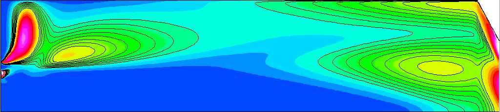
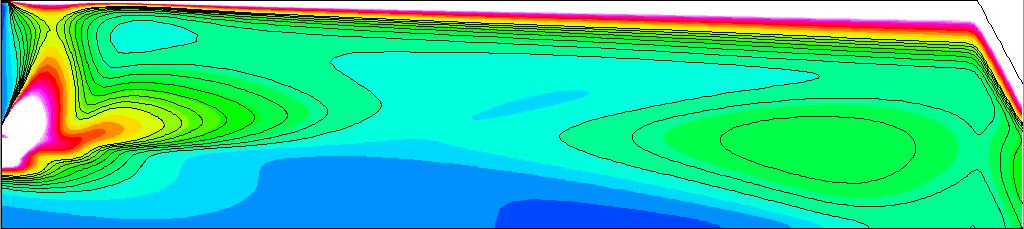
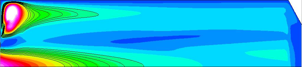
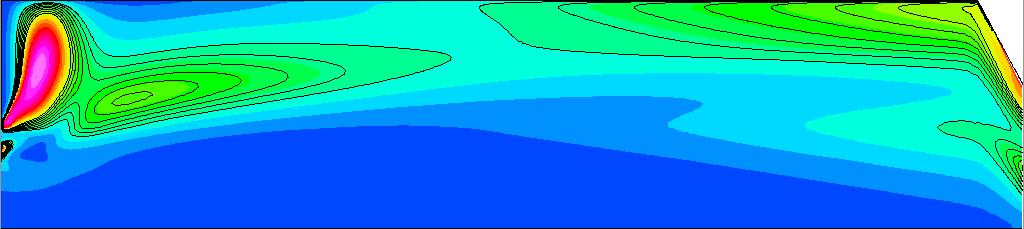
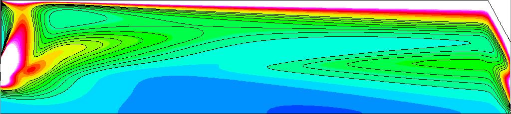
19 1 2 µ t, Pa s 2 4 k, 1 6 m ɛ, s 3 m s ω, s 1 2 r, mm 6 3 (a) TD k-ɛ r, mm 6 3 (b) LFA k-ω-sst r, mm 6 3 (c) JAXA k-ɛ r, mm 6 3 (d) JAXA k-ω-sst r, mm 6 3 (e) IVLR q-ω (ω scaled by 1.9 ) r, mm 6 3 (f) IVLR k-ω-sst r, mm (g) BW k-ω-sst Figure 12. Contour plots of turbulent viscosity (left), turbulent kinetic energy (middle) and turbulent dissipation (right); radial direction scaled by a factor of 1 19 of 2
Numerical Investigation of Flow and Combustion in a Single-Element GCH 4 /GOX Rocket Combustor
 Numerical Investigation of Flow and Combustion in a Single-Element GCH 4 /GOX Rocket Combustor C. Roth, O. Haidn, A. Chemnitz, T. Sattelmayer Technische Universität München, 80333 Munich, Germany Y. Daimon
Steady Laminar Flamelet Modeling for turbulent non-premixed Combustion in LES and RANS Simulations
 Sonderforschungsbereich/Transregio 4 Annual Report 213 139 Steady Laminar Flamelet Modeling for turbulent non-premixed Combustion in LES and RANS Simulations By H. Müller, C. A. Niedermeier, M. Pfitzner
Lecture 9 Laminar Diffusion Flame Configurations
 Lecture 9 Laminar Diffusion Flame Configurations 9.-1 Different Flame Geometries and Single Droplet Burning Solutions for the velocities and the mixture fraction fields for some typical laminar flame configurations.
ADVANCED DES SIMULATIONS OF OXY-GAS BURNER LOCATED INTO MODEL OF REAL MELTING CHAMBER
 ADVANCED DES SIMULATIONS OF OXY-GAS BURNER LOCATED INTO MODEL OF REAL MELTING CHAMBER Ing. Vojtech Betak Ph.D. Aerospace Research and Test Establishment Department of Engines Prague, Czech Republic Abstract
International Journal of Scientific & Engineering Research, Volume 6, Issue 5, May ISSN
 International Journal of Scientific & Engineering Research, Volume 6, Issue 5, May-2015 28 CFD BASED HEAT TRANSFER ANALYSIS OF SOLAR AIR HEATER DUCT PROVIDED WITH ARTIFICIAL ROUGHNESS Vivek Rao, Dr. Ajay
MAE 598 Project #1 Jeremiah Dwight
 MAE 598 Project #1 Jeremiah Dwight OVERVIEW A simple hot water tank, illustrated in Figures 1 through 3 below, consists of a main cylindrical tank and two small side pipes for the inlet and outlet. All
Numerical Simulation of Supersonic Expansion in Conical and Contour Nozzle
 Numerical Simulation of Supersonic Expansion in Conical and Contour Nozzle Madhu B P (1), Vijaya Raghu B (2) 1 M.Tech Scholars, Mechanical Engineering, Maharaja Institute of Technology, Mysore 2 Professor,
A NUMERICAL ANALYSIS OF COMBUSTION PROCESS IN AN AXISYMMETRIC COMBUSTION CHAMBER
 SCIENTIFIC RESEARCH AND EDUCATION IN THE AIR FORCE-AFASES 2016 A NUMERICAL ANALYSIS OF COMBUSTION PROCESS IN AN AXISYMMETRIC COMBUSTION CHAMBER Alexandru DUMITRACHE*, Florin FRUNZULICA ** *Institute of
HEAT TRANSFER IN A RECIRCULATION ZONE AT STEADY-STATE AND OSCILLATING CONDITIONS - THE BACK FACING STEP TEST CASE
 HEAT TRANSFER IN A RECIRCULATION ZONE AT STEADY-STATE AND OSCILLATING CONDITIONS - THE BACK FACING STEP TEST CASE A.K. Pozarlik 1, D. Panara, J.B.W. Kok 1, T.H. van der Meer 1 1 Laboratory of Thermal Engineering,
CFD Simulation of high pressure real gas flows
 CFD Simulation of high pressure real gas flows on the progress form art to physics :o) Maria Magdalena Poschner Prof. Dr. rer. nat. Pfitzner UNIVERSITÄT DER BUNDESWEHR MÜNCHEN Fakultät für Luft und Raumfahrt
NUMERICAL ANALYSIS OF TURBULENT FLAME IN AN ENCLOSED CHAMBER
 NUMERICAL ANALYSIS OF TURBULENT FLAME IN AN ENCLOSED CHAMBER Naveen Kumar D 1*, Pradeep R 2 and Bhaktavatsala H R 3 1 Assistant Professor Department of Mechanical Engineering, M S Engineering College,
ANSYS Advanced Solutions for Gas Turbine Combustion. Gilles Eggenspieler 2011 ANSYS, Inc.
 ANSYS Advanced Solutions for Gas Turbine Combustion Gilles Eggenspieler ANSYS, Inc. 1 Agenda Steady State: New and Existing Capabilities Reduced Order Combustion Models Finite-Rate Chemistry Models Chemistry
CHAPTER 7 NUMERICAL MODELLING OF A SPIRAL HEAT EXCHANGER USING CFD TECHNIQUE
 CHAPTER 7 NUMERICAL MODELLING OF A SPIRAL HEAT EXCHANGER USING CFD TECHNIQUE In this chapter, the governing equations for the proposed numerical model with discretisation methods are presented. Spiral
Lesson 6 Review of fundamentals: Fluid flow
 Lesson 6 Review of fundamentals: Fluid flow The specific objective of this lesson is to conduct a brief review of the fundamentals of fluid flow and present: A general equation for conservation of mass
NUMERICAL AND EXPERIMENTAL INVESTIGATION OF THE TEMPERATURE DISTRIBUTION INSIDE OIL-COOLED TRANSFORMER WINDINGS
 NUMERICAL AND EXPERIMENTAL INVESTIGATION OF THE TEMPERATURE DISTRIBUTION INSIDE OIL-COOLED TRANSFORMER WINDINGS N. Schmidt 1* and S. Tenbohlen 1 and S. Chen 2 and C. Breuer 3 1 University of Stuttgart,
Introduction Flares: safe burning of waste hydrocarbons Oilfields, refinery, LNG Pollutants: NO x, CO 2, CO, unburned hydrocarbons, greenhouse gases G
 School of Process, Environmental and Materials Engineering Computational study of combustion in flares: structure and emission of a jet flame in turbulent cross-flow GERG Academic Network Event Brussels
DEVELOPMENT OF CFD MODEL FOR A SWIRL STABILIZED SPRAY COMBUSTOR
 DRAFT Proceedings of ASME IMECE: International Mechanical Engineering Conference & Exposition Chicago, Illinois Nov. 5-10, 2006 IMECE2006-14867 DEVELOPMENT OF CFD MODEL FOR A SWIRL STABILIZED SPRAY COMBUSTOR
Acoustic Characterization of Virtual Thrust Chamber Demonstrators
 Sonderforschungsbereich/Transregio 4 Annual Report 28 69 Acoustic Characterization of Virtual Thrust Chamber Demonstrators By A. Chemnitz AND T. Sattelmayer Lehrstuhl für Thermodynamik, Technische Universität
DARS overview, IISc Bangalore 18/03/2014
 www.cd-adapco.com CH2O Temperatur e Air C2H4 Air DARS overview, IISc Bangalore 18/03/2014 Outline Introduction Modeling reactions in CFD CFD to DARS Introduction to DARS DARS capabilities and applications
Modeling of Wall Heat Transfer and Flame/Wall Interaction A Flamelet Model with Heat-Loss Effects
 9 th U. S. National Combustion Meeting Organized by the Central States Section of the Combustion Institute May 17-20, 2015 Cincinnati, Ohio Modeling of Wall Heat Transfer and Flame/Wall Interaction A Flamelet
Flow Structure Investigations in a "Tornado" Combustor
 Flow Structure Investigations in a "Tornado" Combustor Igor Matveev Applied Plasma Technologies, Falls Church, Virginia, 46 Serhiy Serbin National University of Shipbuilding, Mikolayiv, Ukraine, 545 Thomas
Numerical Investigation of Ignition Delay in Methane-Air Mixtures using Conditional Moment Closure
 21 st ICDERS July 23-27, 27 Poitiers, France Numerical Investigation of Ignition Delay in Methane-Air Mixtures using Conditional Moment Closure Ahmad S. El Sayed, Cécile B. Devaud Department of Mechanical
Construction of Libraries for Non-Premixed Tabulated Chemistry Combustion Models including Non-Adiabatic Behaviour due to Wall Heat Losses
 Sonderforschungsbereich/Transregio 40 Annual Report 2016 193 Construction of Libraries for Non-Premixed Tabulated Chemistry Combustion Models including Non-Adiabatic Behaviour due to Wall Heat Losses By
Design And Analysis Of Thrust Chamber Of A Cryogenic Rocket Engine S. Senthilkumar 1, Dr. P. Maniiarasan 2,Christy Oomman Jacob 2, T.
 Design And Analysis Of Thrust Chamber Of A Cryogenic Rocket Engine S. Senthilkumar 1, Dr. P. Maniiarasan 2,Christy Oomman Jacob 2, T. Vinitha 2 1 Research Scholar, Department of Mechanical Engineering,
CFD Analysis for Thermal Behavior of Turbulent Channel Flow of Different Geometry of Bottom Plate
 International Journal Of Engineering Research And Development e-issn: 2278-067X, p-issn: 2278-800X, www.ijerd.com Volume 13, Issue 9 (September 2017), PP.12-19 CFD Analysis for Thermal Behavior of Turbulent
Simulation of Turbulent Lifted Flames and their Transient Propagation
 25 th ICDERS August 2-7th, 2015 Leeds, UK Simulation of Turbulent Lifted Flames and their Transient Propagation S. Ruan, Z. Chen, N. Swaminathan University of Cambridge Cambridge, UK 1 Introduction Turbulent
3. FORMS OF GOVERNING EQUATIONS IN CFD
 3. FORMS OF GOVERNING EQUATIONS IN CFD 3.1. Governing and model equations in CFD Fluid flows are governed by the Navier-Stokes equations (N-S), which simpler, inviscid, form is the Euler equations. For
CFD Simulations of Rocket Combustors with Supercritical Injection
 Sonderforschungsbereich/Transregio 40 Annual Report 2016 181 CFD Simulations of Rocket Combustors with Supercritical Injection By M. Seidl, R. Keller AND P. Gerlinger Institut für Verbrennungstechnik der
Consistent turbulence modeling in a hybrid LES/RANS PDF method for non-premixed flames
 Consistent turbulence modeling in a hybrid LES/RANS PDF method for non-premixed flames F. Ferraro, Y. Ge and M. Pfitzner Institut für Thermodynamik, Fakultät für Luft- und Raumfahrrttechnik Universität
Numerical Study of Jet Plume Instability from an Overexpanded Nozzle
 45th AIAA Aerospace Sciences Meeting and Exhibit 8 - January 27, Reno, Nevada AIAA 27-39 Numerical Study of Jet Plume Instability from an Overexpanded Nozzle Q. Xiao * and H.M. Tsai Temasek Laboratories,
LOW TEMPERATURE MODEL FOR PREMIXED METHANE FLAME COMBUSTION
 ISTP-16, 2005, PRAGUE 16TH INTERNATIONAL SYMPOSIUM ON TRANSPORT PHENOMENA LOW TEMPERATURE MODEL FOR PREMIXED METHANE FLAME MBUSTION M. Forman, J.B.W.Kok,M. Jicha Department of Thermodynamics and Environmental
LES/RANS Modeling of Turbulent Mixing in a Jet in Crossflow at Low Velocity Ratios
 LES/RANS Modeling of Turbulent Mixing in a Jet in Crossflow at Low Velocity Ratios Juliane Prause, Yeshaswini Emmi, Berthold Noll and Manfred Aigner German Aerospace Center (DLR), Stuttgart, Germany Turbulent
Fluid Dynamics and Balance Equations for Reacting Flows
 Fluid Dynamics and Balance Equations for Reacting Flows Combustion Summer School 2018 Prof. Dr.-Ing. Heinz Pitsch Balance Equations Basics: equations of continuum mechanics balance equations for mass and
Large Eddy Simulation of Flame Flashback by Combustion Induced Vortex Breakdown
 June 30 - July 3, 2015 Melbourne, Australia 9 1C-5 Large Eddy Simulation of Flame Flashback by Combustion Induced Vortex Breakdown Eike Tangermann Institut für Mathematik und Rechneranwendung Universität
Comparison of Turbulence Models in the Flow over a Backward-Facing Step Priscila Pires Araujo 1, André Luiz Tenório Rezende 2
 Comparison of Turbulence Models in the Flow over a Backward-Facing Step Priscila Pires Araujo 1, André Luiz Tenório Rezende 2 Department of Mechanical and Materials Engineering, Military Engineering Institute,
TAU Extensions for High Enthalpy Flows. Sebastian Karl AS-RF
 TAU Extensions for High Enthalpy Flows Sebastian Karl AS-RF Contents Motivation Extensions available in the current release: Numerical schemes for super- and hypersonic flow fields Models for gas mixtures,
Tutorial: Premixed Flow in a Conical Chamber using the Finite-Rate Chemistry Model
 Tutorial: Premixed Flow in a Conical Chamber using the Finite-Rate Chemistry Model Introduction The purpose of this tutorial is to provide guidelines and recommendations for setting up and solving the
Overview of Turbulent Reacting Flows
 Overview of Turbulent Reacting Flows Outline Various Applications Overview of available reacting flow models LES Latest additions Example Cases Summary Reacting Flows Applications in STAR-CCM+ Ever-Expanding
PDF Modeling and Simulation of Premixed Turbulent Combustion
 Monte Carlo Methods Appl. Vol. No. (), pp. 43 DOI 5 / MCMA.7. c de Gruyter PDF Modeling and Simulation of Premixed Turbulent Combustion Michael Stöllinger and Stefan Heinz Abstract. The use of probability
CFD STUDY OF MASS TRANSFER IN SPACER FILLED MEMBRANE MODULE
 GANIT J. Bangladesh Math. Soc. (ISSN 1606-3694) 31 (2011) 33-41 CFD STUDY OF MASS TRANSFER IN SPACER FILLED MEMBRANE MODULE Sharmina Hussain Department of Mathematics and Natural Science BRAC University,
A Computational Investigation of a Turbulent Flow Over a Backward Facing Step with OpenFOAM
 206 9th International Conference on Developments in esystems Engineering A Computational Investigation of a Turbulent Flow Over a Backward Facing Step with OpenFOAM Hayder Al-Jelawy, Stefan Kaczmarczyk
3D Numerical Simulation of Supercritical Flow in Bends of Channel
 3D Numerical Simulation of Supercritical Flow in Bends of Channel Masoud. Montazeri-Namin, Reyhaneh-Sadat. Ghazanfari-Hashemi, and Mahnaz. Ghaeini- Hessaroeyeh Abstract An attempt has been made to simulate
Simplified Model of WWER-440 Fuel Assembly for ThermoHydraulic Analysis
 1 Portál pre odborné publikovanie ISSN 1338-0087 Simplified Model of WWER-440 Fuel Assembly for ThermoHydraulic Analysis Jakubec Jakub Elektrotechnika 13.02.2013 This work deals with thermo-hydraulic processes
CFD study of gas mixing efficiency and comparisons with experimental data
 17 th European Symposium on Computer Aided Process Engineering ESCAPE17 V. Plesu and P.S. Agachi (Editors) 2007 Elsevier B.V. All rights reserved. 1 CFD study of gas mixing efficiency and comparisons with
NUMERICAL INVESTIGATION ON THE EFFECT OF COOLING WATER SPRAY ON HOT SUPERSONIC JET
 Volume 119 No. 12 2018, 59-63 ISSN: 1314-3395 (on-line version) url: http://www.ijpam.eu ijpam.eu NUMERICAL INVESTIGATION ON THE EFFECT OF COOLING WATER SPRAY ON HOT SUPERSONIC JET Ramprasad T and Jayakumar
DESIGN & COMPUTATIONAL FLUID DYNAMICS ANALYSES OF AN AXISYMMETRIC NOZZLE AT TRANSONIC FREE STREAM CONDITIONS
 DESIGN & COMPUTATIONAL FLUID DYNAMICS ANALYSES OF AN AXISYMMETRIC NOZZLE AT TRANSONIC FREE STREAM CONDITIONS S Wasim Akram 1, S. Rajesh 2 1 M.Tech Student, Department of Mechanical Engineering, Krishna
Numerical investigation on the effect of inlet conditions on the oblique shock system in a high-speed wind tunnel
 American Journal of Physics and Applications 2013; 1(3): 91-98 Published online November 30, 2013 (http:// www.sciencepublishinggroup.com/j/ajpa) doi: 10.11648/j.ajpa.20130103.16 Numerical investigation
Applied Gas Dynamics Flow With Friction and Heat Transfer
 Applied Gas Dynamics Flow With Friction and Heat Transfer Ethirajan Rathakrishnan Applied Gas Dynamics, John Wiley & Sons (Asia) Pte Ltd c 2010 Ethirajan Rathakrishnan 1 / 121 Introduction So far, we have
Turbulent Boundary Layers & Turbulence Models. Lecture 09
 Turbulent Boundary Layers & Turbulence Models Lecture 09 The turbulent boundary layer In turbulent flow, the boundary layer is defined as the thin region on the surface of a body in which viscous effects
Rocket Propulsion Prof. K. Ramamurthi Department of Mechanical Engineering Indian Institute of Technology, Madras
 Rocket Propulsion Prof. K. Ramamurthi Department of Mechanical Engineering Indian Institute of Technology, Madras Lecture 32 Efficiencies due to Mixture Ratio Distribution and Incomplete Vaporization (Refer
CHAPTER 4 OPTIMIZATION OF COEFFICIENT OF LIFT, DRAG AND POWER - AN ITERATIVE APPROACH
 82 CHAPTER 4 OPTIMIZATION OF COEFFICIENT OF LIFT, DRAG AND POWER - AN ITERATIVE APPROACH The coefficient of lift, drag and power for wind turbine rotor is optimized using an iterative approach. The coefficient
Study of the Losses in Fluid Machinery with the Help of Entropy
 Study of the Losses in Fluid Machinery with the Help of Entropy Martin Böhle 1, Annika Fleder 1, Matthias Mohr 1 * SYMPOSIA ON ROTATING MACHINERY ISROMAC 16 International Symposium on Transport Phenomena
TURBINE BURNERS: Engine Performance Improvements; Mixing, Ignition, and Flame-Holding in High Acceleration Flows
 TURBINE BURNERS: Engine Performance Improvements; Mixing, Ignition, and Flame-Holding in High Acceleration Flows Presented by William A. Sirignano Mechanical and Aerospace Engineering University of California
Budget analysis and model-assessment of the flamelet-formulation: Application to a reacting jet-in-cross-flow
 Center for Turbulence Research Proceedings of the Summer Program 212 397 Budget analysis and model-assessment of the flamelet-formulation: Application to a reacting jet-in-cross-flow By W. L. Chan, Y.
7. Basics of Turbulent Flow Figure 1.
 1 7. Basics of Turbulent Flow Whether a flow is laminar or turbulent depends of the relative importance of fluid friction (viscosity) and flow inertia. The ratio of inertial to viscous forces is the Reynolds
Computational Fluid Dynamics Analysis of Jets with Internal Forced Mixers
 Computational Fluid Dynamics Analysis of Jets with Internal Forced Mixers L. A. Garrison A. S. Lyrintzis G. A. Blaisdell Purdue University, West Lafayette, IN, 47907, USA W. N. Dalton Rolls-Royce Corporation,
5. Coupling of Chemical Kinetics & Thermodynamics
 5. Coupling of Chemical Kinetics & Thermodynamics Objectives of this section: Thermodynamics: Initial and final states are considered: - Adiabatic flame temperature - Equilibrium composition of products
THERMAL ANALYSIS OF SECOND STAGE GAS TURBINE ROTOR BLADE
 Polymers Research Journal ISSN: 195-50 Volume 6, Number 01 Nova Science Publishers, Inc. THERMAL ANALYSIS OF SECOND STAGE GAS TURBINE ROTOR BLADE E. Poursaeidi, M. Mohammadi and S. S. Khamesi University
Shock and Expansion Waves
 Chapter For the solution of the Euler equations to represent adequately a given large-reynolds-number flow, we need to consider in general the existence of discontinuity surfaces, across which the fluid
Colloquium FLUID DYNAMICS 2012 Institute of Thermomechanics AS CR, v.v.i., Prague, October 24-26, 2012 p.
 Colloquium FLUID DYNAMICS 212 Institute of Thermomechanics AS CR, v.v.i., Prague, October 24-26, 212 p. ON A COMPARISON OF NUMERICAL SIMULATIONS OF ATMOSPHERIC FLOW OVER COMPLEX TERRAIN T. Bodnár, L. Beneš
Large-eddy simulation of an industrial furnace with a cross-flow-jet combustion system
 Center for Turbulence Research Annual Research Briefs 2007 231 Large-eddy simulation of an industrial furnace with a cross-flow-jet combustion system By L. Wang AND H. Pitsch 1. Motivation and objectives
Process Chemistry Toolbox - Mixing
 Process Chemistry Toolbox - Mixing Industrial diffusion flames are turbulent Laminar Turbulent 3 T s of combustion Time Temperature Turbulence Visualization of Laminar and Turbulent flow http://www.youtube.com/watch?v=kqqtob30jws
The Effect of Endplates on Rectangular Jets of Different Aspect Ratios
 The Effect of Endplates on Rectangular Jets of Different Aspect Ratios M. Alnahhal *, Th. Panidis Laboratory of Applied Thermodynamics, Mechanical Engineering and Aeronautics Department, University of
Lecture 14. Turbulent Combustion. We know what a turbulent flow is, when we see it! it is characterized by disorder, vorticity and mixing.
 Lecture 14 Turbulent Combustion 1 We know what a turbulent flow is, when we see it! it is characterized by disorder, vorticity and mixing. In a fluid flow, turbulence is characterized by fluctuations of
Turbulence Modeling. Cuong Nguyen November 05, The incompressible Navier-Stokes equations in conservation form are u i x i
 Turbulence Modeling Cuong Nguyen November 05, 2005 1 Incompressible Case 1.1 Reynolds-averaged Navier-Stokes equations The incompressible Navier-Stokes equations in conservation form are u i x i = 0 (1)
Numerical Methods in Aerodynamics. Turbulence Modeling. Lecture 5: Turbulence modeling
 Turbulence Modeling Niels N. Sørensen Professor MSO, Ph.D. Department of Civil Engineering, Alborg University & Wind Energy Department, Risø National Laboratory Technical University of Denmark 1 Outline
Computational Investigations of High-Speed Dual-Stream Jets
 9th AIAA/CEAS Aeroacoustics Conference and Exhibit -4 May 3, Hilton Head, South Carolina AIAA 3-33 Computational Investigations of High-Speed Dual-Stream Jets Nicholas J. Georgiadis * National Aeronautics
CHAPTER 7 SEVERAL FORMS OF THE EQUATIONS OF MOTION
 CHAPTER 7 SEVERAL FORMS OF THE EQUATIONS OF MOTION 7.1 THE NAVIER-STOKES EQUATIONS Under the assumption of a Newtonian stress-rate-of-strain constitutive equation and a linear, thermally conductive medium,
AER1310: TURBULENCE MODELLING 1. Introduction to Turbulent Flows C. P. T. Groth c Oxford Dictionary: disturbance, commotion, varying irregularly
 1. Introduction to Turbulent Flows Coverage of this section: Definition of Turbulence Features of Turbulent Flows Numerical Modelling Challenges History of Turbulence Modelling 1 1.1 Definition of Turbulence
Best Practice Guidelines for Combustion Modeling. Raphael David A. Bacchi, ESSS
 Best Practice Guidelines for Combustion Modeling Raphael David A. Bacchi, ESSS PRESENTATION TOPICS Introduction; Combustion Phenomenology; Combustion Modeling; Reaction Mechanism; Radiation; Case Studies;
Lecture 8 Laminar Diffusion Flames: Diffusion Flamelet Theory
 Lecture 8 Laminar Diffusion Flames: Diffusion Flamelet Theory 8.-1 Systems, where fuel and oxidizer enter separately into the combustion chamber. Mixing takes place by convection and diffusion. Only where
Simulation of Aeroelastic System with Aerodynamic Nonlinearity
 Simulation of Aeroelastic System with Aerodynamic Nonlinearity Muhamad Khairil Hafizi Mohd Zorkipli School of Aerospace Engineering, Universiti Sains Malaysia, Penang, MALAYSIA Norizham Abdul Razak School
Theoretical Developments in Group Combustion of Droplets and Sprays
 Theoretical Developments in Group Combustion of Droplets and Sprays William A. Sirignano University of California, Irvine Collaborations: Guang Wu, current student; Randall Imaoka, former student, US Navy;
Computational Fluid Dynamics 2
 Seite 1 Introduction Computational Fluid Dynamics 11.07.2016 Computational Fluid Dynamics 2 Turbulence effects and Particle transport Martin Pietsch Computational Biomechanics Summer Term 2016 Seite 2
Flow characteristics of curved ducts
 Applied and Computational Mechanics 1 (007) 55-64 Flow characteristics of curved ducts P. Rudolf a *, M. Desová a a Faculty of Mechanical Engineering, Brno University of Technology,Technická,616 69 Brno,
Turbulence is a ubiquitous phenomenon in environmental fluid mechanics that dramatically affects flow structure and mixing.
 Turbulence is a ubiquitous phenomenon in environmental fluid mechanics that dramatically affects flow structure and mixing. Thus, it is very important to form both a conceptual understanding and a quantitative
Fluid Dynamics Exercises and questions for the course
 Fluid Dynamics Exercises and questions for the course January 15, 2014 A two dimensional flow field characterised by the following velocity components in polar coordinates is called a free vortex: u r
The effect of geometric parameters on the head loss factor in headers
 Fluid Structure Interaction V 355 The effect of geometric parameters on the head loss factor in headers A. Mansourpour & S. Shayamehr Mechanical Engineering Department, Azad University of Karaj, Iran Abstract
SIMULATION AND ASSESSMENT OF AIR IMPINGEMENT COOLING ON SQUARED PIN-FIN HEAT SINKS APPLIED IN PERSONAL COMPUTERS
 20 Journal of Marine Science and Technology, Vol. 13, No. 1, pp. 20-27 (2005) SIMULATION AND ASSESSMENT OF AIR IMPINGEMENT COOLING ON SQUARED PIN-FIN HEAT SINKS APPLIED IN PERSONAL COMPUTERS Hwa-Chong
Shape Optimisation of Axisymmetric Scramjets
 Shape Optimisation of Axisymmetric Scramjets Hideaki Ogawa 11 th International Workshop on Shock Tube Technology Australian Hypersonics Workshop 2011 University of Queensland, Brisbane 23 rd March 2011
TOPICAL PROBLEMS OF FLUID MECHANICS 97
 TOPICAL PROBLEMS OF FLUID MECHANICS 97 DOI: http://dx.doi.org/10.14311/tpfm.2016.014 DESIGN OF COMBUSTION CHAMBER FOR FLAME FRONT VISUALISATION AND FIRST NUMERICAL SIMULATION J. Kouba, J. Novotný, J. Nožička
COMPUTATIONAL FLUID DYNAMICS ANALYSIS OF A V-RIB WITH GAP ROUGHENED SOLAR AIR HEATER
 THERMAL SCIENCE: Year 2018, Vol. 22, No. 2, pp. 963-972 963 COMPUTATIONAL FLUID DYNAMICS ANALYSIS OF A V-RIB WITH GAP ROUGHENED SOLAR AIR HEATER by Jitesh RANA, Anshuman SILORI, Rajesh MAITHANI *, and
7.2 Sublimation. The following assumptions are made in order to solve the problem: Sublimation Over a Flat Plate in a Parallel Flow
 7..1 Sublimation Over a Flat Plate in a Parallel Flow The following assumptions are made in order to solve the problem: 1.. 3. The flat plate is very thin and so the thermal resistance along the flat plate
On the transient modelling of impinging jets heat transfer. A practical approach
 Turbulence, Heat and Mass Transfer 7 2012 Begell House, Inc. On the transient modelling of impinging jets heat transfer. A practical approach M. Bovo 1,2 and L. Davidson 1 1 Dept. of Applied Mechanics,
PDF modeling and simulation of premixed turbulent combustion
 Monte Carlo Methods Appl. Vol. 4 No. 4 (8), pp. 343 377 DOI. / MCMA.8.6 c de Gruyter 8 PDF modeling and simulation of premixed turbulent combustion Michael Stöllinger and Stefan Heinz Abstract. The use
Laminar Premixed Flames: Flame Structure
 Laminar Premixed Flames: Flame Structure Combustion Summer School 2018 Prof. Dr.-Ing. Heinz Pitsch Course Overview Part I: Fundamentals and Laminar Flames Introduction Fundamentals and mass balances of
ENTROPY PRODUCTION MODELING IN CFD OF TURBULENT COMBUSTION FLOW
 ENTROPY PRODUCTION MODELING IN CFD OF TURBULENT COMBUSTION FLOW Ivar S. Ertesvåg, Jostein Kolbu Department of Energy and Process Engineering Norwegian University of Science and Technology NO-7491 Trondheim,
ENGINEERING MECHANICS 2012 pp Svratka, Czech Republic, May 14 17, 2012 Paper #195
 . 18 m 2012 th International Conference ENGINEERING MECHANICS 2012 pp. 309 315 Svratka, Czech Republic, May 14 17, 2012 Paper #195 NUMERICAL SIMULATION OF TRANSITIONAL FLOWS WITH LAMINAR KINETIC ENERGY
Manhar Dhanak Florida Atlantic University Graduate Student: Zaqie Reza
 REPRESENTING PRESENCE OF SUBSURFACE CURRENT TURBINES IN OCEAN MODELS Manhar Dhanak Florida Atlantic University Graduate Student: Zaqie Reza 1 Momentum Equations 2 Effect of inclusion of Coriolis force
Heat and Mass Transfer Prof. S.P. Sukhatme Department of Mechanical Engineering Indian Institute of Technology, Bombay
 Heat and Mass Transfer Prof. S.P. Sukhatme Department of Mechanical Engineering Indian Institute of Technology, Bombay Lecture No. 18 Forced Convection-1 Welcome. We now begin our study of forced convection
Soot formation in turbulent non premixed flames
 Soot formation in turbulent non premixed flames A. Cuoci 1, A. Frassoldati 1, D. Patriarca 1, T. Faravelli 1, E. Ranzi 1, H. Bockhorn 2 1 Dipartimento di Chimica, Materiali e Ing. Chimica, Politecnico
Carbon Science and Technology
 ASI RESEARCH ARTICLE Carbon Science and Technology Received:10/03/2016, Accepted:15/04/2016 ------------------------------------------------------------------------------------------------------------------------------
Transport equation cavitation models in an unstructured flow solver. Kilian Claramunt, Charles Hirsch
 Transport equation cavitation models in an unstructured flow solver Kilian Claramunt, Charles Hirsch SHF Conference on hydraulic machines and cavitation / air in water pipes June 5-6, 2013, Grenoble, France
LES of the Sandia Flame D Using an FPV Combustion Model
 Available online at www.sciencedirect.com ScienceDirect Energy Procedia 82 (2015 ) 402 409 ATI 2015-70th Conference of the ATI Engineering Association LES of the Sandia Flame D Using an FPV Combustion
CHARACTERISTICS OF ELLIPTIC CO-AXIAL JETS
 ELECTRIC POWER 2003 March 4-6, 2003 George R Brown Convention Center, Houston, TX EP 03 Session 07C: Fuels, Combustion and Advanced Cycles - Part II ASME - FACT Division CHARACTERISTICS OF ELLIPTIC CO-AXIAL
NPC Abstract
 NPC-2013-15002 Development of Mach 3.6 water cooled Facility Nozzle By Jayaprakash C*, Sathiyamoorthy K*, Ashfaque A. Khan*, Venu G*, Venkat S Iyengar*, Srinivas J**, Pratheesh Kumar P** and Manjunath
WALL ROUGHNESS EFFECTS ON SHOCK BOUNDARY LAYER INTERACTION FLOWS
 ISSN (Online) : 2319-8753 ISSN (Print) : 2347-6710 International Journal of Innovative Research in Science, Engineering and Technology An ISO 3297: 2007 Certified Organization, Volume 2, Special Issue
EVALUATION OF FOUR TURBULENCE MODELS IN THE INTERACTION OF MULTI BURNERS SWIRLING FLOWS
 EVALUATION OF FOUR TURBULENCE MODELS IN THE INTERACTION OF MULTI BURNERS SWIRLING FLOWS A Aroussi, S Kucukgokoglan, S.J.Pickering, M.Menacer School of Mechanical, Materials, Manufacturing Engineering and
GPPS NUMERICAL PREDICTION OF UNSTEADY ENDWALL FLOW AND HEAT TRANSFER WITH ONCOMING WAKE
 Proceedings of Shanghai 17 Global Power and Propulsion Forum 3 th October 1 st November, 17 http://www.gpps.global GPPS-17-133 NUMERICAL PREDICTION OF UNSTEADY ENDWALL FLOW AND HEAT TRANSFER WITH ONCOMING
Modeling of Humidification in Comsol Multiphysics 4.4
 Modeling of Humidification in Comsol Multiphysics 4.4 Indrajit Wadgaonkar *1 and Suresh Arikapudi 1 1 Tata Motors Ltd. Pimpri, Pune, India, 411018. *Corresponding author: Indrajit Wadgaonkar, Tata Motors