Unified Direct-Flux Vector Control for AC Motor Drives
|
|
|
- Leslie Gibson
- 5 years ago
- Views:
Transcription
1 Unified Direct-Flux Vector Control for AC Motor Drives G. Pellegrino Member, IEEE R. Bojoi Senior Member, IEEE P. Guglielmi Member, IEEE Politecnico di Torino, Corso Duca degli Abruzzi 4, Torino, 1019 Italy Abstract -- The paper introduces a Unified Direct-Flux Vector Control scheme suitable for sinusoidal AC motor drives. The AC drives considered here are Induction Motor, Synchronous Reluctance and synchronous Permanent Magnet motor drives, including Interior and Surface-mounted Permanent Magnet types. The proposed controller operates in stator flux coordinates: the stator flux amplitude is directly controlled by the direct voltage component, while the torque is controlled by regulating the quadrature current component. The unified directflux control is particularly convenient when fluxweakening is required, since it easily guarantees maximum torque production under current and voltage limitations. The hardware for control is standard and the control firmware is the same for all the motors under test with the only exception of the magnetic model used for flux estimation at low speed. Experimental results on four different drives are provided, showing the validity of the proposed unified control approach. Index Terms -- Variable Speed Drives, Synchronous Motor Drives, Permanent magnet machines, Traction Motor Drives, Motion Control, Flux-weakening, imited Voltage Control. I. INTRODUCTION The concept of a unified control scheme to be used with different AC motors is known from more than one decade: industrial controllers are available on the market [1] and unified vector control schemes have been proposed in the literature for Induction Motor (IM) and Surface-mounted Permanet Magnet (SPM) motor drives []. The general approach called active-flux proposed in [3] covered IM and SPM as well as Interior Permanent-Magnet (IPM), Synchronous Reluctance (SyR) and wound rotor synchronous motors. All the cited schemes [1-3] use rotor flux orientation and current vector control. A different approach, based on direct flux, direct torque control has been also proposed as UNIDRIVE in [4]. The goal of the paper is to propose a control strategy with high degree of generality to be used either with IM, IPM, SPM and SyR motor drives. Respect to other unified solutions based on rotor flux (or active flux) orientation, the proposed Unified Direct-Flux Vector Control (UDFVC) scheme uses a Direct Stator Flux Control (DSFC) approach implemented in the stator flux reference frame. The stator flux is directly controlled by the d-axis component of the stator voltage vector, while the torque is controlled by regulating the q-axis component of the stator current vector. The direct flux control makes the proposed UDFVC very effective in terms of voltage utilization in the flux-weakening region, that is particularly used in traction, spindle drives and home appliances. For all the motor types the inverter voltage and current limits are fully exploited in flux-weakening with no need of knowledge of the motor model (except for the stator resistance), even in the case of a variable DC link voltage [5-6]. The motor magnetic model (or current model) is used for flux estimation at low speed as for most IM field-oriented control schemes [7] and as it is also usual for position sensorless control techniques [8]. Eventual parameter errors can lead to a flux estimation error in the low speed region, and to a possible steady-state torque estimation error. However, the control is robust in all the speed range and its dynamic response is independent of the model errors. In this paper, only sensored operation is addressed, i.e. the rotor position is measured by means of a position sensor. However, the unified control can be easily extended to sensorless applications, as already shown for the IM [6]. Experimental results are presented for IM, IPM, SPM and SyR machines, showing the feasibility of the proposed control, and in particular the robust flux-weakening operation. II. AC MACHINES MODEING As a general notation, the machine stator vectors (voltage, flux, current) will be called v, and i respectively, and the subscript s will refer to the stator flux reference frame when associated to those variables. The adopted vector reference frames are defined in Fig. 1, for all the considered machines: stationary frame (α,β), rotor frame (d m,q m ), rotor flux frame (d,q) and stator flux frame (d s,q s ). For convenience, the axis alignment chosen for the SyR motor (Fig. 1-d) is unconventional, with the d-axis along the minimum permeance direction instead of the maximum permeance one as more usual in the literature. This choice permits to adopt unified magnetic equations for the three synchronous machines (SyR, IPM, SPM), as clarified in the following.
2 q s q s β q (a) IM β d s δ d ϑ,ω r d m ϑ m,ω m ω α d s q=q m δ d=d m ϑ=ϑ m ω=ω m α q s q s q=q m β d s (b) SPM β δ d=d m d s q=q m δ ϑ=ϑ m ω=ω m α d=d m ϑ=ϑ m ω=ω m α has an effect only at very low speed. To get an accurate torque estimation around zero speed, the magnetic model should be accurate and implemented in the form of - dimensional look-up tables d (i d, i q ) and q (i d, i q ) as suggested in [10], otherwise simplified models are working well. B. IM magnetic model The current to flux relationship for the IM is (4), where the rotor flux can be derived from the rotor equation (5) [7]. = k + σ i (4) r dr,dqm τ r + r,dqm = m idqm (5) dt where σ is the leakage factor, s is the stator inductance, τ r = r /R r is the rotor time constant and k r = m / r is the rotor coupling factor. As said, the rotor reference frame (d m,q m ) has been adopted in (5). r s (c) IPM (d) SyR Figure 1. Definiton of common reference frames for all AC machines. Independently of the adopted reference frame (stationary, rotor flux, stator flux), all the considered AC machines have the same voltage model and torque expressions. For example, in the rotor synchronous frame we get: v dq ddq = Rs idq + + jωdq (1) dt 3 T = p ( i i ) d q q d where R s is the stator resistance, ω is the synchronous speed and p is the number of pole-pairs. Each machine has its own specific current-to-flux vector relationship: in the following subsections, the magnetic models of the considered motors will be briefly summarized, expressed in the rotor mechanical frame (d m,q m ) that coincides with the rotor synchronous frame (d,q) for all the synchronous machines. The reason of this choice will be better clarified in the Stator flux observer subsection (IV.A). A. IPM, SyR and SPM motor magnetic models The simplified IPM magnetic model in rotor coordinates can be expressed as dq d = 0 0 m dq i q + 0 where d and q are the d-axis and q-axis inductances and m is the PM linked flux or no-load flux linkage. The model of an isotropic SPM motor is also represented by (3), with d = q = s, while the model of a SyR motor is (3) with m = 0. A more realistic model should account for magnetic saturation and cross-saturation [9], in particular for IPM and SyR motors. As shown in the following, the model accuracy () (3) III. UNIFIED DIRECT-FUX VECTOR CONTRO IN STATOR FUX COORDINATES The voltage model (6) and torque equation (7) are common to all the machines also in the stator flux frame as v dqs = R d 0 i + + dδ dqs dt ω+ 0 dt 3 T = p s where δ is the load angle, i.e. the phase angle of the stator flux with respect to the rotor flux (IM) or with respect to the d-axis (SyR, SPM, IPM). From (6) it results that the stator flux amplitude can be regulated by means of the d s -axis voltage and the load angle (i.e. torque) by means of the q s -axis voltage. However, the unified torque expression (7) suggests that the control of the q s -axis current instead of the load angle may lead to a simple and unified torque control scheme [5-6]. For this reason, a further manipulation of the quadrature state equation in (6) is necessary for all the machines. A. Quadrature current equation for IPM, SyR and SPM As described in [5], the q s -axis current equation for an IPM motor is diqs R i + k v R i + b v ω (8) d i qs ( ) ( ) = s qs ds s ds qs dt where the two factors k and b are defined in (9) for the IPM, in (10) for the SyR and in (11) for the SPM. k b IPM IPM ( δ ) = 1 d 1 sin( δ) ( δ ) = d m, 1 cos( δ) + cos( δ) q q (6) (7) (9)
3 For the SyR motor the k factor is the same of (9), while the b factor is obtained by posing m equal to zero: ( δ) = k ( δ) k SyR IPM ( ) (10) δ = d b SyR, 1 cos( δ) q The SPM motor has k equal to zero and a simplified expression of b: k SPM = 0 (11) m bspm (, δ) = cos( δ) It must be underlined that the b factor is representative of the torque derivative with respect to the load angle δ, as addressed in [5]. d T b = (1) δ = const The effects of b in flux-weakening operation, and in particular the relationship between b and the Maximum Torque per Voltage (MTPV) operation will be put in evidence in the following (III.C III.E). B. Quadrature current equation for IM As shown in [6], the q s -axis current equation for an IM is: diqs σ s = Req iqs ωslip σs ids + ( vqs ωm ) (13) dt where R eq = R s + k r /k s R r and ω slip is the slip speed defined as ω slip = ω - ω m. C. Direct flux vector control From the machine models (6-13), it follows that: a) The stator flux regulation by means of the d s voltage is decoupled from the q s axis and leads to a closed-loop bandwidth that is directly imposed by the proportional gain of a proportional-integral (PI) flux controller with no influence of magnetic saturation. b) The torque can be regulated by controlling the q s current component via the q s -axis voltage using a PI current controller. The bandwidth of the q s -axis current loop is imposed by the proportional gain of the PI current controller and the inductance q (IPM and SyR), σ s (IM) or s (SPM). c) For all motors save the SPM (that has k SPM = 0) the control of i qs (torque) is dynamically coupled with the flux control axis. This is usual with Stator Field Oriented Control (SFOC) of IMs. The advantages and disadvantages of SFOC with respect to rotor field oriented control have been comprehensively analyzed for IM [11], showing that the torque dynamics can be made comparable with proper compensation [1]. It must be also considered that IPM and SyR motors would have shown a d-q coupling also if the rotor reference frame was adopted, since both (d,q) current components give torque contributions. d) All the synchronous motors (SPM, IPM, SyR) have to cope with the variable b term in (8). Once the bandwidth of q s -axis current regulation is imposed by a proper design of PI current controller, the torque response depends on the b value. This means that: 1) at rated torque (low speed and rated flux and load angle) the torque response is very fast, being similar with the torque response obtained by currentcontrolled AC drives using (d,q) rotor flux frame and ) at high speed (during flux-weakening) the torque response can become slower since b is reduced, but it is unlikely that step torque disturbances are applied at such high speeds. e) For IPM and SyR motors, the coupling of the i qs equation with the direct axis, i.e. the effect of the v ds voltage component on the i qs dynamics depends on the term k(δ) in (9) and (10) respectively and is visible during flux regulation transients only (at steady state v ds = R s i ds ). The closed-loop control of i qs rejects the effects of such moderate crosscoupling. Model-based compensation is also possible in case of severe dynamics requirements. f) For IMs, equation (13) shows two coupling terms, i.e. ω m and σ s ω slip i ds. Both terms can be estimated and compensated in a feedforward fashion. The first term is not critical for torque dynamics since it is slowly varying during flux regulation or speed variations. The second term requires the estimation of the slip speed, as in [1]. g) The (, i qs ) control is stable for torque values under the pull-out torque limit, also called maximum torque per flux or Maximum Torque per Voltage (MTPV) limit. This is particularly evident from (8, 9) for the synchronous machines. The i qs control loop is stable if b(,δ)>0, while it becomes unstable if b < 0, according to (8). It will be shown in the following that the b = 0 boundary coincides with the MTPV trajectory. MTPV operation is achieved in the proposed control by limiting the flux phase angle δ to be under a proper maximum value that is typical of each motor type. D. Maximum torque per voltage operation The MTPV operation occurs in the flux-weakening region at high speed and it is also called voltage limited operation [13]. Given the voltage limit, over a certain speed it is no longer convenient to exploit the full inverter current I max for obtaining the maximum machine torque, because the pull-out torque limit has been reached. The pull-out torque condition coincides with a specific value of the load angle δ. Such value will be indicated as δ max from now on and varies with the motor type. Below the pull-out limit the flux phase angle is δ < δ max. The expression of δ max for the considered motors is obtained by expressing the electromagnetic torque () as a function of the flux amplitude and phase, and then posing to zero the torque partial derivative with respect to δ, that is at constant flux amplitude. E. Pull out torque angle of IPM, SyR and SPM motors The manipulation of () and (3) leads to
4 3 p q d sin δ T = + sin δ m (14) d q The torque derivative with respect to δ is T 3 p q d = cos δ + cos δ δ m (15) d q By imposing (15) to be equal to zero, the MTPV load angle condition is obtained as q d cos δ = m cos δ (16) q For the SyR and SPM motors, eq. (16) has an easy solution. In particular, for SyR motor the right side of (16) is zero ( m = 0) and leads to δmax,syr = 135 (17) For SPM the left side of (16) is zero ( d = q ), i.e. δmax,spm = 90 (18) A comment is needed about the SyR motor. The value 135 has been obtained here because of the particular choice of the reference axes, introduced in Fig. 1 and commented in section II. With the adopted axes, the motoring operation of the SyR machine is in the second quadrant of the dq plane, thus the 135 value is the corrected value to be considered. With standard (d,q) axes the more familiar solution δ max = 45 (first quadrant) would have been obtained for motoring. Dealing with the IPM motor, the solution of (16) depends of the relationship between the motor saliency, represented by the ( q d )/ q term, and the PM flux, both being dependent on the motor design. In any case, the solution of (16) leads to a δ max that is an intermediate value between the values given in (17) and (18): 90 < δmax, IPM < 135 (19) For IPM motors with high saliency, the value approaches 135 as for a SyR motor, while it moves towards 90 for low saliency motors, as for an SPM motor. According to the definition of b given by (1), the condition b = 0 coincides with the MTPV operation. As said, the i qs control would become instable in case of b < 0, thus the correct exploitation of the MTPV control trajectory maintains the proposed control stable over the whole speed range, as it will be shown in sections IV and V. F. Pull out torque angle of the IM In rotor flux coordinates, the substitution of r = m i d in (4) leads to s 0 dq = idq 0 σ s From () and (0) the torque expression becomes 3 1 σ sin T = p δ σ s (0) (1) The torque derivative with respect to δ is T σ = 3 1 p δ δ σ cos () s The MTPV load angle is obtained when () is zero, i.e. δmax = 45 (3), IM IV. UDFVC IMPEMENTATION The proposed UDFVC control scheme is shown in Fig. for a speed-controlled AC drive. The flux and quadrature current references ( *, i qs * ) are computed from the torque reference using (7). The flux set-point at low speed can be either a constant value (e.g. for IM and SyR drives) or a function of the torque set-point. In Fig. the Maximum Torque per Ampere (MTPA) law has been chosen, but simpler functions are possible with no significant side-effects [5]. The main blocks of Fig. are discussed in the following subsections. A. Stator flux observer The unified stator flux observer (Fig. 3) is based on the current-to-flux model at low speed and on back-emf integration at high speed [7,14]. The magnetic model is represented for all the machines in the (d m,q m ) rotor frame (see Section II). In general terms, such scheme can be indicated as a reduced-order VIθ m closed-loop observer. The crossover angular frequency ω co between low-speed and high speed models coincides with the observer gain g (rad/s). As said, for synchronous machines the simple magnetic model (3) or more accurate models can be adopted. For IM drives the model is (5) and it is affected, as usual, by the uncertainty on the parameters m and τ r. In case of an inaccurate model, the obtained torque differs from the torque set point but the control is still stable. In other words, the motor parameter inaccuracies or variations affect only the drive performance at low-speed and not the high-speed operation, as it happens with pure current vector control where the flux weakening trajectories are based on the model. The observer outputs needed for control are evidenced in Fig. 3. In particular, the sine and cosine of the flux phase angle θ + δ are obtained dividing the α, β flux components by the flux amplitude. Moreover, the sine and cosine of the load angle δ are obtained by a further coordinate rotation: the angle θ coincides with θ m for the synchronous machines, while for the IM case it is the phase angle of the rotor flux vector (Fig. 1a) and its sine and cosine (needed for the coordinate rotation of Fig. 3) are estimated using (4) for rotor flux estimation. In those applications where very low speed operation is not required and/or the starting torque is moderate, the magnetic model feedback can even become unnecessary.
5 Figure. Unified direct-flux vector control scheme. The observer scheme of Fig. 3 can be simplified in the form of a simple stator flux estimator with ow-pass Filter (PF), where the gain g is the PF pole [15]. Gain and phase compensation may be required, depending on g value and the minimum electrical speed ω. Figure 3. Unified VIθ m flux observer. The the angle θ is θ m for the synchronous motors whilst it is the rotor flux position for the IM, estimated by means of (4) applied to the observed stator flux. B. Vector control The vector control block in Fig. contains the flux and quadrature current regulators that give the voltage reference in stator flux coordinates. The flux and current controllers are simple PI regulators and the firmware is the same for all the motors. The bandwidth of the control is independent of magnetic saturation and machine model, thus the settings of the PI flux regulator are the same for all the motors. The i qs control loop, according to (8), has disturbance terms. The term ω m is feed-forward compensated in all the motors, while the other terms are compensated by the integrative action of the current controller. C. Maximum voltage limitation The maximum voltage limit is respected by limiting the flux reference according to the synchronous speed and the actual DC link voltage (4). * [ V R i sign( ω) ] ω (4) max s where V max is the inverter maximum voltage that is updated according to the measured DC link voltage [5-6]. The setting of V max determines whether the inverter overmodulation region is exploited or not. A typical setting uses V max = v dc / 3, where v dc is the measured DC link voltage. The resistive term in (4) is used only for low power motors, otherwise it can be neglected. D. Maximum current limitation The motor phase current is limited by saturating the quadrature current reference according to (5), where I max is the inverter maximum current. qs * i qs Imax ids (5) E. Maximum torque per voltage (MTPV) current limitation As introduced in III.D-III.F, the MTPV operation can be obtained by limiting the load angle to be under δ max, that depends of the motor type. There is a tight relationship between the i qs current component and the load angle δ. In particular, the limitation of the i qs current produces a limitation of the load angle. For this reason, the MTPV operation is obtained by limiting the i qs current reference, according to the observed load angle. While the just described I max saturation keeps the current inside the inverter limit, this further i qs limitation is performed by the same saturation block (see Fig. ) and represented by the current component i MTPV. This component, subtracted from the I max limit (5), leads to a reduction of the current amplitude below the inverter maximum rating ( i < I max ), as
6 requested under the pull-out torque conditions. The δ max angle limits have been calculated in (17-19) and (3). Dealing with the IPM case (19), the exact value depends on the motor and can be evaluated by model manipulation or by dedicated tests at no-load with trial and error values in the range (19). The unified calculation of the MTPV-limiting current component i MTPV based on a PI controller, as shown in Fig., whose output is non zero only in case the estimated load angle overcomes the set point δ max. The unified estimation of the load angle error (δ δ max ), that is the input of the PI regulator, requires a specific implementation. First of all, the sine and cosine components of the load angle are obtained by coordinate rotation as indicated in Fig. 3. Then, two solutions are possible: to evaluate δ as the arc tangent of its sine divided by cosine, or, to avoid the division, to evaluate δ δ max as the cross product between the sine and cosine components of the respective angles. The tuning of the PI regulator gains and the bandwidth of the δ max limitation can be evaluated according to the simplified block scheme of Fig. 4. The inverter and flux observer dynamics have been neglected. The closed loop bandwidth of the δ max limitation is: k p, δ k p,iqs ωb, δ = (6) Where k p,δ and k p,iqs are the proportional gains of the δ max and i qs regulators respectively. The bandwidth depends on the flux amplitude and must be set according to its minimum value that is at maximum speed. It can be demonstrated that the PI-based δ max control overcomes the instability problems of (, i qs ) control with any δ max set-point, properly or improperly selected. Figure 4. Dynamic block scheme representing δ max regulation. V. EXPERIMENTA RESUTS Experimental tests have been carried out on four different machines (IM, IPM, SPM, SyR), whose characteristics are reported in the Appendix. A. Experimental setup The IM, IPM and SyR have similar size and operating speed, according to their common application field that is home appliances. In particular, the SyR motor is derived from an IPM prototype for home appliances, assembled with no magnets for research purposes and performance comparison. Thus the SyR has a limited constant power speed range and operating speed range ( rpm), with respect to the IM and IPM ones ( rpm). The SPM motor is of a larger size, larger current and has a maximum speed of 6000 rpm. Two different experimental rigs have been used for the tests. For the small size motors (IM, IPM and SyR) the inverter is rated 10A (pk) output current, with 0V/50Hz single phase AC input and passive rectifier. The controller is a dspace DS1103 PPC board. For the SPM motor an inverter of larger size has been used, controlled by a floatingpoint micro controller (ADSP 1060). The current limit is 0A in this case that is nearly half of the motor characteristic current and corresponds to a maximum speed of 6000 rpm that is the motor rating due to centrifugal constraints. The three phase currents and the dc-link voltage and rotor position are measured at a sampling frequency of 10 khz that is also the PWM switching frequency. The position is measured by a standard incremental encoder with 51 pulses per revolution. B. Speed reversals with deep flux-weakening operation Results for step speed reversal are shown in Figs. 4-7 for the four machines. The reported signals are the measured speed, the controlled variables (, i qs ), one phase current and the estimated load angle. The IM speed reversal (±16000 rpm) is shown in Fig. 5: the inverter current limit is set to 8 A pk. In the low speed range (0.1s to 0.4 s), the phase currents are clamped to 8 A by the current limitation block. At high speed, the current amplitude is reduced by the MTPV i qs saturation block. The deceleration ( rpm) is faster than the acceleration for two reasons: (a) the motor losses (iron, copper) help braking; (b) the available voltage is higher (the regeneration charges the DC link capacitor up to the trip level of a braking resistor) and a higher flux reference is set, according to (4), from which the higher torque. The noise on i qs during acceleration (Fig. 5) is due to the 100 Hz dc-link voltage ripple since the inverter is fed by a single-phase diode rectifier with 50Hz ac supply. In Fig. 6, the speed reversal of the IPM motor has similar characteristics. The maximum current is set to 5 A pk. For most of the time the phase current amplitude is less than 5A to the MTPV limitation, while maximum current operation is evidenced at low speed (< 4000rpm). The SyR motor speed reversal (± 6000 rpm) is shown in Fig. 7 with the current limit set to 5A pk. The motor torque is heavily MTPV limited above 4000 rpm (positive or negative) and results in a very limited speed range in flux weakening. However, the limited speed range in flux weakening is a characteristic of the SyR motor type and not a limitation imposed by the control. The SPM motor speed reversal (± 6000 rpm) is shown in Fig. 8 using two different ramps. The inverter current limit has been set at 0A pk. The fast ramp (top) shows that the current needed for de-magnetization at 6000rpm, no-load, is much higher than the i qs current needed for fast acceleration (10A).
. Figure 8.")
 and 0000rpm/s (bottom). Figure 6.")

7 Figure 5. IM speed reversal ( 16000rpm 16000rpm). Figure 7. SyR motor speed reversal ( 6000rpm 6000rpm). Figure 8. SPM motor speed reversal ( 6000rpm 6000rpm) with two different ramp slopes: 10000rpm/s (top) and 0000rpm/s (bottom). Figure 6. IPM motor speed reversal ( 16000rpm 16000rpm). C. MTPV operation The trajectories of the flux vector in the dq rotor flux reference frame are shown for the IM, IPM and SyR cases, during the speed reversals described in the previous
8 subsection. The SPM motor has a limited flux weakening capability at rated current and has not been tested in MTPV operation, that would have required an 50% overload (i.e. a current greater than the characteristic current see Table I). The flux trajectory of the IM motor is shown In Fig. 9, using an MTPV limitation at δ max = 45. The red and blue traces are superimposed and represent the deceleration and acceleration paths, respectively. As said, the noise in acceleration is due to the dc-link voltage ripple, since the flux amplitude reference is limited according to the current value of the dc-link, filtered by a first order low-pass filter with cut-off frequency of 5 Hz. In Fig. 10-a the trajectories for the IPM motor have a poor quality due to the signals downsampling during the duration of the speed transient (.5 s). The load angle is limited at δ max = 16 since the motor under test has a high saliency and a low per-unit PM flux. In Fig. 10-b the trajectories for the SyR motor reveal the poor flux weakening capability of the drive (the rated flux is not so far from the MTPV angle). The load angle is limited at δ max = 135. Figure 9. Trajectory of the IM observed flux in the during the speed reversal of Fig. 5. d and q are the observed rotor flux axes. (a) Figure 10. Trajectories of the observed flux in the during the speed reversals. a) IPM motor, refer to Fig. 6; b) SyR motor, refer to Fig. 7. d and q are the rotor axes given by the encoder. (b) D. ow speed operation The load step response at low speed is presented for the IM and IPM motor cases in Figs. 11 and 1 respectively. Both the motor drives are speed controlled at 0 rpm and loaded by means of a torque-controlled DC motor. In both cases a.0 Nm torque step is applied and released, starting from and returning to no load conditions. The load step is within the current saturation limit in both cases. The speed responses are similar, in terms of peak transient speed error. With reference to the observed flux subplots, the IM flux reference (Fig. 11) is constant, independent of the reference torque, while the IPM motor flux reference is varied according to the torque set-point (Fig. 1). The low frequency component superimposed to i qs in both tests is due to a torque disturbance introduced by the DC motor that depends on the mechanical speed. VI. CONCUSIONS The proposed unified direct-flux vector control consists of a common control firmware that applies to four sinusoidal AC motor types. The only implementation difference is the motor model used in the stator flux observer for low-speed operation. Simplified or detuned motor models can produce steady-state torque estimation at low speed but no worse sideeffects. The current and voltage limits are fully exploited by limiting the flux and torque current references with simple control laws that are independent of the motor parameters and valid also in case of a variable DC link. The control algorithm requires three PI regulators: two are for flux and i qs current control and one is for load angle limitation at high speed. The proposed scheme combines the advantages of the direct flux control along with only one current regulation channel for the torque-producing current component. In this way, both the flux-weakening and the current limitation are straightforward and easy to implement. The flux-current control is stable at high speed if the load angle limitation is used. Experimental results have been presented for all motors for heavy speed transients, demonstrating the feasibility of the proposed solutions. REFERENCES [1] The control techniques drives and controls handbook, W. Drury (Ed.), 001. ISBN: & []. Harnefors, M. Jansson, R. Ottersen and K. Pietiläinen, Unified Sensorless Vector Control of Synchronous and Induction Motors, IEEE Trans. Ind. Electron.,vol.50, No.1, February 003, pp [3] I. Boldea, M.C. Paicu and Gh.-D. Andreescu, Active Flux Concept for Motion-Sensorless Unified AC Drives, IEEE Trans. Power Electron., Vol.3, No.5, September 008, pp [4] C. ascu, I. Boldea and F. Blaabjerg, "The Torque Vector Controlled (TVC) Universal AC Drive, Implementation Aspects, Conf. Rec. IEEE OPTIM 1998, vol., pp , [5] G. Pellegrino, E. Armando and P. Guglielmi, Direct Flux Field- Oriented Control of IPM drives with variable DC link in the Field- Weakening Region, IEEE Trans. Ind. Appl., Vol 45, Issue, September/October 009, pp


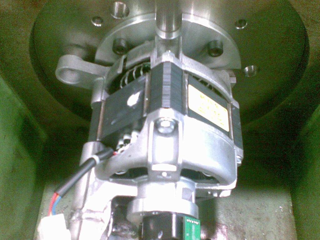
9 Figure 13. Picture of the IM under test. Figure 11. oad step response of the IM drive at 0 rpm. oad torque step is.0 Nm. Figure 14. Picture of the IPM motor under test. Figure 15. Picture of the SPM motor under test. Figure 1. oad step response of the IPM motor drive at 0 rpm. oad torque step is Nm. Figure 16. Picture of the SyR motor under test.
10 [6] R. Bojoi, P. Guglielmi and G. Pellegrino, Sensorless Stator Field Oriented Control for ow Cost Induction Motor Drives with Wide Field Weakening Range Conf. Rec. IEEE IAS 008, pp [7] P.. Jensen and R.D. orenz, A Physically Insightful Approach to the Design and Accuracy Assessment of Flux Observers for Field Oriented Induction Machine Drives, IEEE Trans. on Ind. Applicat., Vol. 30, Issue 1, 1994, pp [8] Holtz, J.;, Sensorless control of induction motor drives, Proceedings of the IEEE, vol.90, no.8, pp , Aug 00 [9] N. Bianchi and S. Bolognani, Magnetic Models of Saturated Interior Permanent Magnet Motors Based on Finite Element Analysis, Conf. Rec. IEEE IAS 1998, Vol.1, pp [10] A. Vagati, M. Pastorelli, F. Scapino and G. Franceschini, Impact of Cross Saturation in Synchronous Reluctance Motors of the Transverse- aminated Type, IEEE Trans. Ind. Appl., Vol.36, No.4, July/August 000, pp [11] Xu, X.; de Doncker, R.; Novotny, D.W.;, Stator flux orientation control of induction machines in the field weakening region, Industry Applications Society Annual Meeting, 1988., Conference Record of the 1988 IEEE, vol., no., pp vol.1, -7 Oct 1988 [1] Xu, X.; Novotny, D.W.;, "Implementation of direct stator flux orientation control on a versatile DSP based system," Industry Applications, IEEE Transactions on, vol.7, no.4, pp , Jul/Aug 1991 [13] W.. Soong, T.J.E. Miller, Field-weakening performance of brushless synchronous AC motor drives, Electric Power Appl., IEE Proceedings, Vol. 141, Issue 6, Nov. 1994, pp [14] A.Vagati, M.Pastorelli, G.Franceschini, and V.Drogoreanu, Digital Observer-Based Control of Synchronous Reluctance Motors, in Conf. Rec of IEEE IAS 1997, Vol.1, pp [15] K. Hurst, T. Habetler, G. Griva and F. Profumo, Zero-Speed Tacholess IM Torque Control: Simply of Matter of Stator Voltage Integration, IEEE Trans. on Ind. Appl., Vol. 34, Issue 4, July/August 1998, pp APPENDIX The motors under test are one commercial motor (IM) and two prototypes (IPM, SyR) for home appliances, while the last machine (SPM) is a prototype for industrial fans. The rating values of all motors are reported in Table I. TABE I - RATING VAUES OF THE FOUR MOTORS UNDER TEST Motor type IM SPM IPM SyR Rated torque (Nm) Rated phase current (A pk) Rated inverter current (A pk) Rated line to line voltage (V pk) Base speed (rpm) Maximum speed (rpm) Back emf at base speed (line to line V pk) / / Characteristic current (A pk) / 50.0 / Pole pairs 1 Stator slots Stator diameter (mm) Stack length (mm)


 received the M.Sc. degree in Electrical Engineering from the Technical University Gh. Asachi Iasi, Romania, in 1993, and the Ph.D.")
11 Gianmario Pellegrino (M 06) received the M.Sc. and Ph.D. degrees in electrical engineering from Politecnico di Torino, Turin, Italy, in 1998 and 00, respectively. He has been a Guest Researcher at Aalborg University, Denmark, in 00. Since 00 he has been with Politecnico di Torino, first as a Research Associate and then as an Assistant Professor, since 007. He has been a visiting fellow at Nottingham University, UK, in 010/011. He is involved in research projects within the industry. He has more than 50 technical papers and one patent. His research areas are the electrical machines and drives, namely, the motor design and the digital control. Dr. Pellegrino is an Associate Editor for the IEEE Transactions on Industry Applications. He is the corecipient of the IEEE-IAS EMC 3 rd Paper Paper Award for ECCE 009, the IEEE-IAS IDC 3 rd Paper Paper Award for ECCE 010 and the ICEM 010 Best Paper Award. Radu Iustin Bojoi (M 06, SM 10) received the M.Sc. degree in Electrical Engineering from the Technical University Gh. Asachi Iasi, Romania, in 1993, and the Ph.D. degree from Politecnico di Torino, Italy, in 003. Since he was an Assistant Professor in the Department of Electrical Drives and Industrial Automation from Technical University of Iasi. In 004 he joined the Department of Electrical Engineering of the Politecnico di Torino, where he is currently an Associate. Professor. His scientific interests regard the design and development of digital control systems in the fields of power electronics, high-performance electrical drives and powerconditioning systems. He has published more than 70 papers in international conferences and technical journals. Paolo Guglielmi (M 07) received the M.Sc. degree in electronic engineering and the Ph.D. degree in electrical engineering from the Politecnico di Torino, Turin, Italy, in 1996 and 001, respectively. In 1997, he joined the Department of Electrical Engineering, Politecnico di Torino, where he became a Researcher in 00. He has authored several papers published in technical journals and conference proceedings. His fields of interest include power electronics, high performance drives, and computer-aided design of electrical machines.
Impact of the Motor Magnetic Model on Direct Flux Vector Control of Interior PM Motors
 Impact of the Motor Magnetic Model on Direct Flux Vector Control of Interior PM Motors Gianmario Pellegrino, Radu Bojoi, Paolo Guglielmi Politecnico di Torino, Italy (gianmario.pellegrino,radu.bojoi,paolo.guglielmi)@polito.it
Design tradeoffs between constant power speed range, uncontrolled generator operation and rated current of IPM motor drives
 Design tradeoffs between constant power speed range, uncontrolled generator operation and rated current of IPM motor drives G. Pellegrino Member, IEEE gianmario.pellegrino@polito.it A. Vagati Fellow, IEEE
POLITECNICO DI TORINO Repository ISTITUZIONALE
 POLITECNICO DI TORINO Repository ISTITUZIONALE Position-sensorless control of permanent-magnet-assisted synchronous reluctance motor Original Position-sensorless control of permanent-magnet-assisted synchronous
Lecture 7: Synchronous Motor Drives
 1 / 46 Lecture 7: Synchronous Motor Drives ELEC-E8402 Control of Electric Drives and Power Converters (5 ECTS) Marko Hinkkanen Spring 2017 2 / 46 Learning Outcomes After this lecture and exercises you
970 IEEE TRANSACTIONS ON INDUSTRY APPLICATIONS, VOL. 48, NO. 3, MAY/JUNE 2012
 970 IEEE TRANSACTIONS ON INDUSTRY APPLICATIONS, VOL. 48, NO. 3, MAY/JUNE 2012 Control Method Suitable for Direct-Torque-Control-Based Motor Drive System Satisfying Voltage and Current Limitations Yukinori
INTERIOR Permanent Magnet (IPM) machines have been
 machines have been") 1 Permanent Magnet minimization in PM-Assisted Synchronous Reluctance motors for wide speed range P. Guglielmi, B. Boazzo, E. Armando, G. Pellegrino and A. Vagati Department of Electrical Engineering -
1 Permanent Magnet minimization in PM-Assisted Synchronous Reluctance motors for wide speed range P. Guglielmi, B. Boazzo, E. Armando, G. Pellegrino and A. Vagati Department of Electrical Engineering -
POLITECNICO DI TORINO Repository ISTITUZIONALE
 POLITECNICO DI TORINO Repository ISTITUZIONALE Ferrite Assisted Synchronous Reluctance Machines: a General Approach Original Ferrite Assisted Synchronous Reluctance Machines: a General Approach / A. Vagati;
A Direct Torque Controlled Induction Motor with Variable Hysteresis Band
 UKSim 2009: th International Conference on Computer Modelling and Simulation A Direct Torque Controlled Induction Motor with Variable Hysteresis Band Kanungo Barada Mohanty Electrical Engineering Department,
Zero speed sensorless drive capability of fractional slot inset PM machine
 Zero speed sensorless drive capability of fractional slot inset PM Adriano Faggion Nicola Bianchi Silverio Bolognani Emanuele Fornasiero Electric Drives Laboratory Department of Industrial Engineering
Direct Flux Vector Control Of Induction Motor Drives With Maximum Efficiency Per Torque
 Direct Flux Vector Control Of Induction Motor Drives With Maximum Efficiency Per Torque S. Rajesh Babu 1, S. Sridhar 2 1 PG Scholar, Dept. Of Electrical & Electronics Engineering, JNTUACEA, Anantapuramu,
DTC Based Induction Motor Speed Control Using 10-Sector Methodology For Torque Ripple Reduction
 DTC Based Induction Motor Speed Control Using 10-Sector Methodology For Torque Ripple Reduction S. Pavithra, Dinesh Krishna. A. S & Shridharan. S Netaji Subhas Institute of Technology, Delhi University
2016 Kappa Electronics Motor Control Training Series Kappa Electronics LLC. -V th. Dave Wilson Co-Owner Kappa Electronics.
 2016 Kappa Electronics Motor Control Training Series 2016 Kappa Electronics C V th CoOwner Kappa Electronics www.kappaiq.com Benefits of Field Oriented Control NewtonMeters Maximum Torque Per Amp (MTPA)
THE approach of sensorless speed control of induction motors
 IEEE TRANSACTIONS ON INDUSTRY APPLICATIONS, VOL. 41, NO. 4, JULY/AUGUST 2005 1039 An Adaptive Sliding-Mode Observer for Induction Motor Sensorless Speed Control Jingchuan Li, Longya Xu, Fellow, IEEE, and
Three phase induction motor using direct torque control by Matlab Simulink
 Three phase induction motor using direct torque control by Matlab Simulink Arun Kumar Yadav 1, Dr. Vinod Kumar Singh 2 1 Reaserch Scholor SVU Gajraula Amroha, U.P. 2 Assistant professor ABSTRACT Induction
Evaluation Method to Estimate Position Control Error in Position Sensorless Control Based on Pattern Matching Method
 IEEJ Journal of Industry Applications Vol.7 No.1 pp.73 79 DOI: 10.1541/ieejjia.7.73 Paper Evaluation Method to Estimate Position Control Error in Position Sensorless Control Based on Pattern Matching Method
International Journal of Advance Engineering and Research Development SIMULATION OF FIELD ORIENTED CONTROL OF PERMANENT MAGNET SYNCHRONOUS MOTOR
 Scientific Journal of Impact Factor(SJIF): 3.134 e-issn(o): 2348-4470 p-issn(p): 2348-6406 International Journal of Advance Engineering and Research Development Volume 2,Issue 4, April -2015 SIMULATION
Lecture 8: Sensorless Synchronous Motor Drives
 1 / 22 Lecture 8: Sensorless Synchronous Motor Drives ELEC-E8402 Control of Electric Drives and Power Converters (5 ECTS) Marko Hinkkanen Spring 2017 2 / 22 Learning Outcomes After this lecture and exercises
POLITECNICO DI TORINO Repository ISTITUZIONALE
 POLITECNICO DI TORINO Repository ISTITUZIONALE Optimal design of IPM-PMASR motors for wide constant power speed range applications Original Optimal design of IPM-PMASR motors for wide constant power speed
Independent Control of Speed and Torque in a Vector Controlled Induction Motor Drive using Predictive Current Controller and SVPWM
 Independent Control of Speed and Torque in a Vector Controlled Induction Motor Drive using Predictive Current Controller and SVPWM Vandana Peethambaran 1, Dr.R.Sankaran 2 Assistant Professor, Dept. of
Simplified EKF Based Sensorless Direct Torque Control of Permanent Magnet Brushless AC Drives
 International Journal of Automation and Computing (24) 35-4 Simplified EKF Based Sensorless Direct Torque Control of Permanent Magnet Brushless AC Drives Yong Liu, Ziqiang Zhu, David Howe Department of
Mathematical Modeling and Dynamic Simulation of a Class of Drive Systems with Permanent Magnet Synchronous Motors
 Applied and Computational Mechanics 3 (2009) 331 338 Mathematical Modeling and Dynamic Simulation of a Class of Drive Systems with Permanent Magnet Synchronous Motors M. Mikhov a, a Faculty of Automatics,
A new FOC technique based on predictive current control for PMSM drive
 ISSN 1 746-7, England, UK World Journal of Modelling and Simulation Vol. 5 (009) No. 4, pp. 87-94 A new FOC technique based on predictive current control for PMSM drive F. Heydari, A. Sheikholeslami, K.
Modelling of Closed Loop Speed Control for Pmsm Drive
 Modelling of Closed Loop Speed Control for Pmsm Drive Vikram S. Sathe, Shankar S. Vanamane M. Tech Student, Department of Electrical Engg, Walchand College of Engineering, Sangli. Associate Prof, Department
Novel DTC-SVM for an Adjustable Speed Sensorless Induction Motor Drive
 Novel DTC-SVM for an Adjustable Speed Sensorless Induction Motor Drive Nazeer Ahammad S1, Sadik Ahamad Khan2, Ravi Kumar Reddy P3, Prasanthi M4 1*Pursuing M.Tech in the field of Power Electronics 2*Working
Control of Wind Turbine Generators. James Cale Guest Lecturer EE 566, Fall Semester 2014 Colorado State University
 Control of Wind Turbine Generators James Cale Guest Lecturer EE 566, Fall Semester 2014 Colorado State University Review from Day 1 Review Last time, we started with basic concepts from physics such as
ISSN: (Online) Volume 2, Issue 2, February 2014 International Journal of Advance Research in Computer Science and Management Studies
 Volume 2, Issue 2, February 2014 International Journal of Advance Research in Computer Science and Management Studies") ISSN: 2321-7782 (Online) Volume 2, Issue 2, February 2014 International Journal of Advance Research in Computer Science and Management Studies Research Article / Paper / Case Study Available online at:
ISSN: 2321-7782 (Online) Volume 2, Issue 2, February 2014 International Journal of Advance Research in Computer Science and Management Studies Research Article / Paper / Case Study Available online at:
Accurate Joule Loss Estimation for Rotating Machines: An Engineering Approach
 Accurate Joule Loss Estimation for Rotating Machines: An Engineering Approach Adeeb Ahmed Department of Electrical and Computer Engineering North Carolina State University Raleigh, NC, USA aahmed4@ncsu.edu
2014 Texas Instruments Motor Control Training Series. -V th. Dave Wilson
 204 Texas Instruments Motor Control Training Series V th Speed Sensorless FOC P Commanded Rotor Speed Commanded i d = 0 Commanded i q (torque) P I P V d V q Reverse ClarkePark Transform θ d V a V b V c
EXPERIMENTAL COMPARISON OF LAMINATION MATERIAL CASE OF SWITCHING FLUX SYNCHRONOUS MACHINE WITH HYBRID EXCITATION
 EXPERIMENTAL COMPARISON OF LAMINATION MATERIAL CASE OF SWITCHING FLUX SYNCHRONOUS MACHINE WITH HYBRID EXCITATION Emmanuel Hoang, Sami Hlioui, Michel Lécrivain, Mohamed Gabsi To cite this version: Emmanuel
Sensorless Control for High-Speed BLDC Motors With Low Inductance and Nonideal Back EMF
 Sensorless Control for High-Speed BLDC Motors With Low Inductance and Nonideal Back EMF P.Suganya Assistant Professor, Department of EEE, Bharathiyar Institute of Engineering for Women Salem (DT). Abstract
On-line Parameter Estimation Method for IPMSM Based on Decoupling Control
 World Electric Vehicle Journal Vol. 4 - ISSN 232-6653 - 21 WEVA Page61 EVS25 Shenzhen, China, Nov 5-9, 21 On-line Parameter Estimation Method for IPMSM Based on Decoupling Control Aimeng Wang,Xingwang
A Novel Three-phase Matrix Converter Based Induction Motor Drive Using Power Factor Control
 Australian Journal of Basic and Applied Sciences, 8(4) Special 214, Pages: 49-417 AENSI Journals Australian Journal of Basic and Applied Sciences ISSN:1991-8178 Journal home page: www.ajbasweb.com A Novel
PERFORMANCE ANALYSIS OF DIRECT TORQUE CONTROL OF 3-PHASE INDUCTION MOTOR
 PERFORMANCE ANALYSIS OF DIRECT TORQUE CONTROL OF 3-PHASE INDUCTION MOTOR 1 A.PANDIAN, 2 Dr.R.DHANASEKARAN 1 Associate Professor., Department of Electrical and Electronics Engineering, Angel College of
the machine makes analytic calculation of rotor position impossible for a given flux linkage and current value.
 COMPARISON OF FLUX LINKAGE ESTIMATORS IN POSITION SENSORLESS SWITCHED RELUCTANCE MOTOR DRIVES Erkan Mese Kocaeli University / Technical Education Faculty zmit/kocaeli-turkey email: emese@kou.edu.tr ABSTRACT
Speed Control of Induction Motor Drives using Nonlinear Adaptive Controller
 Speed Control of Induction Motor Drives using Nonlinear Adaptive Controller 1 Sarojini.P, 2 Mr. R Issan Raj M.E Control and Instrumentation Engineering Valliammai Engineering College Kancheepuram District
A New Current Model Flux Observer for Wide Speed Range Sensorless Control of an Induction Machine
 IEEE TRANSACTIONS ON POWER ELECTRONICS, VOL. 17, NO. 6, NOVEMBER 2002 1041 A New Current Model Flux Observer for Wide Speed Range Sensorless Control of an Induction Machine Habib-ur Rehman, Member, IEEE,
TODAY, a particular emphasis is given to the environmental
 IEEE TRANSACTIONS ON INDUSTRIAL ELECTRONICS, VOL. 52, NO. 4, AUGUST 2005 1153 Efficiency Enhancement of Permanent-Magnet Synchronous Motor Drives by Online Loss Minimization Approaches Calogero Cavallaro,
Robust Controller Design for Speed Control of an Indirect Field Oriented Induction Machine Drive
 Leonardo Electronic Journal of Practices and Technologies ISSN 1583-1078 Issue 6, January-June 2005 p. 1-16 Robust Controller Design for Speed Control of an Indirect Field Oriented Induction Machine Drive
An improved deadbeat predictive current control for permanent magnet linear synchronous motor
 Indian Journal of Engineering & Materials Sciences Vol. 22, June 2015, pp. 273-282 An improved deadbeat predictive current control for permanent magnet linear synchronous motor Mingyi Wang, iyi i, Donghua
Implementation of Twelve-Sector based Direct Torque Control for Induction motor
 International Journal of Engineering Science Invention ISSN (Online): 2319 6734, ISSN (Print): 2319 6726 Volume 2 Issue 4 ǁ April. 2013 ǁ PP.32-37 Implementation of Twelve-Sector based Direct Torque Control
Comparisons of direct and adaptative optimal controls for interior permanent magnet synchronous integrated starter generator
 Comparisons of direct and adaptative optimal controls for interior permanent magnet synchronous integrated starter generator L. Chédot Valeo Electrical System 2, rue A. Boulle / BP15 9417 Créteil Cedex
PRINCIPLE OF DESIGN OF FOUR PHASE LOW POWER SWITCHED RELUCTANCE MACHINE AIMED TO THE MAXIMUM TORQUE PRODUCTION
 Journal of ELECTRICAL ENGINEERING, VOL. 55, NO. 5-6, 24, 138 143 PRINCIPLE OF DESIGN OF FOUR PHASE LOW POWER SWITCHED RELUCTANCE MACHINE AIMED TO THE MAXIMUM TORQUE PRODUCTION Martin Lipták This paper
Control Methods for Doubly-Fed Reluctance Machines
 Control Methods for Doubly-Fed Reluctance Machines MILUTIN JOVANOVIĆ and KRISHNA BUSAWON School of Computing, Engineering and Information Sciences University of Northumbria at Newcastle Newcastle upon
IN the above paper [1] the local observability of the induction machine (IM) and the permanent
![IN the above paper [1] the local observability of the induction machine (IM) and the permanent](/thumbs/93/112641715.jpg "IN the above paper [1] the local observability of the induction machine (IM) and the permanent") IEEE TRANSACTIONS ON INDUSTRIAL ELECTRONICS 1 Discussion on AC Drive Observability Analysis Mohamad Koteich, Student Member, IEEE, Abdelmalek Maloum, Gilles Duc and Guillaume Sandou arxiv:1512.01462v1
IEEE TRANSACTIONS ON INDUSTRIAL ELECTRONICS 1 Discussion on AC Drive Observability Analysis Mohamad Koteich, Student Member, IEEE, Abdelmalek Maloum, Gilles Duc and Guillaume Sandou arxiv:1512.01462v1
A New Predictive Control Strategy Dedicated to Salient Pole Synchronous Machines
 A New Predictive Control Strategy Dedicated to Salient Pole Synchronous Machines Nicolas Patin Member IEEE University of Technology of Compiègne Laboratoire d Electromécanique de Compiègne Rue Personne
Parameter Prediction and Modelling Methods for Traction Motor of Hybrid Electric Vehicle
 Page 359 World Electric Vehicle Journal Vol. 3 - ISSN 232-6653 - 29 AVERE Parameter Prediction and Modelling Methods for Traction Motor of Hybrid Electric Vehicle Tao Sun, Soon-O Kwon, Geun-Ho Lee, Jung-Pyo
DESIGN AND IMPLEMENTATION OF SENSORLESS SPEED CONTROL FOR INDUCTION MOTOR DRIVE USING AN OPTIMIZED EXTENDED KALMAN FILTER
 INTERNATIONAL JOURNAL OF ELECTRONICS AND COMMUNICATION ENGINEERING & TECHNOLOGY (IJECET) International Journal of Electronics and Communication Engineering & Technology (IJECET), ISSN 0976 ISSN 0976 6464(Print)
Sensorless DTC-SVM of Induction Motor by Applying Two Neural Controllers
 Sensorless DTC-SVM of Induction Motor by Applying Two Neural Controllers Abdallah Farahat Mahmoud Dept. of Electrical Engineering, Al-Azhar University, Qena, Egypt engabdallah2012@azhar.edu.eg Adel S.
Magnetic Saturation and Iron Loss Influence on Max Torque per Ampere Current Vector Variation of Synchronous Reluctance Machine
 EVS28 KINTEX, Korea, May 3-6, 215 Magnetic Saturation and Iron Loss Influence on Max Torque per Ampere Current Vector Variation of Synchronous Reluctance Machine Huai-Cong Liu 1, In-Gun Kim 1, Ju lee 1
Dynamic Modeling of Surface Mounted Permanent Synchronous Motor for Servo motor application
 797 Dynamic Modeling of Surface Mounted Permanent Synchronous Motor for Servo motor application Ritu Tak 1, Sudhir Y Kumar 2, B.S.Rajpurohit 3 1,2 Electrical Engineering, Mody University of Science & Technology,
Chapter 2 Synchronous Reluctance and PM Assisted Reluctance Motors
 Chapter 2 Synchronous Reluctance and PM Assisted Reluctance Motors Nicola Bianchi Abstract This chapter focuses on the key notions about analysis and design of synchronous reluctance and permanent magnet
Robust Speed Controller Design for Permanent Magnet Synchronous Motor Drives Based on Sliding Mode Control
 Available online at www.sciencedirect.com ScienceDirect Energy Procedia 88 (2016 ) 867 873 CUE2015-Applied Energy Symposium and Summit 2015: ow carbon cities and urban energy systems Robust Speed Controller
Small-Signal Analysis of a Saturated Induction Motor
 1 Small-Signal Analysis of a Saturated Induction Motor Mikaela Ranta, Marko Hinkkanen, Anna-Kaisa Repo, and Jorma Luomi Helsinki University of Technology Department of Electrical Engineering P.O. Box 3,
Inductance Testing According to the New IEEE Std 1812 Application and Possible Extensions for IPM Machines
 Inductance Testing According to the New IEEE Std 1812 Application and Possible Extensions for IPM Machines Vandana Rallabandi Narges Taran Dan M. Ionel Department of Electrical and Computer Engineering
Wide-Speed Operation of Direct Torque-Controlled Interior Permanent-Magnet Synchronous Motors
 Wide-Speed Operation of Direct Torque-Controlled Interior Permanent-Magnet Synchronous Motors Adina Muntean, M.M. Radulescu Small Electric Motors and Electric Traction (SEMET) Group, Technical University
Analytical Model for Sizing the Magnets of Permanent Magnet Synchronous Machines
 Journal of Electrical Engineering 3 (2015) 134-141 doi: 10.17265/2328-2223/2015.03.004 D DAVID PUBLISHING Analytical Model for Sizing Magnets of Permanent Magnet Synchronous Machines George Todorov and
An adaptive sliding mode control scheme for induction motor drives
 An adaptive sliding mode control scheme for induction motor drives Oscar Barambones, Patxi Alkorta, Aitor J. Garrido, I. Garrido and F.J. Maseda ABSTRACT An adaptive sliding-mode control system, which
Sensorless Field Oriented Control of Permanent Magnet Synchronous Motor
 International Journal of Current Engineering and Technology E-ISSN 2277 4106, P-ISSN 2347 5161 2015 INPRESSCO, All Rights Reserved Available at http://inpressco.com/category/ijcet Research Article Sensorless
Improved efficiency of a fan drive system without using an encoder or current sensors
 Improved efficiency of a fan drive system without using an encoder or current sensors Tian-Hua Liu, Jyun-Jie Huang Department of Electrical Engineering, National Taiwan University of Science Technology,
Comparative Analysis of Speed Control of Induction Motor by DTC over Scalar Control Technique
 Comparative Analysis of Speed Control of Induction Motor by DTC over Scalar Control Technique S.Anuradha 1, N.Amarnadh Reddy 2 M.Tech (PE), Dept. of EEE, VNRVJIET, T.S, India 1 Assistant Professor, Dept.
MATLAB SIMULINK Based DQ Modeling and Dynamic Characteristics of Three Phase Self Excited Induction Generator
 628 Progress In Electromagnetics Research Symposium 2006, Cambridge, USA, March 26-29 MATLAB SIMULINK Based DQ Modeling and Dynamic Characteristics of Three Phase Self Excited Induction Generator A. Kishore,
Proceedings of the 6th WSEAS/IASME Int. Conf. on Electric Power Systems, High Voltages, Electric Machines, Tenerife, Spain, December 16-18,
 Proceedings of the 6th WSEAS/IASME Int. Conf. on Electric Power Systems, High Voltages, Electric Machines, Tenerife, Spain, December 16-18, 2006 196 A Method for the Modeling and Analysis of Permanent
AC Induction Motor Stator Resistance Estimation Algorithm
 7th WSEAS International Conference on Electric Power Systems, High Voltages, Electric Machines, Venice, Italy, November 21-23, 27 86 AC Induction Motor Stator Resistance Estimation Algorithm PETR BLAHA
CHAPTER 2 MODELLING OF INTERIOR PERMANENT MAGNET SYNCHRONOUS MOTOR
 21 CHAPTER 2 MODELLING OF INTERIOR PERMANENT MAGNET SYNCHRONOUS MOTOR 2.1 INTRODUCTION The need for adjustable speed drives in industrial applications has been increasing progressively. The variable speed
This is a repository copy of Influence of skew and cross-coupling on flux-weakening performance of permanent-magnet brushless AC machines.
 This is a repository copy of Influence of skew and cross-coupling on flux-weakening performance of permanent-magnet brushless AC machines. White Rose Research Online URL for this paper: http://eprints.whiterose.ac.uk/8610/
Static Characteristics of Switched Reluctance Motor 6/4 By Finite Element Analysis
 Australian Journal of Basic and Applied Sciences, 5(9): 1403-1411, 2011 ISSN 1991-8178 Static Characteristics of Switched Reluctance Motor 6/4 By Finite Element Analysis 1 T. Jahan. 2 M.B.B. Sharifian
1234. Sensorless speed control of a vector controlled three-phase induction motor drive by using MRAS
 1234. Sensorless speed control of a vector controlled three-phase induction motor drive by using MRAS Ali Saffet Altay 1, Mehmet Emin Tacer 2, Ahmet Faik Mergen 3 1, 3 Istanbul Technical University, Department
DEVELOPMENT OF DIRECT TORQUE CONTROL MODELWITH USING SVI FOR THREE PHASE INDUCTION MOTOR
 DEVELOPMENT OF DIRECT TORQUE CONTROL MODELWITH USING SVI FOR THREE PHASE INDUCTION MOTOR MUKESH KUMAR ARYA * Electrical Engg. Department, Madhav Institute of Technology & Science, Gwalior, Gwalior, 474005,
Torque Ripple Reduction Using Torque Compensation Effect of an Asymmetric Rotor Design in IPM Motor
 Journal of Magnetics 22(2), 266-274 (2017) ISSN (Print) 1226-1750 ISSN (Online) 2233-6656 https://doi.org/10.4283/jmag.2017.22.2.266 Torque Ripple Reduction Using Torque Compensation Effect of an Asymmetric
3 d Calculate the product of the motor constant and the pole flux KΦ in this operating point. 2 e Calculate the torque.
 Exam Electrical Machines and Drives (ET4117) 11 November 011 from 14.00 to 17.00. This exam consists of 5 problems on 4 pages. Page 5 can be used to answer problem 4 question b. The number before a question
DIRECT TORQUE CONTROL OF PERMANENT MAGNET SYNCHRONOUS MOTOR USING TWO LEVEL INVERTER- SURVEY PAPER
 DIRECT TORQUE CONTROL OF PERMANENT MAGNET SYNCHRONOUS MOTOR USING TWO LEVEL INVERTER- SURVEY PAPER 1 PREETI SINGH, BHUPAL SINGH 1 M.Tech (scholar) Electrical Power & Energy System, lecturer Ajay Kumar
Sensorless Sliding Mode Control of Induction Motor Drives
 Sensorless Sliding Mode Control of Induction Motor Drives Kanungo Barada Mohanty Electrical Engineering Department, National Institute of Technology, Rourkela-7698, India E-mail: kbmohanty@nitrkl.ac.in
Design and implementation of a sliding-mode observer of the rotor flux and rotor speed in induction machines
 1 Design and implementation of a sliding-mode observer of the rotor flux and rotor speed in induction machines João Ferraz, Paulo Branco Phd. Abstract A sliding-mode observer for the rotor flux and speed
Indirect Field Orientation for Induction Motors without Speed Sensor
 Indirect Field Orientation for Induction Motors without Speed Sensor C. C. de Azevedol, C.B. Jacobinal, L.A.S. Ribeiro2, A.M.N. Lima1 and A.C. Oliveira1j2 UFPB/CCT/DEE/LEIAM - Campus II - Caixa Postal
Simulation of Direct Torque Control of Induction motor using Space Vector Modulation Methodology
 International OPEN ACCESS Journal Of Modern Engineering Research (IJMER) Simulation of Direct Torque Control of Induction motor using Space Vector Modulation Methodology Arpit S. Bhugul 1, Dr. Archana
Internal Model Control Approach to PI Tunning in Vector Control of Induction Motor
 Internal Model Control Approach to PI Tunning in Vector Control of Induction Motor Vipul G. Pagrut, Ragini V. Meshram, Bharat N. Gupta, Pranao Walekar Department of Electrical Engineering Veermata Jijabai
Comparison Between Direct and Indirect Field Oriented Control of Induction Motor
 Comparison Between Direct and Indirect Field Oriented Control of Induction Motor Venu Gopal B T Research Scholar, Department of Electrical Engineering UVCE, Bangalore University, Bengaluru ABSTRACT - Vector
Anakapalli Andhra Pradesh, India I. INTRODUCTION
 Robust MRAS Based Sensorless Rotor Speed Measurement of Induction Motor against Variations in Stator Resistance Using Combination of Back Emf and Reactive Power Methods Srikanth Mandarapu Pydah College
Stepping Motors. Chapter 11 L E L F L D
 Chapter 11 Stepping Motors In the synchronous motor, the combination of sinusoidally distributed windings and sinusoidally time varying current produces a smoothly rotating magnetic field. We can eliminate
Robust sliding mode speed controller for hybrid SVPWM based direct torque control of induction motor
 ISSN 1 746-7233, England, UK World Journal of Modelling and Simulation Vol. 3 (2007) No. 3, pp. 180-188 Robust sliding mode speed controller for hybrid SVPWM based direct torque control of induction motor
Sensorless Speed Control for PMSM Based On the DTC Method with Adaptive System R. Balachandar 1, S. Vinoth kumar 2, C. Vignesh 3
 Sensorless Speed Control for PMSM Based On the DTC Method with Adaptive System R. Balachandar 1, S. Vinoth kumar 2, C. Vignesh 3 P.G Scholar, Sri Subramanya College of Engg & Tech, Palani, Tamilnadu, India
SPEED CONTROL OF PMSM BY USING DSVM -DTC TECHNIQUE
 SPEED CONTROL OF PMSM BY USING DSVM -DTC TECHNIQUE J Sinivas Rao #1, S Chandra Sekhar *2, T Raghu #3 1 Asst Prof, Dept Of EEE, Anurag Engineering College, AP, INDIA 3 Asst Prof, Dept Of EEE, Anurag Engineering
Sliding-Mode Observer based Direct Torque Control of an IPM- Synchronous Motor Drive at Very Low Speed
 IOSR Journal of Electrical and Electronics Engineering (IOSR-JEEE) e-issn: 2278-1676,p-ISSN: 2320-3331, Volume 9, Issue 6 Ver. IV (Nov Dec. 2014), PP 08-17 www.iosrjournals.org Sliding-Mode Observer based
MODELING AND HIGH-PERFORMANCE CONTROL OF ELECTRIC MACHINES
 MODELING AND HIGH-PERFORMANCE CONTROL OF ELECTRIC MACHINES JOHN CHIASSON IEEE PRESS ü t SERIES ON POWER ENGINEERING IEEE Press Series on Power Engineering Mohamed E. El-Hawary, Series Editor The Institute
A Saturating Lumped-Parameter Model for an Interior PM Synchronous Machine
 IEEE TRANSACTIONS ON INDUSTRY APPLICATIONS, VOL. 38, NO. 3, MAY/JUNE 2002 645 A Saturating Lumped-Parameter Model for an Interior PM Synchronous Machine Edward C. Lovelace, Member, IEEE, Thomas M. Jahns,
Torque Maximizing and Flux Weakening Control of Synchronous Machines
 Waqar Ahmed Khan Torque Maximizing and Flux Weakening Control of Synchronous Machines School of Electrical Engineering Thesis submitted for examination for the degree of Master of Science in Technology.
Inertia Identification and Auto-Tuning. of Induction Motor Using MRAS
 Inertia Identification and Auto-Tuning of Induction Motor Using MRAS Yujie GUO *, Lipei HUANG *, Yang QIU *, Masaharu MURAMATSU ** * Department of Electrical Engineering, Tsinghua University, Beijing,
EFFICIENCY OPTIMIZATION OF VECTOR-CONTROLLED INDUCTION MOTOR DRIVE
 EFFICIENCY OPTIMIZATION OF VECTOR-CONTROLLED INDUCTION MOTOR DRIVE Hussein Sarhan Department of Mechatronics Engineering, Faculty of Engineering Technology, Amman, Jordan ABSTRACT This paper presents a
Sensorless Control of Two-phase Switched Reluctance Drive in the Whole Speed Range
 Sensorless Control of Two-phase Switched Reluctance Drive in the Whole Speed Range Dmitry Aliamkin, Alecksey Anuchin, Maxim Lashkevich Electric Drives Department of Moscow Power Engineering Institute,
A Method for Magnetizing Curve Identification in Rotor Flux Oriented Induction Machines
 IEEE TRANSACTIONS ON ENERGY CONVERSION, VOL. 15, NO. 2, JUNE 2000 157 A Method for Magnetizing Curve Identification in Rotor Flux Oriented Induction Machines Emil Levi, Member, IEEE, Matija Sokola, and
Modeling and Simulation of Flux-Optimized Induction Motor Drive
 Research Journal of Applied Sciences, Engineering and Technology 2(6): 603-613, 2010 ISSN: 2040-7467 Maxwell Scientific Organization, 2010 Submitted Date: July 21, 2010 Accepted Date: August 20, 2010 Published
SWITCHED reluctance motor (SRM) drives have been
 drives have been") IEEE TRANSACTIONS ON INDUSTRIAL ELECTRONICS, VOL. 45, NO. 5, OCTOBER 1998 815 A Novel Power Converter with Voltage-Boosting Capacitors for a Four-Phase SRM Drive Yasser G. Dessouky, Barry W. Williams,
IEEE TRANSACTIONS ON INDUSTRIAL ELECTRONICS, VOL. 45, NO. 5, OCTOBER 1998 815 A Novel Power Converter with Voltage-Boosting Capacitors for a Four-Phase SRM Drive Yasser G. Dessouky, Barry W. Williams,
Speed Sensor less Control and Estimation Based on Mars for Pmsm under Sudden Load Change
 International Journal of Engineering Inventions e-issn: 2278-7461, p-isbn: 2319-6491 Volume 2, Issue 3 (February 2013) PP: 77-86 Speed Sensor less Control and Estimation Based on Mars for Pmsm under Sudden
Sensorless Torque and Speed Control of Traction Permanent Magnet Synchronous Motor for Railway Applications based on Model Reference Adaptive System
 5 th SASTech 211, Khavaran Higher-education Institute, Mashhad, Iran. May 12-14. 1 Sensorless Torue and Speed Control of Traction Permanent Magnet Synchronous Motor for Railway Applications based on Model
CPPM Mahine: A Synchronous Permanent Magnet Machine with Field Weakening
 CPPM Mahine: A Synchronous Permanent Magnet Machine with Field Weakening Juan A. Tapia, Thomas A. Lipo, Fellow, IEEE Dept. of Electrical and Computer Engineering University of Wisconsin-Madison 45 Engineering
HIGH PERFORMANCE ADAPTIVE INTELLIGENT DIRECT TORQUE CONTROL SCHEMES FOR INDUCTION MOTOR DRIVES
 HIGH PERFORMANCE ADAPTIVE INTELLIGENT DIRECT TORQUE CONTROL SCHEMES FOR INDUCTION MOTOR DRIVES M. Vasudevan and R. Arumugam Department of Electrical and Electronics Engineering, Anna University, Chennai,
Mathematical Modelling of Permanent Magnet Synchronous Motor with Rotor Frame of Reference
 Mathematical Modelling of Permanent Magnet Synchronous Motor with Rotor Frame of Reference Mukesh C Chauhan 1, Hitesh R Khunt 2 1 P.G Student (Electrical),2 Electrical Department, AITS, rajkot 1 mcchauhan1@aits.edu.in
INDUCTION MOTOR MODEL AND PARAMETERS
 APPENDIX C INDUCTION MOTOR MODEL AND PARAMETERS C.1 Dynamic Model of the Induction Motor in Stationary Reference Frame A three phase induction machine can be represented by an equivalent two phase machine
Guangjin Li, Javier Ojeda, Emmanuel Hoang, Mohamed Gabsi, Cederic Balpe. To cite this version:
 Design of Double Salient Interior Permanent Magnet Machine Based on Mutually Coupled Reluctance Machine for Increasing the Torque Density and Flux-Weakening Capability Guangjin Li, Javier Ojeda, Emmanuel
A NEW STRUCTURE OF A SWITCHING FLUX SYNCHRONOUS POLYPHASED MACHINE WITH HYBRID EXCITATION
 A NEW STRUCTURE OF A SWITCHING FLUX SYNCHRONOUS POLYPHASED MACHINE WITH HYBRID EXCITATION Emmanuel Hoang, Michel Lécrivain, Mohamed Gabsi To cite this version: Emmanuel Hoang, Michel Lécrivain, Mohamed