Basics of Impedance Spectroscopy
|
|
|
- Cameron Black
- 5 years ago
- Views:
Transcription
1 Basics of Impedance Spectroscopy (<1% of the entire topic!) B. Markovsky, Summer Courses, Bar-Ilan University, September 2014
2 The main goal of this presentation is a brief Introduction to EIS


3 Electrochemical Techniques
4 CVs of LiMO 2 electrode. Dynamic technique. t 50 V/s V 10 V/s 3.69 V 10 T=30 0 C
 Relaxation:")
5 Time domain. Current = f(time) Relaxation: Current decays with time
6 An Electrochemical Impedance Spectrum 1 µhz Frequency domain from high to low frequencies 100 khz
7 The number of papers on EIS has doubled every 4 5 years!
8 AC vs. DC methods Potential Current time time Once we apply DC methods, the cell is totally changed. Surface and volume changes Phase transitions Electrolyte oxidation/reduction Potential time Current time For AC methods, very small perturbation is applied. Nearly non-destructive! Cell is unchanged!

9 Alternating current (ac) methods: the merits To grasp the entire features of the system: Sometimes we need X-ray to see the inside of our body. Sometimes we need ac methods to see the inside of an electrochemical cell.
10 ELECTROCHEMICAL IMPEDANCE SPECTROSCOPY Electrochemical Impedance Spectroscopy (EIS) is actually a special case among electrochemical techniques. It is based on the perturbation of an equilibrium state, while the standard techniques are dynamic (e.g. CV) or are based on the change from an initial equilibrium state to a different, final state (e.g. potential step, chronocoulometry). Hence, EIS is a small-signal technique where, in the analysis of the impedance spectra, a linear current-voltage relation is assumed.
11 ELECTROCHEMICAL IMPEDANCE SPECTROSCOPY Impedance spectroscopy is a non-destructive technique and so can provide time dependent information about the properties of a system but also about ongoing processes such as: - corrosion of metals, - discharge and charge of batteries, - electrochemical reactions in fuel cells, capacitors or any other electrochemical process.
12 Resistance. Ideal Resistor Everyone knows about the concept of electrical resistance. What is resistance? It is the ability of a circuit element to resist the flow of electrical current. Ohm's law defines resistance R in terms of the ratio between voltage, E, and current, I. R Et () It ()
13 Ideal Resistor R This relationship is limited to only one circuit element ---- the ideal resistor! An ideal resistor has several simplifying properties: It follows Ohm's law at all current and voltage levels. It's resistance value is independent on frequency. AC current and voltage signals through a resistor are in phase with each other. Et () It ()
14 In a Real World: Circuit elements exhibit much more complex behavior. In place of resistance, we use impedance, which is a more general circuit parameter. Like resistance, impedance is a measure of the ability of a circuit to resist the flow of electrical current. Electrochemical Impedance is normally measured using a small excitation signal (3 10 mv). This is done so that the cell's response is pseudo-linear. In a pseudo-linear system, the current response to a sinusoidal potential will be a sinusoid at the same frequency but shifted in phase.
15 Sinusoidal Current Response in a Linear System Phasor (Vector) diagram for an ac-voltage E time I time - phase angle Phaseshift Phase-shift A purely sinusoidal voltage: E t =E 0 sin t E is the amplitude of the signal, and is the radial (angular) frequency. (in radians/second) and frequency f (in Hertz (1/sec) are related as: =2 f
16 Phasor (Rotating Vector) diagram
17 Response di of de from the Current / Potential relation: We can disturb an electrical element at a certain potential E with a small perturbation de and we will get at the current I a small response perturbation di. In the first approximation, as the perturbation de is small, the response di will be a linear response as well. An oval is plotted. This oval is known as a "Lissajous figure".
18 Complex Numbers In Electrical Engineering to add together resistances, currents or DC voltages real numbers are used. But real numbers are not the only kind of numbers we need to use especially when dealing with frequency dependent sinusoidal sources and vectors. Complex Numbers were introduced to allow complex equations to be solved with numbers that are the square roots of negative numbers, -1. i= -1
19 Complex Number = Real number + Imaginary number In electrical engineering, -1 is called an imaginary number and to distinguish an imaginary number from a real number the letter j known commonly in electrical engineering as the j-operator, is used. The letter j is placed in front of a real number to signify its imaginary number operation. Examples of imaginary numbers are: j3, j12, j100 etc. A complex number consists of two distinct but very much related parts, a Real Number plus an Imaginary Number.
20 Complex Numbers. Complex Plane Complex Numbers represent points in a two-dimensional complex plane that are referenced to two distinct axes. The horizontal axis is called the Real Axis while the vertical axis is called the Imaginary Axis. The real and imaginary parts of a complex number, Z are abbreviated as Re(z) and Im(z).
21 Two Dimensional Complex Plane (Four Quadrant Argand Diagram) Z= -8 j5 Z = 5 + j0 Z = 0 + j4 Negative Imaginary Axis


22 Complex Numbers. Complex Plane Imaginary axis i= -1 Real axis The plane of complex numbers spanned by the vectors 1 and i, where i is the imaginary number. Every complex number corresponds to a unique point in the complex plane (Argand or Gauss plane).
23 Complex writting Using Euler s relationship exp( i ) cos isin it is possible to express the impedance as a complex function. The potential is described as, Z() t E( t) E0 exp( j t) and the current response as, 0 I( t) I exp( i t i ) The impedance is then represented as a complex number: E Z Z0exp( i ) Z0(cos isin ) I 0 E( t) E cos( t) cos( t) Z0 I( t) I cos( t ) cos( t ) 0

.")
24 Imaginary part Data Presentation: Nyquist Plot with Impedance Vector The expression for Z( ) is composed of a real and an imaginary part. If the real part is plotted on the X axis and the imaginary part on the Y axis of a chart, we get a "Nyquist plot. (Harry Nyquist, ). Real part E Z Z0exp( i ) Z0(cos isin ) I C R Z R i C The Nyquist plot results from the RC circuit. The semicircle is characteristic of a single "time constant".
25 Semicircle in Nyquist plot E t =E 0 sin t (1) I t =I 0 sin ( t + ) (2) The impedance of an ohmic resistance R and a capacitance C in parallel can be written as follows: R C General formulae of a circle: X 2 + Y 2 =r 2 (r is the radius)
 on the X-axis and both the absolute value of the impedance ( Z =Z 0 ) and phase-shift on the")
26 The Bode Plot Another popular presentation method is the "Bode plot". The impedance is plotted with log frequency (log ) on the X-axis and both the absolute value of the impedance ( Z =Z 0 ) and phase-shift on the Y-axis. Unlike the Nyquist plot, the Bode plot explicitly shows frequency information.
 Y ( ) 1/ R j C 1/ R j C 2 R j R C 1 j R 2 2 2 2 2 1 RC 1 A semicircle in the impedance plane!")
27 A parallel R-C combination The parallel combination of a resistance and a capacitance, start in the admittance representation: Y ( ) 1 R j C R Transform to impedance representation: C 1 1 1/ R j C Z( ) Y ( ) 1/ R j C 1/ R j C 2 R j R C 1 j R RC 1 A semicircle in the impedance plane! General formulae of a circle: X 2 + Y 2 =r 2 (r is the radius)
28 Semicircles in Nyquist plots The semicircle is characteristic of a single RC-constant. Electrochemical impedance plots often contain several semicircles. Often only a portion of a semicircle is seen.
29 Zreal, -Zimag, [ohm] Bode plot (Z re, Z im ) 1.E+05 1.E+04 Zreal Zimag 1.E+03 1.E+02 1.E+01 1.E+00 1.E-01 1.E-02 1.E+00 1.E+01 1.E+02 1.E+03 1.E+04 1.E+05 1.E+06 frequency, [Hz]
30 abs(z), [ohm] Phase (degr) Bode plot: absolute (Z), phase vs. frequency 1.E abs(z) Phase ( ) 75 1.E E E E+00 1.E+01 1.E+02 1.E+03 1.E+04 1.E+05 1.E+06 Frequency, [Hz]

31 Different Bode representations Z imag Z real

32 Other representations

33 Bode graph. Double log plot

34 Z R ; Y R R 1 R
 R j / C 2 2 C R C j 1")

35 1 Z( ) R R j / C j C 1 Y ( ) R j / C 2 2 C R C j 1 C R 1 C R Semicircle time constant : = RC
36 Warburg Impedance The rate of an electrochemical reaction: charge-transfer, diffusion Whenever diffusion effects completely dominate the electrochemical reaction mechanism, the impedance is called the Warburg Impedance. For diffusion-controlled electrochemical reaction, the current is 45 degrees out of phase with the imposed potential. In this case, (45 0 ), the real and imaginary components of the impedance vector are equal at all frequencies. In terms of simple equivalent circuits, the behavior of Warburg impedance (a 45 0 phase shift) is midway between that of a resistor (a 0 0 phase shift) and a capacitor (90 0 phase shift).

37 Warburg impedance
 C c( t) C t C( x, t")
38 Diffusion: Warburg element Semi-infinite diffusion, Flux (current) : First Fick s Law Potential : ac-perturbation: Second Fick s Law : Boundary condition : C J D x x 0 RT E E ln C nf C( t) C c( t) C t C( x, t ) x 2 C D 2 x C
 D(E)=[ 1/2 l It 1/2 /Q m X(E)] 2 = [( 1/2 l (It 1/2 / E)/ C int (E)] 2 EIS the semi-infinite (Warburg) domain for finite-space")
39 PITT and Impedance spectroscopy PITT Small potential steps E from E eq, I vs. t is measured. Kinetic limitations other than diffusion are ignored. = l 2 /D It 1/2 is the time invariant at t<< (short-time domain) D(E)=[ 1/2 l It 1/2 /Q m X(E)] 2 = [( 1/2 l (It 1/2 / E)/ C int (E)] 2 EIS the semi-infinite (Warburg) domain for finite-space diffusion response: Z vs. Z at the low frequency is analyzed. D = 0.5 l 2 [C int A w ] -2 PITT and EIS for the same electrode potential, should provide the constant: A w [(It 1/2 )/ E]= (2 ) -1/2 This is a proof that the measurements are correct. -1/2
40 Real thin (1500 ) cathode Li x V 2 O , Warburg element M. Levi, Z. Lu, D. Aurbach, JPS, 2001, 97, 482

41 Diffusion time. Li + diffusion coefficient in LiV 2 O 5

42 Li + diffusion coefficient in thin film graphite electrodes M. Levi, D. Aurbach, J. Phys. Chem., 1997, 101, 4641

43 Li+ intercalation cathode LixCoO2

44 Li + diffusion in Li x CoO 2 at low frequencies

45 Thin Na-V 2 O 5 electrodes, 3, 1 2 mg/cm , Warburg element

46 Thin Na-V 2 O 5 electrodes. Li + diffusion coefficient

47 Equivalent Circuit Concept R sol 45 R sol
48 Analysis and Modeling. Data Validation Before starting the analysis and modeling of the experimental results one should be certain that the impedances are valid. There is a general mathematical procedure (Kramers-Kronig), which allows for the verification of the impedance data. The impedance measured is valid provided that the following 4 criteria are met: linearity, causality, stability, finiteness.
49 1. Linearity: A system is linear when its response to a sum of individual input signals is equal to the sum of the individual responses. Electrochemical systems are usually highly non-linear and the impedance is obtained by linearization of equations for small amplitudes. For the linear systems the response is independent of the amplitude. It is easy to verify the linearity of the system: if the obtained impedance is the same when the amplitude of the applied ac-signal is halved then the system is linear.
 In normal EIS practice, a small (1 to 10 mv) AC signal is applied to the cell.")
50 Electrochemical systems are, in general, not linear. A very small portion of the I vs. V curve appears to be linear (pseudo-linear) In normal EIS practice, a small (1 to 10 mv) AC signal is applied to the cell. With such a small potential signal, the system is pseudo-linear.


51 AC Current / A AC Current / A Lissajous plot AC Potential / V A typical Lissajous plot for a linear system A Lissajous plot showing a non-linear response
52 2. Causality: The response of the system must be entirely determined by the applied perturbation. The impedance measurements must also be stationary. The measured impedance must not be time dependent!
53 3. Stability: The stability of a system is determined by its response to inputs. The system is stable if its response to the impulse excitation approaches zero at long times. The measured impedance must not be time dependent. This condition may be easily checked by repetitive recording of the impedance spectra; then the obtained Bode plots should be identical.
54 Steady-State Systems Measuring an impedance spectrum takes time (minutes - hours). The system being measured must be at a steady-state throughout the time required to measure the spectrum. A common cause of problems in EIS measurements and analysis is drift in the system being measured. Standard EIS analysis tools may give wildly inaccurate results on a system that is not at steady-state.
55 Possible tests for the validity of EIS data Kronig-Kramers (KK) test The Kronig-Kramers (KK) relations are mathematical properties which connect the real and imaginary parts of any complex function. During the KK test, the experimental data points are fitted using a special model circuit which always satisfies the KK relations.


56 Is the impedance data stable? Application of K-K test for system stability
57 4. Finiteness: The real Z real and imaginary Z im components of the impedance must be finite-valued over the entire frequency range 0 < ω <. In particular, the impedance must tend to a constant real value for ω 0 and ω.
58 Instrumentation: 3-electrode cell in a thermostat Potentiostat Frequency Response Analyzer

59 40 years ago.. From Prof. B. Boukamp s lecture, Intern. Symp. on EIS, 2008
60 Measuring impedance by means of oscilloscopes, Sept. 1960

61 Impedance analysis in the old days I

62 PC FRA BTU

63 RE CE WE Pouch-cell
64 Frequency response analyzer (FRA) osc. t cos( t) sin( t) R(t) cos( t) R(t) sin( t) Z" Z' V o sin( t) Cell R( t) I0 sin( t ) A sin( k t ) noise( t) This is necessary. Harmonic components k k k 1 T int 1 T int T 0 T 0 int int R( t)cos t dt R( t)sin t dt 2 Io 2V o 2 Io 2V o Z Z o o Io sin ( ) 2V cos ( ) Vanishes by orthogonality 2 Io 2V 64 o 2 o Z Z re im ( ) ( ). S/N increase by repeated measurements
65 More applications for Li-Batteries
66 -Z / Ohm Impedance spectra of Lithium electrodes LiAsF 6 1 M LiAsF M LiAsF 6 1 M +200 ppm H 2 O Z / Ohm Z / Ohm 3 hours aging 6 days aging Z / Ohm D. Aurbach, E. Zinigrad, A. Zaban, J. Phys. Chem., 100, 1996, 3091
67 Li-Intercalation Electrodes Li[Mn-Ni-Co]O 2 Z" / Ohm 50 khz Z" / Ohm Z" / Ohm D Graph 5 2D Graph khz khz 0 Initial state, 30 0 C 12.6 Hz 20 Hz 2D Graph Z' / Ohm D Graph st Semi circle 32 mhz 20 Hz 2-nd Semi circle 158 mhz R1C1 R2C2 5 mhz 5 mhz W V V 4.4 V After aging 4 weeks at 60 0 C 20 Hz 2.5 Hz 32 mhz 5 mhz 5 mhz 5 mhz Z' / Ohm
68 Uncoated material Li[Ni-Mn-Co]O 2 AlF 3 -coated material Z'' / Ohm mhz 5 mhz 5 mhz 5 mhz mhz 5 mhz 5 mhz 5 mhz 5 mhz Hz Hz Cycle number Hz Z' / Ohm Z" / Ohm 2D Graph Hz Hz 10 Cycle number Hz Z' / Ohm 293-A15-2imp,Z' vs Col 17 vs 293-A15-2imp,Z'' 293-A15-3imp,Z' vs Col 18 vs 293-A15-3imp, Z'' 293-A15-4imp,Z' vs Col 19 vs 293-A15-4imp, Z'' 293-A15-5imp, Z' vs Col 20 vs 293-A15-5imp,Z'' A15-6imp, Z' vs Col 21 vs 293-A15-6imp,Z'' R sf / Ohm.cm Uncoated AlF3-coated 2imp,Z' vs Col 17 vs 2imp,Z'' 3imp,Z' vs Col 18 vs 3imp, Z'' 4imp,Z' vs Col 19 vs 4imp, Z" 5imp,Z' vs Col 20 vs 5imp,Z'' 6imp, Z' vs Col 21 vs 6imp, Z" Cycles F. Amalraj, B. Markovsky et al., JES, 160, A2220, 2013
69 Thin-film Li[Ni-Mn-Co]O 2 electrode (no PVdF, CB), cycled, E=4.3 V. Impedance data fitting ZView 1-st 2-nd Warburg element, Li + Solid-state diffusi Slope=-1.076
70 Equivalent circuit Why we use it? Intuitive Practical Relatively easy to model Disadvantages Ambiguities Does not tell the mechanism of the reaction Explanation is difficult!
71 A Typical Equivalent Circuit R el CPE sf CPE ct Z w R sf R ct
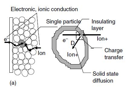
72 Intercalation electrodes can be described by the following equivalent analog Solution resistance Surface films Interfacial charge transfer Solid state diffusion W Intrcalation capacitance

73 Building blocks of equivalent circuits

74 Fuel cell: Equivalent circuit analog
75 Conclusions-1 Impedance is not a physical reality It is an alternating current technique. It is in the frequency domain. It is rigorously generalized concept that contains whole features of an electrochemical system. 75
76 Conclusions-2 In many cases data fitting is not needed. Exact plotting is essential. Graphical analysis is very useful. Experience is needed for data fitting. Anyway, enjoy EIS measurements! It is non-destructive technique. Good to understand your system systematically.
77 The main question: So, What is Electrochemical Impedance Spectroscopy? Probing an electrochemical system with small ac-perturbation over a range of frequencies.
78 Literature 1. Barsukov, E. and Macdonald, J. R Impedance Spectroscopy, 2nd ed. Wiley-Interscience, New York. 2. Conway, B. E Electrochemical Supercapacitors, Kluwer Academic/Plenum, New York. 3. A. Bard and L. Faulkner, Electrochemical Methods. 4. Orazem, M. and Tribollet, B Electrochemical Impedance Spectroscopy (The ECS Series of Texts and Monographs) Wiley-Interscience, New York. 5. Solartron Analytical Frequency Response Analyzer (FRA). Available at AFRAPage.htm. 6. Lectures by Prof. Bernard Boukamp, University of Twente, Dept. of Science &Technology, Enschede, The Netherlands.


79 ..Sunrise in Ein-Gedi, Dead Sea
Electrochemical methods : Fundamentals and Applications
 Electrochemical methods : Fundamentals and Applications Lecture Note 7 May 19, 2014 Kwang Kim Yonsei University kbkim@yonsei.ac.kr 39 8 7 34 53 Y O N Se I 88.91 16.00 14.01 78.96 126.9 Electrochemical
Electrochemical Impedance Spectroscopy (EIS)
") CHEM465/865, 24-3, Lecture 26-28, 19 th Nov., 24 Please, note the following error in the notes lecture19+2 (Hydrodynamic electrodes and Microelectrodes: on page two, 3 rd line, the correct expression for
CHEM465/865, 24-3, Lecture 26-28, 19 th Nov., 24 Please, note the following error in the notes lecture19+2 (Hydrodynamic electrodes and Microelectrodes: on page two, 3 rd line, the correct expression for
Impedance Basics. Fig 1. Generalized current-voltage curve; inset shows the principle of linear approximation for small perturbations.
 Impedance Basics Electrochemical Impedance Spectroscopy (EIS) is a frequency domain measurement made by applying a sinusoidal perturbation, often a voltage, to a system. The impedance at a given frequency
Electrochemical Impedance Spectroscopy
 Electrochemical Impedance Spectroscopy May 2012 Designing the Solution for Electrochemistry Potentiostat/Galvanostat І Battery Cycler І Fuel Cell Test Station +82-2-578-6516 І sales@wonatech.com www.wonatech.com
Basics of Electrochemical Impedance Spectroscopy
 Basics of Electrochemical Impedance Spectroscopy Introduction This document presents an introduction to Electrochemical Impedance Spectroscopy (EIS) theory and has been kept as free from mathematics and
Introduction to EIS (Electrochemical Impedance Spectroscopy) with EC- Lab /EC-Lab Express
 with EC- Lab /EC-Lab Express") Introduction to EIS (Electrochemical Impedance Spectroscopy) with EC- Lab /EC-Lab Express N. Murer, J.-P. Diard 1 /23 OBJECTIVES Understand what is performed during an impedance measurement. Understand
Introduction to EIS (Electrochemical Impedance Spectroscopy) with EC- Lab /EC-Lab Express N. Murer, J.-P. Diard 1 /23 OBJECTIVES Understand what is performed during an impedance measurement. Understand
An Introduction to Electrochemical Impedance Spectroscopy (EIS)
") An Introduction to Electrochemical Impedance Spectroscopy (EIS) Dr. Robert S Rodgers, Ph.D. PO Box 7561 Princeton, NJ 08543 Delivered at June 18, 2009 Meeting of ACS Princeton Local Section Outline A Little
An Introduction to Electrochemical Impedance Spectroscopy (EIS) Dr. Robert S Rodgers, Ph.D. PO Box 7561 Princeton, NJ 08543 Delivered at June 18, 2009 Meeting of ACS Princeton Local Section Outline A Little
VI. EIS STUDIES LEAD NANOPOWDER
 VI. EIS STUDIES LEAD NANOPOWDER 74 26. EIS Studies of Pb nanospheres Impedance (valid for both DC and AC), a complex resistance occurs when current flows through a circuit (composed of various resistors,
Basics of the Kramers-Kronig- and the Z-Hit algorithms Lecture at the Kronach Impedance Days 2015 Dr. Werner Strunz
 Theoretical Aspects for Testing Impedance Data Basics of the Kramers-Kronig- and the Z-Hit algorithms Lecture at the Kronach Impedance Days 215 Dr. Werner Strunz 1 Motivation The entire process of measurement,
161 Electrochemical Impedance Spectroscopy Goals Experimental Apparatus Background Electrochemical impedance spectroscopy
 Goals 161 Electrochemical Impedance Spectroscopy XXGoals To learn the effect of placing capacitors and resistors in series and parallel To model electrochemical impedance spectroscopy data XXExperimental
Werner Strunz, Zahner-elektrik.
 Werner Strunz, Zahner-elektrik www.zahner.de Outline 1. Resistor [ R ] Spannung Strom 0 1 2 3 4 5 6 2 2. Inductance [ L ] Spannung Strom 0 1 2 3 4 5 6 2 3. Capacitor [ C ] Spannung Strom 0 1 2 3 4 5 6
Demystifying Transmission Lines: What are They? Why are They Useful?
 Demystifying Transmission Lines: What are They? Why are They Useful? Purpose of This Note This application note discusses theory and practice of transmission lines. It outlines the necessity of transmission
ELECTROCHEMICAL IMPEDANCE SPECTROSCOPY
 ELECTROCHEMICAL IMPEDANCE SPECTROSCOPY MARK E. ORAZEM University of Florida BERNARD TRIBOLLET Universite Pierre et Marie Curie WILEY A JOHN WILEY & SONS, INC., PUBLICATION Contents Contents Preface Acknowledgments
Electrochemical Impedance Spectroscopy. Part 1: Polarization Resistance: Familiar parameter measured in a new way June 6, 2008
 Electrochemical Impedance Spectroscopy Part 1: Polarization Resistance: Familiar parameter measured in a new way June 6, 2008 Objective The purpose of this lecture series is to generate a set of notes
Electrochemical Impedance Spectroscopy of a LiFePO 4 /Li Half-Cell
 Electrochemical Impedance Spectroscopy of a ifepo 4 /i Half-Cell Mikael Cugnet*, Issam Baghdadi and Marion Perrin French Institute of Solar Energy (INES), CEA / ITEN *Corresponding author: 50 Avenue du
SOFC and Electrolysis Electrochemical Characterisation-Impedance Fundamentals
 SOFC and Electrolysis Electrochemical Characterisation-Impedance Fundamentals Søren Højgaard Jensen Fuel Cells and Solid State Chemistry Division Risø National Laboratory for Sustainable Energy Technical
Gamry Instruments Software Tutorials and Primers
 Gamry Instruments Software Tutorials and Primers Copyright 2005, Gamry Instruments, Inc. All rights reserved. Printed in the USA. Revision 5.0 September 30, 2005 Copyrights and Trademarks Gamry Software
Supporting Information for. Impedance Spectroscopy Characterization of Porous Electrodes. under Different Electrode Thickness Using a Symmetric Cell
 Supporting Information for Impedance Spectroscopy Characterization of Porous Electrodes under Different Electrode Thickness Using a Symmetric Cell for High-Performance Lithium-Ion Batteries Nobuhiro Ogihara,*
Mikaël Cugnet, Issam Baghdadi, and Marion Perrin OCTOBER 10, Excerpt from the Proceedings of the 2012 COMSOL Conference in Milan
 Mikaël Cugnet, Issam Baghdadi, and Marion Perrin OCTOBER 0, 202 Comsol Conference Europe 202, Milan, CEA Italy 0 AVRIL 202 PAGE Excerpt from the Proceedings of the 202 COMSOL Conference in Milan SUMMARY
State-Space Modeling of Electrochemical Processes. Michel Prestat
 State-Space Modeling of Electrochemical Processes Who uses up my battery power? Michel Prestat ETH-Zürich Institute for Nonmetallic Materials Head: Prof. L.J. Gauckler Outline Electrochemistry Electrochemical
Contents. I Background 1. Contents... Preface... Acknowledgments... The Blind Men and the Elephant... xxi. History of Impedance Spectroscopy...
 Contents Contents...................................... Preface....................................... Acknowledgments................................. v xv xix The Blind Men and the Elephant.......................
Understanding Impedance of Li-Ion Batteries with Battery Design Studio
 Understanding Impedance of Li-Ion Batteries with Battery Design Studio Robert Spotnitz Battery Consultant Thursday July 6, 2017 16:40-17:10 Understanding Impedance Li-Ion Batteries with Battery Design
Theoretical Aspects for Testing Impedance Data Basics of the Kramers-Kronig- and the Z-Hit algorithms
 Theoretical Aspects for Testing Impedance Data Basics of the Kramers-Kronig- and the Z-Hit algorithms Lecture at the Kronach Impedance Days 1 Dr. Werner Strunz The validation of experimental impedance
Math reminder for Electrochemists I. The simplicity of complex number and impedance diagrams
 Math reminder for Electrochemists I. The simplicity of complex number and impedance diagrams I Introduction The results of impedance measurements are complex numbers. The electrochemists are sometimes
Performance analysis of Lithium-ion-batteries: status and prospects
 Performance analysis of Lithium-ion-batteries: status and prospects DPG conference Erlangen March 218 Ellen Ivers-Tiffée, Philipp Braun, Michael Weiss Karlsruhe Institute of Technology (KIT), Germany KIT
The Apparent Constant-Phase-Element Behavior of a Disk Electrode with Faradaic Reactions
 Journal of The Electrochemical Society, 154 2 C99-C107 2007 0013-4651/2006/1542/C99/9/$20.00 The Electrochemical Society The Apparent Constant-Phase-Element Behavior of a Disk Electrode with Faradaic Reactions
Capacity fade studies of Lithium Ion cells
 Capacity fade studies of Lithium Ion cells by Branko N. Popov, P.Ramadass, Bala S. Haran, Ralph E. White Center for Electrochemical Engineering, Department of Chemical Engineering, University of South
Advanced Lab Course. Impedance Spectroscopy 1 INTRODUCTION 1 2 BASIC CONCEPTS What is impedance FFT-Impedance Measurements 4
 Advanced Lab Course Impedance Spectroscopy M208 As of: 2015-04-01 Aim: In situ characterization of electrochemical systems Content 1 INTRODUCTION 1 2 BASIC CONCEPTS 1 2.1 What is impedance 1 2.2 FFT-Impedance
DISTRIBUTED TIME-CONSTANT IMPEDANCE RESPONSES INTERPRETED IN TERMS OF PHYSICALLY MEANINGFUL PROPERTIES
 DISTRIBUTED TIME-CONSTANT IMPEDANCE RESPONSES INTERPRETED IN TERMS OF PHYSICALLY MEANINGFUL PROPERTIES By BRYAN D. HIRSCHORN A DISSERTATION PRESENTED TO THE GRADUATE SCHOOL OF THE UNIVERSITY OF FLORIDA
PHYSICS 171 UNIVERSITY PHYSICS LAB II. Experiment 6. Transient Response of An RC Circuit
 PHYSICS 171 UNIVERSITY PHYSICS LAB II Experiment 6 Transient Response of An RC Circuit Equipment: Supplies: Function Generator, Dual Trace Oscilloscope.002 Microfarad, 0.1 Microfarad capacitors; 1 Kilohm,
Electrical Circuits Lab Series RC Circuit Phasor Diagram
 Electrical Circuits Lab. 0903219 Series RC Circuit Phasor Diagram - Simple steps to draw phasor diagram of a series RC circuit without memorizing: * Start with the quantity (voltage or current) that is
Role of Cobalt Iron (Oxy)Hydroxide (CoFeO x ) as Oxygen Evolution Catalyst on Hematite Photoanodes
Hydroxide (CoFeO x ) as Oxygen Evolution Catalyst on Hematite Photoanodes") Electronic Supplementary Material (ESI) for Energy & Environmental Science. This journal is The Royal Society of Chemistry 2018 Supporting Information Role of Cobalt Iron (Oxy)Hydroxide (CoFeO x ) as Oxygen
Electronic Supplementary Material (ESI) for Energy & Environmental Science. This journal is The Royal Society of Chemistry 2018 Supporting Information Role of Cobalt Iron (Oxy)Hydroxide (CoFeO x ) as Oxygen
ELECTROCHEMICAL IMPEDANCE ANALYSIS OF LITHIUM COBALT OXIDE BATTERIES
 ELECTROCHEMICAL IMPEDANCE ANALYSIS OF LITHIUM COBALT OXIDE BATTERIES By SALIM EROL A THESIS PRESENTED TO THE GRADUATE SCHOOL OF THE UNIVERSITY OF FLORIDA IN PARTIAL FULFILLMENT OF THE REQUIREMENTS FOR
Solutions to these tests are available online in some places (but not all explanations are good)...
...") The Physics GRE Sample test put out by ETS https://www.ets.org/s/gre/pdf/practice_book_physics.pdf OSU physics website has lots of tips, and 4 additional tests http://www.physics.ohiostate.edu/undergrad/ugs_gre.php
The Physics GRE Sample test put out by ETS https://www.ets.org/s/gre/pdf/practice_book_physics.pdf OSU physics website has lots of tips, and 4 additional tests http://www.physics.ohiostate.edu/undergrad/ugs_gre.php
The effects of polar excipients transcutol and dexpanthenol on molecular mobility, permeability, and electrical impedance of the skin barrier
 Supplementary Material The effects of polar excipients transcutol and dexpanthenol on molecular mobility, permeability, and electrical impedance of the skin barrier Sebastian Björklund a,b, *, Quoc Dat
and constant current operations in capacitive deionization
 Energy consumption analysis of constant voltage and constant current operations in capacitive deionization Supporting information Yatian Qu, a,b Patrick G. Campbell, b Lei Gu, c Jennifer M. Knipe, b Ella
Electrochemical Kinetic Studies of Li-Ion in O2-Structured
 0013-4651/2002/150 1 /A1/13/$7.00 The Electrochemical Society, Inc. Electrochemical Kinetic Studies of Li-Ion in O2-Structured Li 2Õ3 Ni 1Õ3 Mn 2Õ3 O 2 and Li 2Õ3 x Ni 1Õ3 Mn 2Õ3 O 2 by EIS and GITT K.
Development of a Battery Energy Loss Observer Based on Improved Equivalent Circuit Modelling
 Development of a Battery Energy Loss Observer Based on Improved Equivalent Circuit Modelling Ahmed M. Fares 1,2, Christian Klumpner 1, Mark Sumner 1 1 UNIVERSITY OF NOTTINGHAM, Nottingham NG7 2RD, United
Electrodeposited nickel hydroxide on nickel foam with ultrahigh. capacitance
 Electrodeposited nickel hydroxide on nickel foam with ultrahigh capacitance Guang-Wu Yang, Cai-Ling Xu* and Hu-Lin Li* College of Chemistry and Chemical Engineering, Lanzhou University, 73 (PR China) 1.
Sinusoids and Phasors
 CHAPTER 9 Sinusoids and Phasors We now begins the analysis of circuits in which the voltage or current sources are time-varying. In this chapter, we are particularly interested in sinusoidally time-varying
EIS of Organic Coatings and Paints
 EIS of Organic Coatings and Paints Introduction All My Impedance Spectra Look the Same! "I m an experienced polymer chemist. I m trying to use Electrochemical Impedance Spectroscopy (EIS) to predict the
18 - ELECTROMAGNETIC INDUCTION AND ALTERNATING CURRENTS ( Answers at the end of all questions ) Page 1
 Page 1") ( Answers at the end of all questions ) Page ) The self inductance of the motor of an electric fan is 0 H. In order to impart maximum power at 50 Hz, it should be connected to a capacitance of 8 µ F (
( Answers at the end of all questions ) Page ) The self inductance of the motor of an electric fan is 0 H. In order to impart maximum power at 50 Hz, it should be connected to a capacitance of 8 µ F (
470 Lecture #7 of 18
 Lecture #7 of 18 470 471 Q: What s in this set of lectures? A: Introduction, Review, and B&F Chapter 1, 15 & 4 main concepts: Section 1.1: Redox reactions Chapter 15: Electrochemical instrumentation Section
Relaxation Impedance
 Relaxation Impedance One Reason for Inductive and Capacitive Behavior in Low Frequency Impedance Spectra of Corroding Electrodes, Batteries and Fuel Cells C.A. Schiller a, F. Richter a,, W. Strunz a, N.
INFLUENCE OF ELECTRODE GEOMETRY ON LOCAL AND GLOBAL IMPEDANCE RESPONSE
 INFLUENCE OF ELECTRODE GEOMETRY ON LOCAL AND GLOBAL IMPEDANCE RESPONSE By SHAO-LING WU A DISSERTATION PRESENTED TO THE GRADUATE SCHOOL OF THE UNIVERSITY OF FLORIDA IN PARTIAL FULFILLMENT OF THE REQUIREMENTS
Annexure-I. network acts as a buffer in matching the impedance of the plasma reactor to that of the RF
 Annexure-I Impedance matching and Smith chart The output impedance of the RF generator is 50 ohms. The impedance matching network acts as a buffer in matching the impedance of the plasma reactor to that
Note 11: Alternating Current (AC) Circuits
 Circuits") Note 11: Alternating Current (AC) Circuits V R No phase difference between the voltage difference and the current and max For alternating voltage Vmax sin t, the resistor current is ir sin t. the instantaneous
Note 11: Alternating Current (AC) Circuits V R No phase difference between the voltage difference and the current and max For alternating voltage Vmax sin t, the resistor current is ir sin t. the instantaneous
Capacitive properties of a gold/electrolyte interface
 Capacitive properties of a gold/electrolyte interface Lab Course Manual Physik E19 (AG Krischer), Technische Universität München Abstract When metals are brought together with electrolytes, many interesting
SUPPLEMENTARY INFORMATION
 doi:10.1038/nature17653 Supplementary Methods Electronic transport mechanism in H-SNO In pristine RNO, pronounced electron-phonon interaction results in polaron formation that dominates the electronic
Studies of the first lithiation of graphite materials by. by electrochemical impedance spectroscopy ARTICLES
 Chinese Science Bulletin 2006 Vol. 51 No. 9 1055 1059 DOI: 10.1007/s11434-006-1055-y Studies of the first lithiation of graphite materials by electrochemical impedance spectroscopy ZHUANG Quanchao 1,3,
Potentiodynamic electrochemical impedance spectroscopy for solid state chemistry. G. A. Ragoisha and A. S. Bondarenko
 Preprint from Solid State Phenomena V.90-91(2003) (Proceedings of Solid State Chemistry 2002) Potentiodynamic electrochemical impedance spectroscopy for solid state chemistry G. A. Ragoisha and A. S. Bondarenko
239 Lecture #4 of 18
 Lecture #4 of 18 239 240 Q: What s in this set of lectures? A: Introduction, Review, and B&F Chapter 1, 15 & 4 main concepts: Section 1.1: Redox reactions Chapter 15: Electrochemical instrumentation Section
Some of the different forms of a signal, obtained by transformations, are shown in the figure. jwt e z. jwt z e
 Transform methods Some of the different forms of a signal, obtained by transformations, are shown in the figure. X(s) X(t) L - L F - F jw s s jw X(jw) X*(t) F - F X*(jw) jwt e z jwt z e X(nT) Z - Z X(z)
Chapter 10: Sinusoids and Phasors
 Chapter 10: Sinusoids and Phasors 1. Motivation 2. Sinusoid Features 3. Phasors 4. Phasor Relationships for Circuit Elements 5. Impedance and Admittance 6. Kirchhoff s Laws in the Frequency Domain 7. Impedance
Microwave Oscillators Design
 Microwave Oscillators Design Oscillators Classification Feedback Oscillators β Α Oscillation Condition: Gloop = A β(jω 0 ) = 1 Gloop(jω 0 ) = 1, Gloop(jω 0 )=2nπ Negative resistance oscillators Most used
Jorge García-Cañadas
 Thermoelectric Network Workshop - oughborough University, 14 th April 15 - Measurement of thermoelectric properties by means of impedance spectroscopy Jorge García-Cañadas Cardiff School of Engineering
Supporting Information. 13 Pages, 9 Figures. Mechanisms of Humic Acid Fouling on Capacitive and Insertion Electrodes for Electrochemical Desalination
 Supporting Information 13 Pages, 9 Figures Mechanisms of Humic Acid Fouling on Capacitive and Insertion Electrodes for Electrochemical Desalination Xitong Liu, 1 Jay F. Whitacre, 2,3,4 and Meagan S. Mauter
Modeling charge polarization voltage for large lithium-ion batteries in electric vehicles
 Journal of Industrial Engineeringand Management JIEM, 2013 6(2): 686-697 Online ISSN: 2013-0953 Print ISSN: 2013-8423 http://dx.doi.org/10.3926/jiem.895 Modeling charge polarization voltage for large lithium-ion
EXP. NO. 3 Power on (resistive inductive & capacitive) load Series connection
 load Series connection") OBJECT: To examine the power distribution on (R, L, C) series circuit. APPARATUS 1-signal function generator 2- Oscilloscope, A.V.O meter 3- Resisters & inductor &capacitor THEORY the following form for
OBJECT: To examine the power distribution on (R, L, C) series circuit. APPARATUS 1-signal function generator 2- Oscilloscope, A.V.O meter 3- Resisters & inductor &capacitor THEORY the following form for
Towards selective test protocols for accelerated in situ degradation of PEM electrolysis cell components
 Towards selective test protocols for accelerated in situ degradation of PEM electrolysis cell components 1 st International Conference on Electrolysis - Copenhagen Thomas Lickert, Claudia Schwarz, Patricia
Electromagnetic Oscillations and Alternating Current. 1. Electromagnetic oscillations and LC circuit 2. Alternating Current 3.
 Electromagnetic Oscillations and Alternating Current 1. Electromagnetic oscillations and LC circuit 2. Alternating Current 3. RLC circuit in AC 1 RL and RC circuits RL RC Charging Discharging I = emf R
Carbon-based nanocomposite EDLC supercapacitors
 Carbon-based nanocomposite EDLC supercapacitors C. Lei and C. Lekakou Faculty of Engineering and Physical Sciences, University of Surrey, Guildford, Surrey GU2 7XH, UK, C.Lekakou@surrey.ac.uk ABSTRACT
Polymer graphite composite anodes for Li-ion batteries
 Polymer graphite composite anodes for Li-ion batteries Basker Veeraraghavan, Bala Haran, Ralph White and Branko Popov University of South Carolina, Columbia, SC 29208 Plamen Atanassov University of New
A 2. The potential difference across the capacitor is F m N m /C m. R R m m R m R m 0
 30.53. Model: The charged metal spheres are isolated and far from each other and anything else. Solve: (a) The charge on a sphere of radius r, charged to a potential V 0 is given by the equations: The
CIRCUIT ANALYSIS II. (AC Circuits)
") Will Moore MT & MT CIRCUIT ANALYSIS II (AC Circuits) Syllabus Complex impedance, power factor, frequency response of AC networks including Bode diagrams, second-order and resonant circuits, damping and
Will Moore MT & MT CIRCUIT ANALYSIS II (AC Circuits) Syllabus Complex impedance, power factor, frequency response of AC networks including Bode diagrams, second-order and resonant circuits, damping and
Lecture 6: Impedance (frequency dependent. resistance in the s- world), Admittance (frequency. dependent conductance in the s- world), and
, Admittance (frequency. dependent conductance in the s- world), and") Lecture 6: Impedance (frequency dependent resistance in the s- world), Admittance (frequency dependent conductance in the s- world), and Consequences Thereof. Professor Ray, what s an impedance? Answers:
Lecture 6: Impedance (frequency dependent resistance in the s- world), Admittance (frequency dependent conductance in the s- world), and Consequences Thereof. Professor Ray, what s an impedance? Answers:
Unique Behaviour of Nonsolvents for Polysulphides in Lithium-Sulphur Batteries.
 Electronic Supplementary Material (ESI) for Energy & Environmental Science. This journal is The Royal Society of Chemistry 214 Supplementary Information Unique Behaviour of Nonsolvents for Polysulphides
Tutorial 2-2 part2. Batteries for electric and hybrid vehicles. State of the art, Modeling, Testing, Aging
 Tutorial 2-2 part2 Batteries for electric and hybrid vehicles State of the art, Modeling, Testing, Aging serge.pelissier@inrets.fr Modeling of batteries : outline Batteries modeling : introduction Electric
Electric Circuit Theory
 Electric Circuit Theory Nam Ki Min nkmin@korea.ac.kr 010-9419-2320 Chapter 11 Sinusoidal Steady-State Analysis Nam Ki Min nkmin@korea.ac.kr 010-9419-2320 Contents and Objectives 3 Chapter Contents 11.1
LINEAR CIRCUIT ANALYSIS (EED) U.E.T. TAXILA 09
 U.E.T. TAXILA 09") LINEAR CIRCUIT ANALYSIS (EED) U.E.T. TAXILA 09 ENGR. M. MANSOOR ASHRAF INTRODUCTION Thus far our analysis has been restricted for the most part to dc circuits: those circuits excited by constant or time-invariant
LINEAR CIRCUIT ANALYSIS (EED) U.E.T. TAXILA 09 ENGR. M. MANSOOR ASHRAF INTRODUCTION Thus far our analysis has been restricted for the most part to dc circuits: those circuits excited by constant or time-invariant
Chapter 10: Sinusoidal Steady-State Analysis
 Chapter 10: Sinusoidal Steady-State Analysis 1 Objectives : sinusoidal functions Impedance use phasors to determine the forced response of a circuit subjected to sinusoidal excitation Apply techniques
Comparison of the Degradation of the Polarization Resistance of Symmetrical LSM-YSZ Cells with Anode Supported Ni-YSZ/YSZ/LSM-YSZ SOFCs
 489 10.1149/1.3205559 The Electrochemical Society Comparison of the Degradation of the Polarization Resistance of Symmetrical LSM-YSZ Cells with Anode Supported Ni-YSZ/YSZ/LSM-YSZ SOFCs I. M. Torres da
Redox additive Aqueous Polymer-gel Electrolyte for Electric Double Layer Capacitor
 Electronic Supplementary Information Redox additive Aqueous Polymer-gel Electrolyte for Electric Double Layer Capacitor S.T. Senthilkumar, a R. Kalai Selvan,* a N.Ponpandian b and J.S. Melo c a Solid State
Assessment Schedule 2016 Physics: Demonstrate understanding electrical systems (91526)
") NCEA evel 3 Physics (91526) 2016 page 1 of 5 Assessment Schedule 2016 Physics: Demonstrate understanding electrical systems (91526) Evidence Statement NØ N1 N 2 A 3 A 4 M 5 M 6 E 7 E 8 0 1A 2A 3A 4A or
NCEA evel 3 Physics (91526) 2016 page 1 of 5 Assessment Schedule 2016 Physics: Demonstrate understanding electrical systems (91526) Evidence Statement NØ N1 N 2 A 3 A 4 M 5 M 6 E 7 E 8 0 1A 2A 3A 4A or
Inductors. Hydraulic analogy Duality with capacitor Charging and discharging. Lecture 12: Inductors
 Lecture 12: nductors nductors Hydraulic analogy Duality with capacitor Charging and discharging Robert R. McLeod, University of Colorado http://hilaroad.com/camp/projects/magnet.html 99 Lecture 12: nductors
Aalborg Universitet. Published in: Proceedings of the 2014 Energy Conversion Congress and Exposition (ECCE)
") Aalborg Universitet Diagnosis of Lithium-Ion Batteries State-of-Health based on Electrochemical Impedance Spectroscopy Technique Stroe, Daniel-Ioan; Swierczynski, Maciej Jozef; Stroe, Ana-Irina; Knap,
Aalborg Universitet Diagnosis of Lithium-Ion Batteries State-of-Health based on Electrochemical Impedance Spectroscopy Technique Stroe, Daniel-Ioan; Swierczynski, Maciej Jozef; Stroe, Ana-Irina; Knap,
2. The following diagram illustrates that voltage represents what physical dimension?
 BioE 1310 - Exam 1 2/20/2018 Answer Sheet - Correct answer is A for all questions 1. A particular voltage divider with 10 V across it consists of two resistors in series. One resistor is 7 KΩ and the other
Experimental Methods of Electrochemistry a.c. impedance spectroscopy
 Experimental Methods of Electrochemistry a.c. impedance spectroscopy Introduction Application of a small perturbation phase difference & amplitude (i.e. the impedance) electrode process: diffusion, kinetics,
Louisiana State University Physics 2102, Exam 2, March 5th, 2009.
 PRINT Your Name: Instructor: Louisiana State University Physics 2102, Exam 2, March 5th, 2009. Please be sure to PRINT your name and class instructor above. The test consists of 4 questions (multiple choice),
SIMULATION-BASED development methods are increasingly
 742 IEEE TRANSACTIONS ON INDUSTRY APPLICATIONS, VOL. 41, NO. 3, MAY/JUNE 2005 Impedance-Based Simulation Models of Supercapacitors and Li-Ion Batteries for Power Electronic Applications Stephan Buller,
EE292: Fundamentals of ECE
 EE292: Fundamentals of ECE Fall 2012 TTh 10:00-11:15 SEB 1242 Lecture 20 121101 http://www.ee.unlv.edu/~b1morris/ee292/ 2 Outline Chapters 1-3 Circuit Analysis Techniques Chapter 10 Diodes Ideal Model
Lecture 23: NorCal 40A Power Amplifier. Thermal Modeling.
 Whites, EE 322 Lecture 23 Page 1 of 13 Lecture 23: NorCal 40A Power Amplifier. Thermal Modeling. Recall from the last lecture that the NorCal 40A uses a Class C power amplifier. From Fig. 10.3(b) the collector
The Global and Local Impedance Response of a Blocking Disk Electrode with Local Constant-Phase-Element Behavior
 Journal of The Electrochemical Society, 154 2 C89-C98 2007 0013-4651/2006/1542/C89/10/$20.00 The Electrochemical Society The Global and Local Impedance Response of a Blocking Disk Electrode with Local
Supporting Information. Electrochemical Raman Spectroscopy Investigation
 Supporting Information High-Capacitance Mechanism for Ti 3 C 2 T x MXene by In Situ Electrochemical Raman Spectroscopy Investigation Minmin Hu,, Zhaojin Li,, Tao Hu,, Shihao Zhu,, Chao Zhang and Xiaohui
Photovoltaic Characterizations: Polarization and Mott Schottky plot
 Application note #4 Photovoltaic Characterizations: Polarization and Mott Schottky plot I- Introduction With the greenhouse effect and the increase of the price of the energy, new ways to produce energy
The Mechanism of Electropolishing of Nb in Hydrofluoric-Sulfuric Acid (HF+H 2 SO 4 ) Electrolyte
 Electrolyte") The Mechanism of Electropolishing of Nb in Hydrofluoric-Sulfuric Acid (HF+H 2 SO 4 ) Electrolyte Hui Tian *+, Charles E. Reece +, Michael J. Kelley *+ Applied Science Department, College of William and
The Mechanism of Electropolishing of Nb in Hydrofluoric-Sulfuric Acid (HF+H 2 SO 4 ) Electrolyte Hui Tian *+, Charles E. Reece +, Michael J. Kelley *+ Applied Science Department, College of William and
EE100Su08 Lecture #11 (July 21 st 2008)
") EE100Su08 Lecture #11 (July 21 st 2008) Bureaucratic Stuff Lecture videos should be up by tonight HW #2: Pick up from office hours today, will leave them in lab. REGRADE DEADLINE: Monday, July 28 th 2008,
EE100Su08 Lecture #11 (July 21 st 2008) Bureaucratic Stuff Lecture videos should be up by tonight HW #2: Pick up from office hours today, will leave them in lab. REGRADE DEADLINE: Monday, July 28 th 2008,
On the Error Structure of Impedance Measurements
 Journal of The Electrochemical Society, 150 10 E477-E490 003 0013-4651/003/150 10 /E477/14/$7.00 The Electrochemical Society, Inc. On the Error Structure of Impedance Measurements Simulation of FRA Instrumentation
Investigating Grain Boundaries in BaCuS 1-x Se x F Using Impedance Spectroscopy. Author: Briony Horgan Physics Department Oregon State University
 Investigating Grain Boundaries in BaCuS 1-x Se x F Using Impedance Spectroscopy Author: Briony Horgan Physics Department Oregon State University Advisor: Dr. Janet Tate Physics Department Oregon State
1 Phasors and Alternating Currents
 Physics 4 Chapter : Alternating Current 0/5 Phasors and Alternating Currents alternating current: current that varies sinusoidally with time ac source: any device that supplies a sinusoidally varying potential
(amperes) = (coulombs) (3.1) (seconds) Time varying current. (volts) =
 = (coulombs) (3.1) (seconds) Time varying current. (volts) =") 3 Electrical Circuits 3. Basic Concepts Electric charge coulomb of negative change contains 624 0 8 electrons. Current ampere is a steady flow of coulomb of change pass a given point in a conductor in
3 Electrical Circuits 3. Basic Concepts Electric charge coulomb of negative change contains 624 0 8 electrons. Current ampere is a steady flow of coulomb of change pass a given point in a conductor in
Numerical investigations of solution resistance effects on nonlinear electrochemical impedance spectra
 Numerical investigations of solution resistance effects on nonlinear electrochemical impedance spectra Authors: Sruthi Santhanam a, Vimala Ramani b, Ramanathan Srinivasan c* Address: a Department of Chemical
Chapter 28 Solutions
 Chapter 8 Solutions 8.1 (a) P ( V) R becomes 0.0 W (11.6 V) R so R 6.73 Ω (b) V IR so 11.6 V I (6.73 Ω) and I 1.7 A ε IR + Ir so 15.0 V 11.6 V + (1.7 A)r r 1.97 Ω Figure for Goal Solution Goal Solution
2006 #3 10. a. On the diagram of the loop below, indicate the directions of the magnetic forces, if any, that act on each side of the loop.
 1992 1 1994 2 3 3 1984 4 1991 5 1987 6 1980 8 7 9 2006 #3 10 1985 2006E3. A loop of wire of width w and height h contains a switch and a battery and is connected to a spring of force constant k, as shown
SUGGESTED LESSON PLANS FOR PHY 097 SEMESTER NOV10 Text Book : PHYSICS FOR SCIENTISTS & ENGINEERS WITH MODERN PHYSICS BY GIANCOLI, FOURTH EDITION
 SUGGESTED LESSON PLANS FOR PHY 097 SEMESTER NOV0 Text Book : PHYSICS FOR SCIENTISTS & ENGINEERS WITH MODERN PHYSICS BY GIANCOLI, FOURTH EDITION Week Topics Section Page Hrs Sub-Topics WAVES AND OPTICS,.0
Sinusoidal Steady-State Analysis
 Sinusoidal Steady-State Analysis Almost all electrical systems, whether signal or power, operate with alternating currents and voltages. We have seen that when any circuit is disturbed (switched on or
Graphical Estimation of Interfacial Capacitance of PEM Fuel Cells from Impedance Measurements
 0013-4651/2008/156 2 /B203/7/$23.00 The Electrochemical Society Graphical Estimation of Interfacial Capacitance of PEM Fuel Cells from Impedance Measurements Sunil K. Roy* and Mark E. Orazem**,z Department
Staircase Potentio Electrochemical Impedance Spectroscopy and automatic successive ZFit analysis
 Application note #18 Staircase Potentio Electrochemical Impedance Spectroscopy and automatic successive ZFit analysis I- Introduction It is sometimes useful to automate measurements. With EC-Lab and EC-Lab
Experiment 3: Resonance in LRC Circuits Driven by Alternating Current
 Experiment 3: Resonance in LRC Circuits Driven by Alternating Current Introduction In last week s laboratory you examined the LRC circuit when constant voltage was applied to it. During this laboratory
Assessment Schedule 2015 Physics: Demonstrate understanding of electrical systems (91526)
") NCEA Level 3 Physics (91526) 2015 page 1 of 6 Assessment Schedule 2015 Physics: Demonstrate understanding of electrical systems (91526) Evidence Q Evidence Achievement Achievement with Merit Achievement
NCEA Level 3 Physics (91526) 2015 page 1 of 6 Assessment Schedule 2015 Physics: Demonstrate understanding of electrical systems (91526) Evidence Q Evidence Achievement Achievement with Merit Achievement