ELECTROMAGNETIC DESIGN AND FEM ANALYSIS OF A NOVEL DUAL-AIR-GAP RELUCTANCE MACHINE
|
|
|
- Leona Marsh
- 5 years ago
- Views:
Transcription
1 Progress In Electromagnetics Research, Vol. 140, , 2013 ELECTROMAGNETIC DESIGN AND FEM ANALYSIS OF A NOVEL DUAL-AIR-GAP RELUCTANCE MACHINE Chockalingam Aravind Vaithilingam 3, *, Norhisam Misron 1, 2, Ishak Aris 1, Mohammad Hamiruce Marhaban 1, and Masami Nirei 4 1 Department of Electrical and Electronics, University Putra Malaysia, Selangor, Malaysia 2 Institute of Advanced Technology (ITMA), Universiti Putra Malaysia, Serdang, Selangor 43400, Malaysia 3 School of Engineering, Taylor s University, Selangor, Malaysia 4 Nagona College of Technology, Japan Abstract The electro-magnetic torque production in the reluctance machine is highly influenced by the magnetic linkages in the air-gap area. The conventional machines derive the drawback of reduction in the air-gap area to a minimal due to influence of mechanical unbalancing thereby restricting the effective energy conversion area. In order to increase the magnetic linkage area, the dual-air-gap structure is introduced. The dual-air-gap structure is realised through the division of the magnetic circuit area into two air-gaps while still maintaining the net air-gap length value. A double-rotor with singlestator structure is used to attribute the above concept. The electromagnetic analysis of such a structure is developed and investigated through numerical analysis. In order to validate the proposed structure the electro-magnetic characteristics are compared with that of the conventional structure at similar operating conditions. The maximum torque generated by the selected dual-air-gap structure is Nm and for conventional structure is Nm. The evaluation of the proposed machine is done at the same operating conditions and it is found that the dual-air-gap structure exhibit 65% increase in average torque value in comparison with that of the conventional single-air-gap structure. Received 20 February 2013, Accepted 31 May 2013, Scheduled 19 June 2013 * Corresponding author: Chockalingam Aravind Vaithilingam (aravindcv@ieee.org).
2 524 Vaithilingam et al. 1. INTRODUCTION With its simple structure, absence of winding in rotor side, fault tolerant capability, low cost with no permanent magnet either in the stator or in the rotor, reluctance machine is a better choice of motor under adverse conditions [1]. The torque production in reluctance motor is derived from the tendency of the non-magnetic rotor poles tending to align with that of the nearest excited stator poles [2]. With the corresponding stator coil excitations, the rotor experiences a force that pulls the rotor from the full non-overlap position to the full overlap position. The traverse of this pull is influenced by the swept angle (called as pole-arc) between the poles. The flux linkage area determines the permeance (inverse of reluctance) in the magnetic circuit and thereby the torque producing capability. In order to increase the flux linkage area, a dual-air-gap structure is proposed through the doublerotor structure [3]. The early concepts of introduction of doublestator or rotor structure are finding new dimensions in developing high power density machines. The double-stator structure is extensively progressive in applications related to the development of the permanent magnet brush-less machines [4 6]. The application of the use of doublestator for wind energy application is presented in [7]. Two stators for the bearing-less reluctance type of machine are put forward in [8]. The double-stator structure increases the coil spacing however it increases the volume and also increases the losses inside the machine. On the contrary to the double-stator structure, the double-rotor structure is researched mostly based on the application requirements. Double-rotor motor feasibility is proposed in [9] as applied to the deployment in hybrid electric vehicle. In electric vehicle development where the two wheels are need to be connected for differential action is proposed in [10]. The electro-magnetic design and analysis of double-rotor flux modulated permanent magnet machines is put forward in [11]. The dual-layer rotor reluctance generator is presented in [12] using finite element analysis. The double-rotor structure with independent operation of the two rotors using simulation is presented in [13]. In this research the double-rotor single-stator structure to realise the dual-air-gap, as confined with the name as Double Rotor Reluctance Motor (DRRM) is investigated. Section 2 presents the features of the inductance profile of the machine and its influence in the torque generation. Section 3 presents the design aspects in the dual-air-gap structure used in this design. Section 4 presents the electromagnetic analysis through finite element tool. Section 5 presents a comparative evaluations of the proposed structure with that of the conventional structure.
3 Progress In Electromagnetics Research, Vol. 140, INDUCTANCE PROFILE Figure 1 shows the rotor moving for one pole pitch from the full nonoverlap position to full overlap position and back to full non-overlap position for a typical reluctance machine. β s and β r represent excited stator pole and rotor pole-arc, respectively. As can be seen at both the extreme positions (at full overlap and full non-overlap positions), no useful energy is converted rather is stored inside the machine as field energy. The useful output torque is developed only as the rotor roll over the stator. As the machine is moving from the full non-overlap position to the full overlap position, the motoring torque (Figure 1(a) Figure 1(e)) is developed, and during the energy released as the rotor is moving away from the full overlap position to the full non-overlap positions the generating torque (Figure 1(e) Figure 1(i)) is developed. Table 1 shows the properties at the extreme positions of the rotor (a) (b) (c) (d) (e) (f) (g) (h) (i) Figure 1. Motoring and generating mode. (a) Full non-overlap, (b) 1/4th of poles interact, (c) 1/2th of poles interact, (d) 3/4th of poles interact, (e) full overlap, (f) 3/4th of poles interact, (g) 1/2th of poles interact, (h) 1/4th of poles interact, (i) full non-overlap. Table 1. Properties of full non-overlap and full overlap position. Property Full Non-overlap Full Overlap Position angle ±90 0, 180 Inductance value Minimum Maximum Saturation unlikely most likely Torque zero zero Equilibrium unstable stable
4 526 Vaithilingam et al. movement. As can be seen, during the full non-overlap position, the machine is stable; however the core tends to saturate rapidly during the full overlap position, the equilibrium is not realized. The range of operation of the two extreme positions influence the torque generating capability to a larger extent and hence it is expected the rotor to spend less time in both the extreme positions. As the rotor traverses (depends on the pole arc values of the stator and the rotor) between the extreme positions, the flux linkage area is increased and thereby improving the torque generating capability. Figure 2. Inductance profile. Figure 2 represents the ideal inductance characteristics for motoring conditions (θ 1 and θ 2 ) and for the generating conditions (θ 3 and θ 4 ). For the motoring conditions, the torque equation is as in Equation (1). ( ) 1 (i 2 T e = ) [ ] L a L u (1) 2 where L a is the completely overlap inductance and L u the completely non-overlap positions. The instantaneous torque developed can be written as in Equation (2). [ ] [ ] (i) 2 dl(φ) T e = (2) 2β s dθ But the inductance L is proportional to the permeance P at the point of contact and given as in Equation (3). β s L = N 2 P (3) where N is the number of turns. Hence the above equation can be written as in Equation (4). [ ] [ ] (i N) 2 dp (φ) T e = (4) 2β s dθ
5 Progress In Electromagnetics Research, Vol. 140, The permeance variation term introduces the structural characteristics that depends on the flux linkage contact area as in Equation (5). P = µ A g l g (5) where A g defines the swept pole face area (pole-arcs), and l g represents the radial length of the air-gap. This pole swept area depends on the pole-arc of the stator and the rotor that is involved during the energy conversion cycle of the machine. For the impressed current, the magnetic flux is the product of the magnetic flux density B g and air-gap area A g. Therefore, the electromagnetic torque is given as in Equation (6). [ (Bg A g N) 2 ] [ ] dp (φ) T e = (6) 2β s dθ In generic form the swept area during the motoring condition is given as in Equation (7). A g = (β s )(D s )L stk (7) where L stk is the stack length, D s the diameter of the stator, with the assumption that the stator pole-arc value is greater than the rotor pole-arc value. 3. CONCEPT OF DUAL-AIR-GAP STRUCTURE 3.1. Design Concepts Figure 3 shows the magnetic circuit for the long flux flow in the conventional reluctance machines. As can be seen with the excited stator pole the flux traverses through the upper air-gap (l g1 ) and Figure 3. Conventional reluctance machine magnetic circuit.
6 528 Vaithilingam et al. through the lower air-gap (l g2 ) to complete the magnetic circuit. The air-gap length in the conventional reluctance motor is restricted to a minimal value as it introduces mechanical imbalance during operation. This affects the torque producing capability of the machine. Secondly, the area of flux linkages as the rotor moves over the stator is influenced by the extent of pole-arc as the flux traverse in the air-gap. The extension of the division in the air-gap length is derived with the introduction of the dual-air-gap with still maintaining the net airgap length thereby maximising the air-gap surface area. This dualair-gap necessitates the modification in the machine structure either through double rotors with single stator or through double stators with single rotor. In brush-less DC machines, it is a common trend to use configurations of double stators for maximising the net magneto-motive force. However, the double-stator structure leads to the increase in the number of turns and hence the loss inside the machine. The reluctance value at the air-gap is given as in Equations (8), (9). R lg1 = µ 0 (β s )(D s )(L stk ) (8) R lg2 = l g2 µ 0 (β s )(D s )(L stk ) (9) Therefore, the net reluctance R lg value in the air-gap is given as in Equation (10). 2l g R lg = µ 0 (β s )(D s )(L stk ) (10) where l g1 l g = l g1 + l g2 ; R lg = R lg1 + R lg2 (11) Therefore, the flux linked is given by Equation (12). φ = (Ni)µ 0(β s )(D s )(L stk ) 2l g (12) Figure 4 shows the magnetic circuit for a typical double-rotor structure and the magnetic circuit (the net air-gap length is still maintained). As can be seen, the air-gap length is divided, and hence the reluctance at each of the air-gap is reduced by half as in the Equations (13), (14). R lg1 = 2µ 0 (β os )(D os )L stk (13) R lg2 = l g2 2µ 0 (β is )(D is )L stk (14) The reluctance value is given as l g1 R lg = 2(R lg1 + R lg2 ) (15)
7 - Progress In Electromagnetics Research, Vol. 140, Figure 4. Proposed double-rotor reluctance machine magnetic circuit. Therefore, the flux linked is given as in Equation (16) β os β is D is D os φ = (NiL stk µ 0 ) (16) l g1 β is D is + l g2 β os D os The length of the air-gap needs to be kept at the same value for symmetric rotation about the center l g1 = l g2, then the flux linked is given as in Equation (17). φ = NiL stkµ 0 l g β os β is D is D os β is D is + β os D os (17) The flux linkage depends on the pole arc interactions values as the physical dimension is fixed for the machine. This analysis is done based on the assumption that the stator pole-arc is bigger than the rotor to establish the relation of the flux linked to that of the polearc. However, this analysis can be extended for the case of the rotor pole-arc bigger than the stator pole-arc, in which case the self-starting capability at any point is difficult Limitations on Pole-arc Values The design considered in this analysis is of 6 stator poles and 4 rotor poles, typically referred as a 6/4 machine. However, the concept can be extended to any applicable possible combinations [2]. For the 6 stator pole machine the stator pole pitch is 60. For self starting condition of the motor the minimum swept angle (β min ) is given by β min = 4π (18) N s N r where N s and N r are the numbers of stator and rotor poles respectively. To make the machine as self starting the minimum pole-arc value is to be 30. With the given considerations for a pole enclosure clearance in between the adjacent stator poles as 5, the available range of the
8 530 Vaithilingam et al. pole-arc variations is between 30 to 50. Figure 5 shows the pole arc limitations on the machine pole. As seen, the maximum rotor pole pitch is (β sm ) which is 60, and to give a clearance on the both sides a clearance angle of β sc = 5 is provided. With considerations for the pole enclosure clearance in between the adjacent stator poles as 5 deg, the possible range of the pole arc is between 30 and 50. On the rotor pole-arc possible values, once again the minimum pole-arc required for sustaining running of the motor needs to be more that 30 (stroke angle). With 4 poles on the rotor, the rotor pole pitch is 90. With the stator pole pitch at 60 and rotor pole pitch at 90, the effective traverse angle is 30 (which is the minimum angle required in the movement on the rotor body). Hence the range of rotor pole-arc is between 30 and 60 to maintain the traverse angle. Once again to pertain to the pole enclosure, a clearance of 5 is given on both sides of the symmetrical pole, and hence the range is between Figure 5. Pole-arc limitations. The limit on the overlap angle for self-starting is given as in Equation (19), which is 15. max[θ ] = 2π ( 1 N r 2 1 ) (19) q where q is the number of phases. The limit or the possible range for the rotor pole is between 30 and 45. With four feasible polearc possibilities and with a 5 possible interval in the pole angle, the possible combination is r n where r is the possible pole angle interval and n the pole arc parameter. In this case, the possible n value is between 0 and 5, and r for a chosen interval of 5. With the constraints of both the stator and rotor pole arcs being the same value and with a
9 Progress In Electromagnetics Research, Vol. 140, minimum clearance of 15, the possible differences in pole-arcs are 0, 5, 10, 15. Using FEA tool with the constraints as in Table 2, the possible best combinations are derived [14]. Table 2. Design consideration constraints. Constraints Condition Rotor Pole Pitch (θ r ) Stator Pole Pitch (θ s ) Phase Displacement Angle Self-starting (min[β s ]) Motoring Slope Range (β s ) Minimum Overlap Angle Min (θ 0 ) Minimum Overlap Inductance Value 1 2 Minimum Overlap Inductance Value 1 2 Maximum Overlap Angle Max (θ 0 ) Maximum Overlap Inductance Value Maximum Overlap Inductance Value 2π N r 2π N s θ r Ns 2 4π N sn r dl dθ dead-zone [ ] 2π N r (β os + β or ) [ ] 2π N r (β is + β ir ) 2π N r ( ( q ) ) βos 2 βor 2 + π N ( r ) βis 2 β ir 2 + π N r 4. FINITE ELEMENT ANALYSIS Finite Element Analysis (FEA) is used to compute the magnetic characteristics, but this necessitates a package and more time for modelling the motor and is used extensively by researchers in machine design. Most of them use computational tools to demonstrate the first hand information on the property of the machine [15 17]. The FEA tool used in this investigation is developed based on the nodal force method [18]. This method is similar to the method of finding equivalent nodal force from distributed load force in stress analysis. The magnetic volume and surface forces are through the Maxwell stress tensor using the Eistein s summation convention. For any three-dimensional volume of boundary surface, T ik is the stress tensor and n the unit vector from region 1 to region 2 perpendicular to the surface then the Maxwell
10 532 Vaithilingam et al. stress tensor is given by Equation (20). T ik = (H i )(B k ) (δ ik )ρ co (20) where δ is the Kroneckers delta (here ρ co is a piecewise function of variables i and k with the value being 1 when i = k else it is zero) and the co-energy density given in Equation (21). ρ co = H 0 BdH (21) In FEM calculation that uses the Maxwell method alone, the discontinuity occurs due to the interpolation functions at the element interfaces. The nodal force f ni is then given as in Equation (22). ( ) f ni = T ik δ k w n d (22) In the above Equation (22), the integration is over the elements that connect the nodes in the design. The virtual displacement for the work done by the magnetic force is given as in Equation (23). δw = ( ) T ik δ k w n d δu ni (23) n where w n is the nodal shape function and δu ni the virtual nodal displacement. With no spatial differentiation of the field quantities of B, H is needed, and the discontinuity of the calculated field causes no difficulties. The resultant force is calculated by summation of the nodal forces at various nodes in the body. The formulation does not depend on the interpolation functions as used in other FEA tools. Hence the results originated from this FEA tool are highly accurate even though the computation calculation is heavier. In order to make the FEM calculations more accurate, there are six circular tubes that are constructed in the programming design in the two-air-gap surface as in Figure 6. The design sequence in the programming of the FEA in this investigation is as in Figure 7. It involves three stages. The first one is the development of model based on the design parameters, the setting of the mesh points and the configuration settings including the number of turns, the impressed current. The second stage is the computations of the designed model. The third stage is to derive the magnetic and mechanical values from the computations results. The extraction of the data is through the mathematical tool (Microsoft excel), and the analysis for the machine performance can be done through analytical tool (Origin mathematical tool). The automatic variations on the parameter can be set in the analysis, and hence the

11 Progress In Electromagnetics Research, Vol. 140, Figure 6. Air-gap layers. Figure 7. FEA analysis procedure. computation is relatively easier once the basic mechanical structure is constructed using the FEA programming tool. The computation of one value over a rotor pole pitch with 1 degree interval took about 2 minutes 35 seconds. From the FEA analysis, the best possible combinations of pole arcs are β os = 50, β is = 30, β or = 35 and β ir = 45. The selection of this structure is based on the model that gives better average torque with less harmonics. A detailed analysis is presented in [19]. Figure 8 shows the final structure in the design, and Table 3 shows the dimensions of the proposed structure Magnetic Characteristics Figure 9(i) shows the completely non-overlap flux flow, and as can be seen, the flux flow is uniform in both sides of the machine. In other words, it is a stable state with no torque generated. However, variation in the pole-arc values is influenced by the change in the flux pattern and thereby the inductance and torque of the machine, which can be observed during the partial overlap positions. Figures 9(ii) 9(v) show
12 534 Vaithilingam et al. Table 3. Double-rotor reluctance motor specifications. Parameter Symbol Value Outer Diameter D o 80 mm Outer rotor diameter D or 66.6 mm Dual-Air-gap (each) l g 0.05 Inner rotor diameter D ir 51.9 mm Shaft Diameter D sh 14 mm Stack Length L stk 40 mm Turns per phase N 80 mm Rated Current i 6.12 A Outer Rotor Pole Arc β or 35 deg Inner Rotor Pole Arc β ir 45 deg Outer Stator Surface Pole Arc β os 50 deg Inner Stator Surface Pole Arc β is 30 deg Figure 8. Final structure of DRRM. the partial overlap at a case when the rotor pole is in motion. The flux flow can be considered as three different regions of flow. The flux flow in the middle is uniform, and the flux flow entering the upper part leaves the lower part and vice versa. This can be observed in the other partial overlap position shown in Figure 9(iii) wherein ( 1 4 )th stator and rotor are facing each other. Figure 9(vi) shows the flux flow under the

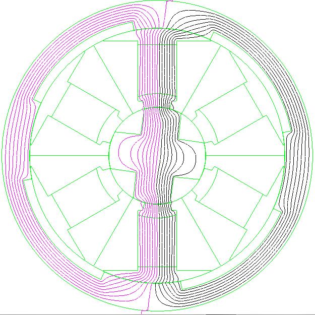
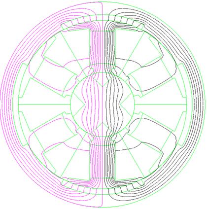


13 Progress In Electromagnetics Research, Vol. 140, Figure 9. Flux flow at various rotor position.
14 536 Vaithilingam et al. full overlap positions. Similar to the case of non-overlap position, the useful torque generation is null. However, a smaller angle displacement influences the flux flow, and thereby the torque value starts to buildup. With the unsymmetrical design values extended inductance profile (which is a function of the flux linkage for the injected current) is derived. The extended inductance slope increases the co-energy surface area (W co ) over the same rotor pole pitch thereby increases the torque to a higher value. Figure 10 shows the co-energy area derived for the DRRM. The co-energy value is derived from the integration of the area shown in the bounded region. As the torque generated is proportional to the energy variation of operation this characteristic provides knowledge on the machine characteristics. The co-energy value for the DRRM is computed using Equation (24). T e = δw co δθ = 1 2 [ La L u θ a θ u ] i 2 (24) Figure 11 shows the inductance characteristics of the DRRM with different current value. As can be seen, inductance varies as the current injected is increased. However, the increase of current is accompanied by the heating loss in the coil. Since the machine is sequentially excited and not continuously excited, the heat loss is considerably smaller than its counter-part machines [1]. The functionality operation of such a type of machine with the driver circuit is available in [20]. The cutway representation of the fabricated DRRM is as shown in Figure 12. Figure 10. Flux linkage characteristics. Figure 11. Inductance characteristics with different current excitation.
 is lower. The maximum torque achieved is about 1.7549 N.")
15 Progress In Electromagnetics Research, Vol. 140, Inner Rotor Figure 12. DRRM cutway view. Figure 13. Static torque characteristics Static Torque Characteristics Figure 13 shows the static numerical characteristics of the DRRM. As can be seen, the torque characteristics is closer to sinusoidal, and hence the Total Harmonic Distortion (THD) is lower. The maximum torque achieved is about N.m with the average torque value of N- m with a THD of 13.4% through the FEA analysis. Figure 14 shows the torque characteristics with various mmf values. It is imperative that with higher mmf value the torque generated is higher, but it comes with the compromise on the increase of size to accommodate for the increase in the number of turns or bigger conductor size. This increases the copper losses inside the machine. The mmf for the designed machine is kept at AT. Figure 15 shows the three-phase sequential excitation of the DRRM through FEA. The torque ripple between the phases is found to be about 10.55%. 5. COMPARISON OF CRM AND DRRM 5.1. Parametric Design To perform a comparative evaluations of the DRRM and the conventional CRM structure, both are built to the same size, volume and similar operating conditions through the FEA tool. Figure 16 shows the concept machine dimensions of the conventional CRM and DRRM. The choice of pole-arc for the CRM is based on [2] and the choice of the DRRM based on the selected value in this design. Both machines are of 6/4 configuration and three phase machine with uniform bore and stack values. Both the machines are constructed and
16 538 Vaithilingam et al. Figure 14. Torque characteristics with different current excitations. Figure 15. FEA three phase torque characteristics. Figure 16. CRM and DRRM configurations. designed using the same FEA tool for performance evaluations. Table 4 shows the mechanical dimensions of the CRM and DRRM. Both the machines are designed with the same bore length, stack length, and overall mass. As can be seen from the values, the net volume is the same for both the CRM and DRRM; however, the rotor area surface is significantly higher for DRRM as it encloses two rotors Evaluations Parameters Total Harmonic Distortion The symmetrical nature of torque profile inside the machine derives reduced or zero ripples in the machine. A quantifiable measure, the total harmonic distortion (THD), which is a measure of the distortion in the signal due to oscillations at the harmonics of the input signal, is
17 Progress In Electromagnetics Research, Vol. 140, Table 4. Parameter values of CRM and DRRM. Parameter CRM DRRM Number of Stator Poles 6 6 Number of Rotor Poles 4 4 Outer Radius of Stator 40 mm 40 mm Inner Radius of Stator 19 mm 35 mm Outer Radius of Rotor 18.9 mm mm Inner radius of rotor 8 mm 13 mm Stack Length 40 mm 40 mm Stator Pole-arc (β s ) 35 Stator Inner Teeth Pole-arc (β is ) 30 Stator Outer Teeth Pole-arc (β os ) 50 Rotor Pole-arc (β r ) 30 Outer Rotor Pole-arc (β or ) 45 Inner Rotor Pole-arc (β ir ) 35 Number of Phases 3 3 Air gap Length (lg) 0.1 mm Outer Air-gap Length (lg1) 0.05 mm Inner Air-gap Length (lg2) 0.05 mm mmf AT AT Stator Area mm mm 2 Stator Mass gms gms Rotor Volume mm mm 3 Rotor Area mm mm 2 Rotor Mass gms gms Net Volume mm mm 3 used as a factor to evaluate the ripple and is defined as in Equation (25). THD = i=2 (F i) 2 F 1 (25) Motor Constant Square Density The motor constant square density (G) is a motor performance parameter of the motor to transform electrical power to mechanical
18 540 Vaithilingam et al. power and is a valuable tool for the application engineer particularly for recommending a best fit replacement for a competitors motor [6]. This constant is chosen since it relates to the torque, power and volume of the motor. The motor constant square density is given as in Equation (26). G = (k m) 2 (26) V where V is the volume of the motor and the motor constant k m is given as in Equation (27). k m = k t Pin (27) and the torque constant k T is stated as in Equation (28). k t = T f I (28) 5.3. Comparative Evaluations Magnetic and Mechanical Characteristics Figure 17 shows the static torque characteristics of the CRM and the DRRM. Figure 18 shows the motoring slope characteristics of both the CRM and DRRM. As can be seen, compared to the DRRM, although the slope value of the CRM is higher, the motoring characteristic reaches the constant value at about 15. In other words, it reaches the dead-zone where the slope is constant, hence the torque generating capability is reduced. However, the slope value for the DRRM is Figure 17. Comparison of the torque characteristics. Figure 18. Comparison of the motoring slope characteristics.
19 Progress In Electromagnetics Research, Vol. 140, linear and extend till 20 which shows the extended torque generating capability. Hence the torque value is better than that of the CRM. Figure 19 shows the torque characteristics with different mmf values. As the torque generation is a function of impressed current, it is worth of this analysis. In the conventional machine for lower mmf value, the torque characteristics are relatively uneven, whereas for the proposed DRRM the torque pattern at various mmf values is almost symmetrical. Figure 19. Comparison of torque characteristics with different mmf values Loss Characteristics The core-loss is computed based on Figure 20. With the flux density value, the iron loss of the system is computed. The total loss of the machine at any one rotor position is computed by multiplying the weighing factor and operating frequency. The loss characteristics computed through analytical and simulation for both the motors aew as shown in Figure Quality Factor Figure 22 shows the THD comparisons of the two models. It is inferred that the DRRM increases average torque by 23% with the THD reduced by 79% compared to that of CRM. An improved sinusoidal symmetric waveform is expected to have reduced THD as evident from the analysis. The maximum torque generated by the DRRM is about Nm with the THD value of 13.4%. The maximum torque generated by the CRM is about N-m with THD value of 67.1%. Table 5 shows the comparison of the CRM with DRRM in terms of quality factors.
20 542 Vaithilingam et al. Figure 20. Core-loss computation method. Figure 21. Loss characteristics. Figure 22. Comparison of harmonic components. Table 5. Comparison evaluations using quality factor. Machine THD K t K m G [%] [Nm] [Nm/A/W] [Nm/A/W/mm 3 ] CRM DRRM CONCLUSIONS The fundamental concepts in deriving the dual-air-gap structure is realised through the proposed novel structure, Double Rotor Reluctance Motor (DRRM). The numerical FEA tool is used for the analysis of such a structure to derive the electro-magnetic
21 Progress In Electromagnetics Research, Vol. 140, characteristics. A comparative evaluation of the double rotor reluctance machine with that of the conventional reluctance machine is performed. The maximum torque generated by the selected dual-airgap structure is Nm and for conventional structure is Nm. Also, the dual-air-gap structure exhibits 65% increase in average torque value compared with that of the conventional single-air-gap structure. REFERENCES 1. Miller, T. J. E., Switched Reluctance Motors and Their Control, Magna Physics and Clarendon Press, Oxford, Krishnan, R., Design Procedure for Switched-reluctance Motors Design, Wiley-Interscience, New York, Aravind, C. V., M. Norhisam, I. Aris, M. H. Marhabhan, D. Ahmad, and M. Nirei, Double rotor switched reluctance motors: Fundamentals and magnetic circuit analysis, IEEE Student Conference on Research and Development (SCORED2011), , Cyberjaya, Malaysia, Dec , Norhisam, M., K. C. Wong, N. Mariun, and H. Wakiwaka, Double side interior permanent magnet linear synchronous motor and drive system, International Conference on Power Electronics and Drives Systems, PEDS, Vol. 2, , Nov , Norhisam, M., S. Ridzuan, R. N. Firdaus, C. V. Aravind, H. Wakiwaka, and M. Nirei, Comparative evaluation on powerspeed density of portable permanent magnet generators for agricultural application, Progress In Electromagnetic Research, Vol. 129, , Norhisam, M, M. Norafiza, and C. Y. Sia, Double stator type permanent magnet generator, 2009 IEEE Student Conference on Research and Development (SCOReD), , Nov , Zhang, D., S. X. Niu, K. T. Chau, J. Z. Jiang, and Y. Gong, Design and analysis of a double-stator cup-rotor directly driven permanent magnet wind power generator, CES/IEEE 5th International Power Electronics and Motion Control Conference, Vol. 3, 1 5, Aug , Peng, W., F. G. Zhang, and J.-W. Ahn, Design and control of a novel bearingless SRM with double stator, 2012 IEEE International Symposium on Industrial Electronics (ISIE), , May 28 31, Li, L. B., Q. Y. Zhao, G. K. Shi, and H. J. Wang, Analysis of feasibility of double-rotor motor applied to hybrid electric
22 544 Vaithilingam et al. vehicle, Vehicle Power and Propulsion Conference, 1 5, Sep. 3 5, Hoeijmakers, M. J. and J. A. Ferreira, The electric variable transmission, IEEE Transactions on Industry Applications, Vol. 42, No. 4, , Jul. Aug Liu, C. and K. T. Chau Electromagnetic design and analysis of double rotor flux modulated permanent magnet machines, Progress In Electromagnetics Research, Vol. 131, 81 97, Torkaman, H. and E. Afjei, Radial force characteristic assessment in a novel two-phase dual layer SRG using FEM, Progress In Electromagnetics Research, Vol. 125, , Cui, S. M., Y. J. Yuan, and T. C. Wang, Research on switched reluctance double-rotor motor used for hybrid electric vehicle, International Conference on Electrical Machines and Systems, ICEMS, , Oct , Norhisam, M., C. V. Aravind, H. Marhaban, I. Aris, and M. Nirei, Multi-rotor reluctance motor, Malaysian Intellectual Property Filing Agency, Malaysia, Mar Torkaman, H. and E. Afjei, Comparison of three novel types of two-phase switched reluctance motors using finite element method, Progress In Electromagnetics Research, Vol. 125, , Torkaman, H. and E. Afjei, FEM analysis of angular misalignment fault in SRM magnetostatic characteristics, Progress In Electromagnetics Research, Vol. 104, 31 48, Mahmoudi, A., N. A. Rahim, and H. W. Ping, Axial-flux permanent-magnet motor design for electric vehicle direct drive using sizing equation and finite element analysis, Progress In Electromagnetics Research, Vol. 122, , Kameari, A., Local force calculation in 3D FEM with edge elements, International Journal of Applied Electromagnetics in Materials, Vol. 3, , Aravind C. V., M. Norhisam, M. H. Marhaban, and I. Aris, Analytical design of double rotor switched reluctance motor using optimal pole arc values, International Review in Electrical and Electronics, Vol. 7, No. 1, , Feb
Inductance profile estimation of high-speed Switched Reluctance Machine with rotor eccentricity
 Inductance profile estimation of high-speed Switched Reluctance Machine with rotor eccentricity Rajdeep Banerjee, Parthasarathi Sensarma Department of Electrical Engineering IIT Kanpur, India Email: brajdeep@iitk.ac.in,
Analytical Calculation of Air Gap Magnetic Field Distribution in Vernier Motor
 IEEE PEDS 017, Honolulu, USA 1-15 June 015 Analytical Calculation of Air Gap Magnetic Field Distribution in Vernier Motor Hyoseok Shi, Noboru Niguchi, and Katsuhiro Hirata Department of Adaptive Machine
Keywords: Electric Machines, Rotating Machinery, Stator faults, Fault tolerant control, Field Weakening, Anisotropy, Dual rotor, 3D modeling
 Analysis of Electromagnetic Behavior of Permanent Magnetized Electrical Machines in Fault Modes M. U. Hassan 1, R. Nilssen 1, A. Røkke 2 1. Department of Electrical Power Engineering, Norwegian University
PRINCIPLE OF DESIGN OF FOUR PHASE LOW POWER SWITCHED RELUCTANCE MACHINE AIMED TO THE MAXIMUM TORQUE PRODUCTION
 Journal of ELECTRICAL ENGINEERING, VOL. 55, NO. 5-6, 24, 138 143 PRINCIPLE OF DESIGN OF FOUR PHASE LOW POWER SWITCHED RELUCTANCE MACHINE AIMED TO THE MAXIMUM TORQUE PRODUCTION Martin Lipták This paper
4 Finite Element Analysis of a three-phase PM synchronous machine
 Assignment 4 1-1 4 Finite Element Analysis of a three-phase PM synchronous machine The goal of the third assignment is to extend your understanding on electromagnetic analysis in FEM. This assignment is
Equal Pitch and Unequal Pitch:
 Equal Pitch and Unequal Pitch: Equal-Pitch Multiple-Stack Stepper: For each rotor stack, there is a toothed stator segment around it, whose pitch angle is identical to that of the rotor (θs = θr). A stator
Guangjin Li, Javier Ojeda, Emmanuel Hoang, Mohamed Gabsi, Cederic Balpe. To cite this version:
 Design of Double Salient Interior Permanent Magnet Machine Based on Mutually Coupled Reluctance Machine for Increasing the Torque Density and Flux-Weakening Capability Guangjin Li, Javier Ojeda, Emmanuel
Design and Analysis of Permanent Magnet Motor with Movable Stators
 Progress In Electromagnetics Research B, Vol. 58, 219 232, 2014 Design and Analysis of Permanent Magnet Motor with Movable Stators Chun-Chi Lai 1, Tzong-Shi Liu 1, *, and Ming-Tsan Peng 2 Abstract Permanent-magnet
Doubly salient reluctance machine or, as it is also called, switched reluctance machine. [Pyrhönen et al 2008]
![Doubly salient reluctance machine or, as it is also called, switched reluctance machine. [Pyrhönen et al 2008]](/thumbs/86/93665357.jpg "Doubly salient reluctance machine or, as it is also called, switched reluctance machine. [Pyrhönen et al 2008]") Doubly salient reluctance machine or, as it is also called, switched reluctance machine [Pyrhönen et al 2008] Pros and contras of a switched reluctance machine Advantages Simple robust rotor with a small
Doubly salient reluctance machine or, as it is also called, switched reluctance machine [Pyrhönen et al 2008] Pros and contras of a switched reluctance machine Advantages Simple robust rotor with a small
Unified Torque Expressions of AC Machines. Qian Wu
 Unified Torque Expressions of AC Machines Qian Wu Outline 1. Review of torque calculation methods. 2. Interaction between two magnetic fields. 3. Unified torque expression for AC machines. Permanent Magnet
Measurement of Flux Linkage and Inductance Profile of SRM
 Measurement of Flux Linkage and Inductance Profile of SRM Rakesh Saxena, Bhim Singh and Yogesh Pahariya Abstract The main goal in modeling of SRM is to provide a good accuracy over the entire speed and
Analytical Model for Sizing the Magnets of Permanent Magnet Synchronous Machines
 Journal of Electrical Engineering 3 (2015) 134-141 doi: 10.17265/2328-2223/2015.03.004 D DAVID PUBLISHING Analytical Model for Sizing Magnets of Permanent Magnet Synchronous Machines George Todorov and
IEEE Transactions on Applied Superconductivity. Copyright IEEE.
 Title Loss analysis of permanent magnet hybrid brushless machines with and without HTS field windings Author(s) Liu, C; Chau, KT; Li, W Citation The 21st International Conference on Magnet Technology,
Hybrid Excited Vernier Machines with All Excitation Sources on the Stator for Electric Vehicles
 Progress In Electromagnetics Research M, Vol. 6, 113 123, 16 Hybrid Excited Vernier Machines with All Excitation Sources on the Stator for Electric Vehicles Liang Xu, Guohai Liu, Wenxiang Zhao *, and Jinghua
THEORETICAL AND EXPERIMENTAL STUDY OF A MODULAR TUBULAR TRANSVERSE FLUX RELUC- TANCE MACHINE
 Progress In Electromagnetics Research, Vol. 139, 41 55, 2013 THEORETICAL AND EXPERIMENTAL STUDY OF A MODULAR TUBULAR TRANSVERSE FLUX RELUC- TANCE MACHINE Dan-Cristian Popa *, Vasile-Ioan Gliga, and Loránd
Loss Minimization Design Using Magnetic Equivalent Circuit for a Permanent Magnet Synchronous Motor
 Loss Minimization Design Using Magnetic Equivalent Circuit for a Permanent Magnet Synchronous Motor Daisuke Sato Department of Electrical Engineering Nagaoka University of Technology Nagaoka, Niigata,
Accurate Joule Loss Estimation for Rotating Machines: An Engineering Approach
 Accurate Joule Loss Estimation for Rotating Machines: An Engineering Approach Adeeb Ahmed Department of Electrical and Computer Engineering North Carolina State University Raleigh, NC, USA aahmed4@ncsu.edu
THE INFLUENCE OF THE ROTOR POLE SHAPE ON THE STATIC EFICIENCY OF THE SWITCHED RELUCTANCE MOTOR
 7 th INTERNATIONAL MULTIDISCIPLINARY CONFERENCE Baia Mare, Romania, May 17-18, 27 ISSN-1224-3264 THE INFLUENCE OF THE ROTOR POLE SHAPE ON THE STATIC EFICIENCY OF THE SWITCHED RELUCTANCE MOTOR Liviu Neamţ,
AXIAL FLUX INTERIOR PERMANENT MAGNET SYNCHRONOUS MOTOR WITH SINUSOIDALLY SHAPED MAGNETS
 AXIAL FLUX INTERIOR PERMANENT MAGNET SYNCHRONOUS MOTOR WITH SINUSOIDALLY SHAPED MAGNETS A. Parviainen, J. Pyrhönen, M. Niemelä Lappeenranta University of Technology, Department of Electrical Engineering
ANALYTICAL COMPUTATION OF RELUCTANCE SYN- CHRONOUS MACHINE INDUCTANCES UNDER DIF- FERENT ECCENTRICITY FAULTS
 Progress In Electromagnetics Research M, Vol. 24, 29 44, 2012 ANALYTICAL COMPUTATION OF RELUCTANCE SYN- CHRONOUS MACHINE INDUCTANCES UNDER DIF- FERENT ECCENTRICITY FAULTS H. Akbari * Department of Electrical
White Rose Research Online URL for this paper:
 This is a repository copy of Eddy-current loss in the rotor magnets of permanent-magnet brushless machines having a fractional number of slots per pole. White Rose Research Online URL for this paper: http://eprints.whiterose.ac.uk/861/
Analysis of Anti-Notch Method to the Reduction of the Cogging Torque in Permanent Magnet Synchronous Generator
 International Journal of Scientific & Engineering Research, Volume 7, Issue 12, December-2016 1301 Analysis of Anti-Notch Method to the Reduction of the Cogging Torque in Permanent Magnet Synchronous Generator
1439. Numerical simulation of the magnetic field and electromagnetic vibration analysis of the AC permanent-magnet synchronous motor
 1439. Numerical simulation of the magnetic field and electromagnetic vibration analysis of the AC permanent-magnet synchronous motor Bai-zhou Li 1, Yu Wang 2, Qi-chang Zhang 3 1, 2, 3 School of Mechanical
Parameter Prediction and Modelling Methods for Traction Motor of Hybrid Electric Vehicle
 Page 359 World Electric Vehicle Journal Vol. 3 - ISSN 232-6653 - 29 AVERE Parameter Prediction and Modelling Methods for Traction Motor of Hybrid Electric Vehicle Tao Sun, Soon-O Kwon, Geun-Ho Lee, Jung-Pyo
2577. The analytical solution of 2D electromagnetic wave equation for eddy currents in the cylindrical solid rotor structures
 2577. The analytical solution of 2D electromagnetic wave equation for eddy currents in the cylindrical solid rotor structures Lale T. Ergene 1, Yasemin D. Ertuğrul 2 Istanbul Technical University, Istanbul,
Torque Constant Density in Different Type of Double Stator Permanent Magnet Brushless DC Motor
 Progress In Electromagnetics Research M, Vol. 66, 127 142, 2018 Torque Constant Density in Different Type of Double Stator Permanent Magnet Brushless DC Motor Raja Nor Firdaus Kashfi Raja Othman 1, 2,
Modeling and Design Optimization of Permanent Magnet Linear Synchronous Motor with Halbach Array
 Modeling and Design Optimization of Permanent Magnet Linear Synchronous Motor with Halbach Array N. Roshandel Tavana, and A. Shoulaie nroshandel@ee.iust.ir, and shoulaie@ee.iust.ac.ir Department of Electrical
Cogging torque reduction of Interior Permanent Magnet Synchronous Motor (IPMSM)
") Scientia Iranica D (2018) 25(3), 1471{1477 Sharif University of Technology Scientia Iranica Transactions D: Computer Science & Engineering and Electrical Engineering http://scientiairanica.sharif.edu Cogging
Scientia Iranica D (2018) 25(3), 1471{1477 Sharif University of Technology Scientia Iranica Transactions D: Computer Science & Engineering and Electrical Engineering http://scientiairanica.sharif.edu Cogging
MODELING surface-mounted permanent-magnet (PM)
") Modeling of Axial Flux Permanent-Magnet Machines Asko Parviainen, Markku Niemelä, and Juha Pyrhönen Abstract In modeling axial field machines, three dimensional (3-D) finite-element method (FEM) models
Modeling of Axial Flux Permanent-Magnet Machines Asko Parviainen, Markku Niemelä, and Juha Pyrhönen Abstract In modeling axial field machines, three dimensional (3-D) finite-element method (FEM) models
Finite Element Analysis of Hybrid Excitation Axial Flux Machine for Electric Cars
 223 Finite Element Analysis of Hybrid Excitation Axial Flux Machine for Electric Cars Pelizari, A. ademir.pelizari@usp.br- University of Sao Paulo Chabu, I.E. ichabu@pea.usp.br - University of Sao Paulo
Static Analysis of 18-Slot/16-Pole Permanent Magnet Synchronous Motor Using FEA
 International Journal of Engineering and Technology Volume 5 No. 3,March, 2015 Static Analysis of 18-Slot/16-Pole Permanent Magnet Synchronous Motor Using FEA M. Rezal 1, Dahaman Ishak 2, M. Sabri 1, Al-Hapis
Static Characteristics of Switched Reluctance Motor 6/4 By Finite Element Analysis
 Australian Journal of Basic and Applied Sciences, 5(9): 1403-1411, 2011 ISSN 1991-8178 Static Characteristics of Switched Reluctance Motor 6/4 By Finite Element Analysis 1 T. Jahan. 2 M.B.B. Sharifian
Analytical Method for Predicting the Air-Gap Flux Density of Dual-Rotor Permanent- Magnet (DRPM) Machine
 Machine") Analytical Method for Predicting the Air-Gap Flux Density of Dual-Rotor Permanent- Magnet (DRPM) Machine W.Xie, G.Dajaku*, D.Gerling Institute for Electrical Drives and Actuators, University of Federal
Analytical Method for Predicting the Air-Gap Flux Density of Dual-Rotor Permanent- Magnet (DRPM) Machine W.Xie, G.Dajaku*, D.Gerling Institute for Electrical Drives and Actuators, University of Federal
Proceedings of the 6th WSEAS/IASME Int. Conf. on Electric Power Systems, High Voltages, Electric Machines, Tenerife, Spain, December 16-18,
 Proceedings of the 6th WSEAS/IASME Int. Conf. on Electric Power Systems, High Voltages, Electric Machines, Tenerife, Spain, December 16-18, 2006 196 A Method for the Modeling and Analysis of Permanent
Comprehensive Analysis and Evaluation of Cogging Torque in Axial Flux Permanent Magnet Machines
 Comprehensive Analysis and Evaluation of Cogging Torque in Axial Flux Permanent Magnet Machines A. P. Ferreira, Member, IEEE, A. V. Leite, Member, IEEE and A. F. Costa Abstract Evaluation and minimization
Performance analysis of variable speed multiphase induction motor with pole phase modulation
 ARCHIVES OF ELECTRICAL ENGINEERING VOL. 65(3), pp. 425-436 (2016) DOI 10.1515/aee-2016-0031 Performance analysis of variable speed multiphase induction motor with pole phase modulation HUIJUAN LIU, JUN
Vehicular Suspension and Propulsion Using Double Sided Linear Induction Machines
 Vehicular Suspension and Propulsion Using Double Sided Linear Induction Machines Tom Cox Power Electronics Machines and Control Group The University of Nottingham Nottingham, UK t.cox@nottingham.ac.uk
ROEVER COLLEGE OF ENGINEERING & TECHNOLOGY ELAMBALUR, PERAMBALUR DEPARTMENT OF ELECTRICAL AND ELECTRONICS ENGINEERING ELECTRICAL MACHINES I
 ROEVER COLLEGE OF ENGINEERING & TECHNOLOGY ELAMBALUR, PERAMBALUR-621220 DEPARTMENT OF ELECTRICAL AND ELECTRONICS ENGINEERING ELECTRICAL MACHINES I Unit I Introduction 1. What are the three basic types
CHAPTER 3 INFLUENCE OF STATOR SLOT-SHAPE ON THE ENERGY CONSERVATION ASSOCIATED WITH THE SUBMERSIBLE INDUCTION MOTORS
 38 CHAPTER 3 INFLUENCE OF STATOR SLOT-SHAPE ON THE ENERGY CONSERVATION ASSOCIATED WITH THE SUBMERSIBLE INDUCTION MOTORS 3.1 INTRODUCTION The electric submersible-pump unit consists of a pump, powered by
Regular paper. Design and FE Analysis of BLDC Motor for Electro- Mechanical Actuator
 P.Srinivas* J. Electrical Systems 11-1 (2015): 76-88 Regular paper Design and FE Analysis of BLDC Motor for Electro- Mechanical Actuator JES Journal of Electrical Systems This paper presents the design
Magnetic vibration analysis of a new DC-excited multitoothed switched reluctance machine. Liu, C; Chau, KT; Lee, CHT; Lin, F; Li, F; Ching, TW
 Title Magnetic vibration analysis of a new DC-excited multitoothed switched reluctance machine Author(s) Liu, C; Chau, KT; Lee, CHT; Lin, F; Li, F; Ching, TW Citation The 2014 IEEE International Magnetics
General Characteristic of Fractional Slot Double Layer Concentrated Winding Synchronous Machine
 J Electr Eng Technol Vol. 8, No. 2: 282-287, 2013 http://dx.doi.org/10.5370/jeet.2013.8.2.282 ISSN(Print) 1975-0102 ISSN(Online) 2093-7423 General Characteristic of Fractional Slot Double Layer Concentrated
Torque Ripple Reduction Using Torque Compensation Effect of an Asymmetric Rotor Design in IPM Motor
 Journal of Magnetics 22(2), 266-274 (2017) ISSN (Print) 1226-1750 ISSN (Online) 2233-6656 https://doi.org/10.4283/jmag.2017.22.2.266 Torque Ripple Reduction Using Torque Compensation Effect of an Asymmetric
Torque Analysis of Permanent Magnet Hybrid Stepper Motor using Finite Element Method for Different Design Topologies
 International Journal of Power Electronics and Drive System (IJPEDS) Vol.2, No.1, March 212, pp. 17~116 ISSN: 288-8694 17 Torque Analysis of Permanent Magnet Hybrid Stepper Motor using Finite Element Method
Effects of Different Rotor and Stator Constructions on The Performance of Switched Reluctance Motors
 Proceedings of the 6th WSEAS International Conference on Applications of Electrical Engineering, Istanbul, Turkey, May 27-29, 27 183 Effects of Different Rotor and Stator Constructions on The Performance
Electromagnetic field analysis of novel low cogging force, linear switched reluctance motor, based on 2-D finite element method
 Energy Equip. Sys./ Vol. 5/No.3/September 2017/ 227-240 Energy Equipment and Systems http://energyequipsys.ut.ac.ir www.energyequipsys.com Electromagnetic field analysis of novel low cogging force, linear
The initial magnetization curve shows the magnetic flux density that would result when an increasing magnetic field is applied to an initially
 MAGNETIC CIRCUITS The study of magnetic circuits is important in the study of energy systems since the operation of key components such as transformers and rotating machines (DC machines, induction machines,
1. Introduction. (Received 21 December 2012; accepted 28 February 2013)
") 940. Magnetic equivalent circuit model of surface type fractional-slot permanent magnet synchronous generator Y. Oner, I. enol,. Bekiroglu, E. Aycicek Y. Oner 1, I. enol 2,. Bekiroglu 3, E. Aycicek 4 Yıldız
940. Magnetic equivalent circuit model of surface type fractional-slot permanent magnet synchronous generator Y. Oner, I. enol,. Bekiroglu, E. Aycicek Y. Oner 1, I. enol 2,. Bekiroglu 3, E. Aycicek 4 Yıldız
A Novel Pseudo-Direct-Drive Permanent-Magnet Machine with Less Magnet
 Machine Copy for Proofreading, Vol. x, y z, 2016 A Novel Pseudo-Direct-Drive Permanent-Magnet Machine with Less Magnet Xin Yin, Pierre-Daniel Pfister * and Youtong Fang Abstract Magnetic gears (MGs), an
Revision Guide for Chapter 15
 Revision Guide for Chapter 15 Contents Revision Checklist Revision otes Transformer...4 Electromagnetic induction...4 Lenz's law...5 Generator...6 Electric motor...7 Magnetic field...9 Magnetic flux...
SCIENCE CHINA Technological Sciences. Nonlinear magnetic network models for flux-switching permanent magnet machines
 SCIENCE CHINA Technological Sciences Article March 2016 Vol.59 No.3: 494 505 doi: 10.1007/s11431-015-5968-z Nonlinear magnetic network models for flux-switching permanent magnet machines ZHANG Gan, HUA
Experimental Assessment of Unbalanced Magnetic Force according to Rotor Eccentricity in Permanent Magnet Machine
 Journal of Magnetics 23(1), 68-73 (218) ISSN (Print) 1226-175 ISSN (Online) 2233-6656 https://doi.org/1.4283/jmag.218.23.1.68 Experimental Assessment of Unbalanced Magnetic Force according to Rotor Eccentricity
Third harmonic current injection into highly saturated multi-phase machines
 ARCHIVES OF ELECTRICAL ENGINEERING VOL. 66(1), pp. 179-187 (017) DOI 10.1515/aee-017-001 Third harmonic current injection into highly saturated multi-phase machines FELIX KLUTE, TORBEN JONSKY Ostermeyerstraße
Dynamic Modeling of Surface Mounted Permanent Synchronous Motor for Servo motor application
 797 Dynamic Modeling of Surface Mounted Permanent Synchronous Motor for Servo motor application Ritu Tak 1, Sudhir Y Kumar 2, B.S.Rajpurohit 3 1,2 Electrical Engineering, Mody University of Science & Technology,
UJET VOL. 2, NO. 2, DEC Page 8
 UMUDIKE JOURNAL OF ENGINEERING AND TECHNOLOGY (UJET) VOL. 2, NO. 2, DEC 2016 PAGE 8-15 FINITE ELEMENT ANALYSIS OF A 7.5KW ASYNCHRONOUS MOTOR UNDER INTERMITTENT LOADING. Abunike, E. C. and Okoro, O. I.
Revision Guide for Chapter 15
 Revision Guide for Chapter 15 Contents tudent s Checklist Revision otes Transformer... 4 Electromagnetic induction... 4 Generator... 5 Electric motor... 6 Magnetic field... 8 Magnetic flux... 9 Force on
Analytical and numerical computation of the no-load magnetic field in induction motors
 Analytical and numerical computation of the no-load induction motors Dan M. Ionel University of Glasgow, Glasgow, Scotland, UK and Mihai V. Cistelecan Research Institute for Electrical Machines, Bucharest
Inductance Testing According to the New IEEE Std 1812 Application and Possible Extensions for IPM Machines
 Inductance Testing According to the New IEEE Std 1812 Application and Possible Extensions for IPM Machines Vandana Rallabandi Narges Taran Dan M. Ionel Department of Electrical and Computer Engineering
Cogging Torque Reduction in Permanent-Magnet Brushless Generators for Small Wind Turbines
 Journal of Magnetics 20(2), 176-185 (2015) ISSN (Print) 1226-1750 ISSN (Online) 2233-6656 http://dx.doi.org/10.4283/jmag.2015.20.2.176 Cogging Torque Reduction in Permanent-Magnet Brushless Generators
Citation Ieee Transactions On Magnetics, 2001, v. 37 n. 4 II, p
 Title Design and analysis of a new doubly salient permanent magnet motor Author(s) Cheng, M; Chau, KT; Chan, CC Citation Ieee Transactions On Magnetics, 2001, v. 37 n. 4 II, p. 3012-3020 Issued Date 2001
STAR-CCM+ and SPEED for electric machine cooling analysis
 STAR-CCM+ and SPEED for electric machine cooling analysis Dr. Markus Anders, Dr. Stefan Holst, CD-adapco Abstract: This paper shows how two well established software programs can be used to determine the
Research of double claw-pole structure generator
 Available online www.jocpr.com Journal of Chemical and Pharmaceutical Research, 2014, 6(6):1184-1190 Research Article ISSN : 0975-7384 CODEN(USA) : JCPRC5 Research of double claw-pole structure generator
Analytical Model for Permanent Magnet Motors With Surface Mounted Magnets
 386 IEEE TRANSACTIONS ON ENERGY CONVERSION, VOL. 18, NO. 3, SEPTEMBER 2003 Analytical Model for Permanent Magnet Motors With Surface Mounted Magnets Amuliu Bogdan Proca, Member, IEEE, Ali Keyhani, Fellow,
Analytical Method for Magnetic Field Calculation in a Low-Speed Permanent-Magnet Harmonic Machine
 Vol. 5 No.5/ May. 2011 Analytical Method for Magnetic Field Calculation in a Low-Speed Permanent-Magnet Harmonic Machine ABSTRACT Magnetic-gearing effect has become increasingly attractive when designing
Optimum design of a double-sided permanent magnet linear synchronous motor to minimize the detent force
 Energy Equip. Sys./ Vol. 5/No1/March 2017/ 1-11 Energy Equipment and Systems http://energyequipsys.ut.ac.ir www.energyequipsys.com Optimum design of a double-sided permanent magnet linear synchronous motor
Development of a Double-Sided Consequent Pole Linear Vernier Hybrid Permanent-Magnet Machine for Wave Energy Converters
 Development of a Double-Sided Consequent Pole Linear Vernier Hybrid Permanent-Magnet Machine for Wave Energy Converters A. A. Almoraya, N. J. Baker, K. J. Smith and M. A. H. Raihan Electrical Power Research
A Novel Linear Switched Reluctance Machine: Analysis and Experimental Verification
 American J. of Engineering and Applied Sciences 3 (2): 433-440, 2010 ISSN 1941-7020 2010 Science Publications A Novel Linear Switched Reluctance Machine: Analysis and Experimental Verification 1 N.C. Lenin
PCIM Europe 2011, May 2011, Nuremberg, Germany Paper 160
 A Rotary-Linear Switched Reluctance Motor for Advanced Industrial Applications Ioana BEŢIA, Technical University of Cluj-apoca, Romania, Ioana.Bentia@mae.utcluj.ro Mircea RUBA, Technical University of
A Simple Nonlinear Model of the Switched Reluctance Motor
 IEEE TRANSACTIONS ON ENERGY CONVERSION, VOL 15, NO 4, DECEMBER 2000 395 A Simple Nonlinear Model of the Switched Reluctance Motor Vladan Vujičić and Slobodan N Vukosavić Abstract The paper presents a simple
Research on Permanent Magnet Linear Synchronous Motor Control System Simulation *
 Available online at www.sciencedirect.com AASRI Procedia 3 (2012 ) 262 269 2012 AASRI Conference on Modeling, Identification and Control Research on Permanent Magnet Linear Synchronous Motor Control System
UNIT-I INTRODUCTION. 1. State the principle of electromechanical energy conversion.
 UNIT-I INTRODUCTION 1. State the principle of electromechanical energy conversion. The mechanical energy is converted in to electrical energy which takes place through either by magnetic field or electric
Eddy Current Heating in Large Salient Pole Generators
 Eddy Current Heating in Large Salient Pole Generators C.P.Riley and A.M. Michaelides Vector Fields Ltd., 24 Bankside, Kidlington, Oxford OX5 1JE, UK phone: (+44) 1865 370151, fax: (+44) 1865 370277 e-mail:
Analytical Solution of Magnetic Field in Permanent-Magnet Eddy-Current Couplings by Considering the Effects of Slots and Iron-Core Protrusions
 Journal of Magnetics 20(3), 273-283 (2015) ISSN (Print) 1226-1750 ISSN (Online) 2233-6656 http://dx.doi.org/10.4283/jmag.2015.20.3.273 Analytical Solution of Magnetic Field in Permanent-Magnet Eddy-Current
Step Motor Modeling. Step Motor Modeling K. Craig 1
 Step Motor Modeling Step Motor Modeling K. Craig 1 Stepper Motor Models Under steady operation at low speeds, we usually do not need to differentiate between VR motors and PM motors (a hybrid motor is
THE THEORETICAL AND EXPERIMENTAL STUDY OF CLAW POLE ALTERNATORS
 FACULTY OF ELECTRICAL ENGINEERING Cristian Petru BARZ THE THEORETICAL AND EXPERIMENTAL STUDY OF CLAW POLE ALTERNATORS -PHD THESIS- (abstract) Scientific advisor, Prof.dr. Vasile IANCU 2010 The INTRODUCTION
Optimisation of Inner Diameter to Outer Diameter Ratio of Axial Flux Permanent Magnet Generator
 IOSR Journal of Electrical and Electronics Engineering (IOSR-JEEE) e-issn: 2278-1676,p-ISSN: 220-1, Volume 9, Issue 6 Ver. III (Nov Dec. 2014), PP 4-47 Optimisation of Inner Diameter to Outer Diameter
Generators for wind power conversion
 Generators for wind power conversion B. G. Fernandes Department of Electrical Engineering Indian Institute of Technology, Bombay Email : bgf@ee.iitb.ac.in Outline of The Talk Introduction Constant speed
The Nottingham eprints service makes this work by researchers of the University of Nottingham available open access under the following conditions.
 Arumugam, Puvaneswaran and Dusek, Jiri and Mezani, Smail and Hamiti, Tahar and Gerada, C. (2015) Modeling and analysis of eddy current losses in permanent magnet machines with multi-stranded bundle conductors.
Cogging Torque Reduction in Surface-mounted Permanent Magnet Synchronous Motor by Axial Pole Pairing
 EVS28 KINTEX, Korea, May 3-6, 215 Cogging Torque Reduction in Surface-mounted Permanent Magnet Synchronous Motor by Axial Pole Pairing Soo-Gyung Lee 1, Kyung-Tae Jung 1, Seung-Hee Chai 1, and Jung-Pyo
3 d Calculate the product of the motor constant and the pole flux KΦ in this operating point. 2 e Calculate the torque.
 Exam Electrical Machines and Drives (ET4117) 11 November 011 from 14.00 to 17.00. This exam consists of 5 problems on 4 pages. Page 5 can be used to answer problem 4 question b. The number before a question
RESEARCH ON REDUCING COGGING TORQUE IN PERMANENT MAGNET SYNCHRONOUS GENERATORS
 U.P.B. Sci. Bull., Series C, Vol. 77, Iss. 3, 2015 ISSN 2286-3540 RESEARCH ON REDUCING COGGING TORQUE IN PERMANENT MAGNET SYNCHRONOUS GENERATORS Ion TRIFU 1 This paper presents different cogging torque
Levitation and Thrust Forces Analysis of Hybrid-Excited Linear Synchronous Motor for Magnetically Levitated Vehicle
 564 Journal of Electrical Engineering & Technology Vol. 7, No. 4, pp. 564~569, 2012 http://dx.doi.org/10.5370/jeet.2012.7.4.564 Levitation and Thrust Forces Analysis of Hybrid-Excited Linear Synchronous
Design of a high-speed superconducting bearingless machine for flywheel energy storage systems. Li, WL; Chau, KT; Ching, TW; Wang, Y; CHEN, M
 Title Design of a high-speed superconducting bearingless machine for flywheel energy storage systems Author(s) Li, WL; Chau, KT; Ching, TW; Wang, Y; CHEN, M Citation IEEE Transactions on Applied Superconductivity,
TRACING OF MAXIMUM POWER DENSITY POINT FOR AXIAL FLUX TORUS TYPE MACHINES USING GENERAL PURPOSE SIZING EQUATIONS
 TRACING OF MAXIMUM POWER DENSITY POINT FOR AXIAL FLUX TORUS TYPE MACHINES USING GENERAL PURPOSE SIZING EQUATIONS M. Ramanjaneyulu Chowdary Dr.G.S Raju Mr.V.Rameshbabu M.Tech power electronics Former BHU
Optimal Design of PM Axial Field Motor Based on PM Radial Field Motor Data
 Optimal Design of PM Axial Field Motor Based on PM Radial Field Motor Data GOGA CVETKOVSKI LIDIJA PETKOVSKA Faculty of Electrical Engineering Ss. Cyril and Methodius University Karpos II b.b. P.O. Box
Winding Arrangement of a New Type Hollow Rotor BLDC Motor
 International Journal of Power Electronics and Drive System (IJPEDS) Vol. 9, No. 3, September 2018, pp. 933~946 ISSN: 2088-8694, DOI: 10.11591/ijpeds.v9n3.pp933-946 933 Winding Arrangement of a New Type
PERMANENT MAGNET EXCITED TRANSVERSE FLUX LINEAR MOTOR WITH INNER MOVER FOR ROPELESS ELEVATOR
 PERMANENT MAGNET EXCITED TRANSVERSE FLUX LINEAR MOTOR WITH INNER MOVER FOR ROPELESS ELEVATOR DRAGOŞ OVIDIU KISCK 1, DO HYUN KANG 2, JUNG HWAN CHANG 2, JI WON KIM 2, DRAGOŞ ANGHEL 1 Key words: Linear motor,
Cogging Torque Reduction in Surface-mounted Permanent Magnet Synchronous Motor by Axial Pole Pairing
 EVS28 KINTEX, Korea, May 3-6, 215 Cogging Torque Reduction in Surface-mounted Permanent Magnet Synchronous Motor by Axial Pole Pairing Soo-Gyung Lee 1, Kyung-Tae Jung 1, Seung-Hee Chai 1, and Jung-Pyo
Design and analysis of Axial Flux Permanent Magnet Generator for Direct-Driven Wind Turbines
 Design and analysis of Axial Flux Permanent Magnet Generator for Direct-Driven Wind Turbines Sung-An Kim, Jian Li, Da-Woon Choi, Yun-Hyun Cho Dep. of Electrical Engineering 37, Nakdongdae-ro, 55beon-gil,
ON THE PARAMETERS COMPUTATION OF A SINGLE SIDED TRANSVERSE FLUX MOTOR
 ON THE PARAMETERS COMPUTATION OF A SINGLE SIDED TRANSVERSE FLUX MOTOR Henneberger, G. 1 Viorel, I. A. Blissenbach, R. 1 Popan, A.D. 1 Department of Electrical Machines, RWTH Aachen, Schinkelstrasse 4,
Development and analysis of radial force waves in electrical rotating machines
 DOI: 10.24352/UB.OVGU-2017-098 TECHNISCHE MECHANIK, 37, 2-5, (2017), 218 225 submitted: June 20, 2017 Development and analysis of radial force waves in electrical rotating machines S. Haas, K. Ellermann
Stepping Motors. Chapter 11 L E L F L D
 Chapter 11 Stepping Motors In the synchronous motor, the combination of sinusoidally distributed windings and sinusoidally time varying current produces a smoothly rotating magnetic field. We can eliminate
Definition Application of electrical machines Electromagnetism: review Analogies between electric and magnetic circuits Faraday s Law Electromagnetic
 Definition Application of electrical machines Electromagnetism: review Analogies between electric and magnetic circuits Faraday s Law Electromagnetic Force Motor action Generator action Types and parts
This is a repository copy of Improved analytical model for predicting the magnetic field distribution in brushless permanent-magnet machines.
 This is a repository copy of Improved analytical model for predicting the magnetic field distribution in brushless permanent-magnet machines. White Rose Research Online URL for this paper: http://eprints.whiterose.ac.uk/874/
Dynamic Performance Analysis of Permanent Magnet Hybrid Stepper Motor by Transfer Function Model for Different Design Topologies
 International Journal of Electrical and Computer Engineering (IJECE) Vol.2, No.2, April 2012, pp. 191~196 ISSN: 2088-8708 191 Dynamic Performance Analysis of Permanent Magnet Hybrid Stepper Motor by Transfer
High Efficiency LSM with High Flux Density for Transportation
 Journal of Transportation Technologies,,, -6 doi:.436/jtts..43 Published Online October (http://www.scirp.org/journal/jtts) High Efficiency LSM with High Flux Density for Transportation Abstract Nobuo
Introduction. Energy is needed in different forms: Light bulbs and heaters need electrical energy Fans and rolling miles need mechanical energy
 Introduction Energy is needed in different forms: Light bulbs and heaters need electrical energy Fans and rolling miles need mechanical energy What does AC and DC stand for? Electrical machines Motors
A High Performance DTC Strategy for Torque Ripple Minimization Using duty ratio control for SRM Drive
 A High Performance DTC Strategy for Torque Ripple Minimization Using duty ratio control for SRM Drive Veena P & Jeyabharath R 1, Rajaram M 2, S.N.Sivanandam 3 K.S.Rangasamy College of Technology, Tiruchengode-637
Magnetic Saturation and Iron Loss Influence on Max Torque per Ampere Current Vector Variation of Synchronous Reluctance Machine
 EVS28 KINTEX, Korea, May 3-6, 215 Magnetic Saturation and Iron Loss Influence on Max Torque per Ampere Current Vector Variation of Synchronous Reluctance Machine Huai-Cong Liu 1, In-Gun Kim 1, Ju lee 1
Time-Harmonic Modeling of Squirrel-Cage Induction Motors: A Circuit-Field Coupled Approach
 Time-Harmonic Modeling of Squirrel-Cage Induction Motors: A Circuit-Field Coupled Approach R. Escarela-Perez 1,3 E. Melgoza 2 E. Campero-Littlewood 1 1 División de Ciencias Básicas e Ingeniería, Universidad