ROCK TESTING. You can't manage what you don't measure.
|
|
|
- Hugh Cooper
- 5 years ago
- Views:
Transcription
1 ROCK TESTING You can't manage what you don't measure.


2 Physically or visually
3 Testing of rock The most important and essential scope in Rock Mechanics is measuring & determination of rock properties & behaviour using recommended testing methods & procedures. These include engineering characteristics of rock e.g. mode of deformation (bentuk canggaan), strength (kekuatan), mode of failure (bentuk kegagalan) & modulus of elasticity (keanjalan; E, G & n)
4 Testing of rock Specific testing methods can be used to evaluate & to determine the strength & characteristics of rocks numerically (in addition to the subjective description provided by geologists). Standard test methods & procedures, laboratory & field are usually according to International Society of Rock Mechanics (ISRM).Other standards include S. African SRM, ASTM, NGI & BS.
5 Laboratory tests for testing of rock samples: Rocks are naturally occurring material, they are inhomogeneous & anisotropic. Even rock of the same class, collected from the same location exhibit variation (kepelbagaian). Testings are to measure & to evaluate change in rock properties & behaviour when acted upon by loading. The properties include physical, index & strength of rock materials. Behaviour include mode of deformation & failure.
6 Laboratory tests for testing of rock samples: Are generally divided into 2 types: [a] Index test & indirect strength test (Ujikaji indeks & ujikaji secara tak lansung). [b] Direct strength test (Ujikaji kekuatan secara lansung) The types are generally based on methods of testing & nature/type of data obtained.
7 [a] Index test & indirect strength test : Index tests are relatively simple & rapid, but do not provide fundamental property. Data is just an indicator (petunjuk) on property being tested. Apparatus is generally simple and portable (allow test to be conducted on site). Tests may not require detailed sample preparation. Certain tests are non-destructive type & do not involve failure of samples (cost saving for sample can be reused).
8 [a] Index test & indirect strength test : Data is not suitable for detailed design purpose but, it is valuable for preliminary / pre-feasibility assessments. Common tests include: - Point-load index test, - Schmidt / Rebound Hammer (surface hardness) test, - Slake s durability index test, - Sonic wave velocity test (PUNDIT), - Brazilian / Indirect tensile strength test.


9 Brazilian test
. Load apply is compression. Sample fails with diametrical fracture. Tensile strength, T = [0.")
10 Brazilian or indirect tensile test Test is to measure the uniaxial tensile strength of rock sample indirectly using Brazilian test. Equipment is similar to portable UCS test. Sample is disc-shaped (thickness, t = 0.5 diameter, d). Load apply is compression. Sample fails with diametrical fracture. Tensile strength, T = [0.636P / d t] where P is compressive load at failure. d p
 flat loading platens with cushion, and (d) curved")
11 Typical Brazilian tensile test loading configurations: (a) flat loading platens, (b) flat loading platens with two small-diameter steel rods, (c) flat loading platens with cushion, and (d) curved loading jaws
 to obtain tensile")

12 Brazilian test (indirect tensile strength test) to obtain tensile strength of rock sample (note: the same equipment can be used for portable UCS test)
13 Compression Tensile stress Mode of failure of sample diametrical fracture indicating failure is due to tensile stress
14
15


16 Numerical modelling of Brazilian test in RS2: (a) 0%, (b) 4% and 8% contact area.

17 Mode of failure of sample diametrical fracture indicating the association of tensile stress


18 Solid vs hollow sample Sandstone Granite

19 Point Load Test
20 Point-load Index test: Is a quick & simple test to undertake. Sample can be core (teras) or irregular block. Equipment is easy to handle and portable. Test can be undertaken on site. Data obtained is an index (indicator) for strength of sample tested. A simple test & therefore, no constraint on number of test. Index value obtained (I s ) can be converted to UCS: I s = P/D e 2 UCS 24 I s (Broch & Franklin, 1972).
21

22 Point-load test on irregular block sample

23 Irregular block sample placed in between pointed loading platens

24


25 Core sample obtained rock drilling


26 Core sample obtained rock drilling

")
27 Mode of failure for (a) valid and (b) invalid PLT

28 Schmidt Hammer
29 Schmidt / Rebound Hammer test Test on surface hardness of rock sample using Schmidt hammer (L-type), a portable & simple equipment to handle. Sample can be core or block. Test is nondestructive & sample can be re-used. Index data obtained is rebound number (R). The stronger is the surface the higher is the R value. R is related to the surface strength (JCS) of rock sample tested: Log 10 JCS = (g) (R) (Broch & Franklin, 1972).

30 Schmidt hammer test on irregular block sample


31

32

33 Correction factor to the hammer orientation
34 Schmidt / Rebound Hammer test Log 10 JCS = (g) (R) JCS: Joint compressive strength, or surface compressive strength of sample If rebound test is conducted on Fresh (Grade I) rock sample, value of R (i.e. surface compressive strength) is approximately equals to the UCS value of the sample surface. However if the surface of rock sample being tested displays some weathering effect (e.g. iron staining), the above does not apply.
: Rebound indicates UCS of the surface but does not represent the UCS of internal")
35 Weathered surface Fresh rock material Fresh rock material Test on fresh rock block: Rebound indicates UCS of surface UCS of rock internal material. Test on rock blocks with weathered surface (interior is still fresh): Rebound indicates UCS of the surface but does not represent the UCS of internal materials.
: R =")
36 Fresh sample (Grade I): R = JCS UCS Weathered sample (Grade II to III): R = JCS UCS
: R = JCS UCS Effect of rebound no.")
37 Weathered rock (Grade II to III): R = JCS UCS Fresh rock (Grade I): R = JCS UCS Effect of rebound no. R on weathered rock surface

38 Slake durability
39 Slake durability test Test is to assess the resistance of rock sample to weakening & disintegration when subjected to drying & wetting (weathering process). The stronger the rock the higher is SDI. Sample is soaked in water and cycled for a given time. Cycling process can be repeated up to 2 sets. Slake durability index I sd for hard rock can be as high as 100% and soils usually exhibit very low index of less than 30%.

40 Slake durability index test apparatus

41

42 Aggregate sample for Slake durability test

43 Aggregate sample for Slake durability test

44 Slaking (disintegration) of rock sample after test

45 Ultrasonic velocity test
46 Ultrasonic velocity test Test is non-destructive & equipment is portable & simple. Test involves transmitting Primary-wave through core sample, and data obtained is wave propagation velocity (V p ). The denser the specimen (less voids) the higher is the V p. Rocks display a higher V p compared to soils. (note: denser means stronger)

47 Sonic velocity test on core sample (non-destructive test, sample can be used for other test)
48 Type Of Rocks P-wave velocity m/s Dry, loose topsoils and silts Dry sands, loams; slightly sandy or gravely soft clays Dry gravels, moist sandy and gravely soils; dry heavy silts and clays; moist silty and clayey soils. Dry, heavy, gravely clay; moist, heavy clays; cobbly materials with considerable sands and fines; soft shales; soft or weak sandstones Water, saturated silts or clays, wet gravels Compacted, moist clays; saturated sands and gravels; soils below water table; dry medium shales, moderately soft sandstones, weathered, moist shales and schists. Hardpan; cemented gravels; hard clay; boulder till; compact, cobbly and bouldery materials; medium to moderately hard shales and sandstones, partially decomposed granites, jointed and fractured hard rocks. Hard shales and sandstones, interbedded shales and sandstones, slightly fractured hardrocks. Unweathered limestones, granites, gneiss, other dense rocks


49 Index test, data obtained & indication.
50 [b] Direct strength test: Test procedure requires detailed preparation of sample (standard shape & finishing). Sample preparation process is equipment related & it is costly. The testing itself involving sophisticated & large equipment, thus detailed testing procedures. May require complex analysis, again it is costly. However data obtained is fundamental property & direct presentation of property being evaluated.
51 [b] Direct strength test: Expensive tests to conduct therefore, limited number of tests. Since data is direct fundamental property, it can be used for detailed design. Tests include: Permeability of rock. Modulus of deformation elastic modulus (E) & Poisson ratio (n). Uniaxial & Triaxial compressive strength test (Kekuatan mampatan satu-paksi (UCS) & tiga-paksi). Shear strength test on weakness planes (joint & foliation).

52 Preparation of rock core sample using laboratory coring machine (tungsten carbide coring bit)

53 Coring of rock block in laboratory to obtain cylindrical sample 54 mm diameter & 108 mm height

54 Coring of rock block in laboratory to obtain cylindrical sample 54 mm diameter & 108 mm height

55 Trimming of core sample to the required height or length using diamond disc cutter.

56 Trimming of core sample to the required height or length using diamond disc cutter.

57 Lapping of core sample to ensure end surfaces are smooth and perpendicular to core axis.

58 Prepared core samples 54mm dia. & 108mm height.

59 Prepared core samples 54mm dia. & 108mm ht.

60 Prepared core samples 54mm dia. & 108mm ht.
")
61 Universal compression machine for uniaxial & triaxial strength test (500 kn capacity)
62 Universal compression machine, equipped with closedcircuit servo-controlled unit (3000 kn capacity)

63 Uniaxial compression test
64 Uniaxial compression test: Requires preparation of sample, as per ISRM. Cylindrical shape (H : D = 2) & specific finishing of sample surface. UCS of rock material & deformation behaviour under loading is verify by applying compressive load until failure using high capacity universal testing machine. If UCT is conducted with measurement on vertical & horizontal strain, a number of rock properties can be determined UCS, strain at failure, E & n. Plotted Curve Stress (MPa) versus Strain (%) in Figure 7.5. Value of E & n for various rock type is as Table 7.1.
 and horizontal position (radial")
65 2 sets of gauges placed at vertical position (axial strain) and horizontal position (radial strain)
 to measure")
66 Electric foil strain gauges (20-30 mm gauge length) to measure strains
 and radial (horizontal) strain")
67 Core samples for UCS test with axial (vertical) and radial (horizontal) strain measurements

")


68 TESTING EQUIPMENT & FACILITY Load-cell & displc. transducer (LVDT) Servo-controlled 3000 kn compression machine allows loading under straincontrolled Data scanner & logger

69 Universal compression machine, equipped with closedcircuit servo-controlled unit (3000 kn capacity)

70 Digital controller for input of test parameters into testing program e.g. strain-rate & maximum load etc.
 & cyclic loading.")
71 Servo-controlled (power pack) unit - for complex testing program e.g. compression under strain-controlled (complete stress-strain curve) & cyclic loading. Essential for study on deformation behaviour of rock.
72 LVDT Sample LVDT Strain gauge Platen
")
73 Fracture planes in failed rock (basalt) sample
74 Uniaxial compression test: From Fig 7.2, elastic modulus of rock (E) is the gradient of the graph at 50% ultimate stress (UCS): E = stress / strain = ( ) / ( ) unit is MPa; is % & E is GPa Poisson ratio n is the ratio of radial (lateral) strain to axial (vertical) strain taken at 50% UCS: n = r / a Axial strain at failure is a at ultimate UCS. Strain at failure indicate the brittleness & ductility of sample.
75


76 Figure 7.5: Stress versus strain ( a & r ) curve
77 E = ( / 50 % UCS = ( )/(0.06/100) = 55 GPa = ( h / v 50 % UCS = (0.009)/(0.06) = 0.15
78 Summary of various methods of calculation for Young s modulus. Young s modulus (GPa) Sample Average Tangent Secant Limestone


79 Typical values of E & for various types of fresh rock
80 Safe Bearing Pressure versus UCS and RQD Safe bearing pressure (SBP): load that may safely be imposed upon rock in the ground UCS (MPa) Safe Bearing Pressure, SBP (MPa) RQD (%)
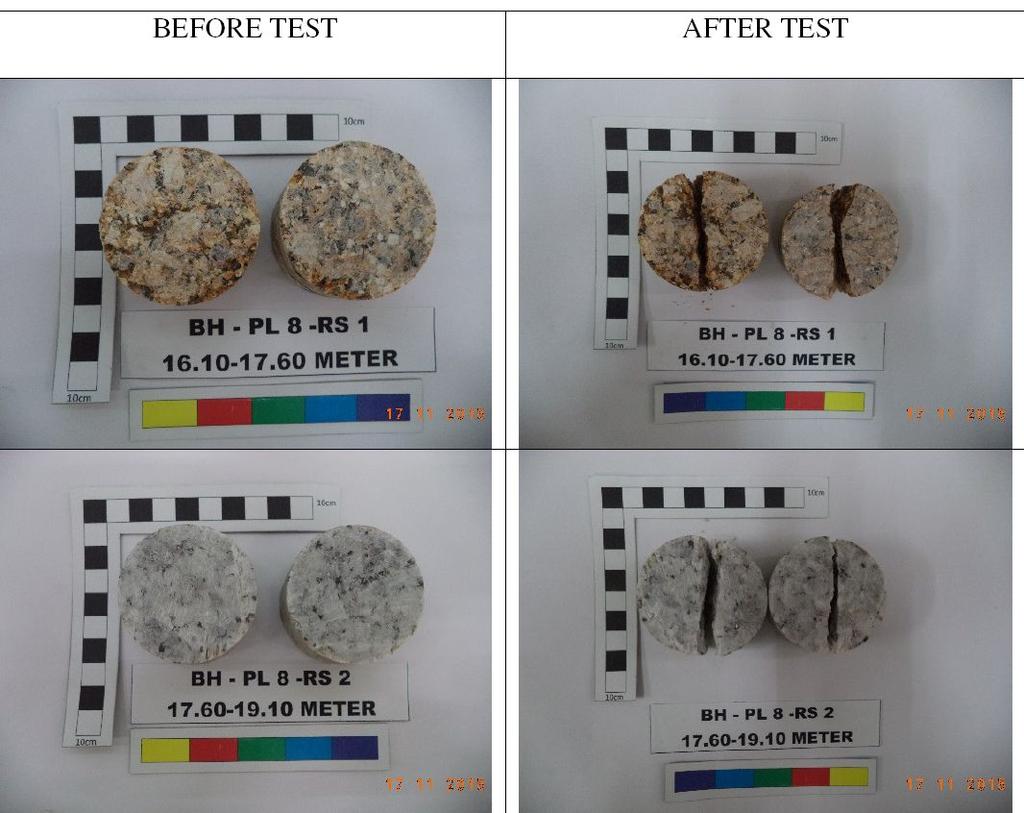
81 Failure under uniaxial compression test: Types and modes of failure of sample during testing indicate the degree of hardness & brittleness (kerapuhan) of rock. A number of characteristics can be interpreted about the sample tested. Under uniaxial compression, rock sample fails in a sudden manner & fracture planes (satah kegagalan) are distinctive. For strong rock like gabbro (igneous), crushed material (dust) and fragmentations is very minimal.
82 Failure under uniaxial compression test: For softer rock like shale (sedimentary rock), failure is gradual and fragmentation & powdered rock is more obvious. Fracture planes is less significant. Brittle (rapuh) & hard materials like rocks the strain at failure is relatively smaller & the stress at failure is higher. Mode and shape of failure are shown in Figure 7.6
83 Modes of failure of rock sample under loading

84 Fracture planes in failed rock sample

85 Fracture planes in failed rock sample (UCT)

86 Fracture planes in failed rock sample
")


87 (brittle) (ductile) Stress-strain curve for rock samples of different hardness: ductile and brittle

88

89 Triaxial compression test
90 Triaxial Compression test: Triaxial compression test (mampatan 3-paksi) is to evaluate the strength of rock under confinement (terkurung), e.g. rock samples obtained from deep seated rock mass (effect of hydrostatic pressure P = gh, due to weight of overburden). Rock displays a higher strength when confined and deformation behaviour becomes ductile / strainhardening).
91 Triaxial Compression test: The test is used to assess load bearing capability of rock at depth (20 m from surface). Example the bedrock (batu dasar) where a large structure is to be founded & strength of rock surrounding a deep tunnel. Test requires high capacity compression machine, Hoek s cell & confining pressure generator.
92 Overburden Surface Overburden stress P = gh. Deep seated rock intrusive igneous rock Rock body at depth is subjected to confining pressure, due to overburden stress & surrounding material
93 v h

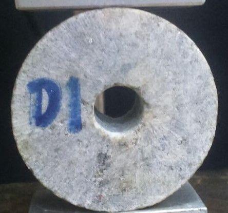
94 Hoek s Cell & sample sleeve for triaxial compression test on core sample of 54 mm D & 108 mm H

95 Hoek s Cell for use in triaxial compression test

96 Hoek s Cell for use in triaxial compression test
97 Test set-up for triaxial compression test

98 Compression machine Spherical seat Test set-up for triaxial compression test Hoek s cell with core sample Constant pressure pump unit with pressure accumulator
; data obtained is cohesion c & friction angle")
99 Mohr s circle is obtained from series of triaxal compression tests undertaken at different confining pressure ( 3 ); data obtained is cohesion c & friction angle

100 From the UCT Modes of failure of rock sample under loading
101 Triaxial tests on Indiana Limestone, showing transition from brittle fracture (at the low pressures) to ductile flow

102 Direct Shear Test
103 Direct shear test: Shear test is to evaluate shear strength & shear behaviour of weakness plane in rock (not shearing of the intact rock material) This is the most expensive laboratory strength tests, for it requires special method for acquiring of samples from site (fracture plane to be tested) & relatively complex testing procedures. Shear strength of the weakness planes (fractures & joint) in rock mass is important for project involving excavation in rock e.g. slope & tunnel.

104 Joint is the weakest point in this core sample, sliding or shearing is likely to occur along this fracture

105 Joint is the weakest point in this core sample, sliding or shearing is likely to occur along this fracture

106

107 NORMAL LOAD SHEAR LOAD
108 Direct shear test: Shear test is to obtain shear strength parameters : cohesion (c), basic friction angle ( ), & shear strength ( ). These parameters are greatly depending on the texture, roughness & degree of weathering of fracture surface being tested. Value of (dry) is between 30 0 (siltstone & slate) & 40 0 (limestone & basalt).

109

110 Portable shear box apparatus suitable for test on core sample (Roctest Phi 10)

111 Large shear box apparatus

112 Shear box section for rectangular sample size mm (H L B)

113 Shear box section for rectangular sample size mm (H L B)


114 TILT TEST
115 Estimation of joint shear strength: The shear joints will affect the stability of excavation face created in jointed rock mass. If sufficient information is available to allow realistic analysis of stability, then some quantitative assessment of joint strength is possible. The shear strength can be estimated perfectly adequately from the following formula, provided that exposed joint surfaces are available in situ, or at least in core samples. = n tan { JRC log 10 ( JCS / n ) b }
116 Estimation of joint shear strength: = n tan { JRC log 10 ( JCS / n ) b } : peak shear strength n : effective normal stress JRC: joint roughness coefficient JCS: joint wall compressive strength (obtained Rebound Hammer test on joint surface). b : is the basic friction angle (obtained from residual shear test on flat unweathered surfaces The shear strength estimated using the above formula includes apparent cohesion of the joint
117 Estimation of joint shear strength: In practice b may vary between 25 0 and 35 0, and the assumption of 30 0 will be adequate. JCS is obtained from Rebound Hammer test on joint surface and R is converted to JCS using formula: Log 10 JCS = (g) (R) ). (Broch & Franklin, JRC can be interpolated from roughness profile. A simpler, but more approximate means of estimating frictional shear strength (excluding apparent cohesion) is to take into account of the roughness using description given in the following table and add the basic friction angle.


118 Typical roughness profiles and JRC number
")
119 Sample of rectangular joint size mm (H L B)

120 Roughness of joint surface may induce dilation during shearing of joint blocks. Dilation is the vertical displacement that leads to joint opening.
121 Effect of surface texture (roughness) on shear strength


122 Roughness and frictional strength of joint Note: Slickenside on joint surfaces will reduce the angle of friction very considerably, and the presence of gouge or other infilling in the joint aperture may totally control the joint strength. In such cases, take the angle of friction to be 15 0.

123 Is 24 UCS Strength classification of rocks based on point load index strength (Broch & Franklin, 1972)


124 Durability Classification (Gamble, 1971)
")
125 Uniaxial compressive and tensile strengths of rocks (Pitts, 1984)


126 Typical static mechanical properties of some common rock types (Bengt Stillborg, 1985)


127 Typical engineering properties of rock


128 Classification of rock types based on unconfined compressive strength (McLean & Gribble, 1980)
129 J1 f' S1 g' S2 S3 f J2 g Core samples are obtained from rock drilling during SI. Cores are used to estimate RQD & suitable samples (core with fractures) are selected for laboratory shear tests


130

131 Split Hopkinson Pressure Bar (SHPB) SHPB consists of three bars: a striker bar, an incident bar, and a transmitted bar. The impact of the striker bar on the free end of the incident bar induces a longitudinal compressive wave propagating in both directions. The left propagating wave is fully released at the free end of the striker bar and forms the trailing edge of the incident compressive pulse εi. Strain gauges are used to record the stress wave pulse on both incident bar and transmitted bar.


132 Schematics of confined SHPB system for testing rocks (Frew et al., 2010). One of the objectives of an SHPB test is to determine the material dynamic stress-strain curve, from which the mechanical properties can be derived, e.g. dynamic failure strength, dynamic failure strain and dynamic Young s modulus.
133 Parameters affecting laboratory tests Factors affecting variations in test data include: Testing procedures used standard methods. Condition of sample sampling & preparations. Environment (lab test) temperature & humidity. Specimen size when small-scale discontinuities are present in sample (sedimentary & metamorphic rock).
")
134 Effect of loading orientation on UCS of sample displaying lamination (metamorphic rock e.g. schist)
 and due to metamorphism")

135 Minerals arrangements due to sedimentation (lamination) and due to metamorphism (foliation) are is small scale discontinuities rock (e.g. shale, sandstone slate & schist)

136 Being small scale discontinuities, they occur in laboratory rock sample. Fracture/failure can be easily induced along the lamination/foliation, but not perpendicular to it. Thus rock sample displaying lamination/foliation may display different strength when loaded at different direction
137 Effect of compressive strength due to anisotropy in Penrhyn slate


138 EXISTING FRACTURE AFECT FAILURE LOAD Effect of orientation of existing fracture on test data is more significant for Brazilian & Point-load test
139 Parameters affecting laboratory testing: Loading rate (kn/s), straining rate (%/s) & shearing rate (mm/s) higher loading rate, lower strength. Flatness & smoothness of specimen surfaces bending & flexural effect, cracks may initiate failure. For H/D greater than 2.0, UCS remains constant, thus the recommended H/D 2 to eliminate size effect. End-conditions affect UCS. The stronger the end platens (e.g. steel vs. graphite) the higher is the UCS (note: an important aspect in designing a pillars size in underground coal mining).
140 Ult. compr. strength (MPa) Effect of H/D ratio and end-platen on uniaxial compressive strength hardened steel as platens Rubber as paltens Graphite as platens height:diameter (H/D) Effect of H/D ratio and end-conditions
141 Parameters affecting laboratory testing: Stiffness of compression machine stiff loading column or machine equipped with closed-loop servo-controlled loading system to reduce sudden/violent post failure mode (violent failure is not inherent properties of rock). The state of stress remnant stress in rock mass may affect strength of rock sample obtained for laboratory test (cores obtained in folded rock strata) and deep-seated rock body.
142 Overburden Surface Overburden stress P = gh. Deep seated rock intrusive igneous rock Rock sample obtained from a deep-seated rock body (intrusive igneous rock) need to be test in a manner similar to its in-situ condition.
143 Discontinuities in rock & their effect on rock properties: Attached figure shows effect of single & multiple jointsets at different orientations, on compressive strength of rock. Rock normally exhibits multiple joint sets hence, it is weakened in all directions of loading. When the number of joint sets in a rock body approaches an infinite number (similar to soil body) the strength approaches that of soil strength (3 rd curve). Highly fractured rock displays a strength much lower than intact and unweathered rock.
 Effect of loading orientation on UCS of sample displaying lamination (metamorphic rock e.")
144 Stress versus strain Stress (MPa) Strain (%) Effect of loading orientation on UCS of sample displaying lamination (metamorphic rock e.g. schist)


 Existing fractures: leads to premature")
145 VARIATIONS ON ROCK PROPERTIES Samples variation: rock is inhomogeneous & anisotropic (contributes % error on lab data (Waltham, 2002) Machine accuracy: typically at 500 kn max. capacity, accuracy is 3 to 5 % (Jaeger & Cook, 1979) Existing fractures: leads to premature failure in some samples
146 Effect of water on rock strength: Sample saturation test at natural saturation (or either 100% saturation or dry). The presence of water & any increased pore water pressure (pwp) reduces rock strength. Water interrupts the bonding between minerals, and allows the break-up of clay cements in some sedimentary rocks. Water also acts as lubricant on fracture planes. PWP acts in opposition to confining stress; this reduces effective normal stress in triaxial situation, and therefore reduces confined shear strength. Water greatly reduces strength of weak, porous sedimentary rocks but has minimal effect on strong rock with low porosity.
147 Summary of various methods of calculation for Young s modulus.

148 Frequently asked questions Why joint is susceptible to weathering? If the surface of joint A is weathered to grade III, and joint B is grade I, which joint exhibits higher shear strength? If the surface roughness of joint A and B are of similar roughness, how weathering affects the shear strength of joint A? What test is used to measure the compressive strength of joint surface?

149 Typical loading configuration in rock testing
150 Discontinuities in rock & their effect on strength: Strength in rock refers to INTACT or material strength & MASS strength. Intact strength of rock depends on component mineral strength & the way they are bound together by interlocking or cementation. Strength normally determined in laboratory using small and fresh sample.
151 Discontinuities in rock & their effect on strength: Mass strength applies to a mass (or body) of fractured rock on site, hence also referred to as in situ strength. Mass strength largely relates to discontinuity (weakness) planes in rock. Mass strength also include effect of weathering (mass strength = intact strength + discontinuities + weathering + water condition). Strength normally determined in the field using in situ large-scale test. Strength data is affected by large-scale & small-scale discontinuities in sample.

152 Differences between rock mass (in situ) & rock material (intact) properties variation in properties due to the presence of discontinuities in rock
153 The influence of weakness planes on strength joint orientation with respect to loading axis
154 In situ or field test: Field or in situ tests are to assess properties of rock at location where they are found. Simple laboratory index tests (e.g. point-load & Rebound hammer) can also be undertaken on site as to save time & minimise disturbance of samples. Field test include large-scale direct strength tests undertaken on site. Tests require elaborate preparation & equipments & hence very expensive, complex & time consuming.

155 Texture of joint surface roughness (kekasaran)

156 Texture of joint surface (roughness)

157 Joint orientation that may contribute to rock sliding, note the typical profile of the joint
158 In lab tests it is important to note the direction of loading with respect to rock anisotropy. Strength of rock mass that exhibits small & largescale discontinuities is best assessed using largescale in-situ tests. Weathering also affects strength of rock. Degree of weathering is usually evaluated on site. In design, suitable FOS is used to cater for any uncertainty in design parameters (e.g. strength & E). Typical value of FOS is between 1.5 & 2.5. The higher the FOS, the more conservative is the design & subsequently, higher construction cost.

159 Fresh rock (weathering grade I)

160 Weathered rock (Gred V)
161 Properties of rock determined in laboratory & field: Take for example the effect of weathering, a difficult parameter to be accommodated and considered in designing a structure although its effect on rock properties is paramount. Sample use in laboratory strength test is usually fresh (grade I). On site, the rock body may be weathered. Therefore, a reduction factor must be imposed on to the laboratory data. This is similar to the use of F.O.S. in design, to cater for the uncertainty aspects & parameters that are difficult to measure.
 on strength of rock.")
162 Strength Reduction Factor (SRF): Effect of different weathering grades ( I to V) on strength of rock. Grade VI is soils
163 In situ or field test: In situ strength tests are undertaken when properties of rock is very critical to the design and detailed assessment under actual environment is essential. Most importantly, the cost justifies the importance of the data. The main advantages of field full-scale test are: 1) it involves a larger size of sample (inclusive of large-scale discontinuities 2) in situ sample is therefore undisturbed & more representative of field conditions.
164 In situ or field test: Among the common field tests are plate-bearing test & direct shear test. The complexity & elaborate preparation required to assess the shear behaviour of a rock block in slope & tunnel. The cost involved in undertaking the test can be seen in the anticipated behaviour of the unstable block with regard to nature of the project and surrounding rock mass.
![[a] & [b] shear test configuration; loading & displacement.](/docs-images/89/97640501/images/165-0.jpg "[c] & [d] type of shearing behaviour for unstable rock block in")
165 [a] & [b] shear test configuration; loading & displacement. [c] & [d] type of shearing behaviour for unstable rock block in different situations.

166 Plate load test
167 Direct shear test.
Rock Material. Chapter 3 ROCK MATERIAL HOMOGENEITY AND INHOMOGENEITY CLASSIFICATION OF ROCK MATERIAL
 Chapter 3 Rock Material In all things of nature there is something of the marvelous. Aristotle ROCK MATERIAL The term rock material refers to the intact rock within the framework of discontinuities. In
Module 5: Failure Criteria of Rock and Rock masses. Contents Hydrostatic compression Deviatoric compression
 FAILURE CRITERIA OF ROCK AND ROCK MASSES Contents 5.1 Failure in rocks 5.1.1 Hydrostatic compression 5.1.2 Deviatoric compression 5.1.3 Effect of confining pressure 5.2 Failure modes in rocks 5.3 Complete
PHYSICO-MECHANICAL PROPERTIES OF ROCKS LECTURE 2. Contents
 PHYSICO-MECHANICAL PROPERTIES OF ROCKS LECTURE 2 Contents 2.1 Introduction 2.2 Rock coring and logging 2.3 Physico-mechanical properties 2.3.1 Physical Properties 2.3.1.1 Density, unit weight and specific
SHEAR STRENGTH OF SOIL UNCONFINED COMPRESSION TEST
 SHEAR STRENGTH OF SOIL DEFINITION The shear strength of the soil mass is the internal resistance per unit area that the soil mass can offer to resist failure and sliding along any plane inside it. INTRODUCTION
STRENGTH PROPERTIES OF ROCKS AND ROCK MASSES 4. FAILURE CRITERIA FOR INTACT ROCKS AND ROCK MASSES
 STRENGTH PROPERTIES OF ROCKS AND ROCK MASSES 1. INTRODUCTION 2. TESTING OF INTACT ROCK FOR STRENGTH 2.1 Uniaxial Compression 2.2 Point Load Testing 2.3 Uniaxial Tension 2.4 Indirect Tension Tests 2.5 Shear
PLANES OF WEAKNESS IN ROCKS, ROCK FRCTURES AND FRACTURED ROCK. Contents
 PLANES OF WEAKNESS IN ROCKS, ROCK FRCTURES AND FRACTURED ROCK Contents 7.1 Introduction 7.2 Studies On Jointed Rock Mass 7.2.1 Joint Intensity 7.2.2 Orientation Of Joints 7.2.3 Joint Roughness/Joint Strength
MEMORANDUM SUBJECT: CERTIFICATE IN ROCK MECHANICS PAPER 1 : THEORY SUBJECT CODE: COMRMC MODERATOR: H YILMAZ EXAMINATION DATE: OCTOBER 2017 TIME:
 MEMORANDUM SUBJECT: CERTIFICATE IN ROCK MECHANICS PAPER 1 : THEORY EXAMINER: WM BESTER SUBJECT CODE: COMRMC EXAMINATION DATE: OCTOBER 2017 TIME: MODERATOR: H YILMAZ TOTAL MARKS: [100] PASS MARK: (60%)
Theory of Shear Strength
 MAJ 1013 ADVANCED SOIL MECHANICS Theory of Shear Strength Prepared by, Dr. Hetty 1 Strength of different materials Steel Concrete Soil Tensile strength Compressive strength Shear strength Complex behavior
Module 9 : Foundation on rocks. Content
 FOUNDATION ON ROCKS Content 9.1 INTRODUCTION 9.2 FOUNDATION TYPES ON ROCKS 9.3 BEARING CAPCITY- SHALLOW FOUNDATION 9.3.1 Ultimate bearing capacity 9.3.2 Safe bearing pressure 9.3.3 Estimation of bearing
Prof. B V S Viswanadham, Department of Civil Engineering, IIT Bombay
 56 Module 4: Lecture 7 on Stress-strain relationship and Shear strength of soils Contents Stress state, Mohr s circle analysis and Pole, Principal stressspace, Stress pathsin p-q space; Mohr-Coulomb failure
Boreholes. Implementation. Boring. Boreholes may be excavated by one of these methods: 1. Auger Boring 2. Wash Boring 3.
 Implementation Boreholes 1. Auger Boring 2. Wash Boring 3. Rotary Drilling Boring Boreholes may be excavated by one of these methods: 4. Percussion Drilling The right choice of method depends on: Ground
1.8 Unconfined Compression Test
 1-49 1.8 Unconfined Compression Test - It gives a quick and simple measurement of the undrained strength of cohesive, undisturbed soil specimens. 1) Testing method i) Trimming a sample. Length-diameter
Theory of Shear Strength
 SKAA 1713 SOIL MECHANICS Theory of Shear Strength Prepared by, Dr. Hetty 1 SOIL STRENGTH DEFINITION Shear strength of a soil is the maximum internal resistance to applied shearing forces The maximum or
Failure and Failure Theories for Anisotropic Rocks
 17th international Mining Congress and Exhibition of Turkey- IMCET 2001, 2001, ISBN 975-395-417-4 Failure and Failure Theories for Anisotropic Rocks E. Yaşar Department of Mining Engineering, Çukurova
Chapter (12) Instructor : Dr. Jehad Hamad
 Instructor : Dr. Jehad Hamad") Chapter (12) Instructor : Dr. Jehad Hamad 2017-2016 Chapter Outlines Shear strength in soils Direct shear test Unconfined Compression Test Tri-axial Test Shear Strength The strength of a material is the
Chapter (12) Instructor : Dr. Jehad Hamad 2017-2016 Chapter Outlines Shear strength in soils Direct shear test Unconfined Compression Test Tri-axial Test Shear Strength The strength of a material is the
SHEAR STRENGTH OF SOIL
 Soil Failure Criteria SHEAR STRENGTH OF SOIL Knowledge about the shear strength of soil important for the analysis of: Bearing capacity of foundations, Slope stability, Lateral pressure on retaining structures,
Chapter 5 Shear Strength of Soil
 Page 5 Chapter 5 Shear Strength of Soil. The internal resistance per unit area that the soil mass can offer to resist failure and sliding along any plane inside it is called (a) strength (b) shear strength
Lecture #2: Split Hopkinson Bar Systems
 Lecture #2: Split Hopkinson Bar Systems by Dirk Mohr ETH Zurich, Department of Mechanical and Process Engineering, Chair of Computational Modeling of Materials in Manufacturing 2015 1 1 1 Uniaxial Compression
Session 3: Geology and Rock Mechanics Fundamentals
 Session 3: Geology and Rock Mechanics Fundamentals Geotechnical Engineering Appreciation Course (Jointly organised by IES Academy and GeoSS) Dr Zhou Yingxin, Senior Principal Engineer, DSTA Adjuct Associate
Rock Mechanics Laboratory Tests for Petroleum Applications. Rob Marsden Reservoir Geomechanics Advisor Gatwick
 Rock Mechanics Laboratory Tests for Petroleum Applications Rob Marsden Reservoir Geomechanics Advisor Gatwick Summary A wide range of well established and proven laboratory tests are available for petroleum
Table 3. Empirical Coefficients for BS 8002 equation. A (degrees) Rounded Sub-angular. 2 Angular. B (degrees) Uniform Moderate grading.
 Rounded Sub-angular. 2 Angular. B (degrees) Uniform Moderate grading.") Hatanaka and Uchida (1996); ' 20N 20 12N 20 ' 45 A lower bound for the above equation is given as; 12N 15 ' 45 Table 3. Empirical Coefficients for BS 8002 equation A Angularity 1) A (degrees) Rounded 0
Hatanaka and Uchida (1996); ' 20N 20 12N 20 ' 45 A lower bound for the above equation is given as; 12N 15 ' 45 Table 3. Empirical Coefficients for BS 8002 equation A Angularity 1) A (degrees) Rounded 0
Quantitative Classification of Rock Mass
 Quantitative Classification of Rock Mass Description of Joints: Orientation, Persistence, Roughness, Wall Strength, Aperture, Filling, Seepage, Number of sets, Block size, spacing. ISRM commission s i
Chapter 12 Subsurface Exploration
 Page 12 1 Chapter 12 Subsurface Exploration 1. The process of identifying the layers of deposits that underlie a proposed structure and their physical characteristics is generally referred to as (a) subsurface
Laboratory Testing Total & Effective Stress Analysis
 SKAA 1713 SOIL MECHANICS Laboratory Testing Total & Effective Stress Analysis Prepared by: Dr. Hetty Mohr Coulomb failure criterion with Mohr circle of stress 2 ' 2 ' ' ' 3 ' 1 ' 3 ' 1 Cot Sin c ' ' 2
Soil Mechanics Brief Review. Presented by: Gary L. Seider, P.E.
 Soil Mechanics Brief Review Presented by: Gary L. Seider, P.E. 1 BASIC ROCK TYPES Igneous Rock (e.g. granite, basalt) Rock formed in place by cooling from magma Generally very stiff/strong and often abrasive
(Refer Slide Time: 02:18)
") Geology and Soil Mechanics Prof. P. Ghosh Department of Civil Engineering Indian Institute of Technology Kanpur Lecture 40 Shear Strength of Soil - C Keywords: Shear strength of soil, direct shear test,
Geology and Soil Mechanics Prof. P. Ghosh Department of Civil Engineering Indian Institute of Technology Kanpur Lecture 40 Shear Strength of Soil - C Keywords: Shear strength of soil, direct shear test,
Laboratory Triaxial and Permeability Tests on Tournemire Shale and Cobourg Limestone (Contract : R413.8) FINAL REPORT
 FINAL REPORT") RSP-413.8 Laboratory Triaxial and Permeability Tests on Tournemire Shale and Cobourg Limestone (Contract 87055-14-0209: R413.8) FINAL REPORT M.H.B. Nasseri, Ph.D and R.P. Young, Ph.D University of Toronto
RSP-413.8 Laboratory Triaxial and Permeability Tests on Tournemire Shale and Cobourg Limestone (Contract 87055-14-0209: R413.8) FINAL REPORT M.H.B. Nasseri, Ph.D and R.P. Young, Ph.D University of Toronto
DEVELOPMENT OF AUTOMATIC CONTROL OF MULTI-STAGE TRIAXIAL TESTS AT THE UNIVERSITY OF MISKOLC
 Geosciences and Engineering, Vol. 2, No. 3 (2013), pp. 37 43. DEVELOPMENT OF AUTOMATIC CONTROL OF MULTI-STAGE TRIAXIAL TESTS AT THE UNIVERSITY OF MISKOLC BALÁZS CSUHANICS ÁKOS DEBRECZENI Institute of Mining
SHEAR STRENGTH OF SOIL
 SHEAR STRENGTH OF SOIL Necessity of studying Shear Strength of soils : Soil failure usually occurs in the form of shearing along internal surface within the soil. Shear Strength: Thus, structural strength
ENGINEERING GEOLOGY AND ROCK MECHANICS
 ENGINEERING GEOLOGY AND ROCK MECHANICS SKAA 2712 ENGINEERING PROPERTIES OF ROCK MASSES PROF. MADYA DR. EDY TONNIZAM BIN MOHAMAD DEPT. OF GEOTECHNICS AND TRANSPORTATION FACULTY OF CIVIL ENGINEERING UTM
CHAPTER FIVE CLASSIFICATION OF SHEAR STRENGTH OF JOINTS IN ROCK
 CHAPTER FIVE CLASSIFICATION OF SHEAR STRENGTH OF JOINTS IN ROCK 5.1 Introduction The shear strength of joint surfaces in a rock mass is a difficult parameter to determine. Several researchers, including
Geology 229 Engineering and Environmental Geology. Lecture 5. Engineering Properties of Rocks (West, Ch. 6)
") Geology 229 Engineering and Environmental Geology Lecture 5 Engineering Properties of Rocks (West, Ch. 6) Outline of this Lecture 1. Triaxial rock mechanics test Mohr circle Combination of Coulomb shear
Geology 229 Engineering and Environmental Geology Lecture 5 Engineering Properties of Rocks (West, Ch. 6) Outline of this Lecture 1. Triaxial rock mechanics test Mohr circle Combination of Coulomb shear
8.1. What is meant by the shear strength of soils? Solution 8.1 Shear strength of a soil is its internal resistance to shearing stresses.
 8.1. What is meant by the shear strength of soils? Solution 8.1 Shear strength of a soil is its internal resistance to shearing stresses. 8.2. Some soils show a peak shear strength. Why and what type(s)
SOIL SHEAR STRENGTH. Prepared by: Dr. Hetty Muhammad Azril Fauziah Kassim Norafida
 SOIL SHEAR STRENGTH Prepared by: Dr. Hetty Muhammad Azril Fauziah Kassim Norafida What is shear strength Shear strength of a soil is the maximum internal resistance to applied shearing forces Why it is
Soil strength. the strength depends on the applied stress. water pressures are required
 Soil Strength Soil strength u Soils are essentially frictional materials the strength depends on the applied stress u Strength is controlled by effective stresses water pressures are required u Soil strength
Rock Mass Strength Characteristics at Manjung Area
 ICCBT2008 Rock Mass Strength Characteristics at Manjung Area N. I. Mohd Pauzi*, Universiti Tenaga Nasional, MALAYSIA R. Che Omar, Universiti Tenaga Nasional, MALAYSIA R. Roslan, Universiti Tenaga Nasional,
DESCRIPTION OF THE TESTS AND DATA USED IN THE CALIBRATION OF THE RMi
 From Palmström A.: RMi a rock mass characterization system for rock engineering purposes. PhD thesis, Oslo University, Norway, 1995, 400 p. APPENDIX 6 DESCRIPTION OF THE TESTS AND DATA USED IN THE CALIBRATION
Geology 229 Engineering Geology. Lecture 7. Rocks and Concrete as Engineering Material (West, Ch. 6)
") Geology 229 Engineering Geology Lecture 7 Rocks and Concrete as Engineering Material (West, Ch. 6) Outline of this Lecture 1. Rock mass properties Weakness planes control rock mass strength; Rock textures;
Geology 229 Engineering Geology Lecture 7 Rocks and Concrete as Engineering Material (West, Ch. 6) Outline of this Lecture 1. Rock mass properties Weakness planes control rock mass strength; Rock textures;
Simulation of the cutting action of a single PDC cutter using DEM
 Petroleum and Mineral Resources 143 Simulation of the cutting action of a single PDC cutter using DEM B. Joodi, M. Sarmadivaleh, V. Rasouli & A. Nabipour Department of Petroleum Engineering, Curtin University,
Effect of intermediate principal stresses on compressive strength of Phra Wihan sandstone
 Rock Mechanics, Fuenkajorn & Phien-wej (eds) 211. ISBN 978 974 533 636 Effect of intermediate principal stresses on compressive strength of Phra Wihan sandstone T. Pobwandee & K. Fuenkajorn Geomechanics
LECTURE NO. 4-5 INTRODUCTION ULTRASONIC * PULSE VELOCITY METHODS
 LECTURE NO. 4-5 ULTRASONIC * PULSE VELOCITY METHODS Objectives: To introduce the UPV methods To briefly explain the theory of pulse propagation through concrete To explain equipments, procedures, calibrations,
Wikipedia.org BUILDING STONES. Chapter 4. Materials of Construction-Building Stones 1
 Wikipedia.org BUILDING STONES Chapter 4 Materials of Construction-Building Stones 1 What is Stone? Stone is a concretion of mineral matter. Used either as a; Construction material, Manufacture of other
SITE INVESTIGATION 1
 SITE INVESTIGATION 1 Definition The process of determining the layers of natural soil deposits that will underlie a proposed structure and their physical properties is generally referred to as site investigation.
SOIL MECHANICS SAB1713 DR. HETTY
 SOIL MECHANICS SAB1713 DR. HETTY INTRODUCTION SOIL MECHANICS -Concerned solely with soils -Concerned with the deformation and strength of bodies of soils -Concerned with the interaction of structures with
SYLLABUS AND REFERENCES FOR THE STRATA CONTROL CERTIFICATE COAL MINING OPTION
 CHAMBER OF MINES OS SOUTH AFRICA SYLLABUS AND REFERENCES FOR THE STRATA CONTROL CERTIFICATE COAL MINING OPTION 1. PART 1 : THEORY 1.1 Basic principles of rock engineering 1.1.1 Terms, definitions and basic
Supplementary Uniaxial Compressive Strength Testing of DGR-3 and DGR-4 Core
 Technical Report Title: Document ID: Authors: Supplementary Uniaxial Compressive Strength Testing of DGR-3 and DGR-4 Core TR-08-39 B. Gorski, T. Anderson and D. Rodgers CANMET Mining and Mineral Sciences
Rock Mechanics and Seismology Laboratory
 CAEE 211 Geology Laboratory 6 Lab Date: 29 July 2016 Rock Mechanics and Seismology Laboratory Due Date: 5 August 2016 Attendance (based on signing): 30 points Submitting Student Name: Members of laboratory
LAB 2 IDENTIFYING MATERIALS FOR MAKING SOILS: ROCK AND PARENT MATERIALS
 LAB 2 IDENTIFYING MATERIALS FOR MAKING SOILS: ROCK AND PARENT MATERIALS Learning outcomes The student is able to: 1. understand and identify rocks 2. understand and identify parent materials 3. recognize
Module 9 : Foundation on rocks
 LECTURE 32 9.3 BEARING CAPCITY contd... 9.3.2 Safe bearing pressure There are different methods are available to determine the safe bearing pressure on rocks. However, the applicability of different methods
CONCRETE TECHNOLOGY LABORATORY
 CONCRETE TECHNOLOGY LABORATORY DEPARTMENT OF CIVIL ENGINEERING CHULALONGKORN UNIVERSITY Tested by... ID No.... Date... Graded by... TEST No. C-7 NON-DESTRUCTIVE TEST OF HARDENED CONCRETE Part A Pulse Velocity
An introduction to the Rock Mass index (RMi) and its applications
 and its applications") Reference: A. Palmström, www.rockmass.net An introduction to the Rock Mass index (RMi) and its applications by Arild Palmström, Ph.D. 1 Introduction Construction materials commonly used in civil engineering
Reference: A. Palmström, www.rockmass.net An introduction to the Rock Mass index (RMi) and its applications by Arild Palmström, Ph.D. 1 Introduction Construction materials commonly used in civil engineering
Reservoir Rock Properties COPYRIGHT. Sources and Seals Porosity and Permeability. This section will cover the following learning objectives:
 Learning Objectives Reservoir Rock Properties Core Sources and Seals Porosity and Permeability This section will cover the following learning objectives: Explain why petroleum fluids are found in underground
Manual on Subsurface Investigations National Highway Institute Publication No. FHWA NHI Federal Highway Administration Washington, DC
 Manual on Subsurface Investigations National Highway Institute Publication No. FHWA NHI-01-031 Federal Highway Administration Washington, DC Geotechnical Site Characterization July 2001 by Paul W. Mayne,
Geomechanical Characterization of a Montney Equivalent Outcrop
 Is (MPa) Geomechanical Characterization of a Montney Equivalent Outcrop Scott H McKean, Mason MacKay, Dr. Jeffrey Priest University of Calgary Summary A variety of geomechanical tests (point load strength,
ROCK MASS PROPERTIES FOR TUNNELLING
 ROCK MASS PROPERTIES FOR TUNNELLING Robert Bertuzzi 2 nd November 2017 1 Driver Estimating the strength and deformation characteristics of a rock mass for tunnel design is generally based on empiricism
Critical Borehole Orientations Rock Mechanics Aspects
 Critical Borehole Orientations Rock Mechanics Aspects By R. BRAUN* Abstract This article discusses rock mechanics aspects of the relationship between borehole stability and borehole orientation. Two kinds
Shear Strength of Soils
 Shear Strength of Soils STRESSES IN A SOIL ELEMENT t s v Analyze Effective Stresses (s ) Load carried by Soil t Where: s H t t s H s = t f = s v = s H = t = s v Stresses in a Soil Element after Figure
ENGINEERING GEOLOGY AND ROCK ENGINEERING
 1 ENGINEERING GEOLOGY AND ROCK ENGINEERING HANDBOOK NO. 2 Norwegian Group for Rock Mechanics (NBG) www.bergmekanikk.com Prepared in co-operation with Norwegian Tunnelling Society (NFF) Issued in 2000 SECRETARIAT:
D1. A normally consolidated clay has the following void ratio e versus effective stress σ relationship obtained in an oedometer test.
 (d) COMPRESSIBILITY AND CONSOLIDATION D1. A normally consolidated clay has the following void ratio e versus effective stress σ relationship obtained in an oedometer test. (a) Plot the e - σ curve. (b)
A Constitutive Framework for the Numerical Analysis of Organic Soils and Directionally Dependent Materials
 Dublin, October 2010 A Constitutive Framework for the Numerical Analysis of Organic Soils and Directionally Dependent Materials FracMan Technology Group Dr Mark Cottrell Presentation Outline Some Physical
Lecture 5. Rheology. Earth Structure (2 nd Edition), 2004 W.W. Norton & Co, New York Slide show by Ben van der Pluijm
, 2004 W.W. Norton & Co, New York Slide show by Ben van der Pluijm") Lecture 5 Rheology Earth Structure (2 nd Edition), 2004 W.W. Norton & Co, New York Slide show by Ben van der Pluijm WW Norton; unless noted otherwise Rheology is... the study of deformation and flow of
Lecture 5 Rheology Earth Structure (2 nd Edition), 2004 W.W. Norton & Co, New York Slide show by Ben van der Pluijm WW Norton; unless noted otherwise Rheology is... the study of deformation and flow of
NORMAL STRESS. The simplest form of stress is normal stress/direct stress, which is the stress perpendicular to the surface on which it acts.
 NORMAL STRESS The simplest form of stress is normal stress/direct stress, which is the stress perpendicular to the surface on which it acts. σ = force/area = P/A where σ = the normal stress P = the centric
SCOPE OF INVESTIGATION Simple visual examination of soil at the surface or from shallow test pits. Detailed study of soil and groundwater to a
 Lecture-5 Soil Exploration Dr. Attaullah Shah 1 Today s Lecture Purpose of Soil Exploration Different methods 1. Test trenches and Pits 2. Auger and Wash Boring 3. Rotary Drilling 4. Geophysical Methods
DEM simulation of fracture process of inherently anisotropic rock under Brazilian test condition
 Title DEM simulation of fracture process of inherently anisotropic rock under Brazilian test condition Author(s) Kwok, CY; Duan, K Citation The 49th US Rock Mechanics / Geomechanics Symposium, San Francisco,
1.103 CIVIL ENGINEERING MATERIALS LABORATORY (1-2-3) Dr. J.T. Germaine Spring 2004 LABORATORY ASSIGNMENT NUMBER 6
 Dr. J.T. Germaine Spring 2004 LABORATORY ASSIGNMENT NUMBER 6") 1.103 CIVIL ENGINEERING MATERIALS LABORATORY (1-2-3) Dr. J.T. Germaine MIT Spring 2004 LABORATORY ASSIGNMENT NUMBER 6 COMPRESSION TESTING AND ANISOTROPY OF WOOD Purpose: Reading: During this laboratory
1.103 CIVIL ENGINEERING MATERIALS LABORATORY (1-2-3) Dr. J.T. Germaine MIT Spring 2004 LABORATORY ASSIGNMENT NUMBER 6 COMPRESSION TESTING AND ANISOTROPY OF WOOD Purpose: Reading: During this laboratory
Sand Control Rock Failure
 Sand Control Rock Failure Why? A bit of Mechanics on rock failure How? Some choices that depend on the rock What is moving? Sand grains? Fines? 3/14/2009 1 Young s Modulus, E Young s Modulus is a material
Chapter 6 Bearing Capacity
 Chapter 6 Bearing Capacity 6-1. Scope This chapter provides guidance for the determination of the ultimate and allowable bearing stress values for foundations on rock. The chapter is subdivided into four
Rock Mechanics and Rock Engineering
 Rock Mechanics and Rock Engineering Overview Rock mechanics is the theoretical and applied science of the mechanical behaviour of rock and rock masses. Rock mechanics deals with the mechanical properties
Chapter. Materials. 1.1 Notations Used in This Chapter
 Chapter 1 Materials 1.1 Notations Used in This Chapter A Area of concrete cross-section C s Constant depending on the type of curing C t Creep coefficient (C t = ε sp /ε i ) C u Ultimate creep coefficient
Soil and Rock Strength. Chapter 8 Shear Strength. Steel Strength. Concrete Strength. Dr. Talat Bader May Steel. Concrete.
 Chapter 8 Shear Strength Dr. Talat Bader May 2006 Soil and Rock Strength Unconfined compressive strength (MPa) Steel Concrete 20 100 250 750 0.001 0.01 Soil 0.1 1.0 10 Rock 100 250 F y = 250 to 750 MPa
6/20/2018. Lesson 1 (Properties of Minerals) 6 th Grade. Earth s Structure Chapter 2: Minerals and Rocks. density =
 6 th Grade. Earth s Structure Chapter 2: Minerals and Rocks. density =") 6 th Grade Earth s Structure Chapter 2: Minerals and Rocks Mineral Lesson 1 (Properties of Minerals) a mineral must meet all four of the following requirements: 1. must be naturally-occurring (formed by
6 th Grade Earth s Structure Chapter 2: Minerals and Rocks Mineral Lesson 1 (Properties of Minerals) a mineral must meet all four of the following requirements: 1. must be naturally-occurring (formed by
Pullout Tests of Geogrids Embedded in Non-cohesive Soil
 Archives of Hydro-Engineering and Environmental Mechanics Vol. 51 (2004), No. 2, pp. 135 147 Pullout Tests of Geogrids Embedded in Non-cohesive Soil Angelika Duszyńska, Adam F. Bolt Gdansk University of
APPENDIX A. Borehole Logs Explanation of Terms and Symbols
 APPENDIX A Borehole Logs Explanation of Terms and Symbols Page 153 of 168 EXPLANATION OF TERMS AND SYMBOLS The terms and symbols used on the borehole logs to summarize the results of field investigation
Module 6: Stresses around underground openings. 6.2 STRESSES AROUND UNDERGROUND OPENING contd.
 LECTURE 0 6. STRESSES AROUND UNDERGROUND OPENING contd. CASE : When σ x = 0 For σ x = 0, the maximum tangential stress is three times the applied stress and occurs at the boundary on the X-axis that is
Hardened Concrete. Lecture No. 16
 Hardened Concrete Lecture No. 16 Fatigue strength of concrete Modulus of elasticity, Creep Shrinkage of concrete Stress-Strain Plot of Concrete At stress below 30% of ultimate strength, the transition
Numerical modeling of standard rock mechanics laboratory tests using a finite/discrete element approach
 Numerical modeling of standard rock mechanics laboratory tests using a finite/discrete element approach S. Stefanizzi GEODATA SpA, Turin, Italy G. Barla Department of Structural and Geotechnical Engineering,
PREDICTION OF THE MECHANICAL PROPERTIES OF GRANITES BY ULTRASONIC PULSE VELOCITY AND SCHMIDT HAMMER HARDNESS. Introduction
 998 Papers contained in these Proceedings have been reviewed in accordance with the policies of The Masonry Society PREDICTION OF THE MECHANICAL PROPERTIES OF GRANITES BY ULTRASONIC PULSE VELOCITY AND
Minerals. What are minerals and how do we classify them?
 Minerals What are minerals and how do we classify them? 1 Minerals! Minerals are the ingredients needed to form the different types of rocks! Rock - is any naturally formed solid that is part of Earth
An Experimental Characterization of the Non-linear Rheology of Rock
 An Experimental Characterization of the Non-linear Rheology of Rock G. N. BorrNoTr New England Research Inc. Contract: F49620-95-C-0019 Sponsor: AFOSR ABSTRACT A laboratory experimental program is underway
8. STRENGTH OF SOILS AND ROCKS
 8-1 8. STRENGTH OF SOILS AND ROCKS 8.1 COMPRESSIVE STRENGTH The strength of a material may be broadly defined as the ability of the material to resist imposed forces. If is often measured as the maximum
SOME OBSERVATIONS RELATED TO LIQUEFACTION SUSCEPTIBILITY OF SILTY SOILS
 SOME OBSERVATIONS RELATED TO LIQUEFACTION SUSCEPTIBILITY OF SILTY SOILS Upul ATUKORALA 1, Dharma WIJEWICKREME 2 And Norman MCCAMMON 3 SUMMARY The liquefaction susceptibility of silty soils has not received
Pre-failure Deformability of Geomaterials. Hsin-yu Shan Dept. of Civil Engineering National Chiao Tung University
 Pre-failure Deformability of Geomaterials Hsin-yu Shan Dept. of Civil Engineering National Chiao Tung University Strain Levels Strain at failure Sand Clay Rock Distribution of strain of soil in the field
Triaxial Shear Test. o The most reliable method now available for determination of shear strength parameters.
 TOPICS Introduction Components of Shear Strength of Soils Normal and Shear Stresses on a Plane Mohr-Coulomb Failure Criterion Laboratory Shear Strength Testing Direct Shear Test Triaxial Compression Test
Underground Excavation Design Classification
 Underground Excavation Design Underground Excavation Design Classification Alfred H. Zettler alfred.zettler@gmx.at Rock Quality Designation Measurement and calculation of RQD Rock Quality Designation index
Standard Test Method for Determination of the Point Load Strength Index of Rock 1
 Designation: D 5731 95 AMERICAN SOCIETY FOR TESTING AND MATERIALS 100 Barr Harbor Dr., West Conshohocken, PA 19428 Reprinted from the Annual Book of ASTM Standards. Copyright ASTM Standard Test Method
Ch 4a Stress, Strain and Shearing
 Ch. 4a - Stress, Strain, Shearing Page 1 Ch 4a Stress, Strain and Shearing Reading Assignment Ch. 4a Lecture Notes Sections 4.1-4.3 (Salgado) Other Materials Handout 4 Homework Assignment 3 Problems 4-13,
Earth Science Chapter 6 Rocks
 Earth Science Chapter 6 Rocks I. Rocks and the Rock Cycle * Material that makes up the solid part of the Earth. * Made of a variety of different combinations of minerals and organic matter. A. Three Major
CHAPTER 3 EXPERIMENTAL STUDY
 Experimental Study 42 CHAPTER 3 EXPERIMENTAL STUDY 3.1. INTRODUCTION The experimental study that has been carried out in this thesis has two main objectives: 1. Characterise the concrete behaviour in mode
Engineering materials
 1 Engineering materials Lecture 9 Aggregates 2 Composition and structure Natural aggregates are derived from rocks. Classification: Igneous( 火成岩 ), sedimentary ( 沉積岩 ) and metamorphic ( 變質岩 ) Fine or coarse
(Refer Slide Time 1:07 min)
") Soil Mechanics Prof. B.V.S. Viswanathan Department of Civil Engineering Indian Institute of Technology, Bombay Lecture 46 Shear Strength of Soils Lecture No.4 Students we had 3 lectures so far on this
Soil Mechanics Prof. B.V.S. Viswanathan Department of Civil Engineering Indian Institute of Technology, Bombay Lecture 46 Shear Strength of Soils Lecture No.4 Students we had 3 lectures so far on this
7. Foundation and Slope Stability
 The Asian Nuclear Safety Network 7. Foundation and Slope Stability (SER 2.5.4 & 2.5.5) Taek-Mo SHIM k147stm@kins.re.kr Korea Institute of Nuclear Safety Structural Systems and Site Evaluation Department
Numerical models on anisotropy of rocks
 NGM 206 Reykjavik Proceedings of the 7 th Nordic Geotechnical Meeting Challenges in Nordic Geotechnic 25 th 28 th of May Numerical models on anisotropy of rocks Henok M. Kassa Statoil ASA, Norway, hmka@statoil.com
Rock Failure. Topics. Compressive Strength Rock Strength from Logs Polyaxial Strength Criteria Anisotropic Rock Strength Tensile Strength
 Rock Failure Topics Compressive Strength Rock Strength from Logs Polyaxial Strength Criteria Anisotropic Rock Strength Tensile Strength Key Points 1. When rock fails in compression, the compressive stress
Table of Contents Chapter 1 Introduction to Geotechnical Engineering 1.1 Geotechnical Engineering 1.2 The Unique Nature of Soil and Rock Materials
 Table of Contents Chapter 1 Introduction to Geotechnical Engineering 1.1 Geotechnical Engineering 1.2 The Unique Nature of Soil and Rock Materials 1.3 Scope of This Book 1.4 Historical Development of Geotechnical
Numerical modelling for estimation of first weighting distance in longwall coal mining - A case study
 University of Wollongong Research Online Coal Operators' Conference Faculty of Engineering and Information Sciences 2012 Numerical modelling for estimation of first weighting distance in longwall coal
ON THE FACE STABILITY OF TUNNELS IN WEAK ROCKS
 33 rd 33 Annual rd Annual General General Conference conference of the Canadian of the Canadian Society for Society Civil Engineering for Civil Engineering 33 e Congrès général annuel de la Société canadienne
Main Means of Rock Stress Measurement
 Real Stress Distributions through Sedimentary Strata and Implications for Reservoir Development and Potential Gas and Coal Development Strategies Ian Gray Sigra Pty Ltd 93 Colebard St West, Acacia Ridge,
Sabah Shawkat Cabinet of Structural Engineering Walls carrying vertical loads should be designed as columns. Basically walls are designed in
 Sabah Shawkat Cabinet of Structural Engineering 17 3.6 Shear walls Walls carrying vertical loads should be designed as columns. Basically walls are designed in the same manner as columns, but there are
Entrance exam Master Course
 - 1 - Guidelines for completion of test: On each page, fill in your name and your application code Each question has four answers while only one answer is correct. o Marked correct answer means 4 points
THE VOUSSOIR BEAM REACTION CURVE
 THE VOUSSOIR BEAM REACTION CURVE Yossef H. Hatzor Ben-Gurion University, Department of Geological and Environmental Sciences Beer-Sheva, Israel, 84105 ABSTRACT: The influence of joint spacing (s) on the