o l>!^ AUGUST NUMBER 14 USE OF SHALE IN EMBANKMENTS LOVELL, JR. JOINT HIGHWAY RESEARCH PROJECT PURDUE UNIVERSITY AND C.W. L. E.
|
|
|
- Leon Richardson
- 5 years ago
- Views:
Transcription


1 USE OF SHALE IN EMBANKMENTS AUGUST NUMBER 14 o l>!^ P. DEO L. E. WOOD C.W. LOVELL, JR. JOINT HIGHWAY RESEARCH PROJECT PURDUE UNIVERSITY AND INDIANA STATE HIGHWAY COMMISSION

2


3 1 USE OF SHALE IN EMBANKMENTS AUGUST NUMBER 14 #*^ j/ (tf #Wi; ;?i i R DEO L. E. WOOD C.W. LOVELL, JR. JOINT HIGHWAY RESEARCH PROJECT PURDUE UNIVERSITY AND INDIANA STATE HIGHWAY COMMISSION

4


5 Technical Paper USE OF SHALE IN EMBANKMENTS TO: J. F. McLaughlin, Director August 29, 1973 Joint Highway Research Project Project: C-36-5J FROM: H. L. Michael, Associate Director Joint Highway Research Project File: The attached Technical Paper "Use of Shale in Embankments" has been authored by Messrs. P. Deo, L. E. Wood and C. W. Lovell, Jr., former or present members of our staff. The paper is from the research conducted by Mr. Deo, directed by Professors Wood and Lovell and reported in J.H.R.P. Report No. 45, 1972, titled "Shales as Embankment Materials". The paper will be presented at the Summer Meeting of the Highway Research Board to be held in Olympia, Washington in early August It is presented to the Board for approval of publication as it is planned for such action by the Highway Research Board. Respectfully submitted, Harold L. Associate Michael Director HLM:ms cc: W. L. Dolch R. H. Harrell C. F. Scholer R. L. Eskew M. L. Hayes M. B. Scott G. D. Gibson C. W. Lovell J. A. Spooner W. H, Goetz G. W. Marks N. W. Steinkamp M. J. Gutzwiller R. D. Miles H. R. J. Walsh G. T. Satterly E. J. Yoder
 L. E. Wood, Associate Professor of Engineering C.")

6 Technical Paper USE OF SHALE IN EMBANKMENTS by P. Deo, Soils Engineer, American Testing and Engineering Corporation (formerly Graduate Assistant in Research at Purdue University) L. E. Wood, Associate Professor of Engineering C. W. Lovell, Jr., Professor of Civil Engineerinj Joint Highway Research Project Project No. : C-36-5J File No.: Conducted by Joint Highway Research Project Engineering Experiment Station Purdue University In Cooperation With Indiana State Highway Commission Purdue University West Lafayette, Indiana August 1973

 into soil in service.")
7 USE OF SHALE IN EMBANKMENTS ABSTRACT Guidelines for the design and construction of soil embankments are sufficiently developed so that unsatisfactory performance by these fills is relatively rare. The same is true for rock fills, where the sound and durable rock is placed in large chunks, and with large voids between the chunks. However, there are transition materials or "soft rocks" for which placement in large chunks may lead to highly unsatisfactory embankment performance. Shales afford the prominent example, since the large pieces may degrade (slake) into soil in service. This soil may in turn sift down into the large voids, with the net result that large settlements, and even slope instability, may occur. Embankment failure due to the above mentioned circumstances resulted in closing lanes on Interstate 74 in Indiana and required costly repairs. Similar failures have occurred in other states in the midwest. The harder and more durable shales can probably be placed as rock fills with certain safeguards. The shales of very low durability must be throughly degraded at the end of compaction, i.e., must be treated as Soil fills. A full spectrum of durabilities exists between these limits. The engineer obviously needs a classification system which will establish where, in the possible range of relative durabilities, a potential embankment shale lies.

8 il To develop such a classification for Indiana shales, materials were sampled and subjected to a battery of durability, stability and miscelleneous type tests. The durability tests were those used as standard for mineral aggregates, but modified in severity to account for the "soft rock" being evaluated. It was concluded that the desired classification into four groupings, viz., soil-like, intermediate-1, intermediate-2, and rock-like shales, could be accomplished with no more than four rather simple tests: one cycle slaking in water, slakedurability on an initially dry sample, slake-durability on a soaked sample, and a modified sodium sulfate soundness test. The paper describes the Indiana shales tested, the tests proper, and the response of the Indiana shales in the tests. It concludes with a flow chart showing how the tests are used to accomplish the shale classification.

9 USE OF SHALE IN EMBANKMENTS INTRODUCTION Highways embankments are commonly built with soil, and less commonly with rock. However in either case, design standards and construction specifications are backed with sufficient experience to be applied with confidence. But how about the family of constructional materials which is transitional between soil and rock, viz., the "soft rocks". Soft rocks include all types of mudrock, which is any sedimentary rock containing at least 50% silt and clay constituents. Mudrock is thus a general name for all varities of siltrocks, clayrocks, mudstones, siltstones, mudshales, silt shales, clay shales and argillites. Twenhofel (14), Underwood (15), Ingram (9), and Gamble (6) have differentiated among these rocks. Figure 1 is an example. This paper concentrates on the shales. When shales are used as embankment materials in the central U.S., the engineer tends to view them with suspicion, and often recommends design and construction procedures which are conservative, e.g., extra rolling to fragment the material, placing another material between the shale and the atmosphere (encasement), flattening slopes, special attention to surface and subsurface drainage, and using berms. These procedures have reduced, but not eliminated, instabilities of shale embankments (8, 12, 16). However, it is probable that the current practice is generally too conservative, e.g., some relatively high quality shales are being unnecessarily degraded and placed as soil fill. Items in parentheses refer to entries in the Bibliography.


10 2. UNINDURATED INDURATED AFTER INCIPIENT METAMORPHISM METAMORPHIC EQUIVALENT Mudstone -* Silt Siltstone \ '+H 2 / Clay = Mud / Fissility = Shale Claystone. Argillite Slate Phillite Schist FIGURE I - CLASSIFICATION OF SHALE AND RELATED ROCKS (1 4).

11 :.. It 1b suggested that shales can be grouped in the following four categories. 1. Shales which are highly susceptible to post-constructional degradation and when so reduced are actually inferior in performance to normal fine grained soils. The use of these materials in embankments should be restricted. 2. Shales which are about "at par" with normal fine grained soils and may be used with common soil design and construction controls, if they are rather thoroughly degraded in the construction process 3. Shales which are imperfectly degraded in the construction process, and which will be only slightly degraded in service, are stronger than soils, yet cannot be placed as rockfill. U. Shales which are very difficult to degrade can likely be placed as rockfills. These materials are intrinsically superior to soil in fills if certain construction problems can be overcome. This paper reviews the current placement technology for shale embankments and suggests a simple and inexpensive testing program to classify the shales with respect to their use in embankments PROBLEMS WITH SHALES AS EMBANKMENT MATERIALS Potential problems within an embankment constructed with shales include a. Settlement due to loading, drying, slaking, or thawing. 1. Slaking is the process through which a material disintegrates or crumbles into small particulate units when exposed to moisture, and especially when dried and immersed in water.


12 . k. b. Heave caused by wetting or freezing. c. Slope instability. d. Surface and subsurface erosion. The degree to which soft rocks will demonstrate poor performance depends largely on their service environment, both man-made and natural. For example, unless the material becomes significantly wetter than the placement condition, slaking may not occur. Once exposed to increased moisture, slaking may occur quickly, in many years, or not at all. The practical consequence of the slaking, if it occurs, depends primarily upon the relative abundance of large voids in the compacted mass, into which the slaked material can settle. The size and frequency of large voids is rather directly related, in turn, to the relative abundance of large chunks of shale in the embankment. If large chunks of slaking materials are placed in the embankment, major problems can be anticipated. If on the other hand, the slaking material is reduced to small pieces in the construction process, the subsequent slaking in service may produce no unacceptable densifi cations or surface displacements. Degradation of material in the embankment can be controlled by effective drainage and/ or proper encasement of the embankments. Even relatively nonslaking materials are weakened and made more compressible by increased moisture. Other shales contain enough expansive minerals to cause significant swelling upon wetting and shrinkage upon drying, with potentially harmful effects on the embankment and/or the overlying pavement If one is able to assess the general susceptibility of a material to slaking, volume change, and the like, in the projected service

13 environment, more rationed, decisions can be reached in the design and construction processes, thereby increasing the probability that satisfactory service will be produced with economy. CURRENT PLACEMENT TECHNOLOGY Shales have been treated sometimes as a soil, sometimes as a rock in embankments. Sherard and others (12) emphasize the importance of proper investigation of these materials and handling each as an individual problem. Test embankment sections are recommended, where possible. The various agencies constructing embankments have separate specifications for soils and rocks. However, there may be no fixed specifications for shale or other soft rocks embankments. The Indiana State Highway Commission uses shales in embankments with the following provisions 1. Shales are subjected to thorough breakdown in the process of excavation, hauling, placement and compaction; in other words, treated like soil fill. Occasionally, lift thicknesses are made even thinner than for soil. 2. A non-shale soil encasement of two or three feet is provided on all boundaries of the embankment. 3. The shale-soil mixture, when treated in the specified manner, is considered to be highly competent, and no other special design features are needed. Such provisions are normally contained in a special construction specification statement, and are often quite qualitative.
 shales are recognized, but there are no quantitative criteria to indicate into which group the shale in question should fall.")
14 6. Some agencies, including the Soil Conservation Service in Indiana, use shale in the construction of small dams (13). Durable and nondurable (soil-like) shales are recognized, but there are no quantitative criteria to indicate into which group the shale in question should fall. In Indiana the SCS has used shales with the following provisions: Durable Shales. 1. The maximum size of rock fragments used is eighteen inches, provided that such fragments are completely embedded in a matrix of compacted fill. 2. The maximum thickness of rock layers before compaction 1b twenty-four inches. 3. Broken shale and limestone mixtures may be used in rock fill. 4. Rock fill has a cover of weathering resistant material of two to four feet. 5. A minimum compacted dry unit weight of pcf was used for two different shales. This number could vary for other shales (13). Soil-like Shales. 1. A shale which completely slakes in water in a few (about ten) minutes can also be used in embankment provided it is thoroughly broken down to soil during excavation, hauling, placement, and compaction. 2. A minimum encasement of four feet of non-shale soil is needed. 3. The unit weight of the fill should be at least 95 percent of the maximum determined by ASTM D T, Moisture-Density Relations of Soils (3). With the current state of the art in the midwestern U.S., a considerable amount of judgment may be required at the time of construction, and there is a definite potential for being unduly conservative, and even

15 7. occasionally, erring on the unsafe side. ENGINEERING CLASSIFICATION OF SHALES There is a need In the midwest to develop a simple and Inexpensive testing routine to classify shales with respect to their suitability for use in embankments. With this objective, representative samples of shales were collected from fifteen different locations within the state of Indiana, see Figure 2. These materials covered a wide behavioral spectrum, from very hard and durable ones to those which rapidly weather into soil. The testing which was conducted in the laboratory can be grouped into four categories. a) Degradation Type Tests measured slaking and other breakdown of the material. As the standard tests were inappropriate for soft rocks, it was necessary to develop new ones, or at least to modify existing ones. This group includes different types of slaking tests (in air, water, and sodium sulfate solution) and abrasion tests. b) Soil-Type Standard Identification Tests were conducted on the shales in a thoroughly degraded condition. This group included Atterberg limits, grain size distribution and X-ray diffraction. c) Compaction and Load-Deformation Tests, principally California Bearing Ratios, were performed on as-compacted and soaked samples. d) Miscelleneous Type Tests were performed which included: 1) absorption-time, 2) bulk density, and 3) certain breaking characteristics of the materials. All the tests did not yield useful descriptors for classifying the shale for embankments. Accordingly, only certain of them were selected


16 MICH I G 8. H /j Scale of miles 10 _1 20 I 30 L 40 A SAMPLING LOCATIONS FIGURE 2. BEDROCK GEOLOGY OF INDIANA, AND SHALE SAMPLING LOCATIONS

17 9. for use in the recommended classification system. The procedures for those tests which yielded useful results are described in Appendix A. TEST RESULTS AND DISCUSSION Simple Slaking Tests On the basis of three tests, viz., slaking in air, slaking in water in one cycle, and slaking in water in five cycles, all the sampled shales could be classified into three groups. (See Figure 2.) 1. Shales which are severely affected by water, i.e., slake significantly. Only Cannelton, I-7h, and Paoli Y are in this category. 2. Shales which are affected by water to a very minor extent during five cycles. Paoli X and I-65 are in this category. 3. Shales which appear totally unaffected by five cycles. Paoli 3, Paoli 5, Lynnville, Attica, 67A, 67B, 3TA, 3TB, Scottsburg, and Klondike fall in this category. Those shales which slake significantly in the five cycle test should certainly be viewed as non-durable. If used in embankment, they should be accorded very special treatment. Groups 2 and 3 perform satisfactorily in these tests, but further examination of their characteristics should be undertaken before specifying design and construction details. Slake Durability Tests The values of slake durability index for dry samples (l^k and for soaked samples (I,) are shown in Table 1. An examination of the d s values reveals the following points.
18 10. TABLE 1. VALUES OF SLAKE DURABILITY INDEX FOR DIFFERENT SAMPLES. Sample Slake Durability Index Slake Durability Index Dry Sample, (I J d Soaked Sample, (I ) Cannelton 2U I-lk U.5 Paoli Y Paoli X Paoli Lynnville B A 9>* Paoli 3 9^ Scottsburg 9^ A 9U Klondike 9^ Attica B
, > 85, the (I,) is probably d d d s a better measure.")
19 For the shales which completely or partially slake in water, the slake durability index for dry samples also predicts a severe degradation in water. This is true for the Cannelton and 1-7^ shales. 2. For the shales which have an (I,), > 85, the (I,) is probably d d d s a better measure. If the (I,) is between and 50, the material is a s highly susceptible to breakdown in water. An (I,) between 50 and TO & s represents an intermediate susceptibility to water. Values between 70 and 90 represent materials with fair to good relative durability. 3. For shales with (I.) values greater than 90 (or perhaps even CI s 85), the test does not distinguish sufficiently among the materials, and other tests are needed if such distinction is desired. Modified Soundness Test The results of this test, which seems more effective than others in distinguishing among the harder and more durable shales, are shown in Table 2. The values of soundness index (I ) range from to s As this number refers to the percent weight retained on the 5/l6 in. sieve at the conclusion of the test, higher values of I refer to more durable shales. When this test was run on a sound, medium grained limestone, it gave a soundness index of suggested: On the basis of this test, various groupings of materials are 1. If I is less than 20, the material is very susceptible to s weathering, and should probably be treated like a fine grained soil. 2. If I ib between 20 and 50 (perhapb even 70), the material has s a relatively high susceptibility to weathering and the material should probably still be treated as a soil.
 Cannelton 100 I-7 100 Paoli Y Bk Paoli X 69 Paoli 5 28 16 31 72 Lynnville Ik 86 1-65 19 6TB 17 67A 16 Paoli 3 16 Scottsburg 15 37A 5.5 Klondike 5.U Attica 5.2 37B 2.")
20 12. TABLE 2. RESULTS OF MODIFIED SOUNDNESS TEST Sample Percent Weight Passing 5/16 in. Sieve Soundness Index, I (Percent Weight Retained on 5/16 in. Sieve) Cannelton 100 I Paoli Y Bk Paoli X 69 Paoli Lynnville Ik TB 17 67A 16 Paoli 3 16 Scottsburg 15 37A 5.5 Klondike 5.U Attica B U 8k 85 9U.5 9h.6 9k. 97.2

21 13. 3a. Materials having values between 90 and 98 are grouped as "lntermediate-1", and are probably little affected by weathering. 3b. Materials having values between 70 and 90 are termed "Intermediate-2". Both intermediate types can be superior to soil as embankment materials, if given adequate treatment in the construction process. h. If I is greater than 98 (no such materials were sampled), the s material can probably be treated like a rock. Compaction and Load-Deformation Tests Table 3 summarizes the results at optimum moisture content and Standard AASHO effort (2) for all the shales. The comparisons of the values of as-compacted CBR, soaked CBR, and ratio of soaked CBR to as-compacted CBR show that: as-compacted CBR varied between 2.1 and 31.8, soaked CBR varied between 0.0 and 21.8, and the ratio of soaked CBR to as-compacted CBR varied between 0.0 and O.765. It is noted that for the three materials which show some slaking in water, the values of soaked CBR are 0.0, 0.*+ and 1.1, while the as-compacted CBR values are 2.1, 6.1 and 8.0. These data imply an extremely weak embankment, should these shales be saturated in service. The values of soaked CBR varied between 0.0 and 76.5 percent of the as-compacted CBR. As this ratio becomes small, a closer examination of the special provisions for the use of the shale is indicated, e.g., complete compaction degradation, special drainage, and encasement. 1. The breakdown of the surcharged shale sample when soaked was sufficient to produce the 0.0 value. (The authors have not seen a 0.0 CBR value reported previously.)
 u H O H OJ CO VO O On -3: a si oj la oo oj -a- oo CO HONCOCOOOOOOt i-l OJOJOJOJOJOOOJOJOO")
22 Ik, Eh cm o ** 0) > co CO oo -» CJ 0\ o vo C\J H oj CO o o OJ o o t- i/\ l/\ OJ H O oo o o o o o o o o o co 8 W "d a) V -P 6 & K ~o o o t- vo 00 VO OJ OJ oo VO oj ON vo CO o 8 oo OJ VO ao VO -d 8 3 o CO o H J- 00 0J OO 00 CO 00 t- IT\ 00 oo -a- CO o H O 00 VO t~ co H H H oo H r ON H rh e-h OJ (X 8 <u p o a) u H O H OJ CO VO O On -3: a si oj la oo oj -a- oo CO HONCOCOOOOOOt i-l OJOJOJOJOJOOOJOJOO o o co co vo vo -* 00 VO OJ O H CO 0J o u\ oo oj o\ oj t t>- t vo co o H OJ 3 a) <Vh a 2 d * 0O 0\ 4 N oo co t t t 0J t- l/v t ON ON ON CO ONCO 0J 0J VO 00 LTv VO OHOHHHr-,- f-hhf-ihh 0\ H 0) H CO o p >H X H m rl H a -=r h H a T o M CU Ph M s J3 CO H at P d o +> c H o < o p CJ t H P CO oo «< p

23 15. Swelling Behavior Swelling after 96 hours of soaking was recorded. The maximum size of shale lumps used was 3/4 in., and it was thought that a few of the shale pieces might collapse and show a volume decrease upon 96 hours of soaking. However, no such settlement was noted. For eight of fifteen materials, there was almost no axial swell. At Standard AASHO optimum moisture for the remaining materials, axial swell was 0.6, 1.0, 2.9, 3.2, 5.2, 5.4 and 7.8%. On both sides of optimum moisture content, swell was less than at optimum moisture. Swell also increased with the increase of compaction effort (molding water content constant) and therefore with the increase of dry density. This is similar to fine grained soil results. An increase in swell is identified with a decrease in CBR ratio. If results are compared for those shales which give a swell of 1.0% or more, there is linear trend for reduction in CBR ratio with the increase of swell. Breaking Characteristics Flaky and Flaggy are two characteristic conditions of fissility, and therefore a fissility index or number should be some weighted sum of the two, e.g., a fissility number could be proportional to percent by weight flaky plus a constant times percent by weight flaggy. The flaggy pieces were heavier than flaky pieces when the same amount of breaking effort was applied. Specifically, the weight of flaky pieces varied between 5 and 100 percent of that of the flaggy pieces, and the average weight of flaky pieces was 0.35 times the average weight of flaggy pieces.
 Cannelton 30 70 81 I-T 1 * 10 20 70 77 Paoli Y 30 70 81 Paoli X 50 50 68 Paoli 5 10 i*o 50 61* Lynnville 20 30 50 61 1-65 50 50 68 6JB 10 1*0 50 61+ 67A 10 1*0 50 61* Paoli 3 30 1*0 30")
24 16. TABLE k. FISSILITY CHARACTERISTICS FOR SHALES. Sample % Massive % Flaggy % Flaky Fissility No. ($Flaky ^Flaggy) Cannelton I-T 1 * Paoli Y Paoli X Paoli 5 10 i*o 50 61* Lynnville JB 10 1* A 10 1* * Paoli *0 30 1*1* Scottsburg 20 1*0 1*0 51* 37A Klondike Attica B

25 17. Therefore, the fissility number was defined as the sum of percent flaklness plus 0.35 times percent flagginess. The values of fissility number for sampled shales ranged between 31 and 68 and are shown in Table 4. The percentage by weight having massive, flaggy and flaky i proportions, as determined in the shale breaking characteristics test, is reported in Table 4. GENERAL DISCUSSION Several of the degradation type tests may be used to distinguish among the various shales. The soaked durability index and the soundness index seem to be valuable for rating shales as to their relative durability. They apparently reflect a combined effect of various important characteristics of shale, such as, fissility, cementing materials, and amount and type of clay and silt sizes. Results of compaction and CBR tests on various shales showed a wide range in the values of as-compacted CBR, soaked CBR, the ratio of soaked to as-compacted values, and the peak density on the Standard AASHO compaction curve, i.e., (CBR), (CBR), R, and y. Higher values of (CBR) and v, indicate stronger shales. The value of c 'd max (CBR) is an indicator of both in-service strength and durability, and higher values indicate more strength and durability. Higher values of R predict more durable shales. The results of the CBR tests correlate satisfactorily with soundness index and fissility number. The use of fissility number seems to be quite promising in catagorizing shales. Higher values of fissility number Indicate reduced (CBR), (CBR) and R values. Thus those shales having higher fissility numbers display reduced durability and strength.

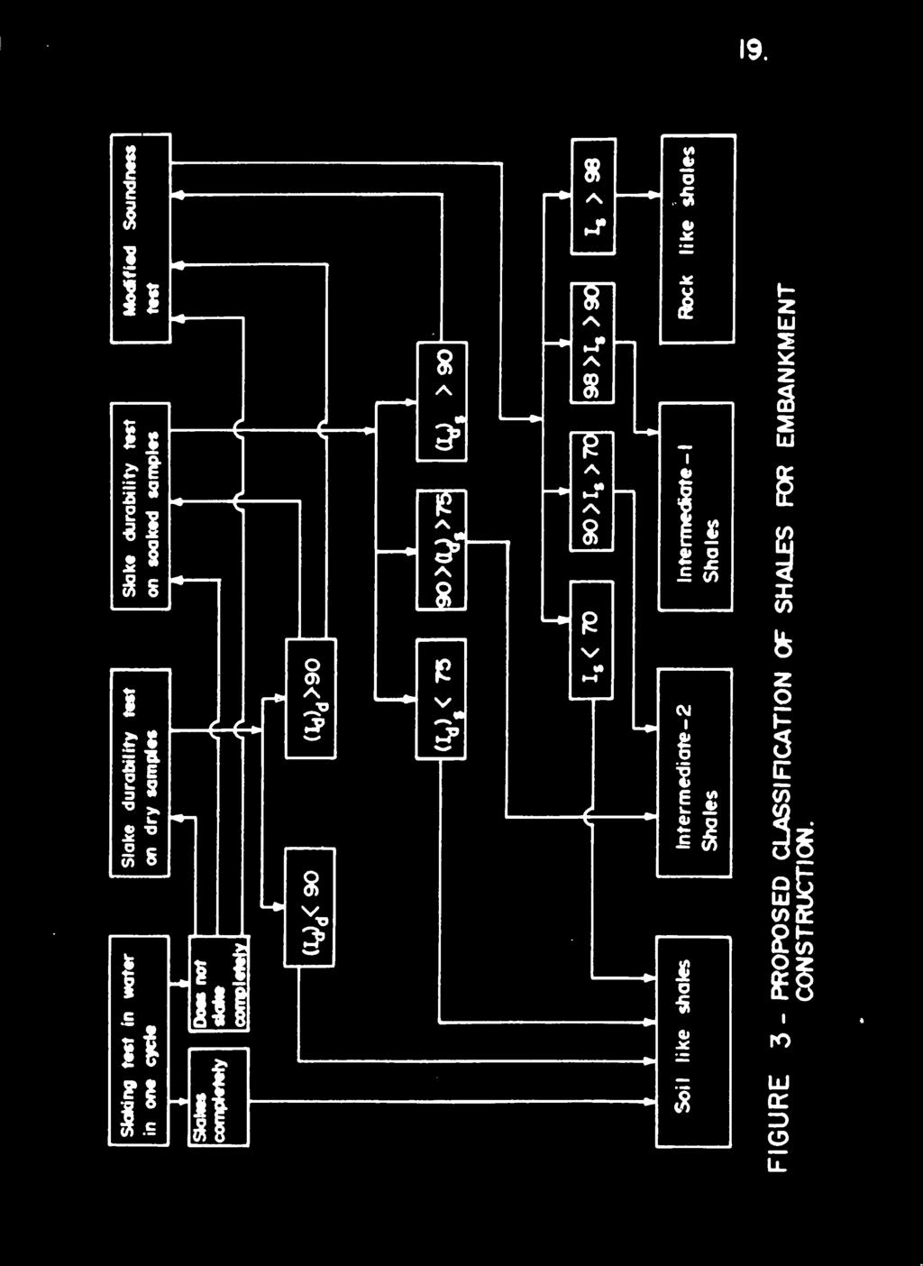
26 18. On the basis of A simple degradation type tests, shales can apparently be classified in the following four groups: 1. Rock like shales 2. lntermediate-1 shales 3. Intermediate-2 shales 4. Soil like shales The flow chart for classification is shown in Figure 3. RECOMMENDATIONS AND SUGGESTED CONSTRUCTION PRACTICES When shale is considered as a construction material in embankments in the midwestern U.S., it should be viewed as a special material, i.e., something between soil and rock. It should be classified in accordance with its probable behavior in the embankment. Before actually specifying use of this type of material, the following steps are recommended. 1. Review the design and construction standards and specifications which would apply if the embankments material were: (a) an average fine grained soil, or (b) an average sedimentary rock, i.e., consider the limits for the real material, which is generally intermediate. 2. Study the proposed fill material to determine whether it is grossly homogeneous or a mixture of unlike materials', e.g., shale and limestone. There are special hazards in the latter case, and extra special attention is required. 3. Perform the slake durability and modified soundness tests. Classify the material in one of the four groups suggested earlier, i.e., Rock like, lntermediate-1, Intermediate-2, or Soil like. (see Figure 3.)
27 19. </>
 1.")
28 20. For the different groups of shales, the following construction practices are suggested by the authors. (These opinions were derived intuitively on the basis of observations In the midwest, but without any actual field tests.) 1. If the material is Soil like, it should be thoroughly broken down before use, and thinner lifts than normally specified for soil may be needed. Expansive characteristics for the shale should also be determined. (Axial swell in the CBR test is a good descriptor. If the shale powder shows more swelling than that of ordinary clays, it should be accorded the special treatment given an expansive soil embankment, including an effective encasement of non-shale material. 2. For Intermediate-1 and Intermediate -2 shales, specifications should generally vary between those for soil and those for rock fills. Bigger chunks can be used. In Intermediate- 2 shales, it is probably necessary to have better density control and to employ an encasement. 3. A mixture of durable and non-durable material should not be used in an embankment, e.g., never mix a Rock like with Intermediate-2. The two materials will degrade quite differently in service, causing potentially major problems. Only top quality Intermediate-1 or Rock like shales should be mixed with limestone or sandstone. k. If it is not possible to separate good and bad shales, then the whole material should be treated like soil, i.e., be thoroughly broken down. ACKNOWLEDGMENTS Funding for this research was in part by the Purdue University Research Foundation, and in part by the Indiana State Highway Commission, through the Joint Highway Research Project. Personnel of the Division

29 21. of Materials and Tests, ISHC, were quite helpful in the progress of the vork.

30 22. BIBLIOGRAPHY Ackenheil, A. C., "Building Foundations on Appalachian Shales," presented at Engineering in Appalachian Shales Conference, West Virginia University, Morgantown, June American Association of State Highway Officials, Standard Specifications for Highway Materials and Methods of Sampling and Testing, Part II, 1966, Washington, D.C., 693 pp. American Society for Testing and Materials, Annual Book of ASTM Standards, Part 10, "Coi "Concrete and Mineral Aggregates ^ 1968, pp , 86-88, Deo, Purushottam, "Shales as Embankment Materials", Ph. D. Thesis, Purdue University, Dec. 1972, 202 pp. 5. Franklin, J. A., Broch, E., and Walton, G., "Logging the Mechanical Character of Rock," Rock Mechanics Research Report D-14, Imperial College, London, Gamble, J. C., "Durability-Plasticity Classification of Shales and Other Argillaceous Rocks," Ph.D. Thesis, University of Illinois at Urbana-Champaign, 1971, 161 pp. 7. Indiana State Highway Commission, Standard Specifications, 1971, Section 203, "Excavation and Embankment," pp Indiana State Highway Commission "Report on Failure of 1-74 Embankment in Southeastern Indiana," 1972, (draft only). 9. Ingram, R. L., "Fissility of Mudrocks," Bulletin of Geological Society of America, Vol. 64, Aug. 1953, pp Pettijohn, F. J., Sedimentary Rocks, Harper and Brothers, New York, 1957, 718 pp. 11. Philbrick, S. S., "Foundation Problems of Sedimentary Rocks," Applied Sedimentation, Chapter 8, P. D. Trask, pp Sherard, J. L., Woodward, R. J., Gizienski, S. F. and Clevenger, W. A., Earth and Earth Rock Dams, John Wiley and Sons, Inc., New York, 1963, 724 pp. 13. Soil Conservation Service, "Twin Rush Creek Test Fill Project," Washington County, U.S. Department of Agriculture, Indianapolis, Indiana, Twenhofel, W. H., "Terminology of the Fine-Grained Mechanical Sediments," Report of the Committee on Sedimentation, , National Research Council, pp Underwood, L. B., "Classification and Identification of Shales," Journal of the Soil Mechanics and Foundation Division, ASCE, Vol. 93, No. SM6, Nov. 1967, pp Vg2Jl 8» k * B «*HJRhway Engineering Handbook, McGraw-Hill, New York,

31 . 23. APPENDIX A TEST PROCEDURES Test for Slaking in Water in One Cycle of Wetting and Drying A broken piece of shale, roughly equi dimensional in shape and weighing between 50 and 60 gm, was oven dried at a temperature between 105 and 110 C for at least 8 hours. The shale piece was allowed to cool for 30 minutes at room temperature, followed by immersion so that it was at least 1/2 in. below the water surface. After immersion, the shale piece was observed continuously during the first hour; after that, the condition of the piece was checked at two, four, eight, twelve, and twenty-four hours. The condition of the piece was recorded as: "complete breakdown", "partial breakdown", or "no change". If the piece seemed intact, the cloudiness of the water was also noted. For any shale which slaked completely or partially, the test was repeated to verify the first result. Figures 1+ and 5 show the extremes of material response in the test. Test for Slaking in Water with Five Cycles of Wetting and Drying This test was first suggested by Philbrick (ll) to separate "compaction" and "cemented" shales A roughly equidimensional broken piece of shale weighing between 50 and 60 gm was oven dried at a temperature between 105 and 110 C for at least 8 hours. After cooling for 30 minutes at


32 FIGURE 4. CANNELTON SHALE AFTER 15 MINUTES OF IMMERSION IN WATER. 2U.

33 FIGURE 5. FttOLI 3 SHALE AFTER 24 HOURS OF IMMERSION IN WATER. 25.


34 . 26. room temperature, the piece was immersed at least 1/2 in. below the water level. After 16 hours, the shale piece was removed from the water, drained for 10 minutes, and dried at between 105 and 110 C for 8 hours. Five cycles of wetting and drying were repeated, and the condition of the sample was observed at the end of each cycle, and at the conclusion of the test. Slake Durability Test The slaking tests discussed above produce rather qualitative results. The slake durability test, on the other hand, measures a weight loss in water which can be expressed as a durability number (N, ). The durability number values vary not only with the type of shale, but, unfortunately, also with such test details as the initial moisture conditions of the shale charge and the testing time (drum revolutions). The apparatus was developed by Franklin and others at Imperial College London in 1970 (5). The test procedure was further developed and modified to suit Indiana shales. The apparatus, shown in Figure 6. consists of a drum of 2 mm mesh, 10 cm in length and ik cm in diameter. Both ends of the cylinder are solid and incorporate suitable driving dogs. One side plate has a quick release mechanism, to permit easy placement and removal of the shale samples A motor drive unit attached to the drum revolves it at a speed of 20 rpm in a water trough. The test drum is supported on water lubricated 1. Weight-slaked measurements are possible, but not usual.

35 FIGURE 6. SLAKE DURABILITY APR&RATUS 27.

36 . 28. bearings, allowing h cm unobstructed clearance below the drum. The trough water level is 2 cm below the axis of the drum. A sample of ten representative shale pieces, each weighing 50 to 60 gm, was oven dried and placed in the test drum. The drum was rotated, and material detached from the pieces passed through the mesh, i.e., became a sample weight loss. The durability number (N,) was calculated as the percentage ratio of final to initial dry sample weights, N, =?~ 100 where d A-C N = Durability number for a shale for a given number of drum revolutions and given initial condition of shale (oven-dried or soaked) A = Weight of drum plus dry sample before test. B = Weight of drum plus dry sample retained after test. C = Weight of clean and dry drum. As suggested above, the test was conducted not only on oven-dried samples, but also on samples which were immersed in water (soaked) for six hours before testing. Dry sample weights were used in all calculations. To determine a suitable value for the standard number of revolutions, preliminary tests were conducted on selected samples for 100, 200, 500 and 1000 revolutions of the drum. The weight loss through the meshed drum increases with the number of revolutions, except that at a higher number of revolutions, viz., 1000, the results were not always reproducible. Five hundred revolutions seems a
 d d» and for soaked samples, (I.), were determined.")
37 . 29. reasonable compromise, since it produced both a wide range of durability numbers among the shales and reproducible results for a given shale. The durability number for 500 revolutions was redefined as the durability index (ij. Durability indexes both for dry samples, d ) d d» and for soaked samples, (I.), were determined. At least two tests d s were run for each combination of variables. The values reported are averages. The lower I, values indicate a less durable shale. Soaked Q values (I,) were always lower than the dry ones (I,),, as d d Modified Soundness Test This test measures the degradation of shales when subjected to five cycles of alternate wetting and drying in a sodium sulfate solution. It is more severe than the previously mentioned slaking tests, and is more effective in distinguishing among the harder and more durable shales The test was modified from ASTM C 88-63, Sodium Sulfate Soundness Test ( 3), which is used to determine the resistance of mineral aggregates to disintegration by a saturated sodium sulfate or magnesium sulfate solution. The standard test proved to be too severe for shales, and after a series of trials, the solution was reduced to 50$ saturation. The charge of shale fragments was 1000 gm, of which 330 gm was between 1/2 in. and 3/8 in., and 670 gm was between 3A in. and 1/2 in. Pieces in this size range were roughly equidimensional. Larger pieces tended to be plate shaped, due to the laminated nature of the rock.
 The sample was washed with water, and oven dried at 105 to 110 C before weighing.")
38 30. (Definition of size by a sieving process of course becomes more arbitrary as the pieces depart from a bulky shape.) The sample was washed with water, and oven dried at 105 to 110 C before weighing. A saturated solution of anhydrous granular sodium sulfate was prepared in accordance with ASTM C procedures (3). The solution was diluted to 50# saturation by adding an equal volume of water. The solution was prepared at least 2k hours in advance of the start of test. The sample was immersed in the sodium sulfate solution for not less than 16 hours and not more than 18 hours. The solution covered the shale chunks to a depth of at least 1/2 in. The immersion was conducted at a room temperature of F. The sample was removed from the solution, drained for 15 minutes, placed in the drying oven at 105 to 110 C, and dried to constant weight. After the sample had cooled to room temperature, the process was repeated. Upon completion of five cycles of immersion and drying, the sample was washed with water until free of sodium sulfate, as determined by the reaction of the wash water with barium chloride (BaCl? ). It was then dried and fractioned on a 5/16 in. sieve. The weight retained on the sieve was determined. Each test was repeated at least once, and average values were reported. The Soundness Index, I, was defined as the percent retained by s weight on the 5/l6 in. sieve. Durability is considered to increase with an increase in the value of I. s
 Standard effort: 5-5 lb rammer with 12 in. fall, 3 layers, 56 uniformly distributed blows per layer; ii) 0.5 Standard effort: same as above, but 38 uniformly distributed blows per layer; iii) 1.")
39 ) 31. Compaction and Load-Deformation Tests These tests were conducted in 6 in. diameter CBR molds. The tests were performed at the k compaction effort levels listed below. i) Standard effort: 5-5 lb rammer with 12 in. fall, 3 layers, 56 uniformly distributed blows per layer; ii) 0.5 Standard effort: same as above, but 38 uniformly distributed blows per layer; iii) 1.8 Standard effort: same as above, but 100 uniformly distributed blows per layer; iv) U.5 Standard effort: 10 lb. rammer with 18 in. fall, 5 layers, 56 uniformly distributed blows per layer. For every test the following information was obtained: a) Compaction effort, b) Molding water content, c) Dry density as compacted, d) Swell, e) CBR as compacted, f CBR soaked, g) Ratio of CBR soaked and CBR as compacted. Breaking Characteristics Test The breaking characteristics may be the most descriptive feature for shales. They can be thus classified as massive, flaky-fissile and flaggy-fissile. Fissility is associated with a parallel arrangement of particulate units and non-fissility with a random arrangement (9). The


40 32. nature of cementing agents is also an important factor that influences fissility. Massive rocks have no preferred directions of cleaving and breaking, and most of the fragments are blocky. Flaggy rocks will split into fragments of varying thickness, but have a width and length many times greater than the thickness, and with two essentially flat sides approximately parallel. Flaky shales split along irregular surfaces parallel to the bedding and into uneven flakes, thin chips, and wedgelike fragments whose length seldom exceeds three inches. The three breaking types are shown in Figures J, 8 and 9. Shales and other soft rocks actually combine varying amounts of massiveness, flagginess and flakiness, which can be represented by points on a triangular diagram. Shales were broken by a hammer, with a large area of contact, or by striking two pieces of shale together. About 1,000 gm of shale were broken in this way, applying approximately the same breaking effort to each batch of shale. Shale pieces with massive, flaggy and flaky characteristics were separated and weighed. Proportions of the three different breaking types were determined to the nearest 10 percent by weight 1. Much in the same manner as for a soil texture diagram for sand, silt and clay sizes.


41 FIGURE 7. MASSIVE BREAKING TYPE. 33.

42 FIGURE 8. FLAGGY BREAKING TYPE. 3k.
43 FIGURE 9. FLAKY BREAKING TYPE. 35.

44

45
TESTING of AGGREGATES for CONCRETE
 TESTING of AGGREGATES for CONCRETE The properties of the aggregates affect both the fresh and hardened properties of concrete. It is crucial to know the properties of the aggregates to be used in the making
Geology 229 Engineering Geology. Lecture 7. Rocks and Concrete as Engineering Material (West, Ch. 6)
") Geology 229 Engineering Geology Lecture 7 Rocks and Concrete as Engineering Material (West, Ch. 6) Outline of this Lecture 1. Rock mass properties Weakness planes control rock mass strength; Rock textures;
Geology 229 Engineering Geology Lecture 7 Rocks and Concrete as Engineering Material (West, Ch. 6) Outline of this Lecture 1. Rock mass properties Weakness planes control rock mass strength; Rock textures;
Introduction to Soil Mechanics Geotechnical Engineering-II
 Introduction to Soil Mechanics Geotechnical Engineering-II ground SIVA Dr. Attaullah Shah 1 Soil Formation Soil derives from Latin word Solum having same meanings as our modern world. From Geologist point
CHAPTER 15 ROCK SLAKE DURABILITY
 PENNSYLVANIA DEPARTMENT OF TRANSPORTATION PUBLICATION 293 2017 GEOTECHNICAL ENGINEERING MANUAL CHAPTER 15 ROCK SLAKE DURABILITY 2017-11-3 DRAFT 15-1 Contents 15.1 INTRODUCTION AND DESCRIPTION OF SLAKING...
Slake Durability of a Deep Red Stratum Sandstone under Different Environments
 An Interdisciplinary Response to Mine Water Challenges - Sui, Sun & Wang (eds) 2014 China University of Mining and Technology Press, Xuzhou, ISBN 978-7-5646-2437-8 Slake Durability of a Deep Red Stratum
Rock Material. Chapter 3 ROCK MATERIAL HOMOGENEITY AND INHOMOGENEITY CLASSIFICATION OF ROCK MATERIAL
 Chapter 3 Rock Material In all things of nature there is something of the marvelous. Aristotle ROCK MATERIAL The term rock material refers to the intact rock within the framework of discontinuities. In
Assistant Prof., Department of Civil Engineering Bhagwant University,Ajmer,Rajasthan,India ABSTRACT
 Study of Index Properties of the Soil 1 Mr Utkarsh Mathur 2 Mr Nitin Kumar 3 Mr Trimurti Narayan Pandey 4 Mr.Amit Choudhary 1 PG Scholar, Department of Civil Engineering Bhagwant University,Ajmer,Rajasthan,India
Soil Mechanics. Chapter # 1. Prepared By Mr. Ashok Kumar Lecturer in Civil Engineering Gpes Meham Rohtak INTRODUCTION TO SOIL MECHANICS AND ITS TYPES
 Soil Mechanics Chapter # 1 INTRODUCTION TO SOIL MECHANICS AND ITS TYPES Prepared By Mr. Ashok Kumar Lecturer in Civil Engineering Gpes Meham Rohtak Chapter Outlines Introduction to Soil Mechanics, Soil
GeoShanghai 2010 International Conference Paving Materials and Pavement Analysis
 Particle Shape, Type and Amount of Fines, and Moisture Affecting Resilient Modulus Behavior of Unbound Aggregates Debakanta Mishra 1, Erol Tutumluer 2, M. ASCE, Yuanjie Xiao 3 1 Graduate Research Assistant,
Chapter 2. The Ideal Aggregate. Aggregates
 Chapter 2 Aggregates The Ideal Aggregate Strong and resists loads applied Chemically inert so it is not broken down by reactions with substances it comes in contact with Has a stable volume so that it
Schedule of Accreditation issued by United Kingdom Accreditation Service 2 Pine Trees, Chertsey Lane, Staines-upon-Thames, TW18 3HR, UK
 Unit 4 Heol Aur Dafen Industrial Estate Dafen Carmarthenshire SA14 8QN Contact: Mr P Evans Tel: +44 (0)1554 784040 Fax: +44 (0)1554 784041 E-Mail: pevans@gstl.co.uk Website: www.gstl.co.uk locations: Testing
EVALUATION OF VACUUM DRYING FOR DETERMINATION OF BULK SPECIFIC GRAVITY OF HMA SAMPLES
 Cross and Pokhrel 1 EVALUATION OF VACUUM DRYING FOR DETERMINATION OF BULK SPECIFIC GRAVITY OF HMA SAMPLES 6784 Equivalent Words by: Stephen A. Cross, Ph.D., P.E. Professor School of Civil and Environmental
Geology 229 Engineering Geology. Lecture 6. Basic Rock Classification and Engineering Considerations (West, Chs. 2, 3, 4, 5)
") Geology 229 Engineering Geology Lecture 6 Basic Rock Classification and Engineering Considerations (West, Chs. 2, 3, 4, 5) Outline of this Lecture 1. Rock types and rock cycle 2. Geological and engineering
Geology 229 Engineering Geology Lecture 6 Basic Rock Classification and Engineering Considerations (West, Chs. 2, 3, 4, 5) Outline of this Lecture 1. Rock types and rock cycle 2. Geological and engineering
Asphalt Mix Designer. Module 2 Physical Properties of Aggregate. Specification Year: July Release 4, July
 Specification Year: July 2005 Release 4, July 2005 2-1 The first step in the development of an HMA mix design is to identify the materials that will be used in the pavement. In Florida the asphalt binder
 SOIL CLASSIFICATION CHART COARSE-GRAINED SOILS MORE THAN 50% RETAINED ON NO.200 SIEVE FINE-GRAINED SOILS 50% OR MORE PASSES THE NO.200 SIEVE PRIMARY DIVISIONS GRAVELS MORE THAN 50% OF COARSE FRACTION RETAINED
Large chunks. voids. Use of Shale in Highway Embankments
 Use of Shale in Highway Embankments C. W. Lovell R esearch Engineer Joint Highway R esearch Project School of Civil E ngineering P urdue University IN T R O D U C T IO N Poor perform ance of m idw estern
Aggregates for Concrete
 Fine Aggregate Sand and/or crushed stone < 5 mm (0.2 in.) F.A. content usually 35% to 45% by mass or volume of total aggregate Coarse Aggregate Gravel and crushed stone 5 mm (0.2 in.) typically between
Lessons Learned from the Performance of a Degradable Shale Embankment: Case Study
 Missouri University of Science and Technology Scholars' Mine International Conference on Case Histories in Geotechnical Engineering (2008) - Sixth International Conference on Case Histories in Geotechnical
Basic Aggregates Study Guide
 Basic Aggregates Study Guide General Conversions 1) There are pounds in one ton. 2) There are grams in one pound. 3) One kilogram consists of grams. 4) The linear distance that one station covers is feet.
Correlation of unified and AASHTO soil classification systems for soils classification
 Journal of Earth Sciences and Geotechnical Engineering, vol. 8, no. 1, 2018, 39-50 ISSN: 1792-9040 (print version), 1792-9660 (online) Scienpress Ltd, 2018 Correlation of unified and AASHTO classification
Geotechnical Engineering I CE 341
 Geotechnical Engineering I CE 341 What do we learn in this course? Introduction to Geotechnical Engineering (1) Formation, Soil Composition, Type and Identification of Soils (2) Soil Structure and Fabric
Clay Robinson, PhD, CPSS, PG copyright 2009
 Engineering: What's soil got to do with it? Clay Robinson, PhD, CPSS, PG crobinson@wtamu.edu, http://www.wtamu.edu/~crobinson, copyright 2009 Merriam-Webster Online Dictionary soil, noun 1 : firm land
Geology 229 Engineering and Environmental Geology. Lecture 5. Engineering Properties of Rocks (West, Ch. 6)
") Geology 229 Engineering and Environmental Geology Lecture 5 Engineering Properties of Rocks (West, Ch. 6) Outline of this Lecture 1. Triaxial rock mechanics test Mohr circle Combination of Coulomb shear
Geology 229 Engineering and Environmental Geology Lecture 5 Engineering Properties of Rocks (West, Ch. 6) Outline of this Lecture 1. Triaxial rock mechanics test Mohr circle Combination of Coulomb shear
SECTION AGGREGATE OR GRANULAR SUBBASE
 SECTION 02230 AGGREGATE OR GRANULAR SUBBASE PART 1 GENERAL 1.01 SECTION INCLUDES A. Aggregate or granular subbase as shown on the drawings. 1.02 RELATED SECTIONS A. Section 01400 Quality Requirements.
Boreholes. Implementation. Boring. Boreholes may be excavated by one of these methods: 1. Auger Boring 2. Wash Boring 3.
 Implementation Boreholes 1. Auger Boring 2. Wash Boring 3. Rotary Drilling Boring Boreholes may be excavated by one of these methods: 4. Percussion Drilling The right choice of method depends on: Ground
Mechanistic Investigation of Granular Base and Subbase Materials A Saskatchewan Case Study
 Mechanistic Investigation of Granular Base and Subbase Materials A Saskatchewan Case Study Curtis Berthelot, P. Eng. Department of Civil and Geological Engineering University of Saskatchewan 57 Campus
Soil Mechanics Brief Review. Presented by: Gary L. Seider, P.E.
 Soil Mechanics Brief Review Presented by: Gary L. Seider, P.E. 1 BASIC ROCK TYPES Igneous Rock (e.g. granite, basalt) Rock formed in place by cooling from magma Generally very stiff/strong and often abrasive
NHBRA SOIL LABORATORY SECTION INTERIM REVISED TEST RATES FOR THE MATERIALS LABORATORY
 NHBRA SOIL LABORATORY SECTION INTERIM REVISED TEST RATES FOR THE MATERIALS LABORATORY DATE OF REVISION: ) 10th October 2010 S/N TEST DESCRIPTION UNIT RATE REMARKS 1 Sieve Analysis (wet and dry methods
Characterization of Sand Formation from a Crude Oilfield
 This work by IJARBEST is licensed under Creative Commons Attribution 4.0 International License. Available at https://www.ijarbest.com Characterization of Sand Formation from a Crude Oilfield 1 A. Sivasakthi,
2 Aggregates in Indiana
 2 Aggregates in Indiana Origin of Aggregates Gravel and Natural Sands Crushed Stone Slag Distribution of Aggregates Glacial Deposits Bedrock Deposits Aggregate Types Natural Aggregates Artificial Aggregates
Chapter I Basic Characteristics of Soils
 Chapter I Basic Characteristics of Soils Outline 1. The Nature of Soils (section 1.1 Craig) 2. Soil Texture (section 1.1 Craig) 3. Grain Size and Grain Size Distribution (section 1.2 Craig) 4. Particle
J. Paul Guyer, P.E., R.A.
 J. Paul Guyer, P.E., R.A. Paul Guyer is a registered mechanical engineer, civil engineer, fire protection engineer and architect with over 35 years experience in the design of buildings and related infrastructure.
PHYSICO-MECHANICAL PROPERTIES OF ROCKS LECTURE 2. Contents
 PHYSICO-MECHANICAL PROPERTIES OF ROCKS LECTURE 2 Contents 2.1 Introduction 2.2 Rock coring and logging 2.3 Physico-mechanical properties 2.3.1 Physical Properties 2.3.1.1 Density, unit weight and specific
REPORT ON THE ASSESSMENT OF TRENCHING INTHE ROAD RESERVE OF THE ROAD BETWEEN BEAUFORT WEST AND CARNAVON.
 Contract Report CSIR/BE/TIE/SKA/59E2214 August 2018 REPORT ON THE ASSESSMENT OF TRENCHING INTHE ROAD RESERVE OF THE ROAD BETWEEN BEAUFORT WEST AND CARNAVON. Authors: Dave Ventura Anele Sambo Michael Roux
ARCH 1250 APPLIED ENVIRONMENTAL STUDIES
 John Seitz, RA, LEED AP Assistant Adjunct Professor Professor Paul C. King, RA, AIA, ARA Assistant Professor Geology Geology is the scientific study of the structure and composition of the earth s surface
LAB 2 IDENTIFYING MATERIALS FOR MAKING SOILS: ROCK AND PARENT MATERIALS
 LAB 2 IDENTIFYING MATERIALS FOR MAKING SOILS: ROCK AND PARENT MATERIALS Learning outcomes The student is able to: 1. understand and identify rocks 2. understand and identify parent materials 3. recognize
DESIGN OF ULTRA-THIN BONDED HOT MIX WEARING COURSE (UTBHMWC) MIXTURES
 MIXTURES") Test Procedure for DESIGN OF ULTRA-THIN BONDED HOT MIX WEARING COURSE TxDOT Designation: Tex-247-F Effective Date: August 2008 August 2016. 1. SCOPE 1.1 This test method determines the proper proportions
Test Procedure for DESIGN OF ULTRA-THIN BONDED HOT MIX WEARING COURSE TxDOT Designation: Tex-247-F Effective Date: August 2008 August 2016. 1. SCOPE 1.1 This test method determines the proper proportions
Stone Outlet Sediment Trap
 3.12 Sediment Control Description: A stone outlet sediment trap is a small detention area formed by placing a stone embankment with an integral stone filter outlet across a drainage swale for the purpose
The Use of the Crumb Test as a Preliminary Indicator of Dispersive Soils
 Proceedings of the 15th African Regional Conference on Soil Mechanics and Geotechnical Engineering C. Quadros and S.W. Jacobsz (Eds.) IOS Press, 2011 2011 The authors and IOS Press. All rights reserved.
4. Soil Consistency (Plasticity) (Das, chapter 4)
 (Das, chapter 4)") 4. Soil Consistency (Plasticity) (Das, chapter 4) 1 What is Consistency? Consistency is a term used to describe the degree of firmness of fine-grained soils (silt and clay). The consistency of fine grained
4. Soil Consistency (Plasticity) (Das, chapter 4) 1 What is Consistency? Consistency is a term used to describe the degree of firmness of fine-grained soils (silt and clay). The consistency of fine grained
Wikipedia.org BUILDING STONES. Chapter 4. Materials of Construction-Building Stones 1
 Wikipedia.org BUILDING STONES Chapter 4 Materials of Construction-Building Stones 1 What is Stone? Stone is a concretion of mineral matter. Used either as a; Construction material, Manufacture of other
UNIT 4 SEDIMENTARY ROCKS
 UNIT 4 SEDIMENTARY ROCKS WHAT ARE SEDIMENTS Sediments are loose Earth materials (unconsolidated materials) such as sand which are transported by the action of water, wind, glacial ice and gravity. These
Engineering materials
 1 Engineering materials Lecture 9 Aggregates 2 Composition and structure Natural aggregates are derived from rocks. Classification: Igneous( 火成岩 ), sedimentary ( 沉積岩 ) and metamorphic ( 變質岩 ) Fine or coarse
The Use of Expanded Shale, Clay and Slate Lightweight Aggregates in Granular Geotechnical Fills
 Information Sheet 6660.0 January 2017 The Use of Expanded Shale, Clay and Slate Lightweight Aggregates in Granular Geotechnical Fills For over 50 years Rotary Kiln produced Expanded Shale, Clay & Slate
A LABORATORY AND FIELD STUDY OF COBBLE ABRASION
 A LABORATORY AND FIELD STUDY OF COBBLE ABRASION Preliminary Report University of Chicago INTRODUCTION AND OBJECT In the course of field work at Baraboo, Wisconsin, in the summer of 1916, it occurred to
Chapter 1 - Soil Mechanics Review Part A
 Chapter 1 - Soil Mechanics Review Part A 1.1 Introduction Geotechnical Engineer is concerned with predicting / controlling Failure/Stability Deformations Influence of water (Seepage etc.) Soil behavour
Engineering Properties of Soil-Fly Ash Subgrade Mixtures
 Engineering Properties of Soil-Fly Ash Subgrade Mixtures Zachary G. Thomas Graduate Research Assistant Iowa State University Department of Civil and Construction Engineering 394 Town Engineering Building
12 th ICSGE Dec Cairo - Egypt
 12 th ICSGE 10-12 Dec. 2007 Cairo - Egypt Ain Shams University Faculty of Engineering Department of Structural Engineering Twelfth International Colloquium on Structural and Geotechnical Engineering CORRELATIONS
Tikrit University College of Engineering Civil engineering Department
 Tikrit University SOIL CLASSIFICATION College of Engineering Civil engineering Department Soil Mechanics 3 rd Class Lecture notes Up Copyrights 2016 Classification of soil is the separation of soil into
Ecoregions Glossary. 7.8B: Changes To Texas Land Earth and Space
 Ecoregions Glossary Ecoregions The term ecoregions was developed by combining the terms ecology and region. Ecology is the study of the interrelationship of organisms and their environments. The term,
CE 240 Soil Mechanics & Foundations Lecture 5.2. Permeability III (Das, Ch. 6) Summary Soil Index Properties (Das, Ch. 2-6)
 Summary Soil Index Properties (Das, Ch. 2-6)") CE 40 Soil Mechanics & Foundations Lecture 5. Permeability III (Das, Ch. 6) Summary Soil Index Properties (Das, Ch. -6) Outline of this Lecture 1. Getting the in situ hydraulic conductivity 1.1 pumping
CE 40 Soil Mechanics & Foundations Lecture 5. Permeability III (Das, Ch. 6) Summary Soil Index Properties (Das, Ch. -6) Outline of this Lecture 1. Getting the in situ hydraulic conductivity 1.1 pumping
SOIL AND AGGREGATE FUNDAMENTALS STUDENT GUIDE AMRC April, 2006 AREA MANAGER ROADS CERTIFICATION PROGRAM FOR EDUCATIONAL PURPOSES ONLY
 AREA MANAGER ROADS CERTIFICATION PROGRAM AMRC 2011 SOIL AND AGGREGATE FUNDAMENTALS STUDENT GUIDE FOR EDUCATIONAL PURPOSES ONLY April, 2006 WPC #28013 07/09 2009 by British Columbia Institute of Technology
Chapter 6 Sedimentary and Metamorphic Rock
 Chapter 6 Sedimentary and Metamorphic Rock Weathering and Erosion Wherever rock is exposed at Earth s surface, it is continuously being broken down by weathering a set of physical and chemical processes
Eight Years of Pulse Velocity Tests on Concrete Pavements in Kansas
 Eight Years of Pulse Velocity Tests on Concrete Pavements in Kansas RICHARD C. MEYER, Electronics Engineer, State Highway Commission of Xansas For the past eight years the Kansas Highway Commission has
Module 1 GEOTECHNICAL PROPERTIES OF SOIL AND OF REINFORCED SOIL (Lectures 1 to 4)
") Module 1 GEOTECHNICAL PROPERTIES OF SOIL AND OF REINFORCED SOIL (Lectures 1 to 4) Topics 1.1 INTRODUCTION 1.2 GRAIN-SIZE DISTRIBUTION Sieve Analysis Hydrometer Analysis 1.3 SIZE LIMITS FOR SOILS 1.4 WEIGHT-VOLUME
Module 1 GEOTECHNICAL PROPERTIES OF SOIL AND OF REINFORCED SOIL (Lectures 1 to 4) Topics 1.1 INTRODUCTION 1.2 GRAIN-SIZE DISTRIBUTION Sieve Analysis Hydrometer Analysis 1.3 SIZE LIMITS FOR SOILS 1.4 WEIGHT-VOLUME
ROCK EXCAVATION (GRADING) OPSS 206 INDEX
 OPSS 206 INDEX") 206-2 - OPSS 206 INDEX 206-2.1 GENERAL 206-2.1.1 Classification of Rock Materials 206-2.1.2 Tender Items 206-2.1.3 Other Excavation Tender Items 206-2.1.4 Specifications 206-2.1.5 Special Provisions 206-2.1.6
206-2 - OPSS 206 INDEX 206-2.1 GENERAL 206-2.1.1 Classification of Rock Materials 206-2.1.2 Tender Items 206-2.1.3 Other Excavation Tender Items 206-2.1.4 Specifications 206-2.1.5 Special Provisions 206-2.1.6
Chapter (12) Instructor : Dr. Jehad Hamad
 Instructor : Dr. Jehad Hamad") Chapter (12) Instructor : Dr. Jehad Hamad 2017-2016 Chapter Outlines Shear strength in soils Direct shear test Unconfined Compression Test Tri-axial Test Shear Strength The strength of a material is the
Chapter (12) Instructor : Dr. Jehad Hamad 2017-2016 Chapter Outlines Shear strength in soils Direct shear test Unconfined Compression Test Tri-axial Test Shear Strength The strength of a material is the
Mechanical Weathering
 Weathering is the disintegration and decomposition of material at or near the surface. Erosion is the incorporation and transportation of material by a mobile agent, usually water, wind, or ice. Geologists
NOTES ON SUBBASE AGGREGATE SPECIFICATION TNZ M/3. These notes must not be included in the Contract Documents.
 TNZ M/3 Notes : 1986 NOTES ON SUBBASE AGGREGATE SPECIFICATION TNZ M/3 These notes must not be included in the Contract Documents. 1. INTRODUCTION There is no standard TNZ M/3 Specification for subbase
The more common classification systems are enlisted below:
 A number of systems of classification have been evolved for categorizing various types of soil. Some of these have been developed specifically in connection with ascertaining the suitability of soil for
Effect of Lime on the Compressibility Characteristics of a Highly Plastic Clay
 Effect of Lime on the Compressibility Characteristics of a Highly Plastic Clay Abstract İnci Süt-Ünver Ph.D. Candidate Istanbul Technical University Istanbul - Turkey Musaffa Ayşen Lav Prof. Dr. Istanbul
SPECIFIC GRAVITY AND ABSORPTION OF COARSE AGGREGATE FOP FOR AASHTO T 85
 SPECIFIC GRAVITY AND ABSORPTION OF COARSE AGGREGATE FOP FOR AASHTO T 85 Scope This procedure covers the determination of specific gravity and absorption of coarse aggregate in accordance with AASHTO T
Geology 229 Engineering Geology. Lecture 8. Elementary Soil Mechanics (West, Ch. 7)
") Geology 229 Engineering Geology Lecture 8 Elementary Soil Mechanics (West, Ch. 7) Outline of this Lecture 1. Introduction of soil properties 2. Index properties of soils Soil particles Phase relationship
Geology 229 Engineering Geology Lecture 8 Elementary Soil Mechanics (West, Ch. 7) Outline of this Lecture 1. Introduction of soil properties 2. Index properties of soils Soil particles Phase relationship
SST3005 Fundamentals of Soil Science LAB 5 LABORATORY DETERMINATION OF SOIL TEXTURE: MECHANICAL ANALYSIS
 LAB 5 LABORATORY DETERMINATION OF SOIL TEXTURE: MECHANICAL ANALYSIS Learning outcomes The student is able to: 1. Separate soil particles : sand, silt and clay 2. determine the soil texture class using
CE330L Student Lab Manual Mineral Aggregate Properties
 Mineral Aggregate Properties Introduction In this lab module several characteristics of aggregates are determined. Tests will be conducted on both coarse and fine aggregates. The results of some of these
SLOPE STABILITY EVALUATION AND ACCEPTANCE STANDARDS
 INFORMATION BULLETIN / PUBLIC - BUILDING CODE REFERENCE NO.: LAMC 98.0508 Effective: 1-26-84 DOCUMENT NO. P/BC 2002-049 Revised: 11-1-02 Previously Issued As: RGA #1-84 SLOPE STABILITY EVALUATION AND ACCEPTANCE
Chapter 6 Bearing Capacity
 Chapter 6 Bearing Capacity 6-1. Scope This chapter provides guidance for the determination of the ultimate and allowable bearing stress values for foundations on rock. The chapter is subdivided into four
SOIL MECHANICS SAB1713 DR. HETTY
 SOIL MECHANICS SAB1713 DR. HETTY INTRODUCTION SOIL MECHANICS -Concerned solely with soils -Concerned with the deformation and strength of bodies of soils -Concerned with the interaction of structures with
Durability Assessment of Weak Rock by Using Jar Slaking Test
 Durability Assessment of Weak Rock by Using Jar Slaking Test Edy Tonnizam Mohamad Senior Lecturer, Faculty of Civil Engineering, Universiti Teknologi Malaysia edy@utm.my Rosli Saad School of Physics, Universiti
Prof. B V S Viswanadham, Department of Civil Engineering, IIT Bombay
 06 Index properties Review Clay particle-water interaction Identification of clay minerals Sedimentation analysis Hydrometer analysis 0.995 20-40 Hydrometer is a device which is used to measure the specific
SPECIFIC GRAVITY AND ABSORPTION OF COARSE AGGREGATE FOP FOR AASHTO T 85
 SPECIFIC GRAVITY AND ABSORPTION OF COARSE AGGREGATE FOP FOR AASHTO T 85 Scope This procedure covers the determination of specific gravity and absorption of coarse aggregate in accordance with AASHTO T
This Specification is for the supply of sands, crushed rock and crushed scoria to Melbourne Water work sites.
 Melbourne Water SANDS, CRUSHED ROCK AND CRUSHED SCORIA SPECIFICATION 21.A.038 1 GENERAL This Specification is for the supply of sands, crushed rock and crushed scoria to Melbourne Water work sites. 2 SOURCES
Stabilisation of Soil Using Sodium Hydroxide Additive
 Stabilisation of Soil Using Sodium Hydroxide Additive 1 Krishna Keshav, M. Tech Student, Civil Engineering Department, BIT Sindri, Dhanbad, India 2 M.K. Mishra, Assistant Professor, Department of Chemistry,
Aggregates. AAPA training
 Aggregates AAPA training Topics Aggregate sources and rock types Aggregate Production Aggregate Properties Coarse and fine aggregates in Asphalt Mixes Aggregates in Sprayed Seals Filler in asphalt mixes
Mar 1, 2018 LAB MANUAL INDEX 1. Table of Contents Laboratory Testing Methods Reducing Aggregate Field Samples to Testing Size (Ver.
 Mar 1, 2018 LAB MANUAL INDEX 1 Table of Contents Laboratory Testing Methods 1000 Standard Practices (Ver. Sep 23, 2014) 1001 Receiving and Identifying Samples (Ver. Mar 1, 2018) 1002 Reducing Aggregate
ROCK TUMBLING: An Experimental Investigation of Physical Weathering
 EESC 7040: Geology through Global Arts and Artifacts ROCK TUMBLING: An Experimental Investigation of Physical tumblers create smooth, polished stones by physically weathering rocks within the tumbler s
Analysis of Clays and Soils by XRD
 Analysis of Clays and Soils by XRD I. Introduction Proper sample preparation is one of the most important requirements in the analysis of powder samples by X-ray diffraction (XRD). This statement is especially
Sedimentary Rocks. All sedimentary rocks begin to form when existing rocks are broken down into sediments Sediments are mainly weathered debris
 Rocks! Objectives Describe the major processes involved in the formation of sedimentary rock Distinguish between clastic sedimentary rocks and chemical sedimentary rocks Identify the features that are
SILT FENCE EFFECTIVENESS
 SILT FENCE EFFECTIVENESS Michelle G. Holloway, Department of Earth Sciences, University of South Alabama, Mobile, AL 36688. E-mail: MLG@jaguar1.usouthal.edu. Sediment is the number one pollutant in Dog
LANDSLIDES IN THE WHITE MOUNTAIN (GEOTECHNICAL STUDIES AND ENGINEERING TESTS)
") J. Al Azhar University Gaza 2004, Vol. 7, NO. 2 P 15-26 LANDSLIDES IN THE WHITE MOUNTAIN (GEOTECHNICAL STUDIES AND ENGINEERING TESTS) Isam G. Jardaneh (1), Jalal Al-Dabeek (2), Abdel hakeem Al-Jawhari
J. Al Azhar University Gaza 2004, Vol. 7, NO. 2 P 15-26 LANDSLIDES IN THE WHITE MOUNTAIN (GEOTECHNICAL STUDIES AND ENGINEERING TESTS) Isam G. Jardaneh (1), Jalal Al-Dabeek (2), Abdel hakeem Al-Jawhari
Evaluation of Resistance to Los Angeles Abrasion and Physical Factors with Grindability Properties of Some Aggregate Materials
 Int. J. Econ. Environ. Geol. Vol. 8 (1) 14-19, 2017 Sensogut and Cinar/Int.J.Econ.Environ.Geol.Vol. 8(1) 14-19, 2017 Journal home page: www.econ-environ-geol.org Open Access ISSN: 2223-957X 8 th International
CONCRETE IN THE MIDDLE EAST
 CONCRETE IN THE MIDDLE EAST ALKALI REACTIVITY IN CONCRETE STRUCTURES Presented by : Eng. ELIE J. SFEIR INTRODUCTION What is the Alkali-Reactivity? The alkali reaction is a chemical reaction between some
WACEL AGGREGATE LABORATORY TESTING TECHNICIAN
 STUDY GUIDE WACEL AGGREGATE LABORATORY TESTING TECHNICIAN August 2016 Study Guide Aggregate Laboratory Testing General: An aggregate laboratory technician shall have sufficient training, education, and
10. GEOTECHNICAL EXPLORATION PROGRAM
 Geotechnical site investigations should be conducted in multiple phases to obtain data for use during the planning and design of the tunnel system. Geotechnical investigations typically are performed in
Review - Unit 2 - Rocks and Minerals
 Review - Unit 2 - Rocks and Minerals Base your answers to questions 1 and 2 on the diagram below, which shows the results of three different physical tests, A, B, and C, that were performed on a mineral.
B-1 BORE LOCATION PLAN. EXHIBIT Drawn By: 115G BROOKS VETERINARY CLINIC CITY BASE LANDING AND GOLIAD ROAD SAN ANTONIO, TEXAS.
 N B-1 SYMBOLS: Exploratory Boring Location Project Mngr: BORE LOCATION PLAN Project No. GK EXHIBIT Drawn By: 115G1063.02 GK Scale: Checked By: 1045 Central Parkway North, Suite 103 San Antonio, Texas 78232
Solution:Example 1. Example 2. Solution: Example 2. clay. Textural Soil Classification System (USDA) CE353 Soil Mechanics Dr.
 CE353 Soil Mechanics Dr.") CE353 Soil Mechanics CE353 Lecture 5 Geotechnical Engineering Laboratory SOIL CLASSIFICATION Lecture 5 SOIL CLASSIFICATION Dr. Talat A Bader Dr. Talat Bader 2 Requirements of a soil Systems Why do we need
CE353 Soil Mechanics CE353 Lecture 5 Geotechnical Engineering Laboratory SOIL CLASSIFICATION Lecture 5 SOIL CLASSIFICATION Dr. Talat A Bader Dr. Talat Bader 2 Requirements of a soil Systems Why do we need
Geotechnical Properties of Soil
 Geotechnical Properties of Soil 1 Soil Texture Particle size, shape and size distribution Coarse-textured (Gravel, Sand) Fine-textured (Silt, Clay) Visibility by the naked eye (0.05 mm is the approximate
THE GEOTECHNICAL INDEX PROPERTIES OF SOIL IN WARRI, DELTA STATE, NIGERIA
 THE GEOTECHNICAL INDEX PROPERTIES OF SOIL IN WARRI, DELTA STATE, NIGERIA Oghonyon Rorome 1 and Ekeocha N. E 2 1,2 Department of Geology, University of Port Harcourt, Port Harcourt, Nigeria. ABSTRACT The
 Project: ITHACA-TOMPKINS REGIONAL AIRPORT EXPANSION Project Location: ITHACA, NY Project Number: 218-34 Key to Soil Symbols and Terms TERMS DESCRIBING CONSISTENCY OR CONDITION COARSE-GRAINED SOILS (major
Lecture # 02 DEPARTMENT OF CIVIL ENGINEERING SWEDISH COLLEGE OF ENGINEERING & TECHNOLOGY, WAH CANTT. 14th December,
 Lecture # 02 DEPARTMENT OF CIVIL ENGINEERING SWEDISH COLLEGE OF ENGINEERING & TECHNOLOGY, WAH CANTT Instructor: Date: Engr. Imran Mehmood 14th December, 2011 1 SEDIMENTARY ROCKS SEDIMENTARY ROCKS The rocks
Pierce County Department of Planning and Land Services Development Engineering Section
 Page 1 of 7 Pierce County Department of Planning and Land Services Development Engineering Section PROJECT NAME: DATE: APPLICATION NO.: PCDE NO.: LANDSLIDE HAZARD AREA (LHA) GEOLOGICAL ASSESSMENT REPORT
SOIL MECHANICS-01 LAB COPY INSTRUCTER: ENGR HALLEMA ATAULLAH PREPARED BY: KAMRAN KHAN PRACTICLE NO. 01 TITLE: TO DETERMINE THE MOISRURE CONTENT OF A
 PRACTICLE NO. 01 TITLE: TO DETERMINE THE MOISRURE CONTENT OF A IVEN SOIL SAMPLE APPARARUS: 1) Pan 2) Electric balance 3) Electric oven MATERIALS: 1) Soil sample 2) Water RELATED CONCEPTS: Soil: It is an
Effect of Geometric Characteristics of Coarse Aggregates on Compaction Characteristics Of Soil-Aggregate Mixtures
 Effect of Geometric Characteristics of Coarse Aggregates on Compaction Characteristics Of Soil-Aggregate Mixtures EUGENE Y. HUANG, L. R. SQUIER, and RONALD P. TRIFFO, Respectively, Associate Professor
SLOPE STABILITY EVALUATION AND ACCEPTANCE STANDARDS
 INFORMATION BULLETIN / PUBLIC - BUILDING CODE REFERENCE NO.: LABC 7006.3, 7014.1 Effective: 01-01-2017 DOCUMENT NO.: P/BC 2017-049 Revised: 12-21-2016 Previously Issued As: P/BC 2014-049 SLOPE STABILITY
Study of the performance of natural gravel of marginal soundness in concrete
 Concrete: Construction s Sustainable Option Cite this paper as follows: O Kelly B.C. 8. Study of the performance of natural gravel of marginal soundness in concrete. Proceedings of the Seventh International
Rock & Aggregate Drop Inlet Protection
 Rock & Aggregate Drop Inlet Protection SEDIMENT CONTROL TECHNIQUE Type 1 System Sheet Flow Sandy Soils Type 2 System [1] Concentrated Flow Clayey Soils Type 3 System Supplementary Trap Dispersive Soils
IV. ENVIRONMENTAL IMPACT ANALYSIS G. GEOLOGY AND SOILS
 IV. ENVIRONMENTAL IMPACT ANALYSIS G. GEOLOGY AND SOILS The following section is a summary of the geotechnical report conducted for the proposed project. The Report of Geotechnical Investigation Proposed
Soil Mechanics/Geotechnical Engineering I Prof. Dilip Kumar Baidya Department of Civil Engineering Indian Institute of Technology, Kharagpur
 Soil Mechanics/Geotechnical Engineering I Prof. Dilip Kumar Baidya Department of Civil Engineering Indian Institute of Technology, Kharagpur Lecture - 01 Rock Cycle Good morning. I welcome you to this
TESTING PROTOCAL. Via & US Mail. April 30, 2010
 Wiss, Janney, Elstner Associates, Inc. 330 Pfingsten Road Northbrook, Illinois 60062 847.272.7400 tel 847.291.5189 fax www.wje.com Via Email & US Mail General Manager 318 West Washington Street Valders