Geotechnical Report. 86 Burnett Street, Ashburton, Canterbury. For MWH Mainzeal. 16 July, 2012 Project Number: Claim:
|
|
|
- Bernice Cobb
- 6 years ago
- Views:
Transcription


1 Geotechnical Report 6 Burnett Street, Ashburton, Canterbury For MWH Mainzeal Consulting Engineers 6 July, Project Number: 6- Claim: 77
2 6--Jw-Geotech-R-69 Consulting Engineers Table of Contents. INTRODUCTION..... RELEVANT DOCUMENTATION.... SITE DESCRIPTION.... GEOLOGY.... SITE INVESTIGATIONS..... CONE PENETRATION TESTING Subsoil.... REQUIREMENTS AND GUIDELINES ASSESSMENT OF LIQUEFACTION ULTIMATE LIMIT STATE DESIGN (ULS) Design Parameters Results and Analysis SERVICEABILITY LIMIT STATE DESIGN (SLS) Design Parameters Results and Analysis SUMMARY LIQUEFACTION REMEDIATION MEASURES SOIL REMEDIATION STRUCTURAL MODIFICATION.... STATIC BEARING CAPACITY OF FOUNDATIONS FOUNDATIONS.... CONCLUSIONS AND RECOMMENDATIONS.... LIMITATIONS APPENDIX : SITE PLANS APPENDIX : CPT ANALYSIS.... APPENDIX : LIQUEFACTION ASSESSMENT...
3 6--Jw-Geotech-R-69 Consulting Engineers. INTRODUCTION The dwelling at 6 Burnett St has undergone structural damage and foundation settlement. It is proposed to develop a strategy for repair or replacement of this dwelling. Cook Costello Ltd has been engaged to prepare a geotechnical report to identify any significant issues with the land that may affect the proposed remedial works. This report considers the following aspects of site development: Geotechnical properties of the subsoil s Potential for settlement and liquefaction Liquefaction mitigation measures Investigation of ground bearing capacity and suitable building foundations/foundation remediation A site plan is attached as Appendix showing property boundaries, the approximate location of the existing building and associated field investigations... Relevant Documentation Department of Building and Housing: vember Guidelines for the Geotechnical Investigation and Assessment of Subdivisions in the Canterbury Region. New Zealand Geotechnical Society Inc: July Geotechnical Earthquake Engineering Practice Module : Guideline for the Identification, Assessment and Mitigation of Liquefaction Hazards. NZS 7.: Structural Design Actions. NZS 6: - Timber Framed Buildings. NZS :96 - Methods of Testing Soils for Civil Engineering Purposes. NZ Building Code: B/VM. Good Ground means any soil or rock capable of permanently withstanding an ultimate bearing pressure of kpa (i.e. an allowable bearing of kpa using a factor of safety of.) but excludes; a) Potentially compressible ground such as topsoil, soft soils such as clay which can be moulded easily in the fingers, and uncompacted loose gravel which contains obvious voids, b) Expansive soils being those that have a liquid limit of more than % when tested in accordance with NZS Test. and a linear shrinkage INTRODUCTION
 Any ground which could forseeably experience movement of mm or greater for any reason including one or a combination of the following: land instability, ground creep, subsidence")
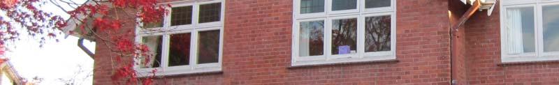
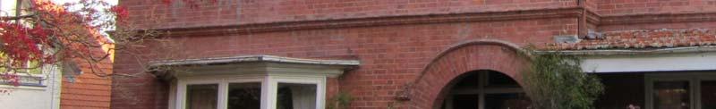
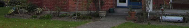
4 6--Jw-Geotech-R-69 Consulting Engineers of more than % when tested from the liquid limit in accordance with NZS Test.6 and, c) Any ground which could forseeably experience movement of mm or greater for any reason including one or a combination of the following: land instability, ground creep, subsidence (liquefaction, lateral spread for the Canterbury earthquake region only), seasonal swelling and shrinking, frost heave, changing ground water level, erosion, dissolution of soil in water, and effects of tree roots.. SITE DESCRIPTION The site is located at 6 Burnett St, Ashburton. Access to the property is via a l driveway off the south side of Burnett St. The legal description of the site is Lot DP 699 with an area of m. Figure. Screen Capture from QuickMap showing property location highlighted in black. The property has a flat contour. The existing dwelling is located in the middle of the property and is surrounded by wooden decks and gardens. A separate garage is located at the south eastern corner of the property. The building is a storied timber framed structure with unreinforced brick veneer supported on a concrete ring foundation. The structure has lightweight suspended timber floors supported on shallow concrete piles. A level survey inside the dwelling indicates it has undergone settlement of more than mm toward the south west. SITE DESCRIPTION
; grey river alluvium, comprising")
5 6--Jw-Geotech-R-69 Consulting Engineers. GEOLOGY The Institute of Geological and Nuclear Sciences Geological Map, Geology of the Aoraki Area, defines the geology of the site as river deposits (Qa and Qa); grey river alluvium, comprising gravel, sand and silt, in active floodplains (Qa) with grey river alluvium beneath plains or low-level terraces (Qa). The geology of the site is consistent with the overall geology of the Canterbury/Christchurch region. Figure. Institute of Geological and Nuclear Sciences Geology of the Aoraki Area Geological Map, showing the subject area highlighted in red.. SITE INVESTIGATIONS Recommended minimum investigations are specified in the EC Guidelines and NZGS Geotechnical Earthquake Engineering Practice Module : Guideline for the identification, assessment and mitigation of liquefaction hazards. Based on these guidelines we recommend that the minimum site investigations to confirm building suitability are: Continuous profile of the subsoil to firm basement (usually by borehole and/or CPT) Measurement of depth to water table GEOLOGY
6 6--Jw-Geotech-R-69 Consulting Engineers In-situ testing of all susceptible strata (usually by CPT or SPT) Sampling of all susceptible strata Grading curves for susceptible soils Atterberg limit tests for all soils.. Cone Penetration Testing Geotechnical field investigations were carried out on the th of May,. These investigations consisted of: Visual inspections and walkover. Seven cone penetration tests (CPT) to varying depths ranging from.7m to 6.m below the existing ground level The locations of all cone penetration tests are shown on the site plan attached as Appendix.... Subsoil CPT results have been analysed with results attached in Appendix and. Results of the soil behaviour plots show alternating layers of Silty CLAY, SILT and Sandy SILT down to approximately.-6m below ground. Some CPT tests (CPTs 6 & 7) show sensitive fine grained material, interpreted as organics (peat), at a depth of between and.6m. All of the CPTs refused on a competent layer interpreted as SAND and/or GRAVEL. The groundwater table ranges from.7m to.m below ground level across the site.. REQUIREMENTS AND GUIDELINES The Department of Housing and Building has provided the following guidelines: Enhanced foundations can be used on sites with potential for liquefaction provided lateral spreading across the property is less than mm. A slope over the building platform of.% ( in ) is acceptable after a liquefiable event. 6. ASSESSMENT OF LIQUEFACTION REQUIREMENTS AND GUIDELINES
7 6--Jw-Geotech-R-69 Consulting Engineers CPT results have been analysed to assess the potential for soil liquefaction and settlement. Results are attached in Appendix. The assessment of liquefaction has been undertaken under ultimate limit state design (ULS) criteria and serviceability limit state design (SLS) criteria. The ultimate limit state is reached when the applied stresses actually exceed the strength of the structure or structural elements causing it to fail or collapse. The serviceability limit state is the point where a structure can no longer be used for its intended purpose but would still be structurally sound. The tolerances for serviceability depend on the intended use of the structure and can vary significantly. 6.. Ultimate Limit State Design (ULS) 6... Design Parameters Design parameters have been calculated for analysing the CPT results. Calculation of the peak horizontal ground acceleration (PGA) has been calculated in accordance with NZS7.: using the following formula: Ah = Z R C Where: Z =. (base PGA called hazard factor given by NZS 7.:) R = ( in yr return period factor given by NZS 7.:) C =. (Site response factor called spectral shape factor, based on class of soil and given by NZS 7.:) Ah =. x x. =.99 m/s The magnitude earthquake recommended for all common liquefaction assessment procedures in Christchurch is M Results and Analysis The results of the 7 CPT investigations under ULS design earthquake parameters show that there is generally a low risk of liquefaction across the site. Only one test location, CPT 6 near the south western corner of the house, indicated a high risk of liquefaction at a depth of some m. The site is not in close proximity to a river of free excavated bank and is not considered subject to lateral spreading based on observations from aerial photographs. ASSESSMENT OF LIQUEFACTION

8 6--Jw-Geotech-R-69 Consulting Engineers The CPT investigations were undertaken around the outside of the building due to equipment access limitations. It is assumed that the variability between CPT results in close proximity will equally apply inside the building footprint. Vertical Settlement The CPT locations have been plotted below, and a filled contour plan of vertical settlements across the site has been generated. A larger version of this plan is attached in Appendix. Figure. Filled contour plan showing vertical settlement across the site under ULS design earthquake parameters. Maximum settlement under the design earthquake parameters due to liquefaction was calculated to be approximately 6mm at the location of CPT6 at the southwestern side of the dwelling. Results also show that the western side of the site is more prone to liquefaction with higher liquefaction potential indexes. The rest of the site has vertical settlements ranging from to mm. Although liquefaction is a major cause of earthquake damage, little harm occurs unless liquefaction generates some form of ground surface disruption or ground failure. A study undertaken by K. Ishihara in 9 presented preliminary empirical criteria for assessing the potential for ground surface disruption at liquefaction sites. The criteria are based on relationships between the thickness of liquefiable sediment beneath a site and the corresponding thickness of overlying non-liquefiable soil. A summary of the settlement results, depths to liquefiable layers, thickness of liquefiable layers and liquefaction potential index across the site are tabulated below: ASSESSMENT OF LIQUEFACTION 6
9 6--Jw-Geotech-R-69 Consulting Engineers CPT Settlement (mm) Depth to liquefied layer (m) Thickness of liquefied layer (m) Liquefaction Potential Index (RISK).. LOW.. LOW 6.. LOW..9 LOW 9.. LOW HIGH 7. LOW Table. Settlement, depths to liquefiable layers, thickness of liquefiable layers and liquefaction potential index for 7 CPT tests undertaken across the site. Figure. Graph showing thickness of surface layer vs. thickness of liquefiable layer with boundary curve from Ishihara for a maximum ground acceleration of.g. All data points above the line signify occurrence of surface effects of liquefaction. The assessment against data from Ishihara 9 shows that the thickness of the surface layer is generally adequate to prevent sand boils and small fissures coming to the ground surface with the exception at the location of CPT6. It is likely that surface effects of liquefaction will occur along the southern portion of the house. ASSESSMENT OF LIQUEFACTION 7
10 6--Jw-Geotech-R-69 Consulting Engineers Differential Settlement Differential settlement causes the most damage to structures. It is the differential vertical and horizontal displacements which cause stresses on the structure and induce damage to foundations, flooring, structural connections, cladding and the roof. Differential settlement has been calculated between CPT6 and CPT, giving an angular rotation of % under ULS design parameters which is inside the regulations. This is taken as rotation from one side of the building platform to the other. Maximum differential settlement is between CPT6 and CPT with an angular rotation of.%. However, these CPT s are in close proximity and the stresses resulting from the differential settlement are expected to be spread across the entire structure reducing rotation. 6.. Serviceability Limit State Design (SLS) 6... Design Parameters Design parameters have been calculated for analysing the CPT results. Calculation of the peak horizontal ground acceleration (PGA) has been calculated using: Ah = Z R C Where: Z =. (base PGA called hazard factor given by NZS 7.:) R =. ( in yr return period factor given by NZS 7.:) C =. (Site response factor called spectral shape factor, based on class of soil and given by NZS 7.:) Ah =. x. x. =. m/s The magnitude earthquake recommended for all common liquefaction assessment procedures in Christchurch is M Results and Analysis The results of the 7 CPT investigations show that there is a low risk of liquefaction under the SLS design earthquake parameters. Vertical Settlement The CPT locations have been plotted below, and a filled contour plan of vertical settlements across the site has been generated. A larger version of this plan is attached in Appendix. ASSESSMENT OF LIQUEFACTION
11 6--Jw-Geotech-R-69 Consulting Engineers Figure. Filled contour plan showing vertical settlement across the site under SLS design earthquake parameters. Maximum settlement under the SLS design earthquake parameters due to liquefaction was calculated to be approximately mm at the location of CPT along the western side of the dwelling. Settlements of up to mm were calculated at the location of CPT 7, at the south western corner of the dwelling. Calculation of liquefaction induced settlement at the other CPT locations indicates settlement. A summary of the settlement results, depths to liquefiable layers, thickness of liquefiable layers and liquefaction potential index across the site are tabulated below: CPT Settlement (mm) Depth to liquefied layer (m) Thickness of liquefied layer (m) Liquefaction Potential Index (RISK).. LOW... LOW.. LOW..7 LOW..9 LOW 6.. LOW 7.. LOW ASSESSMENT OF LIQUEFACTION 9
12 6--Jw-Geotech-R-69 Consulting Engineers Table. Settlement, depth to liquefiable layers, thickness of liquefiable layers and liquefaction potential index for 7 CPT tests under SLS design earthquake parameters. Figure 6. Graph showing thickness of surface layer vs. thickness of liquefiable layer with boundary curve from Ishihara for a maximum ground acceleration of.g. All data points above the line signify occurrence of surface effects of liquefaction. The liquefaction assessment using SLS design earthquake parameters shows that surface effects of liquefaction are not likely to occur during the design earthquake across the site. Differential Settlement Differential settlement has been calculated between CPT6 and CPT, giving an angular rotation of.% under SLS design parameters which is inside the regulations. This is taken as rotation from one side of the building platform to the other. Maximum differential settlement is between CPT6 and CPT with an angular rotation of.9%. However, these CPT s are in close proximity and the stresses resulting from the differential settlement are expected to be spread across the entire structure reducing rotation. ASSESSMENT OF LIQUEFACTION
13 6--Jw-Geotech-R-69 Consulting Engineers 6.. Summary A summary of the results from the liquefaction assessment under ultimate limit state design (ULS) criteria and serviceability limit state design (SLS) criteria is tabulated below: Design Criteria Liquefaction Potential Index (RISK) Maximum Vertical Settlement (mm) Expected Differential Settlement (% rotation) Maximum Differential Settlement (% rotation) ULS LOW to HIGH 6 %.% SLS LOW.%.9% Table. Summary of LPI, vertical settlement and differential settlement for 7 CPT tests taken across the site. 7. LIQUEFACTION REMEDIATION MEASURES Two approaches are generally used to mitigate liquefaction and its consequences:. Soil Remediation. Structural Modification While these are discussed herein it is generally impracticable with a building in place due to the impracticality of large machines working and the cost of working in confined spaces. 7.. Soil Remediation Soil remediation measures effectively reduce ground deformation and effects of liquefaction by preventing/limiting/slowing-down the development of excess pore water pressure and/or by limiting the development of shear strains and vertical strains in the ground. Soil remediation is usually based on one or a combination of the following measures: Densification (compaction, vibro-flotation, compaction piles, preloading) to increase liquefaction resistance and reduce deformability of the soil through increased strength and stiffness. Solidification (deep mixing, permeation grouting) through cementation of soils. Containment of liquefied soils and limitation of ground deformation by reinforcement and soil mixing walls. Drainage (pre-fabricated drains, stone columns) for increased permeability and faster dissipation of excess pore water pressures. LIQUEFACTION REMEDIATION MEASURES
14 6--Jw-Geotech-R-69 Consulting Engineers Results of the 7 CPT tests show that there is generally a low risk of liquefaction across the site with the exception of the southern end of the dwelling where a high risk was identified. An option for soil remediation that may be suitable at the site is vibro-replacement stone columns or deep soil mixing. This would need to be undertaken with the building removed and may not be practical in this instance. During the vibro-replacement method a probe cavity is filled with imported materials such as crushed stone, gravel or sometimes concrete. Vibro-replacement can improve the liquefiable soil by densification, increasing the lateral stress, reinforcing the soil mass with the stiffer columns of fill material and providing increased drainage of earthquake induced excess pore water pressures. Deep soil mixing involves the mixing, and sometimes partial replacement, of in-situ soils with cementitious materials or grout. Deep soil mixing uses mixing augers that inject the cementitious material or grout into the surrounding soil through the auger stems as they continue to rotate and mix the injected matter with the existing soils. Testing is required prior to deep soil mixing; using different levels of cementitious material mixed with the existing soil to find the ideal unconfined compressive strength. 7.. Structural Modification Potential effects of liquefaction can be taken into account and accommodated in the design or strengthening of the structure in order to reduce differential settlement. This is commonly achieved by using stiff raft, rigid foundation beams/walls or pile foundations with sufficient lateral capacity to resist both inertial loads due to vibration of the structure and kinematic loads due to ground movement. If the building is to be rebuilt and a stiffened raft option is selected, there is still potential for the whole structure to rotate. CPT results show that differential settlement will likely be above the minimum allowable angular rotation of.%. If no soil remediation measures are undertaken prior to the repair or re-build, then structural modification of the building will be required to reduce differential settlement to below the tolerance of.% angular rotation. If a repair strategy is approached, then the recommended option is to underpin the perimeter concrete foundation with flexible pile foundations. The piles should be extended through the liquefiable layer and pinned into the dense material below. This will require a specific engineered design at the building consent stage of development. LIQUEFACTION REMEDIATION MEASURES
15 6--Jw-Geotech-R-69 Consulting Engineers. STATIC SETTLEMENT BELOW FOUNDATIONS CPT results have been analysed to assess the level of static vertical settlement beneath foundations of future dwellings at the subdivision. Due to the identification of a fine grained sensitive soil in CPTs 6 and 7, we anticipate further static settlements along the south western portion of the structure. A foundation system consisting of a.m wide x.m deep strip footing (i.e. for a concrete slab floor) has been used for design purposes with a conservative kpa footing pressure. A length to breadth footing dimension ratio of has been used for the calculations. A summary of the static vertical settlement results are summarised below. CPT Static Vertical Settlement (mm) < < < < < 6 < 7 < Table. Summary of static vertical settlement at each CPT location. The results show ongoing static settlement across the site will be negligible. It is likely that the organic soils identified have already undergone settlement and some of the settlement observed in the level survey is a result of this. 9. STATIC BEARING CAPACITY OF FOUNDATIONS The ultimate bearing capacities for a.m wide x.m deep strip footing have been calculated with varying results between CPT test locations at the site. Allowable bearing capacity has been determined using a Factor of Safety of. Bearing capacity calculations are included in Appendix. Results shown in Table below show allowable bearing capacities vary significantly across the site. CPT Ultimate Bearing Capacity (kpa) Allowable Bearing Capacity (kpa) Dependable Bearing Capacity (kpa) 7 7 STATIC SETTLEMENT BELOW FOUNDATIONS

16 6--Jw-Geotech-R-69 Consulting Engineers Table. Summary of bearing capacity at each CPT location. Care is required as the density of the upper layers varies and heavy compaction below the foundations is recommended prior to construction. Generally the allowable bearing capacity should be in excess of kpa.. FOUNDATIONS Maximum vertical settlement at the site under SLS and ULS design earthquake parameters was found to be mm and 6mm, respectively. In accordance with the liquefaction deformation limits and house foundation implications (Table below, taken from DBH Guidelines), the vertical settlements are within the limits recommended for a TC site and therefore enhanced foundation solutions will be suitable (DBH Guidelines Section.). Table. DBH Guidelines for the Geotechnical Investigation and Assessment of Subdivisions in the Canterbury Region Liquefaction Deformation Limits and House Foundation Implications. The liquefaction analysis indicates that the building will be subject to ongoing settlement from SLS Serviceability Limit Loads and ULS Ultimate Limit Loads during the ongoing earthquake sequence that is being experienced in the Christchurch area. The CPTs identified a hard founding layer (gravel) at depths of between and 6m. The future foundations and building interaction will need to control horizontal and vertical differential settlement to ensure the induced concentrated stresses do not FOUNDATIONS
17 6--Jw-Geotech-R-69 Consulting Engineers damage the building. The resulting damage from an earthquake event should be able to be repairable through an earthquake sequence by re-levelling the building. Considering the thickness to the liquefying layer and geotechnical conclusions identifying the damage that has occurred to the building foundations treatment of the ground and/or repairing the foundations are required. This will require. Ground improvement. Reconstructing the building on a raft foundation. Completing these options with the building in place will be economically challenging. If soil remediation measures are undertaken, then a concrete slab floor of stiffened raft or rib raft design may be constructed directly on the ground surface. Options for soil remediation are:. Cement stabilisation with -6% cement re-worked into the existing ground up to m thick with building foundations constructed on this layer. This will act as a bridging layer and prevent liquefaction from reaching the surface. The stabilised pad should be extended at least.m past the building envelope.. Vibro replacement stone columns consisting 6mm diameter columns extended a minimum of -6m below ground level to be pinned into the un-liquefiable subsoil beneath. If no soil remediation is undertaken at the site, the following foundation option is recommended:. Construct an enhanced reinforced foundation wall. This would require underpinning the ring foundation by driving or boring flexible timber piles to below the un-liquefiable soils at a depth of some -6m. A replacement foundation wall could be constructed on top of these piles and tied into the existing foundation. This would require specific engineering design.. Re-level and repack the concrete piles supporting the timber floors and internal walls. It may be that some settlement occurs in future events and provision should be made to re-level the internal footings if this occurs. Alternatively, strengthening of the structure could restrict this settlement.. CONCLUSIONS AND RECOMMENDATIONS Geotechnical investigations indicate that the subsoil properties do not have strength parameters necessary for ongoing support of the existing building without ground improvement and/or repairing the foundation system. Allowable bearing capacity is CONCLUSIONS AND RECOMMENDATIONS
18 6--Jw-Geotech-R-69 Consulting Engineers variable across the building platform. A fine grained sensitive soil (peat) was identified along the south western portion of the dwelling. Design Criteria Liquefaction Potential Index (RISK) Maximum Vertical Settlement (mm) Expected Differential Settlement (% rotation) Maximum Differential Settlement (% rotation) ULS LOW to HIGH 6 %.% SLS LOW.%.9% Table. Summary of LPI, vertical settlement and differential settlement for 7 CPT tests taken across the site. Calculations to date using the design earthquake parameters from NZS7. show the following: SLS maximum dynamic settlement is approximately mm with an expected differential settlement across the building platform north-south of mm causing angular rotation of.%. ULS dynamic settlement is 6mm with an expected differential settlement across the building platform north-south of mm causing angular rotation of %. The un-liquefiable surface layer thickness is generally thick enough to prevent surface effects of liquefaction including sand boils and small fissures except along the south western portion of the house where surface effects of liquefaction may occur. It is advised that the building under ULS loading is flexible enough to allow these movements without collapse. The following recommendations are to be incorporated into the building construction:. It is recommended that soil remediation or a new foundation system at the site be constructed.. Soil remediation is recommended to prevent sand boils penetrating the ground surface, reduce differential settlement and maintain the integrity of the building. This is unlikely to be economically practicable with the building in place. a. One option for soil remediation is cement stabilisation of the top m subsoil with -6% cement re-worked into the existing ground. The stabilised pad should be extended at least.m past the building envelope. a. Option two for soil remediation is vibro replacement stone columns consisting of 6mm diameter columns extended a minimum of -6m below ground level to be pinned into the un-liquefiable subsoil beneath. CONCLUSIONS AND RECOMMENDATIONS 6
19 6--Jw-Geotech-R-69 Consulting Engineers. If soil remediation measures are undertaken then the foundations of the new building may be constructed directly on the re-worked ground. A concrete slab flooring system of rib raft or stiffened raft design is recommended. 6. If no soil remediation is undertaken at the site, the concrete ring foundation will need to be replaced with an enhanced reinforced foundation wall and underpinned with pile foundations to reduce differential settlement. Pile foundations will likely consist of -mm diameter driven timber piles pinned into the un-liquefiable subsoil beneath. The internal piles supporting the floor should be repacked and re-levelled with a provision for furthering re-levelling in the event of further events. 7. The ground is suitable for the construction of services and these should allow for being subjected to earthquake dynamic loads and liquefaction zones.. All re-build works should be carried out under the guidance of a Chartered Professional Engineer with relevant experience.. LIMITATIONS This report has been prepared for the benefit of MWH Mainzeal as our client with respect to geotechnical investigation for repair/reconstruction methodology as defined in the brief. It shall not be relied upon for any other purpose. The reliance by other parties on the information or opinions contained in this report shall, without our prior review and agreement in writing, be at such parties sole risk. Opinions and judgments expressed herein are based on our understanding and interpretation of current regulatory standards, and should not be construed as legal opinions. Where opinions or judgments are to be relied on they should be independently verified with appropriate legal advice. Any recommendations, opinions, or guidance provided by Cook Costello Ltd in this report are limited to technical engineering requirements and are not made under the Financial Advisers Act. Recommendations and opinions in this report are based on data from cone penetration testing undertaken on site. The nature and continuity of subsoil conditions away from the cone penetration tests are inferred and it must be appreciated that actual conditions could vary considerably from the assumed model. During excavation and construction the site should be examined by an Engineer or Engineering Geologist competent to judge whether the exposed subsoil s are compatible with the inferred conditions on which the report has been based. It is possible that the nature of the exposed subsoil s may require further investigation and the modification of the design based on this report. In any event it is essential that the LIMITATIONS 7
20 6--Jw-Geotech-R-69 Consulting Engineers firm is notified if there is any variation in subsoil conditions from those described in the report as it may affect the design parameters recommended in the report. Cook Costello Ltd. have performed the services for this project in accordance with the standard agreement for consulting services and current professional standards for environmental site assessment. guarantees are either expressed or implied. There is no investigation which is thorough enough to preclude the presence of materials at the site which presently, or in the future, may be considered hazardous. Because regulatory evaluation criteria are constantly changing, concentrations of contaminants present and considered to be acceptable now may in the future become subject to different regulatory standards which cause them to become unacceptable and require further remediation for this site to be suitable for the existing or proposed land use activities. J T Walker Engineering Geologist BScGE, MIPENZ, P J Cook Chartered Professional Engineer BE(hons),Dip Ag, CPEng, MIPENZ, IntPE(NZ), MACENZ, MIOD LIMITATIONS
21 6--Jw-Geotech-R-69 Consulting Engineers. APPENDIX : SITE PLANS APPENDIX : SITE PLANS 9
22
23 6--Jw-Geotech-R-69 Consulting Engineers. APPENDIX : CPT ANALYSIS APPENDIX : CPT ANALYSIS
24 Project: Location: Cook Costello Consulting Engineers Christchurch Liquefaction Assessment 6-: 6 Burnett St, Ashburton CPT: CPT- Total depth:.7 m, Date: 7/6/ Surface Elevation:. m Coords: X:., Y:. Cone Type: Uknown Cone Operator: Uknown Settlements calculation according to theory of elasticity * Cone Cone resistance qt qt Constrained Modulus Cumulative settlement End of Primary Ov erall Tip resistance (MPa) M(C PT) (MPa).. Settlement (cm). Caclulation properties Footing type: Rectangular Footing width:. (m) L/B: Footing pressure:. (kpa) Embedment depth:. (m) Footing is rigid: Remove excavation load: Apply % rule: Calculate secondary settlements: Time period for second. settlements: * Primary settlements calculation is performed according to the following formula: S * Secondary (creep) settlements calculation is performed according to the following formula: S C a CPT v z z log( t) CPeT-IT v CPTU data presentation & interpretation software - Report created on: 6/7/, :: p.m. Project file: C:\Users\Jordan\Documents\Cook Costello\6\ Burnett Street\Calculations\6- CPe-IT.cpt
25 CPT name: CPT- :: Tabular results :: Point Start depth (m) End depth (m) Thickness (m) Relative depth (m) Delta P (kpa) M (CPT) (MPa) Iz Settlement (cm) Second. settlement (cm) Overall settlement (cm) CPeT-IT v CPTU data presentation & interpretation software - Report created on: 6/7/, :: p.m. Project file: C:\Users\Jordan\Documents\Cook Costello\6\ Burnett Street\Calculations\6- CPe-IT.cpt
26 CPT name: CPT- :: Tabular results :: Point Start depth (m) End depth (m) Thickness (m) Relative depth (m) Delta P (kpa) M (CPT) (MPa) Iz Settlement (cm) Second. settlement (cm) Overall settlement (cm) Total primary settlement:. Total secondary settlement:. Total calculated settlement:. Abbreviations Start depth: End depth: Thickness: Relative depth: Iz: Delta P: Eff. stress: M (CPT): Settlement: Second. settlement: Start depth of soil layer (penetration depth measured from ground free surface) End depth of soil layer (penetration depth measured from ground free surface) Thickness of soil layer Depth of calculation relative to footing Stress influence factor Footing impossed stress: Effective stress Constrained modulus from CPT Primary settlement Secondary settlemends due to creep CPeT-IT v CPTU data presentation & interpretation software - Report created on: 6/7/, :: p.m. Project file: C:\Users\Jordan\Documents\Cook Costello\6\ Burnett Street\Calculations\6- CPe-IT.cpt
27 Project: Location: Cook Costello Consulting Engineers Christchurch Liquefaction Assessment 6-: 6 Burnett St, Ashburton CPT: CPT- Total depth:.7 m, Date: 7/6/ Surface Elevation:. m Coords: X:., Y:. Cone Type: Uknown Cone Operator: Uknown Bearing Bearing Capacity Capacity Plot Plot,, 9 96 Bearing Capacity calculation is perfromed based on the formula: Q ult R k q t q soil Ultimate Bearing Capacity (kpa) where: R k: Bearing capacity factor q t: Average corrected cone resistance over calculation depth q soil: Pressure applied by soil above footing Footing Width (m) :: Tabular results :: B (m) Start Depth (m) End Depth (m) Ave. q t (MPa) R k Soil Press. (kpa) Ult. bearing cap. (kpa) CPeT-IT v CPTU data presentation & interpretation software - Report created on: 6/7/, :: p.m. Project file: C:\Users\Jordan\Documents\Cook Costello\6\ Burnett Street\Calculations\6- CPe-IT.cpt
28 Project: Location: Cook Costello Consulting Engineers Christchurch Liquefaction Assessment 6-: 6 Burnett St, Ashburton CPT: CPT- Total depth:.67 m, Date: 7/6/ Surface Elevation:. m Coords: X:., Y:. Cone Type: Uknown Cone Operator: Uknown Settlements calculation according to theory of elasticity * Cone Cone resistance qt qt Constrained Modulus Cumulative settlement.... End of Primary Ov erall Tip resistance (MPa) M(C PT) (MPa) 6 Settlement (cm) Caclulation properties Footing type: Rectangular Footing width:. (m) L/B: Footing pressure:. (kpa) Embedment depth:. (m) Footing is rigid: Remove excavation load: Apply % rule: Calculate secondary settlements: Time period for second. settlements: * Primary settlements calculation is performed according to the following formula: S * Secondary (creep) settlements calculation is performed according to the following formula: S C a CPT v z z log( t) CPeT-IT v CPTU data presentation & interpretation software - Report created on: 6/7/, :: p.m. Project file: C:\Users\Jordan\Documents\Cook Costello\6\ Burnett Street\Calculations\6- CPe-IT.cpt
29 CPT name: CPT- :: Tabular results :: Point Start depth (m) End depth (m) Thickness (m) Relative depth (m) Delta P (kpa) M (CPT) (MPa) Iz Settlement (cm) Second. settlement (cm) Overall settlement (cm) Total primary settlement:. Total secondary settlement:. Total calculated settlement:. Abbreviations Start depth: End depth: Thickness: Relative depth: Iz: Delta P: Eff. stress: M (CPT): Settlement: Second. settlement: Start depth of soil layer (penetration depth measured from ground free surface) End depth of soil layer (penetration depth measured from ground free surface) Thickness of soil layer Depth of calculation relative to footing Stress influence factor Footing impossed stress: Effective stress Constrained modulus from CPT Primary settlement Secondary settlemends due to creep CPeT-IT v CPTU data presentation & interpretation software - Report created on: 6/7/, :: p.m. 6 Project file: C:\Users\Jordan\Documents\Cook Costello\6\ Burnett Street\Calculations\6- CPe-IT.cpt
30 Project: Location: Cook Costello Consulting Engineers Christchurch Liquefaction Assessment 6-: 6 Burnett St, Ashburton CPT: CPT- Total depth:.67 m, Date: 7/6/ Surface Elevation:. m Coords: X:., Y:. Cone Type: Uknown Cone Operator: Uknown Bearing Bearing Capacity Plot Plot Bearing Capacity calculation is perfromed based on the formula: Q ult R k q t q soil Ultimate Bearing Capacity (kpa) where: R k: Bearing capacity factor q t: Average corrected cone resistance over calculation depth q soil: Pressure applied by soil above footing 9 Footing Width (m) :: Tabular results :: B (m) Start Depth (m) End Depth (m) Ave. q t (MPa) R k Soil Press. (kpa) Ult. bearing cap. (kpa) CPeT-IT v CPTU data presentation & interpretation software - Report created on: 6/7/, :: p.m. 7 Project file: C:\Users\Jordan\Documents\Cook Costello\6\ Burnett Street\Calculations\6- CPe-IT.cpt
31 Project: Location: Cook Costello Consulting Engineers Christchurch Liquefaction Assessment 6-: 6 Burnett St, Ashburton CPT: CPT- Total depth:.97 m, Date: 7/6/ Surface Elevation:. m Coords: X:., Y:. Cone Type: Uknown Cone Operator: Uknown Settlements calculation according to theory of elasticity * Cone Cone resistance qt qt Constrained Modulus Cumulative settlement.... End of Primary Ov erall Tip resistance (MPa) 9 M(C PT) (MPa) 9 Settlement (cm) Caclulation properties Footing type: Rectangular Footing width:. (m) L/B: Footing pressure:. (kpa) Embedment depth:. (m) Footing is rigid: Remove excavation load: Apply % rule: Calculate secondary settlements: Time period for second. settlements: * Primary settlements calculation is performed according to the following formula: S * Secondary (creep) settlements calculation is performed according to the following formula: S C a CPT v z z log( t) CPeT-IT v CPTU data presentation & interpretation software - Report created on: 6/7/, :: p.m. Project file: C:\Users\Jordan\Documents\Cook Costello\6\ Burnett Street\Calculations\6- CPe-IT.cpt
32 CPT name: CPT- :: Tabular results :: Point Start depth (m) End depth (m) Thickness (m) Relative depth (m) Delta P (kpa) M (CPT) (MPa) Iz Settlement (cm) Second. settlement (cm) Overall settlement (cm) Total primary settlement:. Total secondary settlement:. Total calculated settlement:. Abbreviations Start depth: End depth: Thickness: Relative depth: Iz: Delta P: Eff. stress: M (CPT): Settlement: Second. settlement: Start depth of soil layer (penetration depth measured from ground free surface) End depth of soil layer (penetration depth measured from ground free surface) Thickness of soil layer Depth of calculation relative to footing Stress influence factor Footing impossed stress: Effective stress Constrained modulus from CPT Primary settlement Secondary settlemends due to creep CPeT-IT v CPTU data presentation & interpretation software - Report created on: 6/7/, :: p.m. 9 Project file: C:\Users\Jordan\Documents\Cook Costello\6\ Burnett Street\Calculations\6- CPe-IT.cpt
33 Project: Location: Cook Costello Consulting Engineers Christchurch Liquefaction Assessment 6-: 6 Burnett St, Ashburton CPT: CPT- Total depth:.97 m, Date: 7/6/ Surface Elevation:. m Coords: X:., Y:. Cone Type: Uknown Cone Operator: Uknown 6 Bearing Bearing Capacity Plot Plot Bearing Capacity calculation is perfromed based on the formula: Q ult R k q t q soil Ultimate Bearing Capacity (kpa) 6 6 where: R k: Bearing capacity factor q t: Average corrected cone resistance over calculation depth q soil: Pressure applied by soil above footing Footing Width (m) :: Tabular results :: B (m) Start Depth (m) End Depth (m) Ave. q t (MPa) R k Soil Press. (kpa) Ult. bearing cap. (kpa) CPeT-IT v CPTU data presentation & interpretation software - Report created on: 6/7/, :: p.m. Project file: C:\Users\Jordan\Documents\Cook Costello\6\ Burnett Street\Calculations\6- CPe-IT.cpt
34 Project: Location: Cook Costello Consulting Engineers Christchurch Liquefaction Assessment 6-: 6 Burnett St, Ashburton CPT: CPT- Total depth:.9 m, Date: 7/6/ Surface Elevation:. m Coords: X:., Y:. Cone Type: Uknown Cone Operator: Uknown Settlements calculation according to theory of elasticity * Cone Cone resistance qt qt Constrained Modulus Cumulative settlement.... End of Primary Ov erall Tip resistance (MPa) M(C PT) (MPa) Settlement (cm) Caclulation properties Footing type: Rectangular Footing width:. (m) L/B: Footing pressure:. (kpa) Embedment depth:. (m) Footing is rigid: Remove excavation load: Apply % rule: Calculate secondary settlements: Time period for second. settlements: * Primary settlements calculation is performed according to the following formula: S * Secondary (creep) settlements calculation is performed according to the following formula: S C a CPT v z z log( t) CPeT-IT v CPTU data presentation & interpretation software - Report created on: 6/7/, :: p.m. Project file: C:\Users\Jordan\Documents\Cook Costello\6\ Burnett Street\Calculations\6- CPe-IT.cpt
35 CPT name: CPT- :: Tabular results :: Point Start depth (m) End depth (m) Thickness (m) Relative depth (m) Delta P (kpa) M (CPT) (MPa) Iz Settlement (cm) Second. settlement (cm) Overall settlement (cm) Total primary settlement:. Total secondary settlement:. Total calculated settlement:. Abbreviations Start depth: End depth: Thickness: Relative depth: Iz: Delta P: Eff. stress: M (CPT): Settlement: Second. settlement: Start depth of soil layer (penetration depth measured from ground free surface) End depth of soil layer (penetration depth measured from ground free surface) Thickness of soil layer Depth of calculation relative to footing Stress influence factor Footing impossed stress: Effective stress Constrained modulus from CPT Primary settlement Secondary settlemends due to creep CPeT-IT v CPTU data presentation & interpretation software - Report created on: 6/7/, :: p.m. Project file: C:\Users\Jordan\Documents\Cook Costello\6\ Burnett Street\Calculations\6- CPe-IT.cpt
36 Project: Location: Cook Costello Consulting Engineers Christchurch Liquefaction Assessment 6-: 6 Burnett St, Ashburton CPT: CPT- Total depth:.9 m, Date: 7/6/ Surface Elevation:. m Coords: X:., Y:. Cone Type: Uknown Cone Operator: Uknown Bearing Bearing Capacity Plot Plot 9 7 Bearing Capacity calculation is perfromed based on the formula: Q ult R k q t q soil where: R k: Bearing capacity factor q t: Average corrected cone resistance over calculation depth q soil: Pressure applied by soil above footing Ultimate Bearing Capacity (kpa) Footing Width (m) :: Tabular results :: B (m) Start Depth (m) End Depth (m) Ave. q t (MPa) R k Soil Press. (kpa) Ult. bearing cap. (kpa) CPeT-IT v CPTU data presentation & interpretation software - Report created on: 6/7/, :: p.m. Project file: C:\Users\Jordan\Documents\Cook Costello\6\ Burnett Street\Calculations\6- CPe-IT.cpt
37 Project: Location: Cook Costello Consulting Engineers Christchurch Liquefaction Assessment 6-: 6 Burnett St, Ashburton CPT: CPT- Total depth:.6 m, Date: 7/6/ Surface Elevation:. m Coords: X:., Y:. Cone Type: Uknown Cone Operator: Uknown Settlements calculation according to theory of elasticity * Cone Cone resistance qt qt Constrained Modulus Cumulative settlement End of Primary Ov erall Tip resistance (MPa) 7 9 M(C PT) (MPa) Settlement (cm) Caclulation properties Footing type: Rectangular Footing width:. (m) L/B: Footing pressure:. (kpa) Embedment depth:. (m) Footing is rigid: Remove excavation load: Apply % rule: Calculate secondary settlements: Time period for second. settlements: * Primary settlements calculation is performed according to the following formula: S * Secondary (creep) settlements calculation is performed according to the following formula: S C a CPT v z z log( t) CPeT-IT v CPTU data presentation & interpretation software - Report created on: 6/7/, :: p.m. Project file: C:\Users\Jordan\Documents\Cook Costello\6\ Burnett Street\Calculations\6- CPe-IT.cpt
38 CPT name: CPT- :: Tabular results :: Point Start depth (m) End depth (m) Thickness (m) Relative depth (m) Delta P (kpa) M (CPT) (MPa) Iz Settlement (cm) Second. settlement (cm) Overall settlement (cm) Total primary settlement:. Total secondary settlement:. Total calculated settlement:. Abbreviations Start depth: End depth: Thickness: Relative depth: Iz: Delta P: Eff. stress: M (CPT): Settlement: Second. settlement: Start depth of soil layer (penetration depth measured from ground free surface) End depth of soil layer (penetration depth measured from ground free surface) Thickness of soil layer Depth of calculation relative to footing Stress influence factor Footing impossed stress: Effective stress Constrained modulus from CPT Primary settlement Secondary settlemends due to creep CPeT-IT v CPTU data presentation & interpretation software - Report created on: 6/7/, :: p.m. Project file: C:\Users\Jordan\Documents\Cook Costello\6\ Burnett Street\Calculations\6- CPe-IT.cpt
39 Project: Location: Cook Costello Consulting Engineers Christchurch Liquefaction Assessment 6-: 6 Burnett St, Ashburton CPT: CPT- Total depth:.6 m, Date: 7/6/ Surface Elevation:. m Coords: X:., Y:. Cone Type: Uknown Cone Operator: Uknown 9 Bearing Bearing Capacity Plot Plot Bearing Capacity calculation is perfromed based on the formula: Q ult R k q t q soil where: R k: Bearing capacity factor q t: Average corrected cone resistance over calculation depth q soil: Pressure applied by soil above footing Ultimate Bearing Capacity (kpa) Footing Width (m) :: Tabular results :: B (m) Start Depth (m) End Depth (m) Ave. q t (MPa) R k Soil Press. (kpa) Ult. bearing cap. (kpa) CPeT-IT v CPTU data presentation & interpretation software - Report created on: 6/7/, :: p.m. 6 Project file: C:\Users\Jordan\Documents\Cook Costello\6\ Burnett Street\Calculations\6- CPe-IT.cpt
40 Project: Location: Cook Costello Consulting Engineers Christchurch Liquefaction Assessment 6-: 6 Burnett St, Ashburton CPT: CPT-6 Total depth:.7 m, Date: 7/6/ Surface Elevation:. m Coords: X:., Y:. Cone Type: Uknown Cone Operator: Uknown Settlements calculation according to theory of elasticity * Cone Cone resistance qt qt Constrained Modulus Cumulative settlement End of Primary Ov erall Tip resistance (MPa) M(C PT) (MPa) Settlement (cm). Caclulation properties Footing type: Rectangular Footing width:. (m) L/B: Footing pressure:. (kpa) Embedment depth:. (m) Footing is rigid: Remove excavation load: Apply % rule: Calculate secondary settlements: Time period for second. settlements: * Primary settlements calculation is performed according to the following formula: S * Secondary (creep) settlements calculation is performed according to the following formula: S C a CPT v z z log( t) CPeT-IT v CPTU data presentation & interpretation software - Report created on: 6/7/, :: p.m. 7 Project file: C:\Users\Jordan\Documents\Cook Costello\6\ Burnett Street\Calculations\6- CPe-IT.cpt
41 CPT name: CPT-6 :: Tabular results :: Point Start depth (m) End depth (m) Thickness (m) Relative depth (m) Delta P (kpa) M (CPT) (MPa) Iz Settlement (cm) Second. settlement (cm) Overall settlement (cm) CPeT-IT v CPTU data presentation & interpretation software - Report created on: 6/7/, :: p.m. Project file: C:\Users\Jordan\Documents\Cook Costello\6\ Burnett Street\Calculations\6- CPe-IT.cpt
42 CPT name: CPT-6 :: Tabular results :: Point Start depth (m) End depth (m) Thickness (m) Relative depth (m) Delta P (kpa) M (CPT) (MPa) Iz Settlement (cm) Second. settlement (cm) Overall settlement (cm) Total primary settlement:. Total secondary settlement:. Total calculated settlement:. Abbreviations Start depth: End depth: Thickness: Relative depth: Iz: Delta P: Eff. stress: M (CPT): Settlement: Second. settlement: Start depth of soil layer (penetration depth measured from ground free surface) End depth of soil layer (penetration depth measured from ground free surface) Thickness of soil layer Depth of calculation relative to footing Stress influence factor Footing impossed stress: Effective stress Constrained modulus from CPT Primary settlement Secondary settlemends due to creep CPeT-IT v CPTU data presentation & interpretation software - Report created on: 6/7/, :: p.m. 9 Project file: C:\Users\Jordan\Documents\Cook Costello\6\ Burnett Street\Calculations\6- CPe-IT.cpt
43 Project: Location: Cook Costello Consulting Engineers Christchurch Liquefaction Assessment 6-: 6 Burnett St, Ashburton CPT: CPT-6 Total depth:.7 m, Date: 7/6/ Surface Elevation:. m Coords: X:., Y:. Cone Type: Uknown Cone Operator: Uknown 6 Bearing Bearing Capacity Plot Plot 7 Bearing Capacity calculation is perfromed based on the formula: Q ult R k q t q soil where: R k: Bearing capacity factor q t: Average corrected cone resistance over calculation depth q soil: Pressure applied by soil above footing Ultimate Bearing Capacity (kpa) Footing Width (m) :: Tabular results :: B (m) Start Depth (m) End Depth (m) Ave. q t (MPa) R k Soil Press. (kpa) Ult. bearing cap. (kpa) CPeT-IT v CPTU data presentation & interpretation software - Report created on: 6/7/, ::6 p.m. Project file: C:\Users\Jordan\Documents\Cook Costello\6\ Burnett Street\Calculations\6- CPe-IT.cpt
44 Project: Location: Cook Costello Consulting Engineers Christchurch Liquefaction Assessment 6-: 6 Burnett St, Ashburton CPT: CPT-7 Total depth:. m, Date: 7/6/ Surface Elevation:. m Coords: X:., Y:. Cone Type: Uknown Cone Operator: Uknown Settlements calculation according to theory of elasticity * Cone Cone resistance qt qt Constrained Modulus Cumulative settlement End of Primary Ov erall Tip resistance (MPa) 6 7 M(C PT) (MPa).. Settlement (cm). Caclulation properties Footing type: Rectangular Footing width:. (m) L/B: Footing pressure:. (kpa) Embedment depth:. (m) Footing is rigid: Remove excavation load: Apply % rule: Calculate secondary settlements: Time period for second. settlements: * Primary settlements calculation is performed according to the following formula: S * Secondary (creep) settlements calculation is performed according to the following formula: S C a CPT v z z log( t) CPeT-IT v CPTU data presentation & interpretation software - Report created on: 6/7/, ::6 p.m. Project file: C:\Users\Jordan\Documents\Cook Costello\6\ Burnett Street\Calculations\6- CPe-IT.cpt
45 CPT name: CPT-7 :: Tabular results :: Point Start depth (m) End depth (m) Thickness (m) Relative depth (m) Delta P (kpa) M (CPT) (MPa) Iz Settlement (cm) Second. settlement (cm) Overall settlement (cm) CPeT-IT v CPTU data presentation & interpretation software - Report created on: 6/7/, ::6 p.m. Project file: C:\Users\Jordan\Documents\Cook Costello\6\ Burnett Street\Calculations\6- CPe-IT.cpt
46 CPT name: CPT-7 :: Tabular results :: Point Start depth (m) End depth (m) Thickness (m) Relative depth (m) Delta P (kpa) M (CPT) (MPa) Iz Settlement (cm) Second. settlement (cm) Overall settlement (cm) Total primary settlement:. Total secondary settlement:. Total calculated settlement:. Abbreviations Start depth: End depth: Thickness: Relative depth: Iz: Delta P: Eff. stress: M (CPT): Settlement: Second. settlement: Start depth of soil layer (penetration depth measured from ground free surface) End depth of soil layer (penetration depth measured from ground free surface) Thickness of soil layer Depth of calculation relative to footing Stress influence factor Footing impossed stress: Effective stress Constrained modulus from CPT Primary settlement Secondary settlemends due to creep CPeT-IT v CPTU data presentation & interpretation software - Report created on: 6/7/, ::6 p.m. Project file: C:\Users\Jordan\Documents\Cook Costello\6\ Burnett Street\Calculations\6- CPe-IT.cpt

47 Project: Location: Cook Costello Consulting Engineers Christchurch Liquefaction Assessment 6-: 6 Burnett St, Ashburton CPT: CPT-7 Total depth:. m, Date: 7/6/ Surface Elevation:. m Coords: X:., Y:. Cone Type: Uknown Cone Operator: Uknown,6,6,, Bearing Bearing Capacity Capacity Plot Plot Bearing Capacity calculation is perfromed based on the formula: Q ult R k q t q soil Ultimate Bearing Capacity (kpa),,,,,,,,,, 9 9 where: R k: Bearing capacity factor q t: Average corrected cone resistance over calculation depth q soil: Pressure applied by soil above footing 7 Footing Width (m) :: Tabular results :: B (m) Start Depth (m) End Depth (m) Ave. q t (MPa) R k Soil Press. (kpa) Ult. bearing cap. (kpa) CPeT-IT v CPTU data presentation & interpretation software - Report created on: 6/7/, ::6 p.m. Project file: C:\Users\Jordan\Documents\Cook Costello\6\ Burnett Street\Calculations\6- CPe-IT.cpt
48 6--Jw-Geotech-R-69 Consulting Engineers. APPENDIX : LIQUEFACTION ASSESSMENT APPENDIX : LIQUEFACTION ASSESSMENT
49 Cook Costello Consulting Engineers Christchurch Project title : Liquefaction Assessment - ULS Location : 6-: 6 Burnett St, Ashburton Overall Liquefaction Potential Index report LPI color scheme Very high risk High risk Low risk LPI value Basic statistics Total CPT number: 7.7% low risk.9% high risk.% very high risk CPT- CPT- CPT- CPT- CPT- CPT-6 CPT CPTU name CLiq v CPT Liquefaction Assessment Software Project file: C:\Users\Jordan\Documents\Cook Costello\6\ Burnett Street\Calculations\6- CLiq ULS.clq
50 Cook Costello Consulting Engineers Christchurch Project title : Liquefaction Assessment - ULS Location : 6-: 6 Burnett St, Ashburton Overall vertical settlements report Vertical settlement (cm) CPT- CPT- CPT- CPT- CPT- CPT-6 CPT CPTU name CLiq v CPT Liquefaction Assessment Software Project file: C:\Users\Jordan\Documents\Cook Costello\6\ Burnett Street\Calculations\6- CLiq ULS.clq
51
52 Project title : Liquefaction Assessment - ULS CPT file : CPT- Cone Cone resistance NCEER (99) NCEER (99) 7.. Cook Costello Consulting Engineers Christchurch LIQ UEFACTION ANALYSIS REPORT G.W.T. (in-situ): G.W.T. (earthq.): Friction Ratio Location : 6-: 6 Burnett St, Ashburton. m.6 m.6 SBTn Plot Plot Trans. detect. applied: CRR CRR plot plot like behavior applied: FS FS Plot Plot During earthq During earthq. 6 qt (MPa) 6 Rf (%) Ic (Robertson 99).. CRR & CSR.. Factor of safety Liquefaction M w=7 /, sigma ' = atm base curve, Summary of liquefaction potential Cyclic Stress Ratio* (CSR*).... rmalized CPT penetration resistance. 6 Qtn,cs Liquefaction 6. rmalized friction ratio (%) Zone A : Cyclic liquefaction likely depending on size and duration of cyclic loading Zone A : Cyclic liquefaction and strength loss likely depending on loading and ground geometry Zone B: Liquefaction and post-earthquake strength loss unlikely, check cyclic softening Zone C: Cyclic liquefaction and strength loss possible depending on soil plasticity, brittleness/sensitivity, strain to peak undrained strength and ground geometry CLiq v CPT Liquefaction Assessment Software - Report created on: 7/6/, :: p.m. Project file: C:\Users\Jordan\Documents\Cook Costello\6\ Burnett Street\Calculations\6- CLiq ULS.clq
53 CPT name: CPT- CPT basic interpretation plots.. Cone Cone resistance.. Friction Friction Ratio Ratio.. Pore Pore pressure.. SBT SBT Plot Plot.. Soil Soil Behaviour Type Type Sensitive fine grained Insitu qt (MPa) 6 Rf (%) u (kpa) Ic(SBT) 6 SBT (Robertson et al. 96) 6 NCEER (99) NCEER (99) 7... m.6 m.6 like behavior applied: SBT legend. Sensitive fine grained. Organic material. to silty clay. ey silt to silty. Silty sand to sandy silt 6. Clean sand to silty sand 7. Gravely sand to sand. Very stiff sand to 9. Very stiff fine grained CLiq v CPT Liquefaction Assessment Software - Report created on: 7/6/, :: p.m. Project file: C:\Users\Jordan\Documents\Cook Costello\6\ Burnett Street\Calculations\6- CLiq ULS.clq
54 CPT name: CPT- CPT basic interpretation plots (normalized) rm. rm. cone cone resistance rm. rm. friction friction ratio ratio m. m. pore pore pressure ratio ratio SBTn SBTn Plot Plot rm. rm. Soil Soil Behaviour Type Type Sand & silty sand Sand & silty sand Sand & silty sand Sand & silty sand Sand & silty sand Qtn 6 Fr (%) -... Bq Ic (Robertson 99) 6 SBTn (Robertson 99) 6 NCEER (99) NCEER (99) 7... m.6 m.6 like behavior applied: SBTn legend. Sensitive fine grained. Organic material. to silty clay. ey silt to silty. Silty sand to sandy silt 6. Clean sand to silty sand 7. Gravely sand to sand. Very stiff sand to 9. Very stiff fine grained CLiq v CPT Liquefaction Assessment Software - Report created on: 7/6/, :: p.m. Project file: C:\Users\Jordan\Documents\Cook Costello\6\ Burnett Street\Calculations\6- CLiq ULS.clq
55 Total Total cone cone resistance Liquefaction analysis overall plots (intermediate results) SBTn SBTn Index Index rm. rm. cone cone resistance Grain Grain char. char. factor factor CPT name: CPT- Corrected norm. norm. cone cone resistance qt (MPa) Ic (Robertson 99) Qtn Kc Qtn,cs NCEER (99) NCEER (99) 7... m.6 m.6 like behavior applied: CLiq v CPT Liquefaction Assessment Software - Report created on: 7/6/, :: p.m. Project file: C:\Users\Jordan\Documents\Cook Costello\6\ Burnett Street\Calculations\6- CLiq ULS.clq
56 CPT name: CPT- Liquefaction analysis overall plots CRR CRR plot plot FS Plot FS Plot Liquefaction potential Vertical settlements Lateral Lateral displacements During earthq..6. During earthq CRR & CSR.. Factor of safety LPI...6. Settlement (cm). Displacement (cm) NCEER (99) NCEER (99) 7... m.6 m.6 like behavior applied: F.S. color scheme Almost certain it will liquefy Very likely to liquefy Liquefaction and no liquefaction are equally likely Unlike to liquefy Almost certain it will not liquefy LPI color scheme Very high risk High risk Low risk CLiq v CPT Liquefaction Assessment Software - Report created on: 7/6/, :: p.m. Project file: C:\Users\Jordan\Documents\Cook Costello\6\ Burnett Street\Calculations\6- CLiq ULS.clq
57 rm. rm. cone cone resistance Check for strength loss plots (Olsen & Stark ()) Grain Grain char. char. factor factor Corrected norm. cone cone resistance SBTn SBTn Index Index CPT name: CPT- Liquefied Su/Sig'v Peak Su ratio Liq. Su ratio 6 6 Qtn Kc Qtn,cs Ic (Robertson 99)... Su/Sig'v.. NCEER (99) NCEER (99) 7... m.6 m.6 like behavior applied: CLiq v CPT Liquefaction Assessment Software - Report created on: 7/6/, :: p.m. 6 Project file: C:\Users\Jordan\Documents\Cook Costello\6\ Burnett Street\Calculations\6- CLiq ULS.clq
58 Project title : Liquefaction Assessment - ULS CPT file : CPT- Cone Cone resistance qt (MPa) NCEER (99) NCEER (99) Cook Costello Consulting Engineers Christchurch LIQ UEFACTION ANALYSIS REPORT G.W.T. (in-situ): G.W.T. (earthq.): Friction Ratio 6 Rf (%) Location : 6-: 6 Burnett St, Ashburton. m. m.6 SBTn Plot Plot Ic (Robertson 99) Trans. detect. applied: CRR CRR plot plot During earthq... CRR & CSR like behavior applied: FS FS Plot Plot During earthq... Factor of safety Liquefaction M w=7 /, sigma ' = atm base curve, Summary of liquefaction potential Cyclic Stress Ratio* (CSR*).... rmalized CPT penetration resistance. 6 Qtn,cs Liquefaction 6. rmalized friction ratio (%) Zone A : Cyclic liquefaction likely depending on size and duration of cyclic loading Zone A : Cyclic liquefaction and strength loss likely depending on loading and ground geometry Zone B: Liquefaction and post-earthquake strength loss unlikely, check cyclic softening Zone C: Cyclic liquefaction and strength loss possible depending on soil plasticity, brittleness/sensitivity, strain to peak undrained strength and ground geometry CLiq v CPT Liquefaction Assessment Software - Report created on: 7/6/, :: p.m. Project file: C:\Users\Jordan\Documents\Cook Costello\6\ Burnett Street\Calculations\6- CLiq ULS.clq 7
59 CPT name: CPT- CPT basic interpretation plots Cone Cone resistance Friction Friction Ratio Ratio Pore Pore pressure SBT SBT Plot Plot Soil Soil Behaviour Type Type Insitu qt (MPa)..6 6 Rf (%) u (kpa) Ic(SBT)..6 6 SBT (Robertson et al. 96) 6 NCEER (99) NCEER (99) 7... m. m.6 like behavior applied: SBT legend. Sensitive fine grained. Organic material. to silty clay. ey silt to silty. Silty sand to sandy silt 6. Clean sand to silty sand 7. Gravely sand to sand. Very stiff sand to 9. Very stiff fine grained CLiq v CPT Liquefaction Assessment Software - Report created on: 7/6/, :: p.m. Project file: C:\Users\Jordan\Documents\Cook Costello\6\ Burnett Street\Calculations\6- CLiq ULS.clq
60 CPT name: CPT- CPT basic interpretation plots (normalized) rm. rm. cone cone resistance.. rm. rm. friction friction ratio ratio m. m. pore pore pressure ratio ratio.. SBTn SBTn Plot Plot. rm. rm. Soil Soil Behaviour Type Type Qtn..6 6 Fr (%) Bq..6 Ic (Robertson 99)..6 6 SBTn (Robertson 99) 6 NCEER (99) NCEER (99) 7... m. m.6 like behavior applied: SBTn legend. Sensitive fine grained. Organic material. to silty clay. ey silt to silty. Silty sand to sandy silt 6. Clean sand to silty sand 7. Gravely sand to sand. Very stiff sand to 9. Very stiff fine grained CLiq v CPT Liquefaction Assessment Software - Report created on: 7/6/, :: p.m. 9 Project file: C:\Users\Jordan\Documents\Cook Costello\6\ Burnett Street\Calculations\6- CLiq ULS.clq
61 Total Total cone cone resistance Liquefaction analysis overall plots (intermediate results) SBTn SBTn Index Index rm. rm. cone cone resistance Grain Grain char. char. factor factor CPT name: CPT- Corrected norm. norm. cone cone resistance qt (MPa) Ic (Robertson 99) Qtn Kc Qtn,cs NCEER (99) NCEER (99) 7... m. m.6 like behavior applied: CLiq v CPT Liquefaction Assessment Software - Report created on: 7/6/, :: p.m. Project file: C:\Users\Jordan\Documents\Cook Costello\6\ Burnett Street\Calculations\6- CLiq ULS.clq
62 CPT name: CPT- Liquefaction analysis overall plots... CRR CRR plot plot... FS Plot FS Plot... Liquefaction potential... Vertical settlements... Lateral Lateral displacements During earthq..6. During earthq CRR & CSR.. Factor of safety LPI.. Settlement (cm) Displacement (cm) NCEER (99) NCEER (99) 7... m. m.6 like behavior applied: F.S. color scheme Almost certain it will liquefy Very likely to liquefy Liquefaction and no liquefaction are equally likely Unlike to liquefy Almost certain it will not liquefy LPI color scheme Very high risk High risk Low risk CLiq v CPT Liquefaction Assessment Software - Report created on: 7/6/, :: p.m. Project file: C:\Users\Jordan\Documents\Cook Costello\6\ Burnett Street\Calculations\6- CLiq ULS.clq
63 rm. rm. cone cone resistance Check for strength loss plots (Olsen & Stark ()) Grain Grain char. char. factor factor Corrected norm. cone cone resistance SBTn SBTn Index Index CPT name: CPT- Liquefied Su/Sig'v Peak Su ratio Liq. Su ratio 6 6 Qtn Kc Qtn,cs Ic (Robertson 99)... Su/Sig'v.. NCEER (99) NCEER (99) 7... m. m.6 like behavior applied: CLiq v CPT Liquefaction Assessment Software - Report created on: 7/6/, :: p.m. Project file: C:\Users\Jordan\Documents\Cook Costello\6\ Burnett Street\Calculations\6- CLiq ULS.clq
64 Project title : Liquefaction Assessment - ULS CPT file : CPT- Cone Cone resistance qt (MPa) NCEER (99) NCEER (99) Cook Costello Consulting Engineers Christchurch LIQ UEFACTION ANALYSIS REPORT G.W.T. (in-situ): G.W.T. (earthq.): Friction Ratio 6 Rf (%) Location : 6-: 6 Burnett St, Ashburton.7 m. m.6 SBTn Plot Plot Ic (Robertson 99) Trans. detect. applied: CRR CRR plot plot During earthq... CRR & CSR like behavior applied: FS FS Plot Plot During earthq... Factor of safety Liquefaction M w=7 /, sigma ' = atm base curve, Summary of liquefaction potential Cyclic Stress Ratio* (CSR*).... rmalized CPT penetration resistance. 6 Qtn,cs Liquefaction 6. rmalized friction ratio (%) Zone A : Cyclic liquefaction likely depending on size and duration of cyclic loading Zone A : Cyclic liquefaction and strength loss likely depending on loading and ground geometry Zone B: Liquefaction and post-earthquake strength loss unlikely, check cyclic softening Zone C: Cyclic liquefaction and strength loss possible depending on soil plasticity, brittleness/sensitivity, strain to peak undrained strength and ground geometry CLiq v CPT Liquefaction Assessment Software - Report created on: 7/6/, :: p.m. Project file: C:\Users\Jordan\Documents\Cook Costello\6\ Burnett Street\Calculations\6- CLiq ULS.clq
65 CPT name: CPT- CPT basic interpretation plots Cone Cone resistance Friction Friction Ratio Ratio Pore Pore pressure SBT SBT Plot Plot Soil Soil Behaviour Type Type Insitu Sand & silty sand qt (MPa) 6 Rf (%) -.. u (kpa). Ic(SBT) 6 SBT (Robertson et al. 96) 6 NCEER (99) NCEER (99) m. m.6 like behavior applied: SBT legend. Sensitive fine grained. Organic material. to silty clay. ey silt to silty. Silty sand to sandy silt 6. Clean sand to silty sand 7. Gravely sand to sand. Very stiff sand to 9. Very stiff fine grained CLiq v CPT Liquefaction Assessment Software - Report created on: 7/6/, :: p.m. Project file: C:\Users\Jordan\Documents\Cook Costello\6\ Burnett Street\Calculations\6- CLiq ULS.clq
66 CPT name: CPT- CPT basic interpretation plots (normalized) rm. rm. cone cone resistance.. rm. rm. friction friction ratio ratio m. m. pore pore pressure ratio ratio.. SBTn SBTn Plot Plot. rm. rm. Soil Soil Behaviour Type Type Sand & silty sand Qtn 6 Fr (%) -... Bq Ic (Robertson 99) 6 SBTn (Robertson 99) 6 NCEER (99) NCEER (99) m. m.6 like behavior applied: SBTn legend. Sensitive fine grained. Organic material. to silty clay. ey silt to silty. Silty sand to sandy silt 6. Clean sand to silty sand 7. Gravely sand to sand. Very stiff sand to 9. Very stiff fine grained CLiq v CPT Liquefaction Assessment Software - Report created on: 7/6/, :: p.m. Project file: C:\Users\Jordan\Documents\Cook Costello\6\ Burnett Street\Calculations\6- CLiq ULS.clq
67 Total Total cone cone resistance Liquefaction analysis overall plots (intermediate results) SBTn SBTn Index Index rm. rm. cone cone resistance Grain Grain char. char. factor factor CPT name: CPT- Corrected norm. norm. cone cone resistance qt (MPa) Ic (Robertson 99) Qtn Kc Qtn,cs NCEER (99) NCEER (99) m. m.6 like behavior applied: CLiq v CPT Liquefaction Assessment Software - Report created on: 7/6/, :: p.m. 6 Project file: C:\Users\Jordan\Documents\Cook Costello\6\ Burnett Street\Calculations\6- CLiq ULS.clq
68 CPT name: CPT- Liquefaction analysis overall plots CRR CRR plot plot FS Plot FS Plot Liquefaction potential Vertical settlements Lateral Lateral displacements During earthq... CRR & CSR During earthq... Factor of safety LPI Settlement (cm) Displacement (cm) NCEER (99) NCEER (99) m. m.6 like behavior applied: F.S. color scheme Almost certain it will liquefy Very likely to liquefy Liquefaction and no liquefaction are equally likely Unlike to liquefy Almost certain it will not liquefy LPI color scheme Very high risk High risk Low risk CLiq v CPT Liquefaction Assessment Software - Report created on: 7/6/, :: p.m. 7 Project file: C:\Users\Jordan\Documents\Cook Costello\6\ Burnett Street\Calculations\6- CLiq ULS.clq
69 rm. rm. cone cone resistance Check for strength loss plots (Olsen & Stark ()) Grain Grain char. char. factor factor Corrected norm. cone cone resistance SBTn SBTn Index Index CPT name: CPT- Liquefied Su/Sig'v Peak Su ratio Liq. Su ratio Qtn Kc Qtn,cs Ic (Robertson 99)... Su/Sig'v.. NCEER (99) NCEER (99) m. m.6 like behavior applied: CLiq v CPT Liquefaction Assessment Software - Report created on: 7/6/, :: p.m. Project file: C:\Users\Jordan\Documents\Cook Costello\6\ Burnett Street\Calculations\6- CLiq ULS.clq
70 Project title : Liquefaction Assessment - ULS CPT file : CPT- Cone Cone resistance qt (MPa) NCEER (99) NCEER (99) Cook Costello Consulting Engineers Christchurch LIQ UEFACTION ANALYSIS REPORT G.W.T. (in-situ): G.W.T. (earthq.): Friction Ratio 6 Rf (%) Location : 6-: 6 Burnett St, Ashburton. m. m.6 SBTn Plot Plot Ic (Robertson 99) Trans. detect. applied: CRR CRR plot plot During earthq... CRR & CSR like behavior applied: FS FS Plot Plot During earthq... Factor of safety Liquefaction M w=7 /, sigma ' = atm base curve, Summary of liquefaction potential Cyclic Stress Ratio* (CSR*).... rmalized CPT penetration resistance. 6 Qtn,cs Liquefaction 6. rmalized friction ratio (%) Zone A : Cyclic liquefaction likely depending on size and duration of cyclic loading Zone A : Cyclic liquefaction and strength loss likely depending on loading and ground geometry Zone B: Liquefaction and post-earthquake strength loss unlikely, check cyclic softening Zone C: Cyclic liquefaction and strength loss possible depending on soil plasticity, brittleness/sensitivity, strain to peak undrained strength and ground geometry CLiq v CPT Liquefaction Assessment Software - Report created on: 7/6/, ::6 p.m. Project file: C:\Users\Jordan\Documents\Cook Costello\6\ Burnett Street\Calculations\6- CLiq ULS.clq 9
71 CPT name: CPT- CPT basic interpretation plots Cone Cone resistance Friction Friction Ratio Ratio Pore Pore pressure SBT SBT Plot Plot Soil Soil Behaviour Type Type Insitu Sand & silty sand qt (MPa) 6 Rf (%) u (kpa). Ic(SBT) 6 SBT (Robertson et al. 96) 6 NCEER (99) NCEER (99) 7... m. m.6 like behavior applied: SBT legend. Sensitive fine grained. Organic material. to silty clay. ey silt to silty. Silty sand to sandy silt 6. Clean sand to silty sand 7. Gravely sand to sand. Very stiff sand to 9. Very stiff fine grained CLiq v CPT Liquefaction Assessment Software - Report created on: 7/6/, ::6 p.m. Project file: C:\Users\Jordan\Documents\Cook Costello\6\ Burnett Street\Calculations\6- CLiq ULS.clq
72 rm. rm. cone cone resistance CPT basic interpretation plots (normalized) rm. rm. friction friction ratio ratio m. m. pore pore pressure ratio ratio SBTn SBTn Plot Plot CPT name: CPT- rm. rm. Soil Soil Behaviour Type Type Qtn Fr (%) Bq Ic (Robertson 99) Sand & silty sand Sand 6 SBTn (Robertson 99) 6 NCEER (99) NCEER (99) 7... m. m.6 like behavior applied: SBTn legend. Sensitive fine grained. Organic material. to silty clay. ey silt to silty. Silty sand to sandy silt 6. Clean sand to silty sand 7. Gravely sand to sand. Very stiff sand to 9. Very stiff fine grained CLiq v CPT Liquefaction Assessment Software - Report created on: 7/6/, ::6 p.m. Project file: C:\Users\Jordan\Documents\Cook Costello\6\ Burnett Street\Calculations\6- CLiq ULS.clq
73 Total Total cone cone resistance Liquefaction analysis overall plots (intermediate results) SBTn SBTn Index Index rm. rm. cone cone resistance Grain Grain char. char. factor factor CPT name: CPT- Corrected norm. norm. cone cone resistance qt (MPa) Ic (Robertson 99) Qtn Kc Qtn,cs NCEER (99) NCEER (99) 7... m. m.6 like behavior applied: CLiq v CPT Liquefaction Assessment Software - Report created on: 7/6/, ::6 p.m. Project file: C:\Users\Jordan\Documents\Cook Costello\6\ Burnett Street\Calculations\6- CLiq ULS.clq
74 CPT name: CPT- Liquefaction analysis overall plots CRR CRR plot plot FS Plot FS Plot Liquefaction potential Vertical settlements Lateral Lateral displacements During earthq During earthq CRR & CSR.. Factor of safety LPI.. Settlement (cm) Displacement (cm) NCEER (99) NCEER (99) 7... m. m.6 like behavior applied: F.S. color scheme Almost certain it will liquefy Very likely to liquefy Liquefaction and no liquefaction are equally likely Unlike to liquefy Almost certain it will not liquefy LPI color scheme Very high risk High risk Low risk CLiq v CPT Liquefaction Assessment Software - Report created on: 7/6/, ::6 p.m. Project file: C:\Users\Jordan\Documents\Cook Costello\6\ Burnett Street\Calculations\6- CLiq ULS.clq
75 rm. rm. cone cone resistance Check for strength loss plots (Olsen & Stark ()) Grain Grain char. char. factor factor Corrected norm. cone cone resistance SBTn SBTn Index Index CPT name: CPT- Liquefied Su/Sig'v Peak Su ratio Liq. Su ratio Qtn Kc Qtn,cs Ic (Robertson 99)... Su/Sig'v.. NCEER (99) NCEER (99) 7... m. m.6 like behavior applied: CLiq v CPT Liquefaction Assessment Software - Report created on: 7/6/, ::6 p.m. Project file: C:\Users\Jordan\Documents\Cook Costello\6\ Burnett Street\Calculations\6- CLiq ULS.clq
76 Project title : Liquefaction Assessment - ULS CPT file : CPT- Cone Cone resistance NCEER (99) NCEER (99) 7.. Cook Costello Consulting Engineers Christchurch LIQ UEFACTION ANALYSIS REPORT G.W.T. (in-situ): G.W.T. (earthq.): Friction Ratio Location : 6-: 6 Burnett St, Ashburton.7 m. m.6 SBTn Plot Plot Trans. detect. applied: CRR CRR plot plot like behavior applied: FS FS Plot Plot qt (MPa) Rf (%) Ic (Robertson 99) During earthq... CRR & CSR During earthq... Factor of safety Liquefaction M w=7 /, sigma ' = atm base curve, Summary of liquefaction potential Cyclic Stress Ratio* (CSR*).... rmalized CPT penetration resistance. 6 Qtn,cs Liquefaction 6. rmalized friction ratio (%) Zone A : Cyclic liquefaction likely depending on size and duration of cyclic loading Zone A : Cyclic liquefaction and strength loss likely depending on loading and ground geometry Zone B: Liquefaction and post-earthquake strength loss unlikely, check cyclic softening Zone C: Cyclic liquefaction and strength loss possible depending on soil plasticity, brittleness/sensitivity, strain to peak undrained strength and ground geometry CLiq v CPT Liquefaction Assessment Software - Report created on: 7/6/, ::7 p.m. Project file: C:\Users\Jordan\Documents\Cook Costello\6\ Burnett Street\Calculations\6- CLiq ULS.clq
77 CPT name: CPT- CPT basic interpretation plots. Cone Cone resistance. Friction Friction Ratio Ratio. Pore Pore pressure. SBT SBT Plot Plot. Soil Soil Behaviour Type Type Insitu qt (MPa) 6 Rf (%) u (kpa).. Ic(SBT) 6 SBT (Robertson et al. 96) 6 NCEER (99) NCEER (99) m. m.6 like behavior applied: SBT legend. Sensitive fine grained. Organic material. to silty clay. ey silt to silty. Silty sand to sandy silt 6. Clean sand to silty sand 7. Gravely sand to sand. Very stiff sand to 9. Very stiff fine grained CLiq v CPT Liquefaction Assessment Software - Report created on: 7/6/, ::7 p.m. 6 Project file: C:\Users\Jordan\Documents\Cook Costello\6\ Burnett Street\Calculations\6- CLiq ULS.clq
78 CPT name: CPT- CPT basic interpretation plots (normalized) rm. rm. cone cone resistance.... rm. rm. friction friction ratio ratio m. m. pore pore pressure ratio ratio.... SBTn SBTn Plot Plot.. rm. rm. Soil Soil Behaviour Type Type Sand & silty sand Sand & silty sand Qtn 6 Fr (%) -... Bq Ic (Robertson 99) 6 SBTn (Robertson 99) 6 NCEER (99) NCEER (99) m. m.6 like behavior applied: SBTn legend. Sensitive fine grained. Organic material. to silty clay. ey silt to silty. Silty sand to sandy silt 6. Clean sand to silty sand 7. Gravely sand to sand. Very stiff sand to 9. Very stiff fine grained CLiq v CPT Liquefaction Assessment Software - Report created on: 7/6/, ::7 p.m. 7 Project file: C:\Users\Jordan\Documents\Cook Costello\6\ Burnett Street\Calculations\6- CLiq ULS.clq
79 Total Total cone cone resistance Liquefaction analysis overall plots (intermediate results) SBTn SBTn Index Index rm. rm. cone cone resistance Grain Grain char. char. factor factor CPT name: CPT- Corrected norm. norm. cone cone resistance qt (MPa) Ic (Robertson 99) Qtn Kc Qtn,cs NCEER (99) NCEER (99) m. m.6 like behavior applied: CLiq v CPT Liquefaction Assessment Software - Report created on: 7/6/, ::7 p.m. Project file: C:\Users\Jordan\Documents\Cook Costello\6\ Burnett Street\Calculations\6- CLiq ULS.clq
80 CPT name: CPT- Liquefaction analysis overall plots CRR CRR plot plot FS Plot FS Plot Liquefaction potential Vertical settlements Lateral Lateral displacements During earthq... During earthq CRR & CSR.. Factor of safety LPI.. Settlement (cm) Displacement (cm) NCEER (99) NCEER (99) m. m.6 like behavior applied: F.S. color scheme Almost certain it will liquefy Very likely to liquefy Liquefaction and no liquefaction are equally likely Unlike to liquefy Almost certain it will not liquefy LPI color scheme Very high risk High risk Low risk CLiq v CPT Liquefaction Assessment Software - Report created on: 7/6/, ::7 p.m. 9 Project file: C:\Users\Jordan\Documents\Cook Costello\6\ Burnett Street\Calculations\6- CLiq ULS.clq
81 rm. rm. cone cone resistance Check for strength loss plots (Olsen & Stark ()) Grain Grain char. char. factor factor Corrected norm. cone cone resistance SBTn SBTn Index Index CPT name: CPT- Liquefied Su/Sig'v Peak Su ratio Liq. Su ratio 6 Qtn Kc Qtn,cs Ic (Robertson 99)... Su/Sig'v.. NCEER (99) NCEER (99) m. m.6 like behavior applied: CLiq v CPT Liquefaction Assessment Software - Report created on: 7/6/, ::7 p.m. Project file: C:\Users\Jordan\Documents\Cook Costello\6\ Burnett Street\Calculations\6- CLiq ULS.clq
82 Project title : Liquefaction Assessment - ULS CPT file : CPT-6 Cone Cone resistance NCEER (99) NCEER (99) 7.. Cook Costello Consulting Engineers Christchurch LIQ UEFACTION ANALYSIS REPORT G.W.T. (in-situ): G.W.T. (earthq.): Friction Ratio Location : 6-: 6 Burnett St, Ashburton.7 m. m.6 SBTn Plot Plot Trans. detect. applied: CRR CRR plot plot like behavior applied: FS FS Plot Plot During earthq During earthq. qt (MPa) 6 Rf (%) Ic (Robertson 99).. CRR & CSR.. Factor of safety Liquefaction M w=7 /, sigma ' = atm base curve, Summary of liquefaction potential Cyclic Stress Ratio* (CSR*).... rmalized CPT penetration resistance. 6 Qtn,cs Liquefaction 6. rmalized friction ratio (%) Zone A : Cyclic liquefaction likely depending on size and duration of cyclic loading Zone A : Cyclic liquefaction and strength loss likely depending on loading and ground geometry Zone B: Liquefaction and post-earthquake strength loss unlikely, check cyclic softening Zone C: Cyclic liquefaction and strength loss possible depending on soil plasticity, brittleness/sensitivity, strain to peak undrained strength and ground geometry CLiq v CPT Liquefaction Assessment Software - Report created on: 7/6/, ::9 p.m. Project file: C:\Users\Jordan\Documents\Cook Costello\6\ Burnett Street\Calculations\6- CLiq ULS.clq
83 CPT name: CPT-6 CPT basic interpretation plots.. Cone Cone resistance.. Friction Friction Ratio Ratio.. Pore Pore pressure.. SBT SBT Plot Plot.. Soil Soil Behaviour Type Type Sensitive fine grained..... Sand & silty sand Sand & silty sand Sand & silty sand Insitu Sensitive fine grained qt (MPa) 6 Rf (%) -. u (kpa). Ic(SBT) 6 SBT (Robertson et al. 96) 6 NCEER (99) NCEER (99) m. m.6 like behavior applied: SBT legend. Sensitive fine grained. Organic material. to silty clay. ey silt to silty. Silty sand to sandy silt 6. Clean sand to silty sand 7. Gravely sand to sand. Very stiff sand to 9. Very stiff fine grained CLiq v CPT Liquefaction Assessment Software - Report created on: 7/6/, ::9 p.m. Project file: C:\Users\Jordan\Documents\Cook Costello\6\ Burnett Street\Calculations\6- CLiq ULS.clq
84 rm. rm. cone cone resistance CPT basic interpretation plots (normalized) rm. rm. friction friction ratio ratio m. m. pore pore pressure ratio ratio SBTn SBTn Plot Plot CPT name: CPT-6 rm. rm. Soil Soil Behaviour Type Type Sand & silty sand Sand & silty sand Sand & silty sand Qtn 6 Fr (%) -... Bq Ic (Robertson 99) 6 SBTn (Robertson 99) 6 NCEER (99) NCEER (99) m. m.6 like behavior applied: SBTn legend. Sensitive fine grained. Organic material. to silty clay. ey silt to silty. Silty sand to sandy silt 6. Clean sand to silty sand 7. Gravely sand to sand. Very stiff sand to 9. Very stiff fine grained CLiq v CPT Liquefaction Assessment Software - Report created on: 7/6/, ::9 p.m. Project file: C:\Users\Jordan\Documents\Cook Costello\6\ Burnett Street\Calculations\6- CLiq ULS.clq
85 Total Total cone cone resistance Liquefaction analysis overall plots (intermediate results) SBTn SBTn Index Index rm. rm. cone cone resistance Grain Grain char. char. factor factor CPT name: CPT-6 Corrected norm. norm. cone cone resistance qt (MPa) Ic (Robertson 99) Qtn Kc Qtn,cs NCEER (99) NCEER (99) m. m.6 like behavior applied: CLiq v CPT Liquefaction Assessment Software - Report created on: 7/6/, ::9 p.m. Project file: C:\Users\Jordan\Documents\Cook Costello\6\ Burnett Street\Calculations\6- CLiq ULS.clq
86 CPT name: CPT-6 Liquefaction analysis overall plots CRR CRR plot plot FS Plot FS Plot Liquefaction potential Vertical settlements Lateral Lateral displacements During earthq... During earthq CRR & CSR.. Factor of safety LPI Settlement (cm) Displacement (cm) NCEER (99) NCEER (99) m. m.6 like behavior applied: F.S. color scheme Almost certain it will liquefy Very likely to liquefy Liquefaction and no liquefaction are equally likely Unlike to liquefy Almost certain it will not liquefy LPI color scheme Very high risk High risk Low risk CLiq v CPT Liquefaction Assessment Software - Report created on: 7/6/, ::9 p.m. Project file: C:\Users\Jordan\Documents\Cook Costello\6\ Burnett Street\Calculations\6- CLiq ULS.clq
87 rm. rm. cone cone resistance Check for strength loss plots (Olsen & Stark ()) Grain Grain char. char. factor factor Corrected norm. cone cone resistance SBTn SBTn Index Index CPT name: CPT-6 Liquefied Su/Sig'v Peak Su ratio Liq. Su ratio Qtn Kc Qtn,cs Ic (Robertson 99)... Su/Sig'v.. NCEER (99) NCEER (99) m. m.6 like behavior applied: CLiq v CPT Liquefaction Assessment Software - Report created on: 7/6/, ::9 p.m. 6 Project file: C:\Users\Jordan\Documents\Cook Costello\6\ Burnett Street\Calculations\6- CLiq ULS.clq
88 Project title : Liquefaction Assessment - ULS CPT file : CPT-7 Cone Cone resistance NCEER (99) NCEER (99) 7.. Cook Costello Consulting Engineers Christchurch LIQ UEFACTION ANALYSIS REPORT G.W.T. (in-situ): G.W.T. (earthq.): Friction Ratio Location : 6-: 6 Burnett St, Ashburton. m.6 m.6 SBTn Plot Plot Trans. detect. applied: CRR CRR plot plot like behavior applied: FS FS Plot Plot qt (MPa) Rf (%) Ic (Robertson 99) During earthq... CRR & CSR During earthq... Factor of safety Liquefaction M w=7 /, sigma ' = atm base curve, Summary of liquefaction potential Cyclic Stress Ratio* (CSR*).... rmalized CPT penetration resistance. 6 Qtn,cs Liquefaction 6. rmalized friction ratio (%) Zone A : Cyclic liquefaction likely depending on size and duration of cyclic loading Zone A : Cyclic liquefaction and strength loss likely depending on loading and ground geometry Zone B: Liquefaction and post-earthquake strength loss unlikely, check cyclic softening Zone C: Cyclic liquefaction and strength loss possible depending on soil plasticity, brittleness/sensitivity, strain to peak undrained strength and ground geometry CLiq v CPT Liquefaction Assessment Software - Report created on: 7/6/, :: p.m. Project file: C:\Users\Jordan\Documents\Cook Costello\6\ Burnett Street\Calculations\6- CLiq ULS.clq 7
89 CPT name: CPT-7 CPT basic interpretation plots. Cone Cone resistance. Friction Friction Ratio Ratio. Pore Pore pressure. SBT SBT Plot Plot. Soil Soil Behaviour Type Type Sensitive fine grained Sand & silty sand..... Sand & silty sand qt (MPa) Rf (%)...6. Insitu,, u (kpa),,...6. Ic(SBT)...6. Sensitive fine grained 6 SBT (Robertson et al. 96) 6 NCEER (99) NCEER (99) 7... m.6 m.6 like behavior applied: SBT legend. Sensitive fine grained. Organic material. to silty clay. ey silt to silty. Silty sand to sandy silt 6. Clean sand to silty sand 7. Gravely sand to sand. Very stiff sand to 9. Very stiff fine grained CLiq v CPT Liquefaction Assessment Software - Report created on: 7/6/, :: p.m. Project file: C:\Users\Jordan\Documents\Cook Costello\6\ Burnett Street\Calculations\6- CLiq ULS.clq
90 CPT name: CPT-7 CPT basic interpretation plots (normalized) rm. rm. cone cone resistance.. rm. rm. friction friction ratio ratio m. m. pore pore pressure ratio ratio.. SBTn SBTn Plot Plot. rm. rm. Soil Soil Behaviour Type Type..... Sand & silty sand Sand & silty sand Sand & silty sand Sand & silty sand Sensitive fine grained..6. Qtn Fr (%) Bq..6. Ic (Robertson 99) SBTn (Robertson 99) 6 NCEER (99) NCEER (99) 7... m.6 m.6 like behavior applied: SBTn legend. Sensitive fine grained. Organic material. to silty clay. ey silt to silty. Silty sand to sandy silt 6. Clean sand to silty sand 7. Gravely sand to sand. Very stiff sand to 9. Very stiff fine grained CLiq v CPT Liquefaction Assessment Software - Report created on: 7/6/, :: p.m. 9 Project file: C:\Users\Jordan\Documents\Cook Costello\6\ Burnett Street\Calculations\6- CLiq ULS.clq
91 Total Total cone cone resistance Liquefaction analysis overall plots (intermediate results) SBTn SBTn Index Index rm. rm. cone cone resistance Grain Grain char. char. factor factor CPT name: CPT-7 Corrected norm. norm. cone cone resistance qt (MPa) 7. Ic (Robertson 99). Qtn. Kc Qtn,cs NCEER (99) NCEER (99) 7... m.6 m.6 like behavior applied: CLiq v CPT Liquefaction Assessment Software - Report created on: 7/6/, :: p.m. Project file: C:\Users\Jordan\Documents\Cook Costello\6\ Burnett Street\Calculations\6- CLiq ULS.clq
92 CPT name: CPT-7 Liquefaction analysis overall plots CRR CRR plot plot FS Plot FS Plot Liquefaction potential Vertical settlements Lateral Lateral displacements During earthq..6. During earthq CRR & CSR... Factor of safety. LPI... Settlement (cm). Displacement (cm) NCEER (99) NCEER (99) 7... m.6 m.6 like behavior applied: F.S. color scheme Almost certain it will liquefy Very likely to liquefy Liquefaction and no liquefaction are equally likely Unlike to liquefy Almost certain it will not liquefy LPI color scheme Very high risk High risk Low risk CLiq v CPT Liquefaction Assessment Software - Report created on: 7/6/, :: p.m. Project file: C:\Users\Jordan\Documents\Cook Costello\6\ Burnett Street\Calculations\6- CLiq ULS.clq
93 rm. rm. cone cone resistance Check for strength loss plots (Olsen & Stark ()) Grain Grain char. char. factor factor Corrected norm. cone cone resistance SBTn SBTn Index Index CPT name: CPT-7 Liquefied Su/Sig'v Qtn.6. Kc Qtn,cs.6. Ic (Robertson 99).6.. Peak Su ratio Liq. Su ratio.. Su/Sig'v.. NCEER (99) NCEER (99) 7... m.6 m.6 like behavior applied: CLiq v CPT Liquefaction Assessment Software - Report created on: 7/6/, :: p.m. Project file: C:\Users\Jordan\Documents\Cook Costello\6\ Burnett Street\Calculations\6- CLiq ULS.clq
94 Cook Costello Consulting Engineers Christchurch Project title : Liquefaction Assessment - SLS Location : 6-: 6 Burnett St, Ashburton Overall Liquefaction Potential Index report LPI color scheme Very high risk High risk Low risk LPI value Basic statistics Total CPT number: 7.% low risk.% high risk.% very high risk CPT- CPT- CPT- CPT- CPT- CPT-6 CPT CPTU name CLiq v CPT Liquefaction Assessment Software Project file: C:\Users\Jordan\Documents\Cook Costello\6\ Burnett Street\Calculations\6- CLiq SLS.clq
95 Cook Costello Consulting Engineers Christchurch Project title : Liquefaction Assessment - SLS Location : 6-: 6 Burnett St, Ashburton Overall vertical settlements report Vertical settlement (cm) CPT- CPT- CPT- CPT- CPT- CPT-6 CPT-7.6 CPTU name CLiq v CPT Liquefaction Assessment Software Project file: C:\Users\Jordan\Documents\Cook Costello\6\ Burnett Street\Calculations\6- CLiq SLS.clq
96
97 Project title : Liquefaction Assessment - SLS CPT file : CPT- Cone Cone resistance NCEER (99) NCEER (99) 7.. Cook Costello Consulting Engineers Christchurch LIQ UEFACTION ANALYSIS REPORT G.W.T. (in-situ): G.W.T. (earthq.): Friction Ratio Location : 6-: 6 Burnett St, Ashburton. m.6 m.6 SBTn Plot Plot Trans. detect. applied: CRR CRR plot plot like behavior applied: FS FS Plot Plot During earthq During earthq. 6 qt (MPa) 6 Rf (%) Ic (Robertson 99).. CRR & CSR.. Factor of safety Liquefaction M w=7 /, sigma ' = atm base curve, Summary of liquefaction potential Cyclic Stress Ratio* (CSR*).... rmalized CPT penetration resistance. 6 Qtn,cs Liquefaction 6. rmalized friction ratio (%) Zone A : Cyclic liquefaction likely depending on size and duration of cyclic loading Zone A : Cyclic liquefaction and strength loss likely depending on loading and ground geometry Zone B: Liquefaction and post-earthquake strength loss unlikely, check cyclic softening Zone C: Cyclic liquefaction and strength loss possible depending on soil plasticity, brittleness/sensitivity, strain to peak undrained strength and ground geometry CLiq v CPT Liquefaction Assessment Software - Report created on: 9/6/, :: a.m. Project file: C:\Users\Jordan\Documents\Cook Costello\6\ Burnett Street\Calculations\6- CLiq SLS.clq
98 CPT name: CPT- CPT basic interpretation plots.. Cone Cone resistance.. Friction Friction Ratio Ratio.. Pore Pore pressure.. SBT SBT Plot Plot.. Soil Soil Behaviour Type Type Sensitive fine grained Insitu qt (MPa) 6 Rf (%) u (kpa) Ic(SBT) 6 SBT (Robertson et al. 96) 6 NCEER (99) NCEER (99) 7... m.6 m.6 like behavior applied: SBT legend. Sensitive fine grained. Organic material. to silty clay. ey silt to silty. Silty sand to sandy silt 6. Clean sand to silty sand 7. Gravely sand to sand. Very stiff sand to 9. Very stiff fine grained CLiq v CPT Liquefaction Assessment Software - Report created on: 9/6/, :: a.m. Project file: C:\Users\Jordan\Documents\Cook Costello\6\ Burnett Street\Calculations\6- CLiq SLS.clq
99 CPT name: CPT- CPT basic interpretation plots (normalized) rm. rm. cone cone resistance rm. rm. friction friction ratio ratio m. m. pore pore pressure ratio ratio SBTn SBTn Plot Plot rm. rm. Soil Soil Behaviour Type Type Sand & silty sand Sand & silty sand Sand & silty sand Sand & silty sand Sand & silty sand Qtn 6 Fr (%) -... Bq Ic (Robertson 99) 6 SBTn (Robertson 99) 6 NCEER (99) NCEER (99) 7... m.6 m.6 like behavior applied: SBTn legend. Sensitive fine grained. Organic material. to silty clay. ey silt to silty. Silty sand to sandy silt 6. Clean sand to silty sand 7. Gravely sand to sand. Very stiff sand to 9. Very stiff fine grained CLiq v CPT Liquefaction Assessment Software - Report created on: 9/6/, :: a.m. Project file: C:\Users\Jordan\Documents\Cook Costello\6\ Burnett Street\Calculations\6- CLiq SLS.clq
100 Total Total cone cone resistance Liquefaction analysis overall plots (intermediate results) SBTn SBTn Index Index rm. rm. cone cone resistance Grain Grain char. char. factor factor CPT name: CPT- Corrected norm. norm. cone cone resistance qt (MPa) Ic (Robertson 99) Qtn Kc Qtn,cs NCEER (99) NCEER (99) 7... m.6 m.6 like behavior applied: CLiq v CPT Liquefaction Assessment Software - Report created on: 9/6/, :: a.m. Project file: C:\Users\Jordan\Documents\Cook Costello\6\ Burnett Street\Calculations\6- CLiq SLS.clq
101 CPT name: CPT- Liquefaction analysis overall plots CRR CRR plot plot FS Plot FS Plot Liquefaction potential Vertical settlements Lateral Lateral displacements During earthq..6. During earthq CRR & CSR.. Factor of safety LPI Settlement (cm) Displacement (cm) NCEER (99) NCEER (99) 7... m.6 m.6 like behavior applied: F.S. color scheme Almost certain it will liquefy Very likely to liquefy Liquefaction and no liquefaction are equally likely Unlike to liquefy Almost certain it will not liquefy LPI color scheme Very high risk High risk Low risk CLiq v CPT Liquefaction Assessment Software - Report created on: 9/6/, :: a.m. Project file: C:\Users\Jordan\Documents\Cook Costello\6\ Burnett Street\Calculations\6- CLiq SLS.clq
102 rm. rm. cone cone resistance Check for strength loss plots (Olsen & Stark ()) Grain Grain char. char. factor factor Corrected norm. cone cone resistance SBTn SBTn Index Index CPT name: CPT- Liquefied Su/Sig'v Peak Su ratio Liq. Su ratio 6 6 Qtn Kc Qtn,cs Ic (Robertson 99)... Su/Sig'v.. NCEER (99) NCEER (99) 7... m.6 m.6 like behavior applied: CLiq v CPT Liquefaction Assessment Software - Report created on: 9/6/, :: a.m. 6 Project file: C:\Users\Jordan\Documents\Cook Costello\6\ Burnett Street\Calculations\6- CLiq SLS.clq
103 Project title : Liquefaction Assessment - SLS CPT file : CPT- Cone Cone resistance qt (MPa) NCEER (99) NCEER (99) Cook Costello Consulting Engineers Christchurch LIQ UEFACTION ANALYSIS REPORT G.W.T. (in-situ): G.W.T. (earthq.): Friction Ratio 6 Rf (%) Location : 6-: 6 Burnett St, Ashburton. m. m.6 SBTn Plot Plot Ic (Robertson 99) Trans. detect. applied: CRR CRR plot plot During earthq... CRR & CSR like behavior applied: FS FS Plot Plot During earthq... Factor of safety Liquefaction M w=7 /, sigma ' = atm base curve, Summary of liquefaction potential Cyclic Stress Ratio* (CSR*).... rmalized CPT penetration resistance. 6 Qtn,cs Liquefaction 6. rmalized friction ratio (%) Zone A : Cyclic liquefaction likely depending on size and duration of cyclic loading Zone A : Cyclic liquefaction and strength loss likely depending on loading and ground geometry Zone B: Liquefaction and post-earthquake strength loss unlikely, check cyclic softening Zone C: Cyclic liquefaction and strength loss possible depending on soil plasticity, brittleness/sensitivity, strain to peak undrained strength and ground geometry CLiq v CPT Liquefaction Assessment Software - Report created on: 9/6/, :: a.m. Project file: C:\Users\Jordan\Documents\Cook Costello\6\ Burnett Street\Calculations\6- CLiq SLS.clq 7
104 CPT name: CPT- CPT basic interpretation plots Cone Cone resistance Friction Friction Ratio Ratio Pore Pore pressure SBT SBT Plot Plot Soil Soil Behaviour Type Type Insitu qt (MPa)..6 6 Rf (%) u (kpa) Ic(SBT)..6 6 SBT (Robertson et al. 96) 6 NCEER (99) NCEER (99) 7... m. m.6 like behavior applied: SBT legend. Sensitive fine grained. Organic material. to silty clay. ey silt to silty. Silty sand to sandy silt 6. Clean sand to silty sand 7. Gravely sand to sand. Very stiff sand to 9. Very stiff fine grained CLiq v CPT Liquefaction Assessment Software - Report created on: 9/6/, :: a.m. Project file: C:\Users\Jordan\Documents\Cook Costello\6\ Burnett Street\Calculations\6- CLiq SLS.clq
105 CPT name: CPT- CPT basic interpretation plots (normalized) rm. rm. cone cone resistance.. rm. rm. friction friction ratio ratio m. m. pore pore pressure ratio ratio.. SBTn SBTn Plot Plot. rm. rm. Soil Soil Behaviour Type Type Qtn..6 6 Fr (%) Bq..6 Ic (Robertson 99)..6 6 SBTn (Robertson 99) 6 NCEER (99) NCEER (99) 7... m. m.6 like behavior applied: SBTn legend. Sensitive fine grained. Organic material. to silty clay. ey silt to silty. Silty sand to sandy silt 6. Clean sand to silty sand 7. Gravely sand to sand. Very stiff sand to 9. Very stiff fine grained CLiq v CPT Liquefaction Assessment Software - Report created on: 9/6/, :: a.m. 9 Project file: C:\Users\Jordan\Documents\Cook Costello\6\ Burnett Street\Calculations\6- CLiq SLS.clq
106 Total Total cone cone resistance Liquefaction analysis overall plots (intermediate results) SBTn SBTn Index Index rm. rm. cone cone resistance Grain Grain char. char. factor factor CPT name: CPT- Corrected norm. norm. cone cone resistance qt (MPa) Ic (Robertson 99) Qtn Kc Qtn,cs NCEER (99) NCEER (99) 7... m. m.6 like behavior applied: CLiq v CPT Liquefaction Assessment Software - Report created on: 9/6/, :: a.m. Project file: C:\Users\Jordan\Documents\Cook Costello\6\ Burnett Street\Calculations\6- CLiq SLS.clq
107 CPT name: CPT- Liquefaction analysis overall plots... CRR CRR plot plot... FS Plot FS Plot... Liquefaction potential... Vertical settlements... Lateral Lateral displacements During earthq..6. During earthq CRR & CSR.. Factor of safety LPI.. Settlement (cm). Displacement (cm) NCEER (99) NCEER (99) 7... m. m.6 like behavior applied: F.S. color scheme Almost certain it will liquefy Very likely to liquefy Liquefaction and no liquefaction are equally likely Unlike to liquefy Almost certain it will not liquefy LPI color scheme Very high risk High risk Low risk CLiq v CPT Liquefaction Assessment Software - Report created on: 9/6/, :: a.m. Project file: C:\Users\Jordan\Documents\Cook Costello\6\ Burnett Street\Calculations\6- CLiq SLS.clq
108 rm. rm. cone cone resistance Check for strength loss plots (Olsen & Stark ()) Grain Grain char. char. factor factor Corrected norm. cone cone resistance SBTn SBTn Index Index CPT name: CPT- Liquefied Su/Sig'v Peak Su ratio Liq. Su ratio 6 6 Qtn Kc Qtn,cs Ic (Robertson 99)... Su/Sig'v.. NCEER (99) NCEER (99) 7... m. m.6 like behavior applied: CLiq v CPT Liquefaction Assessment Software - Report created on: 9/6/, :: a.m. Project file: C:\Users\Jordan\Documents\Cook Costello\6\ Burnett Street\Calculations\6- CLiq SLS.clq
109 Project title : Liquefaction Assessment - SLS CPT file : CPT- Cone Cone resistance qt (MPa) NCEER (99) NCEER (99) Cook Costello Consulting Engineers Christchurch LIQ UEFACTION ANALYSIS REPORT G.W.T. (in-situ): G.W.T. (earthq.): Friction Ratio 6 Rf (%) Location : 6-: 6 Burnett St, Ashburton.7 m. m.6 SBTn Plot Plot Ic (Robertson 99) Trans. detect. applied: CRR CRR plot plot During earthq... CRR & CSR like behavior applied: FS FS Plot Plot During earthq... Factor of safety Liquefaction M w=7 /, sigma ' = atm base curve, Summary of liquefaction potential Cyclic Stress Ratio* (CSR*).... rmalized CPT penetration resistance. 6 Qtn,cs Liquefaction 6. rmalized friction ratio (%) Zone A : Cyclic liquefaction likely depending on size and duration of cyclic loading Zone A : Cyclic liquefaction and strength loss likely depending on loading and ground geometry Zone B: Liquefaction and post-earthquake strength loss unlikely, check cyclic softening Zone C: Cyclic liquefaction and strength loss possible depending on soil plasticity, brittleness/sensitivity, strain to peak undrained strength and ground geometry CLiq v CPT Liquefaction Assessment Software - Report created on: 9/6/, :: a.m. Project file: C:\Users\Jordan\Documents\Cook Costello\6\ Burnett Street\Calculations\6- CLiq SLS.clq
110 CPT name: CPT- CPT basic interpretation plots Cone Cone resistance Friction Friction Ratio Ratio Pore Pore pressure SBT SBT Plot Plot Soil Soil Behaviour Type Type Insitu Sand & silty sand qt (MPa) 6 Rf (%) -.. u (kpa). Ic(SBT) 6 SBT (Robertson et al. 96) 6 NCEER (99) NCEER (99) m. m.6 like behavior applied: SBT legend. Sensitive fine grained. Organic material. to silty clay. ey silt to silty. Silty sand to sandy silt 6. Clean sand to silty sand 7. Gravely sand to sand. Very stiff sand to 9. Very stiff fine grained CLiq v CPT Liquefaction Assessment Software - Report created on: 9/6/, :: a.m. Project file: C:\Users\Jordan\Documents\Cook Costello\6\ Burnett Street\Calculations\6- CLiq SLS.clq
111 CPT name: CPT- CPT basic interpretation plots (normalized) rm. rm. cone cone resistance.. rm. rm. friction friction ratio ratio m. m. pore pore pressure ratio ratio.. SBTn SBTn Plot Plot. rm. rm. Soil Soil Behaviour Type Type Sand & silty sand Qtn 6 Fr (%) -... Bq Ic (Robertson 99) 6 SBTn (Robertson 99) 6 NCEER (99) NCEER (99) m. m.6 like behavior applied: SBTn legend. Sensitive fine grained. Organic material. to silty clay. ey silt to silty. Silty sand to sandy silt 6. Clean sand to silty sand 7. Gravely sand to sand. Very stiff sand to 9. Very stiff fine grained CLiq v CPT Liquefaction Assessment Software - Report created on: 9/6/, :: a.m. Project file: C:\Users\Jordan\Documents\Cook Costello\6\ Burnett Street\Calculations\6- CLiq SLS.clq
112 Total Total cone cone resistance Liquefaction analysis overall plots (intermediate results) SBTn SBTn Index Index rm. rm. cone cone resistance Grain Grain char. char. factor factor CPT name: CPT- Corrected norm. norm. cone cone resistance qt (MPa) Ic (Robertson 99) Qtn Kc Qtn,cs NCEER (99) NCEER (99) m. m.6 like behavior applied: CLiq v CPT Liquefaction Assessment Software - Report created on: 9/6/, :: a.m. 6 Project file: C:\Users\Jordan\Documents\Cook Costello\6\ Burnett Street\Calculations\6- CLiq SLS.clq
113 CPT name: CPT- Liquefaction analysis overall plots CRR CRR plot plot FS Plot FS Plot Liquefaction potential Vertical settlements Lateral Lateral displacements During earthq... CRR & CSR During earthq... Factor of safety LPI Settlement (cm) Displacement (cm) NCEER (99) NCEER (99) m. m.6 like behavior applied: F.S. color scheme Almost certain it will liquefy Very likely to liquefy Liquefaction and no liquefaction are equally likely Unlike to liquefy Almost certain it will not liquefy LPI color scheme Very high risk High risk Low risk CLiq v CPT Liquefaction Assessment Software - Report created on: 9/6/, :: a.m. 7 Project file: C:\Users\Jordan\Documents\Cook Costello\6\ Burnett Street\Calculations\6- CLiq SLS.clq
114 rm. rm. cone cone resistance Check for strength loss plots (Olsen & Stark ()) Grain Grain char. char. factor factor Corrected norm. cone cone resistance SBTn SBTn Index Index CPT name: CPT- Liquefied Su/Sig'v Peak Su ratio Liq. Su ratio Qtn Kc Qtn,cs Ic (Robertson 99)... Su/Sig'v.. NCEER (99) NCEER (99) m. m.6 like behavior applied: CLiq v CPT Liquefaction Assessment Software - Report created on: 9/6/, :: a.m. Project file: C:\Users\Jordan\Documents\Cook Costello\6\ Burnett Street\Calculations\6- CLiq SLS.clq
115 Project title : Liquefaction Assessment - SLS CPT file : CPT- Cone Cone resistance qt (MPa) NCEER (99) NCEER (99) Cook Costello Consulting Engineers Christchurch LIQ UEFACTION ANALYSIS REPORT G.W.T. (in-situ): G.W.T. (earthq.): Friction Ratio 6 Rf (%) Location : 6-: 6 Burnett St, Ashburton. m. m.6 SBTn Plot Plot Ic (Robertson 99) Trans. detect. applied: CRR CRR plot plot During earthq... CRR & CSR like behavior applied: FS FS Plot Plot During earthq... Factor of safety Liquefaction M w=7 /, sigma ' = atm base curve, Summary of liquefaction potential Cyclic Stress Ratio* (CSR*).... rmalized CPT penetration resistance. 6 Qtn,cs Liquefaction 6. rmalized friction ratio (%) Zone A : Cyclic liquefaction likely depending on size and duration of cyclic loading Zone A : Cyclic liquefaction and strength loss likely depending on loading and ground geometry Zone B: Liquefaction and post-earthquake strength loss unlikely, check cyclic softening Zone C: Cyclic liquefaction and strength loss possible depending on soil plasticity, brittleness/sensitivity, strain to peak undrained strength and ground geometry CLiq v CPT Liquefaction Assessment Software - Report created on: 9/6/, ::6 a.m. Project file: C:\Users\Jordan\Documents\Cook Costello\6\ Burnett Street\Calculations\6- CLiq SLS.clq 9
116 CPT name: CPT- CPT basic interpretation plots Cone Cone resistance Friction Friction Ratio Ratio Pore Pore pressure SBT SBT Plot Plot Soil Soil Behaviour Type Type Insitu Sand & silty sand qt (MPa) 6 Rf (%) u (kpa). Ic(SBT) 6 SBT (Robertson et al. 96) 6 NCEER (99) NCEER (99) 7... m. m.6 like behavior applied: SBT legend. Sensitive fine grained. Organic material. to silty clay. ey silt to silty. Silty sand to sandy silt 6. Clean sand to silty sand 7. Gravely sand to sand. Very stiff sand to 9. Very stiff fine grained CLiq v CPT Liquefaction Assessment Software - Report created on: 9/6/, ::6 a.m. Project file: C:\Users\Jordan\Documents\Cook Costello\6\ Burnett Street\Calculations\6- CLiq SLS.clq
117 rm. rm. cone cone resistance CPT basic interpretation plots (normalized) rm. rm. friction friction ratio ratio m. m. pore pore pressure ratio ratio SBTn SBTn Plot Plot CPT name: CPT- rm. rm. Soil Soil Behaviour Type Type Qtn Fr (%) Bq Ic (Robertson 99) Sand & silty sand Sand 6 SBTn (Robertson 99) 6 NCEER (99) NCEER (99) 7... m. m.6 like behavior applied: SBTn legend. Sensitive fine grained. Organic material. to silty clay. ey silt to silty. Silty sand to sandy silt 6. Clean sand to silty sand 7. Gravely sand to sand. Very stiff sand to 9. Very stiff fine grained CLiq v CPT Liquefaction Assessment Software - Report created on: 9/6/, ::6 a.m. Project file: C:\Users\Jordan\Documents\Cook Costello\6\ Burnett Street\Calculations\6- CLiq SLS.clq
118 Total Total cone cone resistance Liquefaction analysis overall plots (intermediate results) SBTn SBTn Index Index rm. rm. cone cone resistance Grain Grain char. char. factor factor CPT name: CPT- Corrected norm. norm. cone cone resistance qt (MPa) Ic (Robertson 99) Qtn Kc Qtn,cs NCEER (99) NCEER (99) 7... m. m.6 like behavior applied: CLiq v CPT Liquefaction Assessment Software - Report created on: 9/6/, ::6 a.m. Project file: C:\Users\Jordan\Documents\Cook Costello\6\ Burnett Street\Calculations\6- CLiq SLS.clq
119 CPT name: CPT- Liquefaction analysis overall plots CRR CRR plot plot FS Plot FS Plot Liquefaction potential Vertical settlements Lateral Lateral displacements During earthq During earthq CRR & CSR.. Factor of safety LPI Settlement (cm) Displacement (cm) NCEER (99) NCEER (99) 7... m. m.6 like behavior applied: F.S. color scheme Almost certain it will liquefy Very likely to liquefy Liquefaction and no liquefaction are equally likely Unlike to liquefy Almost certain it will not liquefy LPI color scheme Very high risk High risk Low risk CLiq v CPT Liquefaction Assessment Software - Report created on: 9/6/, ::6 a.m. Project file: C:\Users\Jordan\Documents\Cook Costello\6\ Burnett Street\Calculations\6- CLiq SLS.clq
120 rm. rm. cone cone resistance Check for strength loss plots (Olsen & Stark ()) Grain Grain char. char. factor factor Corrected norm. cone cone resistance SBTn SBTn Index Index CPT name: CPT- Liquefied Su/Sig'v Peak Su ratio Liq. Su ratio Qtn Kc Qtn,cs Ic (Robertson 99)... Su/Sig'v.. NCEER (99) NCEER (99) 7... m. m.6 like behavior applied: CLiq v CPT Liquefaction Assessment Software - Report created on: 9/6/, ::6 a.m. Project file: C:\Users\Jordan\Documents\Cook Costello\6\ Burnett Street\Calculations\6- CLiq SLS.clq
121 Project title : Liquefaction Assessment - SLS CPT file : CPT- Cone Cone resistance NCEER (99) NCEER (99) 7.. Cook Costello Consulting Engineers Christchurch LIQ UEFACTION ANALYSIS REPORT G.W.T. (in-situ): G.W.T. (earthq.): Friction Ratio Location : 6-: 6 Burnett St, Ashburton.7 m. m.6 SBTn Plot Plot Trans. detect. applied: CRR CRR plot plot like behavior applied: FS FS Plot Plot qt (MPa) Rf (%) Ic (Robertson 99) During earthq... CRR & CSR During earthq... Factor of safety Liquefaction M w=7 /, sigma ' = atm base curve, Summary of liquefaction potential Cyclic Stress Ratio* (CSR*).... rmalized CPT penetration resistance. 6 Qtn,cs Liquefaction 6. rmalized friction ratio (%) Zone A : Cyclic liquefaction likely depending on size and duration of cyclic loading Zone A : Cyclic liquefaction and strength loss likely depending on loading and ground geometry Zone B: Liquefaction and post-earthquake strength loss unlikely, check cyclic softening Zone C: Cyclic liquefaction and strength loss possible depending on soil plasticity, brittleness/sensitivity, strain to peak undrained strength and ground geometry CLiq v CPT Liquefaction Assessment Software - Report created on: 9/6/, ::7 a.m. Project file: C:\Users\Jordan\Documents\Cook Costello\6\ Burnett Street\Calculations\6- CLiq SLS.clq
122 CPT name: CPT- CPT basic interpretation plots. Cone Cone resistance. Friction Friction Ratio Ratio. Pore Pore pressure. SBT SBT Plot Plot. Soil Soil Behaviour Type Type Insitu qt (MPa) 6 Rf (%) u (kpa).. Ic(SBT) 6 SBT (Robertson et al. 96) 6 NCEER (99) NCEER (99) m. m.6 like behavior applied: SBT legend. Sensitive fine grained. Organic material. to silty clay. ey silt to silty. Silty sand to sandy silt 6. Clean sand to silty sand 7. Gravely sand to sand. Very stiff sand to 9. Very stiff fine grained CLiq v CPT Liquefaction Assessment Software - Report created on: 9/6/, ::7 a.m. 6 Project file: C:\Users\Jordan\Documents\Cook Costello\6\ Burnett Street\Calculations\6- CLiq SLS.clq
123 CPT name: CPT- CPT basic interpretation plots (normalized) rm. rm. cone cone resistance.... rm. rm. friction friction ratio ratio m. m. pore pore pressure ratio ratio.... SBTn SBTn Plot Plot.. rm. rm. Soil Soil Behaviour Type Type Sand & silty sand Sand & silty sand Qtn 6 Fr (%) -... Bq Ic (Robertson 99) 6 SBTn (Robertson 99) 6 NCEER (99) NCEER (99) m. m.6 like behavior applied: SBTn legend. Sensitive fine grained. Organic material. to silty clay. ey silt to silty. Silty sand to sandy silt 6. Clean sand to silty sand 7. Gravely sand to sand. Very stiff sand to 9. Very stiff fine grained CLiq v CPT Liquefaction Assessment Software - Report created on: 9/6/, ::7 a.m. 7 Project file: C:\Users\Jordan\Documents\Cook Costello\6\ Burnett Street\Calculations\6- CLiq SLS.clq
124 Total Total cone cone resistance Liquefaction analysis overall plots (intermediate results) SBTn SBTn Index Index rm. rm. cone cone resistance Grain Grain char. char. factor factor CPT name: CPT- Corrected norm. norm. cone cone resistance qt (MPa) Ic (Robertson 99) Qtn Kc Qtn,cs NCEER (99) NCEER (99) m. m.6 like behavior applied: CLiq v CPT Liquefaction Assessment Software - Report created on: 9/6/, ::7 a.m. Project file: C:\Users\Jordan\Documents\Cook Costello\6\ Burnett Street\Calculations\6- CLiq SLS.clq
125 CPT name: CPT- Liquefaction analysis overall plots CRR CRR plot plot FS Plot FS Plot Liquefaction potential Vertical settlements Lateral Lateral displacements During earthq... During earthq CRR & CSR.. Factor of safety LPI Settlement (cm) Displacement (cm) NCEER (99) NCEER (99) m. m.6 like behavior applied: F.S. color scheme Almost certain it will liquefy Very likely to liquefy Liquefaction and no liquefaction are equally likely Unlike to liquefy Almost certain it will not liquefy LPI color scheme Very high risk High risk Low risk CLiq v CPT Liquefaction Assessment Software - Report created on: 9/6/, ::7 a.m. 9 Project file: C:\Users\Jordan\Documents\Cook Costello\6\ Burnett Street\Calculations\6- CLiq SLS.clq
126 rm. rm. cone cone resistance Check for strength loss plots (Olsen & Stark ()) Grain Grain char. char. factor factor Corrected norm. cone cone resistance SBTn SBTn Index Index CPT name: CPT- Liquefied Su/Sig'v Peak Su ratio Liq. Su ratio 6 Qtn Kc Qtn,cs Ic (Robertson 99)... Su/Sig'v.. NCEER (99) NCEER (99) m. m.6 like behavior applied: CLiq v CPT Liquefaction Assessment Software - Report created on: 9/6/, ::7 a.m. Project file: C:\Users\Jordan\Documents\Cook Costello\6\ Burnett Street\Calculations\6- CLiq SLS.clq
127 Project title : Liquefaction Assessment - SLS CPT file : CPT-6 Cone Cone resistance NCEER (99) NCEER (99) 7.. Cook Costello Consulting Engineers Christchurch LIQ UEFACTION ANALYSIS REPORT G.W.T. (in-situ): G.W.T. (earthq.): Friction Ratio Location : 6-: 6 Burnett St, Ashburton.7 m. m.6 SBTn Plot Plot Trans. detect. applied: CRR CRR plot plot like behavior applied: FS FS Plot Plot During earthq During earthq. qt (MPa) 6 Rf (%) Ic (Robertson 99).. CRR & CSR.. Factor of safety Liquefaction M w=7 /, sigma ' = atm base curve, Summary of liquefaction potential Cyclic Stress Ratio* (CSR*).... rmalized CPT penetration resistance. 6 Qtn,cs Liquefaction 6. rmalized friction ratio (%) Zone A : Cyclic liquefaction likely depending on size and duration of cyclic loading Zone A : Cyclic liquefaction and strength loss likely depending on loading and ground geometry Zone B: Liquefaction and post-earthquake strength loss unlikely, check cyclic softening Zone C: Cyclic liquefaction and strength loss possible depending on soil plasticity, brittleness/sensitivity, strain to peak undrained strength and ground geometry CLiq v CPT Liquefaction Assessment Software - Report created on: 9/6/, :: a.m. Project file: C:\Users\Jordan\Documents\Cook Costello\6\ Burnett Street\Calculations\6- CLiq SLS.clq
128 CPT name: CPT-6 CPT basic interpretation plots.. Cone Cone resistance.. Friction Friction Ratio Ratio.. Pore Pore pressure.. SBT SBT Plot Plot.. Soil Soil Behaviour Type Type Sensitive fine grained..... Sand & silty sand Sand & silty sand Sand & silty sand Insitu Sensitive fine grained qt (MPa) 6 Rf (%) -. u (kpa). Ic(SBT) 6 SBT (Robertson et al. 96) 6 NCEER (99) NCEER (99) m. m.6 like behavior applied: SBT legend. Sensitive fine grained. Organic material. to silty clay. ey silt to silty. Silty sand to sandy silt 6. Clean sand to silty sand 7. Gravely sand to sand. Very stiff sand to 9. Very stiff fine grained CLiq v CPT Liquefaction Assessment Software - Report created on: 9/6/, :: a.m. Project file: C:\Users\Jordan\Documents\Cook Costello\6\ Burnett Street\Calculations\6- CLiq SLS.clq
129 rm. rm. cone cone resistance CPT basic interpretation plots (normalized) rm. rm. friction friction ratio ratio m. m. pore pore pressure ratio ratio SBTn SBTn Plot Plot CPT name: CPT-6 rm. rm. Soil Soil Behaviour Type Type Sand & silty sand Sand & silty sand Sand & silty sand Qtn 6 Fr (%) -... Bq Ic (Robertson 99) 6 SBTn (Robertson 99) 6 NCEER (99) NCEER (99) m. m.6 like behavior applied: SBTn legend. Sensitive fine grained. Organic material. to silty clay. ey silt to silty. Silty sand to sandy silt 6. Clean sand to silty sand 7. Gravely sand to sand. Very stiff sand to 9. Very stiff fine grained CLiq v CPT Liquefaction Assessment Software - Report created on: 9/6/, :: a.m. Project file: C:\Users\Jordan\Documents\Cook Costello\6\ Burnett Street\Calculations\6- CLiq SLS.clq
130 Total Total cone cone resistance Liquefaction analysis overall plots (intermediate results) SBTn SBTn Index Index rm. rm. cone cone resistance Grain Grain char. char. factor factor CPT name: CPT-6 Corrected norm. norm. cone cone resistance qt (MPa) Ic (Robertson 99) Qtn Kc Qtn,cs NCEER (99) NCEER (99) m. m.6 like behavior applied: CLiq v CPT Liquefaction Assessment Software - Report created on: 9/6/, :: a.m. Project file: C:\Users\Jordan\Documents\Cook Costello\6\ Burnett Street\Calculations\6- CLiq SLS.clq
131 CPT name: CPT-6 Liquefaction analysis overall plots CRR CRR plot plot FS Plot FS Plot Liquefaction potential Vertical settlements Lateral Lateral displacements During earthq... During earthq CRR & CSR.. Factor of safety LPI Settlement (cm) Displacement (cm) NCEER (99) NCEER (99) m. m.6 like behavior applied: F.S. color scheme Almost certain it will liquefy Very likely to liquefy Liquefaction and no liquefaction are equally likely Unlike to liquefy Almost certain it will not liquefy LPI color scheme Very high risk High risk Low risk CLiq v CPT Liquefaction Assessment Software - Report created on: 9/6/, :: a.m. Project file: C:\Users\Jordan\Documents\Cook Costello\6\ Burnett Street\Calculations\6- CLiq SLS.clq
132 rm. rm. cone cone resistance Check for strength loss plots (Olsen & Stark ()) Grain Grain char. char. factor factor Corrected norm. cone cone resistance SBTn SBTn Index Index CPT name: CPT-6 Liquefied Su/Sig'v Peak Su ratio Liq. Su ratio Qtn Kc Qtn,cs Ic (Robertson 99)... Su/Sig'v.. NCEER (99) NCEER (99) m. m.6 like behavior applied: CLiq v CPT Liquefaction Assessment Software - Report created on: 9/6/, :: a.m. 6 Project file: C:\Users\Jordan\Documents\Cook Costello\6\ Burnett Street\Calculations\6- CLiq SLS.clq
: G.W.T. (earthq.): Friction Ratio Location : 6-: 6 Burnett St, Ashburton. m.6 m.6 SBTn Plot Plot Trans. detect.")
133 Project title : Liquefaction Assessment - SLS CPT file : CPT-7 Cone Cone resistance NCEER (99) NCEER (99) 7.. Cook Costello Consulting Engineers Christchurch LIQ UEFACTION ANALYSIS REPORT G.W.T. (in-situ): G.W.T. (earthq.): Friction Ratio Location : 6-: 6 Burnett St, Ashburton. m.6 m.6 SBTn Plot Plot Trans. detect. applied: CRR CRR plot plot like behavior applied: FS FS Plot Plot qt (MPa) Rf (%) Ic (Robertson 99) During earthq... CRR & CSR During earthq... Factor of safety Liquefaction M w=7 /, sigma ' = atm base curve, Summary of liquefaction potential Cyclic Stress Ratio* (CSR*).... rmalized CPT penetration resistance. 6 Qtn,cs Liquefaction 6. rmalized friction ratio (%) Zone A : Cyclic liquefaction likely depending on size and duration of cyclic loading Zone A : Cyclic liquefaction and strength loss likely depending on loading and ground geometry Zone B: Liquefaction and post-earthquake strength loss unlikely, check cyclic softening Zone C: Cyclic liquefaction and strength loss possible depending on soil plasticity, brittleness/sensitivity, strain to peak undrained strength and ground geometry CLiq v CPT Liquefaction Assessment Software - Report created on: 9/6/, :: a.m. Project file: C:\Users\Jordan\Documents\Cook Costello\6\ Burnett Street\Calculations\6- CLiq SLS.clq 7
Liquefaction induced ground damage in the Canterbury earthquakes: predictions vs. reality
 Bowen, H. J. & Jacka, M. E. () Proc. th NZGS Geotechnical Symposium. Ed. CY Chin, Queenstown Liquefaction induced ground damage in the Canterbury earthquakes: predictions vs. reality H J Bowen & M E Jacka
GUIDANCE D. Part D: Guidelines for the geotechnical investigation and assessment of subdivisions in the Canterbury region.
 GUIDANCE D CONTENTS Part D: Guidelines for the geotechnical investigation and assessment of subdivisions in the Canterbury region Minimum requirements for geotechnical assessment for land development (
IAEA SAFETY STANDARDS Geotechnical Aspects of Site Evaluation and Foundations in NPPs, NS-G-3.6
 IAEA SAFETY STANDARDS Geotechnical Aspects of Site Evaluation and Foundations in NPPs, NS-G-3.6 Regional Workshop on Volcanic, Seismic, and Tsunami Hazard Assessment Related to NPP Siting Activities and
Performance and Post Earthquake Assessment of CFA Pile Ground Improvement 22 February 2011 Christchurch, New Zealand Earthquake
 Performance and Post Earthquake Assessment of CFA Pile Ground Improvement 22 February 2011 Christchurch, New Zealand Earthquake K. M. Murahidy, S. W Sutherland & M. E. Jacka Tonkin & Taylor Ltd, Christchurch,
14 Geotechnical Hazards
 Volume 2: Assessment of Environmental Effects 296 14 Geotechnical Hazards Overview This Chapter provides an assessment of the underlying geotechnical conditions to identify: any potential liquefaction
Hydraulic uplift forces on basements subject to liquefaction
 Hydraulic uplift forces on basements subject to liquefaction N.S. Luxford Babbage Consultants Ltd 2014 NZSEE Conference ABSTRACT: As a result of the 22 February 2011 earthquake in Christchurch a building
Geotechnical issues in seismic assessments: When do I need a geotechnical specialist?
 Geotechnical issues in seismic assessments: When do I need a geotechnical specialist? B.H. Rama & S.J. Palmer Tonkin & Taylor Ltd (T+T), Wellington, New Zealand. 2016 NZSEE Conference ABSTRACT: The Canterbury
Liquefaction and Foundations
 Liquefaction and Foundations Amit Prashant Indian Institute of Technology Gandhinagar Short Course on Seismic Design of Reinforced Concrete Buildings 26 30 November, 2012 What is Liquefaction? Liquefaction
EN Eurocode 7. Section 3 Geotechnical Data Section 6 Spread Foundations. Trevor L.L. Orr Trinity College Dublin Ireland.
 EN 1997 1: Sections 3 and 6 Your logo Brussels, 18-20 February 2008 Dissemination of information workshop 1 EN 1997-1 Eurocode 7 Section 3 Geotechnical Data Section 6 Spread Foundations Trevor L.L. Orr
Date: April 2, 2014 Project No.: Prepared For: Mr. Adam Kates CLASSIC COMMUNITIES 1068 E. Meadow Circle Palo Alto, California 94303
 City of Newark - 36120 Ruschin Drive Project Draft Initial Study/Mitigated Negative Declaration Appendix C: Geologic Information FirstCarbon Solutions H:\Client (PN-JN)\4554\45540001\ISMND\45540001 36120
(THIS IS ONLY A SAMPLE REPORT OR APPENDIX OFFERED TO THE USERS OF THE COMPUTER PROGRAM
 C A U T I O N!! (THIS IS ONLY A SAMPLE REPORT OR APPENDIX OFFERED TO THE USERS OF THE COMPUTER PROGRAM EQLique&Settle2. THE AUTHOR IS HEREBY RELEASED OF ANY LIABILITY FOR ANY INCORRECT USE OF THIS SAMPLE
REPORT. Ngai Tahu Property Ltd. Wigram Skies Subdivision Geotechnical Assessment
 REPORT Ngai Tahu Property Ltd Wigram Skies Subdivision Geotechnical Assessment REPORT Ngai Tahu Property Ltd Wigram Skies Subdivision Geotechnical Assessment Report prepared for: Ngai Tahu Property Ltd
Christchurch CBD: Lessons Learnt and Strategies for Foundation Remediation 22 February 2011 Christchurch, New Zealand, Earthquake
 Christchurch CBD: Lessons Learnt and Strategies for Foundation Remediation 22 February 2011 Christchurch, New Zealand, Earthquake K.M. Murahidy & A.F. Sleight Tonkin & Taylor Ltd, Christchurch, New Zealand
Case Study - Undisturbed Sampling, Cyclic Testing and Numerical Modelling of a Low Plasticity Silt
 6 th International Conference on Earthquake Geotechnical Engineering 1-4 November 2015 Christchurch, New Zealand Case Study - Undisturbed Sampling, Cyclic Testing and Numerical Modelling of a Low Plasticity
IV. ENVIRONMENTAL IMPACT ANALYSIS G. GEOLOGY AND SOILS
 IV. ENVIRONMENTAL IMPACT ANALYSIS G. GEOLOGY AND SOILS The following section is a summary of the geotechnical report conducted for the proposed project. The Report of Geotechnical Investigation Proposed
Area-wide geotechnical information summary for CERA zoning review panel
 Area-wide geotechnical information summary for CERA zoning review panel This document contains all the area-wide geotechnical information which was considered by CERA as part of the process for making
Guidelines for Geotechnical Site Investigation for Residential Building Consents in Hastings District. (Draft)
") Guidelines for Geotechnical Site Investigation for Residential Building Consents in Hastings District (Draft) December 2017 Acknowledgements These guidelines have been prepared with assistance from Tonkin
Guidelines for Geotechnical Site Investigation for Residential Building Consents in Hastings District (Draft) December 2017 Acknowledgements These guidelines have been prepared with assistance from Tonkin
LSN a new methodology for characterising the effects of liquefaction in terms of relative land damage severity
 van Ballegooy, S., Lacrosse, V., Jacka, M. & Malan, P. (2013) Proc. 19 th NZGS Geotechnical Symposium. Ed. CY Chin, Queenstown LSN a new methodology for characterising the effects of liquefaction in terms
Deep Foundations 2. Load Capacity of a Single Pile
 Deep Foundations 2 Load Capacity of a Single Pile All calculations of pile capacity are approximate because it is almost impossible to account for the variability of soil types and the differences in the
GEOTECHNICAL REPORT AT 29 PETRIES ROAD, WOODEND. KIRK ROBERTS CONSULTING ENGINEERS LTD
 GEOTECHNICAL REPORT KIRK ROBERTS CONSULTING ENGINEERS LTD AT 29 PETRIES ROAD, WOODEND. P a g e 1 KIRK ROBERTS CONSULTING ENGINEERS LTD GEOTECHNICAL REPORT 29 PETRIES ROAD, WOODEND ISSUE 1 Date 9 th March
(C) Global Journal of Engineering Science and Research Management
 Global Journal of Engineering Science and Research Management") GEOTECHNCIAL ASSESSMENT OF PART OF PORT HARCOURT, NIGER DELTA FOR STRUCTURAL ANALYSIS Warmate Tamunonengiyeofori Geostrat International Services Limited, www.geostratinternational.com. *Correspondence
GEOTECHNCIAL ASSESSMENT OF PART OF PORT HARCOURT, NIGER DELTA FOR STRUCTURAL ANALYSIS Warmate Tamunonengiyeofori Geostrat International Services Limited, www.geostratinternational.com. *Correspondence
Rosemerryn Subdivision, Lincoln Stages 10 to 18 Geotechnical Investigation Report Fulton Hogan Land Development Limited
 This information Memorandum, title or other supplementary property information (the Information ) has been prepared by Whalan and Partners Limited, trading as Bayleys ( Bayleys ) as agent for the Vendor.
Effective stress analysis of pile foundations in liquefiable soil
 Effective stress analysis of pile foundations in liquefiable soil H. J. Bowen, M. Cubrinovski University of Canterbury, Christchurch, New Zealand. M. E. Jacka Tonkin and Taylor Ltd., Christchurch, New
GEOLOGY, SOILS, AND SEISMICITY
 4.9 GEOLOGY, SOILS, AND SEISMICITY 4.9.1 Introduction Information about the geological conditions and seismic hazards in the study area was summarized in the FEIR, and was based on the Geotechnical Exploration
Earthquake Commission Darfield Earthquake Recovery Geotechnical Factual Report New Brighton
 REPORT Earthquake Commission Darfield Earthquake Recovery Geotechnical Factual Report New Brighton REPORT Earthquake Commission Darfield Earthquake Recovery Geotechnical Factual Report New Brighton Report
Harmonized European standards for construction in Egypt
 Harmonized European standards for construction in Egypt EN 1998 - Design of structures for earthquake resistance Jean-Armand Calgaro Chairman of CEN/TC250 Organised with the support of the Egyptian Organization
NZ Transport Agency s Detailed Design Guidance for Piled Bridges at Sites Prone to Liquefaction and Lateral Spreading
 Keepa, C., Adhikari, G., Murashev, A., Cubrinovski, M. & Lloyd, N. (2017) NZ Transport Agency s Detailed Design Guidance for Piled Bridges at Sites Prone to Liquefaction and Lateral Spreading Proc. 20
Area-wide geotechnical information summary for CERA zoning review panel
 Area-wide geotechnical information summary for CERA zoning review panel This document contains all the area-wide geotechnical information which was considered by CERA as part of the process for making
Area-wide geotechnical information summary for CERA zoning review panel
 Area-wide geotechnical information summary for CERA zoning review panel This document contains all the area-wide geotechnical information which was considered by CERA as part of the process for making
Comparison between predicted liquefaction induced settlement and ground damage observed from the Canterbury earthquake sequence
 Power, P.M. & Jacka, M. (2013) the Canterbury earthquake sequence Proc. 19 th NZGS Geotechnical Symposium. Ed. CY Chin, Queenstown Comparison between predicted liquefaction induced settlement and ground
Impact : Changes to Existing Topography (Less than Significant)
") 4.2 Land Resources 4.2.1 Alternative A Proposed Action Impact 4.2.1-1: Changes to Existing Topography (Less than Significant) Development of the project site would involve grading and other earthwork as
4.2 Land Resources 4.2.1 Alternative A Proposed Action Impact 4.2.1-1: Changes to Existing Topography (Less than Significant) Development of the project site would involve grading and other earthwork as
Guidelines for Site-Specific Seismic Hazard Reports for Essential and Hazardous Facilities and Major and Special-Occupancy Structures in Oregon
 Guidelines for Site-Specific Seismic Hazard Reports for Essential and Hazardous Facilities and Major and Special-Occupancy Structures in Oregon By the Oregon Board of Geologist Examiners and the Oregon
SITE INVESTIGATION 1
 SITE INVESTIGATION 1 Definition The process of determining the layers of natural soil deposits that will underlie a proposed structure and their physical properties is generally referred to as site investigation.
Pierce County Department of Planning and Land Services Development Engineering Section
 Page 1 of 7 Pierce County Department of Planning and Land Services Development Engineering Section PROJECT NAME: DATE: APPLICATION NO.: PCDE NO.: LANDSLIDE HAZARD AREA (LHA) GEOLOGICAL ASSESSMENT REPORT
The development of design guidance for bridges in New Zealand for liquefaction and lateral spreading effects July 2014
 The development of design guidance for bridges in New Zealand for liquefaction and lateral spreading effects July 2014 A Murashev, D Kirkcaldie and C Keepa, Opus International Consultants, Wellington M
Case History of Observed Liquefaction-Induced Settlement Versus Predicted Settlement
 Case History of Observed Liquefaction-Induced Settlement Versus Predicted Settlement M. Lew and L. Tran AMEC Environment & Infrastructure, Inc., Los Angeles, CA USA SUMMARY: A comparison of the predicted
CPT: Geopractica Contracting (Pty) Ltd Total depth: m, Date:
 Ltd Total depth: m, Date:") The plot below presents the cross correlation coeficient between the raw qc and fs values (as measured on the field). X axes presents the lag distance (one lag is the distance between two sucessive CPT
The plot below presents the cross correlation coeficient between the raw qc and fs values (as measured on the field). X axes presents the lag distance (one lag is the distance between two sucessive CPT
REPORT NO 12/115/D NOVEMBER 2012 GEOTECHNICAL INVESTIGATION FOR THE PROPOSED SOLAR PHOTOVOLTAIC FACILITY, GROOTVLEI POWER STATION
 Consulting Geotechnical Engineers & Engineering Geologists P.O.Box 3557 Cramerview 2060. Tel: (011) 465-1699. Fax: (011) 465-4586. Cell 082 556 7302 & 076 966 8445 REPORT NO 12/115/D NOVEMBER 2012 GEOTECHNICAL
Converse Consultants Geotechnical Engineering, Environmental & Groundwater Science, Inspection & Testing Services
 Converse Consultants Geotechnical Engineering, Environmental & Groundwater Science, Inspection & Testing Services Ms. Rebecca Mitchell Mt. San Antonio College Facilities Planning & Management 1100 North
Mitigation of Liquefaction Potential Using Rammed Aggregate Piers
 ASCE 2011 557 Mitigation of Liquefaction Potential Using Rammed Aggregate Piers R.W. Rudolph, M. ASCE, G.E. 1, B. Serna, M. ASCE, P.E. 2, and T. Farrell, M. ASCE, G.E. 3 1 Principal Consultant, ENGEO,
HKIE-GD Workshop on Foundation Engineering 7 May Shallow Foundations. Dr Limin Zhang Hong Kong University of Science and Technology
 HKIE-GD Workshop on Foundation Engineering 7 May 2011 Shallow Foundations Dr Limin Zhang Hong Kong University of Science and Technology 1 Outline Summary of design requirements Load eccentricity Bearing
Run 028 (Note: error in UKC at start of exercise due incorrect tide input then corrected ok.)
") Run 027 RNZ Full Bridge Simulation Run Plots Final Report Be-Software August 2016 Prepared for Royal Haskoning DHV on behalf of Refining New Zealand Limited 27 Run 028 (Note: error in UKC at start of exercise
Run 027 RNZ Full Bridge Simulation Run Plots Final Report Be-Software August 2016 Prepared for Royal Haskoning DHV on behalf of Refining New Zealand Limited 27 Run 028 (Note: error in UKC at start of exercise
Improvement mechanisms of stone columns as a mitigation measure against liquefaction-induced lateral spreading
 Improvement mechanisms of stone columns as a mitigation measure against liquefaction-induced lateral spreading E. Tang Tonkin & Taylor Ltd, (formerly University of Auckland) R.P. Orense University of Auckland
GEOTECHNICAL ENGINEERING II. Subject Code : 06CV64 Internal Assessment Marks : 25 PART A UNIT 1
 GEOTECHNICAL ENGINEERING II Subject Code : 06CV64 Internal Assessment Marks : 25 PART A UNIT 1 1. SUBSURFACE EXPLORATION 1.1 Importance, Exploration Program 1.2 Methods of exploration, Boring, Sounding
Foundations on Deep Alluvial Soils
 Canterbury Earthquakes Royal Commission Hearings 25 October 2011, Christchurch GEO.CUB.0001.1-35.1 Foundations on Deep Alluvial Soils Misko Cubrinovski, Ian McCahon, Civil and Natural Resources Engineering,
Estimation of the static vertical subgrade reaction modulus ks from CPT for flexible shallow foundations on cohesionless soils
 Barounis, N. & Philpot, J. (207) Estimation of the static vertical subgrade reaction modulus ks from CPT for flexible shallow foundations on cohesionless soils Proc. 20 th NZGS Geotechnical Symposium.
Area-wide geotechnical information summary for CERA zoning review panel
 Area-wide geotechnical information summary for CERA zoning review panel This document contains all the area-wide geotechnical information which was considered by CERA as part of the process for making
SOME OBSERVATIONS RELATED TO LIQUEFACTION SUSCEPTIBILITY OF SILTY SOILS
 SOME OBSERVATIONS RELATED TO LIQUEFACTION SUSCEPTIBILITY OF SILTY SOILS Upul ATUKORALA 1, Dharma WIJEWICKREME 2 And Norman MCCAMMON 3 SUMMARY The liquefaction susceptibility of silty soils has not received
Micro Seismic Hazard Analysis
 Micro Seismic Hazard Analysis Mark van der Meijde INTERNATIONAL INSTITUTE FOR GEO-INFORMATION SCIENCE AND EARTH OBSERVATION Overview Site effects Soft ground effect Topographic effect Liquefaction Methods
Table of Contents Chapter 1 Introduction to Geotechnical Engineering 1.1 Geotechnical Engineering 1.2 The Unique Nature of Soil and Rock Materials
 Table of Contents Chapter 1 Introduction to Geotechnical Engineering 1.1 Geotechnical Engineering 1.2 The Unique Nature of Soil and Rock Materials 1.3 Scope of This Book 1.4 Historical Development of Geotechnical
Geotechnical Completion Report Knights Stream Park Stage3A Development (Lots 107 to 148)
") Aurecon New Zealand Limited Unit 1, 150 Cavendish Road Casebrook Christchurch 8051 PO Box 1061 Christchurch 8140 New Zealand T F E W +64 3 366 0821 +64 3 379 6955 christchurch@aurecongroup.com aurecongroup.com
Aurecon New Zealand Limited Unit 1, 150 Cavendish Road Casebrook Christchurch 8051 PO Box 1061 Christchurch 8140 New Zealand T F E W +64 3 366 0821 +64 3 379 6955 christchurch@aurecongroup.com aurecongroup.com
Soils. Technical English - I 10 th week
 Technical English - I 10 th week Soils Soil Mechanics is defined as the branch of engineering science which enables an engineer to know theoretically or experimentally the behavior of soil under the action
16 January 2018 Job Number: RICHARD NEWMAN C\- CLARK FORTUNE MCDONALD AND ASSOCIATES PO BOX 553 QUEENSTOWN
 16 January 2018 Job Number: 50595 RICHARD NEWMAN C\- CLARK FORTUNE MCDONALD AND ASSOCIATES PO BOX 553 QUEENSTOWN CHANSEN@CFMA.CO.NZ STORMWATER DISPOSAL ASSESSMENT Dear Richard, RDAgritech were requested
Forms of Flat Land Damage
 Appendix B : Forms of Flat Land Damage Table B1.1 EQC Land Damage Categories for the Flat Land Areas in Christchurch Figure B1.1 - Maps of the liquefaction related land damage for the four main earthquake
KDOT Geotechnical Manual Edition. Table of Contents
 KDOT Geotechnical Manual 2007 Edition The KDOT Geotechnical Manual is available two volumes. Both volumes are very large electronic (pdf) files which may take several minutes to download. The table of
INTRODUCTION TO STATIC ANALYSIS PDPI 2013
 INTRODUCTION TO STATIC ANALYSIS PDPI 2013 What is Pile Capacity? When we load a pile until IT Fails what is IT Strength Considerations Two Failure Modes 1. Pile structural failure controlled by allowable
Consideration of Ground Variability Over an Area of Geological Similarity as Part of Liquefaction Assessment for Foundation Design
 6 th International Conference on Earthquake Geotechnical Engineering 1-4 November 2015 Christchurch, New Zealand Consideration of Ground Variability Over an Area of Geological Similarity as Part of Liquefaction
SLOPE STABILITY EVALUATION AND ACCEPTANCE STANDARDS
 INFORMATION BULLETIN / PUBLIC - BUILDING CODE REFERENCE NO.: LABC 7006.3, 7014.1 Effective: 01-01-2017 DOCUMENT NO.: P/BC 2017-049 Revised: 12-21-2016 Previously Issued As: P/BC 2014-049 SLOPE STABILITY
Geology, Soils, and Seismicity
 Section 3.8 Geology, Soils, and Seismicity Introduction This section generally evaluates the effects of the alternatives analyzed in this Supplemental DEIS with regard to geology, soils and seismicity.
ATTACHMENT A PRELIMINARY GEOTECHNICAL SUMMARY
 ATTACHMENT A PRELIMINARY GEOTECHNICAL SUMMARY Kevin M. Martin, P.E. KMM Geotechnical Consultants, LLC 7 Marshall Road Hampstead, NH 0384 603-489-6 (p)/ 603-489-8 (f)/78-78-4084(m) kevinmartinpe@aol.com
Geotechnical Indications Of Eastern Bypass Area In Port Harcourt, Niger Delta
 Geotechnical Indications Of Eastern Bypass Area In Port Harcourt, Niger Delta Warmate Tamunonengiyeofori Geostrat International Services Limited, Rivers State, Nigeria www.geostratinternational.com info@geostratinternational.com,
Cone Penetration Testing in Geotechnical Practice
 Cone Penetration Testing in Geotechnical Practice Table Of Contents: LIST OF CONTENTS v (4) PREFACE ix (2) ACKNOWLEDGEMENTS xi (1) SYMBOL LIST xii (4) CONVERSION FACTORS xvi (6) GLOSSARY xxii 1. INTRODUCTION
NEW DOWN-HOLE PENETROMETER (DHP-CIGMAT) FOR CONSTRUCTION APPLICATIONS
 FOR CONSTRUCTION APPLICATIONS") NEW DOWN-HOLE PENETROMETER (DHP-CIGMAT) FOR CONSTRUCTION APPLICATIONS 1 2 C. Vipulanandan 1, Ph.D., M. ASCE and Omer F. Usluogullari 2 Chairman, Professor, Director of Center for Innovative Grouting Materials
NEW DOWN-HOLE PENETROMETER (DHP-CIGMAT) FOR CONSTRUCTION APPLICATIONS 1 2 C. Vipulanandan 1, Ph.D., M. ASCE and Omer F. Usluogullari 2 Chairman, Professor, Director of Center for Innovative Grouting Materials
CPT Applications - Liquefaction 2
 CPT Applications - Liquefaction 2 Peter K. Robertson CPT in Geotechnical Practice Santiago, Chile July, 2014 Definitions of Liquefaction Cyclic (seismic) Liquefaction Zero effective stress (during cyclic
STUDY OF THE BEHAVIOR OF PILE GROUPS IN LIQUEFIED SOILS
 STUDY OF THE BEHAVIOR OF PILE GROUPS IN LIQUEFIED SOILS Shin-Tower Wang 1, Luis Vasquez 2, and Lymon C. Reese 3, Honorary Member,, ASCE ABSTRACT : 1&2 President & Project Manager, Ensoft, Inc. Email: ensoft@ensoftinc.com
Evaluation of soil liquefaction using the CPT Part 2
 Evaluation of soil liquefaction using the CPT Part 2 P.K. Robertson 2013 Definitions of Liquefaction Cyclic (seismic) Liquefaction Zero effective stress (during cyclic loading) Flow (static) Liquefaction
Numerical analysis of effect of mitigation measures on seismic performance of a liquefiable tailings dam foundation
 Numerical analysis of effect of mitigation measures on seismic performance of a liquefiable tailings dam foundation Yong-Beom Lee, Jorge Castillo Ausenco, USA Aurelian C. Trandafir Fugro GeoConsulting
PROPOSED CHANGE TO THE 2012 BUILDING CODE O. REG. 332/12 AS AMENDED
 Ministry of Municipal Affairs PROPOSED CHANGE TO THE 2012 BUILDING CODE O. REG. 332/12 AS AMENDED CHANGE NUMBER: SOURCE: B-04-01-15 Ontario-NBC CODE REFERENCE: Division B / 4.1.8.2. Division B / 4.1.8.4.
Engineeringmanuals. Part2
 Engineeringmanuals Part2 Engineering manuals for GEO5 programs Part 2 Chapter 1-12, refer to Engineering Manual Part 1 Chapter 13. Pile Foundations Introduction... 2 Chapter 14. Analysis of vertical load-bearing
APPENDIX F CORRELATION EQUATIONS. F 1 In-Situ Tests
 APPENDIX F 1 APPENDIX F CORRELATION EQUATIONS F 1 In-Situ Tests 1. SPT (1) Sand (Hatanaka and Uchida, 1996), = effective vertical stress = effective friction angle = atmosphere pressure (Shmertmann, 1975)
Engineer. Engineering. Engineering. (in-ja-neer ) A person trained and skilled in any of the various branches of engineering: a civil engineer
 A person trained and skilled in any of the various branches of engineering: a civil engineer") Engineer (in-ja-neer ) A person trained and skilled in any of the various branches of engineering: a civil engineer (Random House Webster s College Dictionary, 1991) CE100 Introduction to Civil Geotechnical
Engineer (in-ja-neer ) A person trained and skilled in any of the various branches of engineering: a civil engineer (Random House Webster s College Dictionary, 1991) CE100 Introduction to Civil Geotechnical
Module 9 : Foundation on rocks. Content
 FOUNDATION ON ROCKS Content 9.1 INTRODUCTION 9.2 FOUNDATION TYPES ON ROCKS 9.3 BEARING CAPCITY- SHALLOW FOUNDATION 9.3.1 Ultimate bearing capacity 9.3.2 Safe bearing pressure 9.3.3 Estimation of bearing
Geotechnical Properties of Soil
 Geotechnical Properties of Soil 1 Soil Texture Particle size, shape and size distribution Coarse-textured (Gravel, Sand) Fine-textured (Silt, Clay) Visibility by the naked eye (0.05 mm is the approximate
Investigation of Liquefaction Behaviour for Cohesive Soils
 Proceedings of the 3 rd World Congress on Civil, Structural, and Environmental Engineering (CSEE 18) Budapest, Hungary April 8-10, 2018 Paper No. ICGRE 134 DOI: 10.11159/icgre18.134 Investigation of Liquefaction
Chapter (5) Allowable Bearing Capacity and Settlement
 Allowable Bearing Capacity and Settlement") Chapter (5) Allowable Bearing Capacity and Settlement Introduction As we discussed previously in Chapter 3, foundations should be designed for both shear failure and allowable settlement. So the allowable
Chapter (5) Allowable Bearing Capacity and Settlement Introduction As we discussed previously in Chapter 3, foundations should be designed for both shear failure and allowable settlement. So the allowable
Liquefaction potential of Rotorua soils
 Pearse-Danker, E. (2013) Liquefaction potential of Rotorua soils Proc. 19 th NZGS Geotechnical Symposium. Ed. CY Chin, Queenstown Liquefaction potential of Rotorua soils E Pearse-Danker Coffey Geotechnics
Cyclic Behavior of Sand and Cyclic Triaxial Tests. Hsin-yu Shan Dept. of Civil Engineering National Chiao Tung University
 Cyclic Behavior of Sand and Cyclic Triaxial Tests Hsin-yu Shan Dept. of Civil Engineering National Chiao Tung University Causes of Pore Pressure Buildup due to Cyclic Stress Application Stress are due
The LSN Calculation and Interpolation Process
 Appendix I : The LSN Calculation and Interpolation Process I1. Introduction Cone Penetration Tests (CPTs) can be used in the assessment of the liquefaction vulnerability. The CPTs available from the Canterbury
Chapter 7: Settlement of Shallow Foundations
 Chapter 7: Settlement of Shallow Foundations Introduction The settlement of a shallow foundation can be divided into two major categories: (a) elastic, or immediate settlement and (b) consolidation settlement.
SOIL INVESTIGATION REPORT. PROPOSED HOUSING DEVELOPMENT PROJECT Coral Spring, Trelawny, Jamaica.
 SOIL INVESTIGATION REPORT PROPOSED HOUSING DEVELOPMENT PROJECT Coral Spring, Trelawny, Jamaica. Prepared for: FCS Consultants 7a Barbados Avenue Kingston 5, Jamaica Prepared by: NHL Engineering Limited
BP Connect Development Turangi Preliminary Geotechnical Assessment Report
 The Holmes Group BP Connect Development Turangi Preliminary Geotechnical Assessment Report The Holmes Group BP Connect Development Turangi Preliminary Geotechnical Assessment Report Prepared By Opus International
Liquefaction. Ajanta Sachan. Assistant Professor Civil Engineering IIT Gandhinagar. Why does the Liquefaction occur?
 Liquefaction Ajanta Sachan Assistant Professor Civil Engineering IIT Gandhinagar Liquefaction What is Liquefaction? Why does the Liquefaction occur? When has Liquefaction occurred in the past? Where does
Evaluation of Geotechnical Hazards
 Evaluation of Geotechnical Hazards by Geoffrey R. Martin Appendix B: Evaluation of Geotechnical Hazards Describes Evaluation Procedures Soil Liquefaction Soil Settlement Surface Fault Rupture Flooding
patersongroup Consulting Engineers April 20, 2010 File: PG1887-LET.01R Novatech Engineering Consultants Suite 200, 240 Michael Cowpland Drive
 patersongroup April 20, 2010 File: PG1887-LET.01R Novatech Engineering Consultants Suite 200, 240 Michael Cowpland Drive Ottawa, Ontario K2M 1P6 Attention: Mr. Adam Thompson Consulting Engineers 28 Concourse
SLOPE STABILITY EVALUATION AND ACCEPTANCE STANDARDS
 INFORMATION BULLETIN / PUBLIC - BUILDING CODE REFERENCE NO.: LAMC 98.0508 Effective: 1-26-84 DOCUMENT NO. P/BC 2002-049 Revised: 11-1-02 Previously Issued As: RGA #1-84 SLOPE STABILITY EVALUATION AND ACCEPTANCE
Omaroro Lower Playing Field - Geotechnical Interpretive Report
 Report Omaroro Lower Playing Field - Geotechnical Interpretive Report Prepared for Wellington Water Limited Prepared by Beca Limited 1 December 2017 Omaroro Lower Playing Field - Geotechnical Interpretive
An application of liquefaction hazard evaluation in urban planning
 An application of liquefaction hazard evaluation in urban planning Clive Anderson Principal Geotechnical Engineer, URS New Zealand Limited, 287 Durham Street, Christchurch, New Zealand Tim McMorran Senior
Appendix N. Engineering Design Consultants Limited Liquefaction Potential Assessment Interpretive Geotechnical Report
 Appendix N Engineering Design Consultants Limited Liquefaction Potential Assessment Interpretive Geotechnical Report Pioneer City West Palmerston North Liquefaction Potential Assessment Interpretive Geotechnical
APPENDIX H SOIL SURVEY
 Environmental Impact Statement Beryl Solar Farm APPENDIX H SOIL SURVEY Beryl Solar Farm 16 347 Final V1 H i Geotechnical Engineers & Engineering Geologists NATA Accredited Laboratories for Asphalt, Aggregate,
Geotechnical Engineering and Resilience
 Chapter 14 Part G VOLUME 2 Geotechnical Engineering and Resilience Page 192 Overview Key geotechnical aspects of the Project include: Cut slopes in dune sand, including erodibility and erosion protection;
Theory of Shear Strength
 SKAA 1713 SOIL MECHANICS Theory of Shear Strength Prepared by, Dr. Hetty 1 SOIL STRENGTH DEFINITION Shear strength of a soil is the maximum internal resistance to applied shearing forces The maximum or
June 9, R. D. Cook, P.Eng. Soils Engineer Special Services Western Region PUBLIC WORKS CANADA WESTERN REGION REPORT ON
 PUBLIC WORKS CANADA WESTERN REGION REPORT ON GEOTECHNICAL INVESTIGATION PROPOSED MARTIN RIVER BRIDGE MILE 306.7 MACKENZIE HIGHWAY Submitted by : R. D. Cook, P.Eng. Soils Engineer Special Services Western
CPT Guide 5 th Edition. CPT Applications - Deep Foundations. Gregg Drilling & Testing, Inc. Dr. Peter K. Robertson Webinar # /2/2013
 Gregg Drilling & Testing, Inc. Site Investigation Experts CPT Applications - Deep Foundations Dr. Peter K. Robertson Webinar #6 2013 CPT Guide 5 th Edition Robertson & Cabal (Robertson) 5 th Edition 2012
J. Paul Guyer, P.E., R.A.
 J. Paul Guyer, P.E., R.A. Paul Guyer is a registered mechanical engineer, civil engineer, fire protection engineer and architect with over 35 years experience in the design of buildings and related infrastructure.
Worked Examples Assessment of foundation solutions for residential technical category 3 properties
 Worked Examples Assessment of foundation solutions for residential technical category 3 properties These worked examples are to accompany revised Section 15.3 and Appendix C4 of MBIE Guidance for repairing
Reinforced Soil Structures Reinforced Soil Walls. Prof K. Rajagopal Department of Civil Engineering IIT Madras, Chennai
 Geosynthetics and Reinforced Soil Structures Reinforced Soil Walls continued Prof K. Rajagopal Department of Civil Engineering IIT Madras, Chennai e-mail: gopalkr@iitm.ac.inac in Outline of the Lecture
LIQUEFACTION ASSESSMENT OF INDUS SANDS USING SHEAR WAVE VELOCITY
 Pakistan Engineering Congress, 69th Annual Session Proceedings 219 LIQUEFACTION ASSESSMENT OF INDUS SANDS USING SHEAR WAVE VELOCITY Sohail Kibria 1, M. Javed 2, Muhammad Ali 3 ABSTRACT A host of procedures
The process of determining the layers of natural soil deposits that will underlie a proposed structure and their physical properties is generally
 The process of determining the layers of natural soil deposits that will underlie a proposed structure and their physical properties is generally referred to as sub surface investigation 2 1 For proper
Seismic Design of a Hydraulic Fill Dam by Nonlinear Time History Method
 Seismic Design of a Hydraulic Fill Dam by Nonlinear Time History Method E. Yıldız & A.F. Gürdil Temelsu International Engineering Services Inc., Ankara, Turkey SUMMARY: Time history analyses conducted
3.0 SUMMARY OF POTENTIAL GEOTECHNICAL IMPACTS AND MITIGATION MEASURES
 3.0 SUMMARY OF POTENTIAL GEOTECHNICAL IMPACTS AND MITIGATION MEASURES This section summarizes the principal geotechnical conditions that occur in the project area. The potential impact that each condition