Proceedings of the International Workshop on Bentonite-Cement Interaction in Repository Environments
|
|
|
- Amanda Stewart
- 5 years ago
- Views:
Transcription

1 Proceedings of the International Workshop on Bentonite-Cement Interaction in Repository Environments April 2004, Tokyo, Japan Richard Metcalfe, Colin Walker Quintessa Japan October 2004 Nuclear Waste Management Organization of Japan (NUMO)
2 This report is equivalent to Posiva Working Report Inquiries about copyright and reproduction should be addressed to: Science and Technology Department Nuclear Waste Management Organization of Japan Mita NN Bldg. 1-23, Shiba 4-chome, Minato-ku, Tokyo Japan Phone Fax 原子力発電環境整備機構 2004 Nuclear Waste Management Organization of Japan 2004
3 Executive Summary This report describes an international workshop on bentonite-cement interactions in possible future repositories for High Level Waste (HLW) and/or Spent Fuel (SF). The meeting was hosted by NUMO and POSIVA from 14 th - 16 th April 2004 in Tokyo, Japan and aimed to overview comprehensively the present knowledge about these interactions. A goal was to identify key uncertainties and how these might be reduced by modelling and laboratory tests, including tests in Underground Research Laboratories (URLs). The document reports 20 presentations covering various aspects of cement-bentonite interactions, which were given during five sessions: Session I: Repository concepts and the uses of cement; Session II: Mineralogy during bentonite-cement interaction; Session III: Barrier performance and functions during bentonite-cement interaction; Session IV: Modelling - detailed research models versus Performance Assessment (PA) models; Session V: Concluding discussions. Discussions related to the presentations are also reported and associated abstracts are given in an appendix. The various proposed uses of cement and bentonite are overviewed. In many repository designs, bentonite would be used in engineered barrier systems, to retard radionuclide migration and/or to control groundwater flow. Cement-based materials could also form an important component of the barrier system and/or be needed during repository construction. Depending upon the design, cement could physically contact the bentonite, or be sufficiently close that alkaline pore fluid from the cement may interact with the bentonite. The workshop highlighted that a lot of data about cement-bentonite interactions have been acquired and the main processes have been identified. Consequently, priorities for future experimental, field and theoretical work can be suggested and a Performance Assessment (PA) framework can be proposed. Important statements from the workshop are: Mass transfer (both ions and neutral species) can occur in both directions over an interface of highly compacted bentonite and concrete (transport of Mg, Ca, OH - etc in and out). Mass transfer rates as a function of time at the bentonite-cement interface, as well as at different depths in both materials, should be recorded in experiments and simulations, whenever possible. i
4 The effects of cement on bentonite are mainly governed by the concentration and rate at which OH - ions enter the bentonite. From the point of view of buffer performance, the contribution of cations entering the buffer (e.g. Ca 2+, Na + ) to the chemical potential of species in the clay pore water is important, and at least partly governs the buffer s physical properties. Two important and inter-related effects of a high ph plume on montmorillonite and accessory minerals in highly compacted bentonite, which may affect the buffer functions are: mineralogical alteration of bentonite components, which will consume the chemical buffering capacity of the bentonite and affect the pore water chemistry; osmotic effects (e.g. differences between the activities of ions in the external solution and the activities of ions in the inter-lamellar water solution), which are a function of the external ph and influence the temporal sequence of mineral dissolution and precipitation. Experimental studies should focus on determining dissolution rates under alkaline conditions. Non-compacted bentonite and highly compacted bentonite are structurally quite different materials, and therefore experimental results are not directly transferable. However, experiments using non-compacted materials may give thermodynamic data and useful information about reaction rates and reaction mechanisms. The ph buffering capacity of highly compacted bentonite is a key parameter. There is a fast (surface hydroxyl sites) and a slow (montmorillonite crystal lattice) component in the buffering capacity. The maximum total buffering capacity of bentonite with a montmorillonite content of 75 wt% is approximately 9.5 moles of OH - ions per kg of clay. It is important to thoroughly understand the relative propagation rates of diffusing OH - ions and the reaction front of the alteration processes in highly compacted bentonite. Over timescales relevant to PA, significant propagation of a high ph plume in the buffer seems to be possible, but the potential overall consequences depend on the disposal concept. There is a risk of cementation of the bentonite buffer affected by a plume of high ph. With some exceptions (i.e. calcite, gypsum) all the accessory minerals will transform to secondary minerals upon reaction with high alkaline solutions. Since neo-formed precipitates often have larger molar volumes than the reactants, cementation may be accompanied by a porosity decrease. The mechanical (e.g. swelling pressure, plasticity) and transport-related (e.g. diffusivity) properties of highly compacted bentonite altered by a high ph plume have not been investigated thoroughly. There is conflicting experimental evidence as to whether the transport of a high ph plume ii
5 originating from NaOH solution would be significantly faster than that of a high ph plume originating from Ca(OH) 2 solution. Some experiments suggest that the rates would be faster, whereas others imply no difference. Where massive cement or concrete surrounds or neighbours bentonite such as thick tunnel liner around the buffer, the formerly dry bentonite will be saturated by cement pore water. Initially this saturation process will lead to reaction of hydroxide with the bentonite. As long as mass transport through the concrete is dominated by diffusion, these phenomena are relatively easy to model. Potential consequences can be reduced by taking care of mass balances (thickness of the buffer vs. thickness of the concrete layer). In summary, varied mineral dissolution, precipitation and alteration reactions will cause interrelated temporal changes in porosity, permeability and mechanical properties of bentonite. A holistic understanding of these changes is needed to evaluate the overall safety implications. Additional work should focus on developing integrated interpretations using presently available data and improved coupled models of bentonite alteration should be developed. A need for a more unified approach to identifying and implementing potential solutions to problems with using cement and bentonite in barrier systems was identified. In particular it would be desirable to improve communication between management, researchers investigating cement-bentonite interactions, and engineers and workers in the construction industry who will design and implement the barrier systems. It was also pointed out that regulatory frameworks usually lag behind technological innovations that may constrain the use of materials other than cement, when account is taken of the timescales of repository projects. iii
6 Contents 1 INTRODUCTION 1 2 PROPOSED USES OF CEMENT AND BENTONITE IN REPOSITORIES Types of radioactive waste and disposal concepts Proposed uses of cement in repositories Proposed uses of bentonite in repositories Requirement for cement and bentonite to be used together in repositories Alternative concepts 11 3 MINERALOGY AND GEOCHEMISTRY OF CEMENT-BENTONITE SYSTEMS Experimental approaches Processes Cement degradation Bentonite degradation Data Thermodynamic data Kinetic data 26 4 EVALUATING THE PERFORMANCE OF CEMENT-BENTONITE BARRIER SYSTEMS 27 iv
7 4.1 Numerical modelling Towards PA modelling approaches Natural/anthropogenic analogues 32 5 ISSUES FOR CONSIDERATION IN DESIGN AND PERFORMANCE ASSESSMENT OF HLW/SF REPOSITORIES Approach to presentation of major issues Issues discussed in the workshop Achievements of research to date and priorities for future work Issues concerned with repository concepts and the uses of cement Issues concerned with bentonite and cement mineralogy Issues concerned with barrier performance and functions Issues concerned with modelling Issues for project management Responses to a questionnaire 42 Appendix 1 - Workshop Programme A1-1 Appendix 2 List of Participants A2-1 Appendix 3 - Extended Abstracts A3-1 v
8 Tables Table 1 Functions and requirements of the cement-based material components in a HLW repository. 7 Table 2 Functions and requirements of bentonite components of HLW disposal (based on Vieno, McKinley et al.). 9 Table 3 Key roles of bentonite and their sensitivity to degradation by cement (McKinley et al.). Each key problem has been identified as a result of interaction with cement leachate and bentonite. 12 Table 4 Alternative concepts for avoiding or minimizing the effects of cement/bentonite interaction. Many of the suggestions are known technologies in the construction industry, but have received little attention from the radioactive waste management industry (McKinley et al.). 13 Table 5 Summary of experiments described during the workshop, designed to investigate cement/bentonite interactions. 15 Table 6 Mineral transformations as bentonite degrades under high ph conditions (Oda et al.; Gaucher; Lehikoinen). Precipitating minerals have been tentatively assigned to different groundwater conditions, although differences may arise from those suggested here depending on local conditions. 21 Table 7 Rate laws governing the dissolution of montmorillonite. 23 Table 8 Summary of numerical modelling approaches described during the workshop. Different approaches were taken to confirm experimental results and predict both chemical and physical changes in materials as they degrade. 28 Table 9 Summary of predictive models described during the workshop. These models assessed the depth of degradation of materials in the EBS as a function of time. 30 vi
9 Figures Figure 1 Summary of radioactive waste classification in Japan (after Kitayama et al). L1, L2 and L3 wastes are all LLW consisting of materials such as insides of cores and channel boxes (L1), liquid condensate and concentrated metal (L2), and concrete blocks (L3). 3 Figure 2 Outline of kinds of geological disposal proposed or adopted for the disposal of different sorts of radioactive wastes in Japan (after Kitayama et al). 5 Figure 3 A view of the LLW repository at Rokkasho, Japan (Kitayama et al.). Cement - based materials form a major component of most of the barriers, surrounding the waste packages, the backfill material, liners and floors. 6 Figure 4 Examples of the use of cement in a tunnel section of a HLW repository concept (Kitayama et al.). 7 Figure 5 Design and use of bentonite in the planned spent fuel repository in Finland (Hansen). Shown is the KBS-3V type design. The spent fuel assemblies will be packaged in copper-iron canisters, which are surrounded by a buffer of highly compacted bentonite in the deposition hole. The material for the tunnel backfill has not yet been determined. 10 Figure 6 Schematic representation of ion release from degrading cement (10 ml of cumulative volume correspond to 1 sample pore volume) (Berner). The apparent double peak in the sulphate concentration represents an experimental failure. 18 Figure 7 Layered structure of montmorillonite where Al ions are sandwiched between two inward pointing sheets of linked SiO 4 tetrahedra. The basal surface runs parallel to the silicate sheets whereas the edge surface is perpendicular to the sheets. The dissolution of montmorillonite is along the edge surface, reactive sites are shown in colour (Sato et al.; Ichikawa et al.). 20 Figure 8 Proposed two step dissolution mechanism of montmorillonite under high ph conditions (Sato et al.). 20 Figure 9 Cement/Bentonite interaction as a coupled non-linear dynamical system (Takase). 31 vii
10 Figure 10 Preliminary PA model scheme (Takase). 31 Figure 11 Theoretical anion activity (Cl - or OH - ) from NaCl or NaOH solutions in Namontmorillonite as a function of montmorillonite dry density. 43 Figure 12 Montmorillonite swelling pressure as a function of dry density. No. 1 denotes the osmotic effect of 1.0 M NaOH solution, and No. 2 denotes the effect of mass loss due to dissolution of cristobalite, quartz and montmorillonite in a specific test. Note the logarithmic scale on the Y-axis. 46 viii
11 1 INTRODUCTION This report summarises an international workshop on bentonite-cement interactions in repository environments that was hosted by NUMO and POSIVA from 14 th - 16 th April 2004 in Tokyo, Japan. The workshop s purpose was to overview comprehensively the present knowledge about these interactions. It was aimed to identify key uncertainties and how these might be reduced by modelling and laboratory tests, including tests in Underground Research Laboratories (URLs). The host organisations are seeking to construct deep geological repositories for High Level Waste (HLW)/Spent Fuel (SF). It was expected that the workshop would lead to a clearer definition of key issues that should be considered in the design and Performance Assessment (PA) of such repositories. However, many of the conclusions ought also to be applicable to geological repositories intended for other kinds of waste. Designs proposed for repositories of Low Level Waste (LLW) and Intermediate Level Waste (ILW, here considered to include TRU wastes which contain significant quantities of long-lived transuranic nuclides) were also considered. The need for the workshop arose because bentonite and cement are components of many designs proposed for underground repositories. In many cases bentonite would be used in the systems of engineered barriers to radionuclide migration, to retard radionuclide migration and/or to control the flow of groundwater. Cement could also form an important component of the barrier systems. Even designs in which cement has no barrier function usually envisage that cement-based materials will be needed during the construction stage. The fact that cementitious materials will be far from equilibrium with the natural groundwater conditions and with any bentonite component of a barrier system needs to be taken into account when designing a repository. The use of Ordinary Portland Cement (OPC) may cause formation of a high-ph groundwater plume that could in turn cause problematic chemical reactions. From the point of view of long-term safety it might perhaps be most prudent to avoid OPC completely close to the areas of waste emplacement in a HLW or SF repository and in such areas seek to replace it by other materials. With this goal in mind low-ph substitutes are being developed and tested for some repository applications. However, it is not clear whether such materials will be available within the time frames of many on-going repository programmes. Therefore, there is a continuing need to assess the implications of using cement-based materials. During the workshop various aspects of cement-bentonite interactions were addressed by 20 presentations that were given during five sessions: Session I: Repository concepts and the uses of cement; Session II: Mineralogy during bentonite-cement interaction; Session III: Barrier performance and functions during bentonite-cement interaction; Session IV: Modelling; detailed research models versus PA models; Session V: Concluding Discussions. 1
12 Extended abstracts containing supporting information were also prepared by all the contributors. The present document aims to summarise objectively the research results presented during these sessions and in the supporting extended abstracts, together with details of the associated discussions. To highlight the major issues identified during the meeting, each of the following sections juxtaposes key findings and arguments that were presented during several contributions. The extended abstracts themselves and other supporting literature are then presented in the appendix. 2 PROPOSED USES OF CEMENT AND BENTONITE IN REPOSITORIES 2.1 Types of radioactive waste and disposal concepts Internationally different types of radioactive waste are being, or are planned to be, disposed of in different kinds of geological repository. The detailed design of such repositories reflects the specific characteristics of the wastes. Different countries classify radioactive waste differently, according to varying criteria. The kinds of waste referred to in the workshop are: LLW is produced mainly by routine operations of nuclear facilities, and by certain laboratories and medical facilities. Such waste will also be produced during decommissioning. It is primarily contaminated by low concentrations of beta- and gamma- emitting radionuclides, though some material contaminated by alpha-emitting nuclides may be present. It does not usually require special handling, unless alphaemitting. ILW contains higher concentrations of beta/gamma contamination and sometimes alpha emitters. These wastes usually require remote handling, but produce little heat. Such waste originates from routine power station maintenance operations, such as ion exchange resins. The waste is sub-divided into short-lived (usually with radionuclides having half lives of less than 30 years) and long-lived wastes. TRU waste is defined as a separate category of waste in some countries and consists of waste containing a significant component of alpha-emitting transuranic nuclides. In some countries these wastes are included in the classification of ILW. HLW usually comprises spent fuel and highly active bye-products from fuel reprocessing (if re-processing is part of the fuel cycle). The waste contains high concentrations of beta/gamma emitting fission products and alpha emitting actinides. HLW is a long-lived waste type that produces significant heat and requires remote handling. The classification of wastes adopted in Japan is illustrated schematically in Figure 1. The corresponding kinds of adopted or proposed geological disposal facilities are given in Figure 2. Generally the depth of any geological disposal facility depends on: the radio activity of the wastes; 2
13 HLW α nulides Uranium Waste L1 L2 L3 Below Clearance TRU waste βγ nuclides Figure 1: Summary of radioactive waste classification in Japan (after Kitayama et al). L1, L2 and L3 wastes are all LLW consisting of materials such as insides of cores and channel boxes (L1), liquid condensate and concentrated metal (L2), and concrete blocks (L3). 3
14 the half-lives of the nuclides present in the waste; bedrock conditions at the disposal site. Generally, the higher the overall radioactivity of the waste and the longer the half-lives of the nuclides present, the deeper will be a geological repository (Figure 2). However, a feature of the different disposal concepts is the reliance to a greater or lesser degree on a multi-barrier system comprising both engineered and natural barriers. The Engineered Barrier System (EBS) will comprise mainly cement based materials for LLW/ILW repositories and/or bentonite for HLW repositories while the natural barrier will be a carefully selected geological formation Proposed uses of cement in repositories Cement-based materials will be used as a major component of most barriers in a LLW, ILW or TRU waste repository. Cement has properties that are well suited to containing radionuclides by both physical and chemical processes making it a very attractive material to use as the main component of the EBS. These properties include: Buffering capacity determines the long-term chemical conditioning provided by the cement in its ability to buffer the ph of invading groundwaters to values Most radionuclides have a very low solubility under these high ph conditions. Microbial activity will also be suppressed. Mechanical strength affects the ability of the cement to prevent structural collapse of excavated cavities. Permeability affects the rate of groundwater flow into and out of the repository, lower permeability favouring the slowing of any potential release of the radionuclide inventory. Sorption on CSH gel phases which are the major components of hydrated cements will retard the migration of radionuclides. Cement will therefore be used as the material for walls and floors, for encapsulating the waste, to backfill gaps between waste packages, and as a sealant for tunnels and shafts. A design of a LLW waste repository illustrating these uses is given in Figure 3. In the case of a HLW repository, cement is not considered part of the barrier system. Instead only its physical properties in adding mechanical strength and impeding groundwater flow in the pre-closure phase are considered important. Functions and requirements of cement within the EBS depend on waste/repository type and whether pre- or post- closure, summarized in Table 1. These components are represented in a schematic tunnel section of a HLW repository in Figure 4. 1 e.g. a mudrock such as the Opalinus Shale in Switzerland (McKinley et al.) or a crystalline rock such as the migmatic mica gneiss that has been chosen in Finland (Hansen). 4
15 Power Plant Below clearance Reuse Industrial waste ~2m ~10m Ground Surface Front-end Facility Back-end Facility L3 L2 L1 TRU Waste HLW Controlled Disposal Deep Geological Disposal 50~ 100m Over several hundred meters Figure 2: Outline of kinds of geological disposal proposed or adopted for the disposal of different sorts of radioactive wastes in Japan (after Kitayama et al). 5

.")


16 Figure 3: A view of the LLW repository at Rokkasho, Japan (Kitayama et al.). Cement - based materials form a major component of most of the barriers, surrounding the waste packages, the backfill material, liners and floors. 6

17 Table 1: Functions and requirements of the cement-based material components in a HLW repository. Components Functions Pre-closure Post-closure requirements requirements Structural liner Ensure mechanical No detrimental effects stability of tunnels and Mechanical strength on other barriers shafts Grout back wall Provide contact between liner and host rock Suppress water inflow Low permeability No detrimental effects on other barriers Cover grouting Suppress water inflow through fractures Low permeability No detrimental effects on other barriers Mechanical plug Confine and mechanically support backfill material Mechanical strength No detrimental effects on other barriers Figure 4: Examples of the use of cement in a tunnel section of a HLW repository concept (Kitayama et al.). 7
18 2.3 Proposed uses of bentonite in repositories Highly compacted bentonite will be used as the buffer material around the waste package and as such, forms the bulk of the EBS. Water-saturated highly compacted bentonite is an ideal barrier material because of its physical and chemical properties (Arthur et al.). These properties include: diffusion barrier behaviour, which is due to the very low hydraulic conductivity that in turn causes the migration of any solutions through bentonite to be by diffusion only; low permeability, which should nevertheless be high enough to allow the passage of gases generated from the corrosion of metallic components in the EBS, without cracking or rupturing; colloid filtering behaviour, which is due to the very small grain size that effectively stops the migration of any colloid-sized particles; ability to prevent growth of microbes, which is due the low water activity (availability of free water) in the highly compacted bentonite; sorption capacity, which is very significant for adsorbing any radionuclides that may be released from a canister and that is a consequence of the very high surface area with abundant reactive sites and surfaces; thermal conductivity, which should be sufficiently high to ensure rapid dissipation of radiogenic heat and is particularly important in the safe disposal of HLW; swelling pressure, which should be sufficiently high to sustain good contact with the host rock and EBS, but not so high as to deform other components in the EBS or fracture the host rock; mechanical buffering/plasticity, which should be high enough to absorb rock movements, but not so high as to cause the position of EBS components to shift in their deposition holes or drifts. Functions and requirements of bentonite within the EBS depend on waste and repository type. Bentonite will only be used in LLW or TRU repositories as an outer layer between the cement barriers and the host rock to ensure near-field solute transport is diffusion dominated (Kitayama et al.). In the case of a HLW repository, the EBS will comprise almost exclusively bentonite, though backfill may possibly also include crushed rock. In contrast cement is only to be used for structural purposes. The functions and requirements of bentonite in the HLW repository are summarized in Table 2. The use of the bentonite buffer is shown in the conceptual design of the planned spent fuel repository at Olkiluoto in Finland in Figure 5 (Hansen). 8
19 Table 2: Functions and requirements of bentonite components of HLW disposal (based on Vieno, McKinley et al.). Components Main functions Buffer Encase waste package and: Protect the canister against minor rock displacements Act as an impermeable barrier to the mass transport by ground water Provide geochemical buffering and retardation capacity Act as a colloid filter prevent growth of microbes Conduct heat from canister to rock Pre-closure requirements Restrict mass transfer rates between the canister and host rock Have chemical and mechanical stability No harmful effects on the other barriers Post-closure requirements Restrict mass transfer rates between the canister and host rock Be sufficiently permeable to gases Have chemical and mechanical stability No harmful effects on the other barriers Sealing plug Backfill Confine backfill material and retard release of radionuclides Have low permeability for ground water Keep the canister and the buffer in place Help keep the tunnel mechanically stable Restrict mass transfer rates along back-filled tunnels/shafts Have chemical and mechanical stability No harmful effects on the other barriers Restrict mass transfer rates along back-filled tunnels/shafts Be chemically and mechanically stable Have no harmful effect on other barriers Restrict mass transfer rates along back-filled tunnels/shafts Have chemical and mechanical stability No harmful effects on the other barriers Restrict mass transfer rates along back-filled tunnels/shafts Be chemically and mechanically stable Have no harmful effect on other barriers 9
20 Figure 5 : Design and use of bentonite in the planned spent fuel repository in Finland (Hansen). Shown is the KBS-3V type design. The spent fuel assemblies will be packaged in copper-iron canisters, which are surrounded by a buffer of highly compacted bentonite in the deposition hole. The material for the tunnel backfill has not yet been determined. 10
21 2.4 Requirement for cement and bentonite to be used together in repositories Most proposed repository concepts have cement-based materials and bentonite in close proximity. However, high ph cement-conditioned water has undesirable effects on the properties of bentonite, summarized in Table Alternative concepts Strategies for avoiding cement/bentonite interaction have been suggested and include: Alternative materials could replace bentonite components in the cases of LLW and TRU waste repositories and cement in the case of HLW waste repositories. Alternative designs could avoid the close proximity of cement based materials and bentonite. Removal of cement used in pre-closure phases could be carried out before the final closure of a repository. Low-pH (less alkaline than conventional cements) could be developed. A summary of these concepts is given in Table 4. In practice, however, it may not be possible to avoid using cement-based materials and bentonite in close proximity in a repository environment. These reasons may include: Regulatory issues affecting alternative construction materials in a repository environment remain largely unaddressed. Cement, however, is a widely used construction material and its mechanical, physical and chemical properties have been identified (although not necessarily understood) and will therefore behave in a predictable manner. Scheduling may have been largely decided (as is the case in Finland) and could limit the scope for additional research into new materials and technologies and the development of new working repository concepts. 11
22 Table 3: Key roles of bentonite and their sensitivity to degradation by cement (McKinley et al.). Each key problem has been identified as a result of interaction with cement leachate and bentonite. Bentonite role Diffusion barrier Colloid filter Radionuclide sorption Plasticity (gas flow) Significance of cement leachate for bentonite role Major Major Some Major Key potential problem Cementation/ cracking, Montmorillonite dissolution Cementation/ cracking, Montmorillonite dissolution Ion exchange, Montmorillonite dissolution Cementation, Montmorillonite dissolution Thermal conductivity None Not Applicable Mechanical buffer Some Cementation, Montmorillonite dissolution Microbe barrier Some Cementation/ cracking, Montmorillonite dissolution 12
23 Table 4 : Alternative concepts in avoiding or minimizing the effects of cement/bentonite interaction. Many of the suggestions are known technologies in the construction industry, but have received little attention from the radioactive waste management industry (McKinley et al.). Type Component/ strategy used to minimise cement/bentonite interaction TRU Hydraulic cage Relatively highpermeability material such as gravel TRU Colloid filter Special plastic Self-healing concretes Zeolites HLW Repository design Not applicable (e.g. aligning tunnels) HLW Retrieving Not applicable cement before closure HLW Structural liner Steel Ceramics Natural stone HLW Cover grouting Resin Clay Carbonate/silicate cements PEM (Prefabricated EBS Module) 1 HLW Mechanical plug Natural stone Metals HLW Floors Gravel Natural paving Material Advantages Disadvantages stone Avoid advective flow driven by hydraulic gradients Minimises effects of cementation or cracking Avoids release of gas by acting as a macro-porous buffer. Filters colloids that may bind with radionuclides Reduces total amount of cement in repository Reduces total amount of cement in repository Reduces total amount of cement in repository Reduces total amount of cement in repository Reduces total amount of cement in repository Reduces total amount of cement in repository Long-term performance unknown Long-term performance unknown Long-term mechanical strength of repository may be compromised Long-term mechanical strength of repository may be compromised Long-term performance unknown Long-term performance unknown (organics should probably be avoided in HLW/SF repositories) Long-term performance unknown 1 a pre-fabricated module consisting of multiple barrier components such as bentonite inside a steel liner, surround by sacrificial material (crushed tuff, volcanic glass etc) and a concrete liner on the outside. 13
24 3 MINERALOGY AND GEOCHEMISTRY OF CEMENT- BENTONITE SYSTEMS Cement/bentonite interaction is a key issue in the longevity of a TRU or HLW repository. The main problem is the degradation of the bentonite barrier as a result of groundwater that has been conditioned by the adjacent cement. Through experimentation, key chemical/geochemical processes have been identified. 3.1 Experimental approaches A lot of detail regarding the cement/bentonite interaction has been obtained through experimental studies. Experimental approaches reported during the meeting included: Batch reactors: Bentonite and crushed rock with synthetic saline waters Cement in H 2 O Flow through reactors: Bentonite and crushed rock with synthetic saline waters Bentonite with NaOH-NaCl, KOH-KCl and Ca(OH) 2 -CaCl 2 solutions (most common approach) OPC and H 2 O Diffusion flow reactors: Sand/bentonite mixture in synthetic cement/groundwater Details of the experiments are given in Table 5. Additionally, there was some discussion of studies of experiments that are reported in the published literature. It was highlighted that most published data are for experiments with mudrocks rather than isolated smectite. Furthermore, experiments have been carried out under a wide range of conditions and the results are difficult to compare in a meaningful fashion. Similarly, when bentonite has been used in experiments, there is a question as to the purity of the smectite present. It was noted that the solubility of NaOH and Ca(OH) 2 in pure water is of quite a different order: at 20 C, c.44 mol/l and c.0.04 mol/l, respectively. Hence experiments with NaOH solutions can reach much higher ph values/oh - -ion concentrations. 14
25 Table 5: Summary of experiments designed to investigate cement/bentonite interaction described during the workshop. Contributor Experiment design Solids Solutions T ( C) Duration Main parameters tested Main Purpose Reaction mechanisms Major types of information obtained Kinetic Thermodynamic Mass balances Transport parameters Otsuki Batch reactor OPC Deionized H2O 25 c. 1 week Cement chemistry and compressive strength Test a model for leaching of calcium from cement No Yes No Yes Yes Accelerated batch reactor OPC Deionized H2O (replaced every 24 hours) 25 c. 9 weeks Cement chemistry and compressive strength Test a model for leaching of calcium from cement No Yes No Yes Yes Sato et al. Flowthrough cell Namontmorillonite 0.3M NaOH- NaCl or 0.3M KOH-KCl 30, 50, or 70 7 to 10 days Solution composition over time Determine dissolution rates and mechanism Yes Yes No No No Karnland et al. In situ within AFM chamber In situ within AFM chamber Batch reactor Titration Batch diffusion cell Namontmorillonite Namontmorillonite Namontmorillonite Namontmorillonite Na-, K- or Caexchanged MX-80 bentonite (dominantly montmorillonite) 0.3M NaOH M NaOH - NaCl 0.3M NaOH 50 Acid added to ph = 4, Alkali added to ph = , 0.3 or 1.0M NaOH, 1M KOH, 0.02M Ca(OH)2 (saturated), 1M NaCl and H2O c. 1.5 hours and 2-8 days 25 < 1 day 30, 50, or 70 Room 6 to 33 days Not applicable 70 to 100 days Mineral particle size over time Mineral particle size over time Starting and final mineral particle size ph as a function of time Cation Exchange Capacity (CEC), mineralogy, mineral and pore water compositions (including ph), and swelling pressure Determine dissolution rates and mechanism Determine dissolution rates and mechanism Determine dissolution rates and mechanism Determine dissolution mechanisms Determine ph buffering capacity, changes in mineralogy, swelling pressure, CEC Yes Yes No No No Yes Yes No No No Yes Yes No No No Yes No No No No Yes Yes No Yes No Comments Experimental results were not used to derive a model, only to test it No kinetic parameters or rate laws were deduced Experimental results were not used to derive a model, only to test it No kinetic parameters or rate laws were deduced A rate law and kinetic parameters were derived Particle sizes measured by AFM during reaction. Kinetic parameters were derived Particle sizes measured by AFM during reaction. Kinetic parameters were derived Particle sizes measured by AFM after reaction. Kinetic parameters were derived No kinetic parameters or rate laws were deduced 15
26 Experiment Contributor design Solids Solutions T ( C) Duration Vuorinen et al. Batch reactor Flowthrough cell Crystalline rock from Olkiluoto or MX-80 montmorillonite Crystalline rock from Olkiluoto and MX-80 montmorillonite High ph synthetic Na- Ca-Cl waters (fresh and saline ph = 12.5; saline ph = 13.5) Synthetic fresh ground water, Na-Ca-Cl water and high ph Na-Ca-Cl water (fresh + saline, ph = 8.8 and 8.3; saline ph = 12.5) c. 25 c week to 1.5 years 1 year and 1.5 years Yamaguchi et al. Batch reactor Compacted sand and Namontmorillonite (Kunigel V1) Na-Cl-OH water, 0.1, 0.3, 1 M NaOH 50 to to 8 weeks Diffusion cell Compacted sand and Namontmorillonite (Kunigel V1) 0.5M and 10-5 M NaOH 10 to to 28 weeks Ito et al. Batch OPC Deionized H2O 20 2 years Flow - through OPC Deionized H2O or 1M NaNO years Berner Flowthrough OPC Deionized H2O Room To >3 years (3000 pore volumes) Main parameters tested Table 5. Continued. Main purpose Major types of information obtained Comments Reaction mechanisms Kinetic Thermodynamic Mass balances Transport parameters Mineral and solution compositions Determine secondary minerals, alteration reactions Yes Yes No Yes No No kinetic parameters or rate laws were deduced Mineral and solution compositions (out-flow and pore water), CEC Determine secondary minerals, alteration reactions and propagation of an alkaline plume Yes Yes No Yes Yes No kinetic parameters or rate laws were deduced Mineralogy, remaining montmorillonite and Si, Al and Ca concentrations in solutions Determine dissolution rates and mechanisms Yes Yes No Yes No Kinetic parameters were derived Dissolution rates Determine diffusivity of alkali solutions in bentonite Yes Yes No Yes Yes Kinetic parameters were derived Hydraulic and mechanical properties Determine chemicalmechanicalhydraulic properties No No No No Yes Leaching tests provided material suitable for mechanical testing Hydraulic and mechanical properties Solution composition Determine chemicalmechanicalhydraulic properties Determine solution composition as a function of time No No No No Yes Yes Yes Yes No No Leaching tests provided material suitable for mechanical testing Only experiments described by Berner that were carried out at PSI are considered. No rate laws or parameters derived 16
27 3.2 Processes Cement degradation Variations in the chemistry of pore water released from cement as a function of time are summarised in Figure 6. Cement dissolution releases mainly Na, K, OH (early), and Ca, OH (later). The initial high Na and K concentrations are a consequence of the non-restricted solubility of NaOH and KOH present in freshly hydrated cement. The following increasing/high Ca concentration is a result of Ca(OH) 2 solubility. The peak in SiO 2 reflects SiO 2 release from CSH phases (Berner). The effect on cement of releasing these components is to increase porosity and permeability and to lower compressive strength (Otsuki; Ito et al.). The last two effects have been found to be a function of the former. However, these effects are countered by cementation processes (e.g. carbonation/calcite precipitation), which can lower the effective porosity, and therefore the permeability, to almost zero (Berner). Local groundwater flow and transport conditions have a major influence on the release and transport of cement and subsequently on the magnitude of the high ph plume (Vieno). Important controlling factors include: Sub-horizontal fracture zones divide the flow pattern into layered zones. It is unlikely that a significant amount of cement above or from major sub-horizontal zones would be transported into the sparsely fractured rock below the zones. The water leaving a grouted rock spot will not have the ph and other properties of cement pore water, but is diluted by the groundwater flowing around/through the grouted area. This source term dilution is enhanced by the fact that grouting is carried out at fracture zones and other locations where flow rates are highest. Further buffering and dilution take place during transport in the geosphere. In open fractures with a limited buffering capacity and a small WL/Q (half of the flow wetted surface divided by the flow rate), the leachate may, however, be transported over long distances. Transfer of OH - ions from water-conducting fractures intersecting a deposition hole is limited by the boundary layer (film) resistance between the flowing groundwater and the stagnant pore water in the buffer. The fraction of OH - ions entering the buffer decreases with an increasing flow rate of groundwater along the fractures. 17
28 Figure 6: Schematic representation of ion release from degrading cement (10 ml of cumulative volume correspond to 1 sample pore volume) (Berner). The apparent double peak in the sulphate concentration represents an experimental failure. 18
29 3.2.2 Bentonite degradation One of the most predictable changes is an increase in the ph of the buffer pore water (Gaucher). This increase influences significantly both the chemical and physical properties of the buffer including: The structure of montmorillonite consists of superimposed layers, each of which contains a plane of Al ions sandwiched between two inward pointing sheets of linked SiO 4 tetrahedra. These layers are separated by a cation exchange layer, shown in Figure 7 (Sato et al.; Ichikawa et al.). Montmorillonite dissolves along the edge surface whereas the basal surface remains relatively un-reacted, apart from minor pitting (Sato et al.). A two-step mechanism for the dissolution of montmorillonite is shown in Figure 8. Reaction between the hydroxyl groups in the cement leachate and bentonite gives a significant release of silicon (Karland et al.). Initially silicon in solution is controlled by the dissolution of silica polymorphs (cristobalite and quartz) followed by the dissolution of montmorillonite (Karnland et al.). The release of silicon from montmorillonite is shown to by some studies to be incongruent (silicon is released preferentially compared to the concentration of other components) and conditions move towards the stability field of beidellite (Karnland et al.). This behaviour is supported by the presence of beidellite in the results of Vuorinen et al. Conversely, Sato et al. suggest the dissolution of montmorillonite is congruent based on the concentrations of silicon and aluminium in both NaOH and KOH solutions corresponding to the stoichiometry of montmorillonite. Secondary minerals will form as a result of the interaction between cement leachate and bentonite. The types and abundances of secondary minerals will reflect the composition of the solution phase (ph, pe, cations etc). The important minerals associated with the degradation of bentonite are identified in Table 6. Some of these phases are believed to be metastable on the timescales relevant to the safety assessment of a waste repository. Given enough time these solids could transform into other more stable phases under the prevailing local conditions (Oda et al.; Gaucher). Some potential reaction paths are: Montmorillonite -> Illite -> Zeolites Montmorillonite -> Illite -> Saponite -> Clinochlore Montmorillonite -> Illite -> Phillipsite -> K-Feldspar Problems still persist in predicting which of these secondary phases will be important because of the poor knowledge of possible reaction products (including some which may not yet have been identified), mineral dissolution rates and growth kinetics which are subject to considerable uncertainty (Lehikoinen). 19
30 Figure 7: Layered structure of montmorillonite where Al ions are sandwiched between two inward pointing sheets of linked SiO 4 tetrahedra. The basal surface runs parallel to the silicate sheets whereas the edge surface is perpendicular to the sheets. The dissolution of montmorillonite is along the edge surface, reactive sites are shown in colour (Sato et al.; Ichikawa et al.). Figure 8: Proposed two step dissolution mechanism of montmorillonite under high ph conditions (Sato et al.). 20
31 Table 6: Mineral transformations as bentonite degrades under high ph conditions (Oda et al.; Gaucher; Lehikoinen). Precipitating minerals have been tentatively assigned to different groundwater conditions, although differences may arise from those suggested here depending on local conditions. Precipitating minerals (theoretical and observed) Original minerals in bentonite Dissolving minerals NaOH dominant solution KOH dominant solution Ca(OH) 2 dominant solution Other Gypsum Albite Silica polymorphs Gypsum Albite Silica polymorphs Namontmorillonite Namontmorillonite Na- Beidellite Analcime Illite Phillipsite K-Feldspar Muscovite Ca Montmorillonite CSH CAH CASH Halite Calcite Chlorite Quartz Calcite 21
32 Cation exchange reactions may occur at the same time as the mineral transformations in Table 6. Notably, Mg-exchanged sites (MgX 2 ) in the unaltered bentonite will become Naexchanged (NaX) in NaOH solutions, K-exchanged (KX) in KOH solutions and Caexchanged (CaX 2 ) in Ca(OH) 2 solutions. Cation Exchange Capacity (CEC) is significantly increased on exposure to strong NaOH solutions (>0.3M) (Karnland et al.) and synthetic high ph Na-Ca-Cl waters (molar ratios of Na/Ca ~ 2.4, 24 and 2330; Vuorinen et al.). In contrast, solutions exposed only to NaCl and Ca(OH) 2 saturated solutions show no significant change. Although replacement of Na in the montmorillonite by Ca was found for the experiments conducted in the Ca(OH) 2 saturated solutions (Karnland et al.) and controlled replacement could be achieved using a CaCl 2 solution (Ito et al.). Dissolution rates of minerals in bentonite are strongly dependent on ph and temperature. The dissolution rate increases with an increase in ph and/or temperature (Sato et al.). The rate of dissolution at any time will also depend on the degree to which equilibrium is approached. Solids that are far from equilibrium with respect to a particular solution will dissolve much faster than solids that are close to equilibrium (Takase). Similar rates are obtained from Si and Al concentrations, and NaOH and KOH experiments, showing no effects of interlayer cation on dissolution rates (Sato et al.). A summary of the dissolution rate laws presented at the workshop is given in Table 7. The buffering capacity of unpurified bentonite may be controlled by silica polymorphs in the early stages of degradation because of their faster dissolution when compared to montmorillonite (Lehikoinen). The buffering capacity of montmorillonite is the sum of two contributions: the edge surface hydroxyl sites (see Figure 7) which undergo very fast reactions; the montmorillonite structure itself, which tends to undergo slow reactions and will not buffer the pore fluid chemistry until the edge surface sites have been exhausted. The interaction between the montmorillonite and hydroxide ions takes place according to: or Na-montmorillonite + 6H 2 O OH - => reaction products (Lehikoinen) Na-montmorillonite + 2H 2 O OH - = reaction products (Takase) Meaning one mole of Na-montmorillonite consumes 4.67 moles of OH -, or 12.7 moles of OH - are buffered per kilogram of clay. This is deemed acceptable to keep the ph below 11, by neutralizing at least 0.5 moles of OH - per kg of clay (Lehikoinen). 22
33 Table 7: Rate laws governing the dissolution of montmorillonite, mentioned during the workshop. Worker: Yamaguchi et al. [ ] 1.4 e RT Rate law: R A = 0.8 OH Source: Experimentally derived T ( C): ph: Comments: Also used by Takazawa et al. Worker: Sato et al. Rate law: 177 e /RT R A = e e 10 ( e Source: Experimentally derived T ( C): 30, 50 and 70 ph: Worker: Lehikoinen Rate law: R A = a OH Source: Huertas et al. (2001) T ( C): 25 ph: 12.5 Worker: Takase Rate law (1): R A = k.a. a H + G ) ( r ) RT /RT a 20.4/RT ( ) exp a log Q K OH a 6 + OH e 69.7/RT e e 23.5/RT a 23.5/RT Rate law R A = k.a. ( a ) 0.34 (2):.1 Q H + K Source: Fujiwara et al. (2003) T ( C): ph: Comments: a = 6e-10 and logk = Rate law 1 is based on the empirical model suggested in Cama et al. (2000) and Rate law 2 is derived from transition state theory Where: R A is the specific rate (usually molm -2 s -1 ) k is the rate constant; a and A are constants; Q is the ion activity product for the montmorillonite; K is the equilibrium constant for the dissolution of montmorillonite; R is the gas constant (8.314 Jmol -1 K -1 ); T is the absolute temperature. OH a + OH + 23
34 In highly compacted bentonites, the ph buffering capacity is at a maximum because the solution migration is diffusion controlled (Lehikoinen). Solution modelling predicts that with the precipitation of zeolites, associated with the mineralogical changes, the ph of the cement leachate is neutralized, which in turn may inhibit further dissolution of the bentonite (Oda et al). Swelling pressure is reduced on exposure to high concentration NaOH and NaCl solutions (>0.3M). A major difference was that NaCl gave a rapid decrease to a new stable pressure value, while contact with the NaOH solution gave a gradual decrease (Karnland et al.). Low concentration NaOH solution and Ca(OH) 2 saturated solution had no effect on the swelling pressure (Karland et al.). Consolidation tests show that the greater the difference between the pre-consolidation stress (overburden pressure) and the current overburden pressure (i.e. unloading of overburden pressure due to adjacent cement dissolution) the greater the tendency for the material to swell (Ito et al.). Precipitation/cementation processes are difficult to evaluate. Depending on experimental set up (e.g. flow through reactors), some workers found that precipitation/cementation effects were not significant. However, this may not be truly representative of a real system where secondary minerals are likely to grow in situ (see precipitating minerals in Table 6). Cementation may be a significant issue because of the increased chance of the bentonite barrier cracking and solution transport being advective as opposed to diffusive (McKinley et al.). Porosity has been described as either increasing or decreasing as a function of dissolution and precipitation rates of the primary and secondary minerals. In the long term this will depend on the stability of these secondary phases once formed (Arthur et al.). Where only dissolution of the bentonite is considered (e.g. Kato et al.), the porosity increases. If considering the growth of alteration products they are likely to form in situ (cementation) and so decrease the porosity (e.g. Berner; Gaucher). Permeability and porosity are strongly dependent on each other. Similarly, permeability will increase or decrease as a function of the dissolution and precipitation of the primary and secondary minerals. Hydraulic conductivity is related to the permeability and porosity of the bentonite. Predictive modelling has shown the hydraulic conductivity to generally increase with ongoing exposure to a high ph plume (Kato et al.). Similarly this is dependent on the dissolution and precipitation rates of the primary and secondary minerals. Diffusivity of bentonite has been predicted to decrease as a function of time (Kato et al.). This can be attributed to the decreasing difference in solution concentration across the EBS and the decrease in porosity due to cementation by secondary minerals. Sorption will be important and an intact bentonite has excellent sorption capability, one of the main criteria for using it. However, assessing the sorption capability of secondary 24
35 minerals is difficult and results in uncertainty as to the evolution of sorption capacity as a function of time. Shear strength (the ability to resist failure by a shear motion stress field) is independent of sodium replacement calcium in montmorillonite (Ito et al.). Other relevant factors which were mentioned, but not addressed, include: density; settling; swelling of corrosion products; construction defects; microbial activity; gas generation. 3.3 Data Thermodynamic data There is a great need for better thermodynamic data to access the significance of potential geochemical reactions under different scenarios pertinent to the needs of a particular country. General issues relevant to this problem, which apply to both cement and bentonite are given below. The mineralogy, structural formulae and crystallinity of secondary solids are not well defined. Thermodynamic properties of representative clay minerals, zeolites and CSH/CASH solids/gels are poorly known. Minerals formed initially tend to be metastable and may transform into other more stable phases over the timescales involved. Precipitates may be amorphous or poorly crystalline and may persist metastably with respect to their crystalline counterparts for a very long time. Crystalline solids are often complex solid solutions that exhibit a wide range of composition depending on the chemistry of the coexisting aqueous phase. Currently solid solution modelling is not employed in repository degradation models. Databases are of variable and often uncertain quality and notably: data for a particular phase of importance for radioactive waste PA is often missing; 25
36 databases often have internal inconsistencies; peer-review of data entries is often lacking. There are poor data for aqueous species at high ph (especially Si- and Al- species). A particular issue in the case of cement is that Ca(OH) 2 (s) solubility is not well known and depends on the method used for deriving activity coefficients. This is critical because the selection affects further high ph items in databases. (e.g. CaOH + reactions). Some of these issues can be addressed by: using a peer reviewed database as a starting point, such as SPRONS.JNC, to which data are systematically added; using numerical approaches that allow reasonable estimates to be made and uncertainties to be assessed; carrying out additional experiments for key phases to support these estimations; estimating bounding parameter values; assigning the same bounding parameter values (e.g. equilibrium constants) to groups of similar minerals; deriving relevant data for all the different minerals which may form in the EBS system as a result of cement/bentonite interaction. A key issue for consideration is the validity of estimation techniques. Is it realistic to rely on estimated thermodynamic quantities or should the focus remain on deriving the relevant data for all the different minerals (the approach adopted by Gaucher)? Kinetic data There is similarly a great need for more reliable kinetic data for relevant mineral phases, in the cases of both cement and bentonite. Significant progress has been made in bounding rates and determining relative rates of reaction. An important issue is whether this progress is adequate for the needs of barrier design and ultimately PA. However, compared to uncertainties associated with thermodynamic data, even greater uncertainties are associated with kinetic data. Problems still persist in the derivation of reliable kinetic data, notably: It is particularly difficult to obtain reliable rates under high ph and temperature conditions, whether in the cases of bentonite or cement. In the cases of experiments aimed at understanding cement and/or bentonite alteration most workers tend to choose specific experimental conditions. This was partially 26
37 addressed by Sato et al. who conducted their experiments over a range of temperatures, from C. Bentonite is a mixture of different minerals containing primarily montmorillonite, but also gypsum, silica polymorphs, albite and calcite. Purification of montmorillonite is particularly difficult and so experimental studies invariably investigate the dissolution of a mixture of these minerals. Dissolution of the primary minerals verses the growth of secondary minerals in bentonite is largely unknown. Combined with the variability in groundwater conditions (ph, pe, temperature, species in solution, etc.) gives a large number of kinetic controlling factors which are poorly constrained. In the cases of minerals present in bentonite or cement, different rate laws can be derived from the same experiment depending on the fitting parameters and assumptions made. As in the case of thermodynamic data, a potentially fruitful approach is to either estimate rates or obtain experimental rates for groups of chemically and crystallographically similar minerals. 4 EVALUATING THE PERFORMANCE OF CEMENT- BENTONITE BARRIER SYSTEMS 4.1 Numerical modelling Numerical modelling provides a very useful tool in predicting mineral (both chemical and physical) and solution properties in the long term evolution of a HLW repository. The major available modelling approaches are equally applicable to both bentonite and cement alteration. However, though a multitude of these different approaches were discussed during the workshop, not all were applied to both bentonite and cement in Table 8. In summary, the main modelling approaches are: forward modelling (equilibrium and kinetic); inverse modeling; coupled chemical/mass transport modelling (mostly using 1D transport codes); coupling handled by a single code; different aspects handled by different codes (e.g. PHREEQC handling chemistry and a separate 1D transport model); 2D coupled modelling showing calcite growth while treating diffusion; ion-migration models (dealing with the relationship between electrochemical potentials, transport and reaction); coupled chemical/mechanical/hydraulic (Finite Element Model, FEM) codes; 27
38 Table 8: Summary of numerical modelling approaches described during the workshop. Different approaches were taken to confirm experimental results and predict both chemical and physical changes in materials as they degrade. Worker Approach Applied to Maximum dimension Oda et al. Vuorinen et al. Otsuki Takazawa et al. Gaucher Ito et al. Lehikoinen Kato et al. Ichikawa et al Berner Takase Forward equilibrium modelling Forward and inverse equilibrium modelling Sequential calculation of transport - kinetic reaction - physical properties Sequential calculation of transport - kinetic reaction - physical properties Forward equilibrium modelling along a flow path, with overall reaction rate controlled by transport, calculation of mineralogy and porosity Sequential calculation of stress boundary conditions chemistry - mechanical properties deformation - physical properties Sequential calculation of transport - kinetic reaction - physical properties Sequential calculation of transport - kinetic reaction - physical properties Calculation of transport - physical properties - (MD/HA) Calculation of transport - kinetic reaction - physical properties Simultaneous calculation of transport - kinetic reaction- physical properties Bentonite, Cement Combined bentonite and rock Concrete/cement Compacted bentonite/ sand mixture MX-80 bentonite, Jurassic mudrock Bentonite, cement Montmorillonite Kunigel V1 bentonite, cement Kunipia-F bentonite Cement Bentonite Mass transport 1D 3D (FEMLAB) 1D 1D 1D 2D 1D 1D 2D 2D 1D Coupling of chemistry and transport? Yes, diffusion Yes (FEMLAB) advection and diffusion Yes, diffusion Yes, advection and diffusion Yes, diffusion Yes, advection Yes, diffusion Yes, advection and diffusion Yes, advection and diffusion Yes, diffusion Yes, advection and diffusion Computer codes PHREEQC PHREEQC, FEMLAB Un-named numerical calculation Un-named numerical calculation (includes chemical speciation using PHREEQC) PHREEQC MACBECE (developed by authors) Un-named numerical calculation Un-named numerical calculation Un-named code, developed by authors MCOTAC RAIDEN 28
39 macro-properties estimated from micro-scale processes (Molecular Dynamics (MD)/Homogenization Analysis (HA)). The capability of these models to accurately predict the performance of the components in an EBS as a function of time is limited by: appropriate mineral representation, especially the secondary minerals, including: CSH-phases (there is still an on-going debate concerning the nature of appropriate analogous CSH phases); zeolites; smectites. formulation of key underlying models/laws/functions, especially: solid solution models - these have yet to be incorporated into modelling of EBS; activity coefficient models - using different methods provides different answers in terms of the activity of a species in solution; rate laws - both dissolution and precipitation of relevant phases in the system; hydrological constraints - including groundwater velocity, advection vs. diffusion, porosity, permeability, and hydraulic conductivity. differences between actual and modelled phases, notably: chemical differences; degree of crystallinity (which is very hard to determine as mineral phases may be present as gels, or be semi- or wholly- crystalline and different states of the same can have solubilities ranging over several orders of magnitude). Several of the models were used to predict the depth of degradation as a function of time and are summarized in Table Towards PA modelling approaches Additional work is needed before an adequate model for assessing the performance of cement-bentonite barrier systems can be produced. Notably it is necessary to: define an appropriate simplification of the cement-bentonite system; demonstrate appropriate levels of conservatism in the models. However, considerable progress has been made so far and a general approach to developing such PA models can now be suggested. Some of the important mechanisms controlling the degradation of the buffer by the cement leachate have been identified and investigated. These can be represented schematically as shown in Figure 9 (Takase). 29
40 Table 9: Summary of predictive models described during the workshop. These models assessed the depth of degradation of materials in the EBS as a function of time. Worker Otsuki Lehikoinen Gaucher Takase Material OPC Namontmorillonite Namontmorillonite Namontmorillonite Phenomena investigated Porosity increase Porosity vs. secondary minerals Secondary minerals Secondary minerals Timeframe (years) ,000 Depth affected (cm) Porosity lost < 10 Reaction products >35 Validation against real systems? Yes No 100, No 1,000, No 30
41 Figure 9: Cement/Bentonite interaction as a coupled non-linear dynamical system (Takase). Figure 10: Preliminary PA model scheme (Takase). 31
42 Representing cement/bentonite interaction in this way has several advantages: Modifications to this diagram are simple to implement as more mechanisms and couplings are found. Magnitudes of the mechanisms can be indicated. The representation facilitates simplification of the system by visualizing mechanism interaction. Helps to define conservative models where all mechanisms can be considered in terms of their importance. Alternative possible approaches consider the degradation of the buffer to be limited by three distinct controls: mass balance, whereby there is a sufficient amount of bentonite to buffer the ph of the cement leachate; mass transport, whereby not all OH - released from the cement will necessarily react with the buffer because of the low diffusion rates in the buffer in comparison with advective transport around the tunnel; reaction kinetics, whereby the total amount of buffer left intact at a specific time is governed by its dissolution rate. A final PA assessment of the EBS for HLW considering cement/bentonite interaction could follow the guidelines represented in Figure 10 (Takase). 4.3 Natural/anthropogenic analogues Natural and anthropogenic analogues to the EBS system do exist and were mentioned, but they were not discussed in detail. This can be attributed largely to the subject matter of the workshop, where the focus was specifically on the interaction of cement and bentonite. However, using natural and anthropogenic analogues have potentially important benefits, notably: providing a better insight into key mechanisms; giving insights into the later stages of the time frames considered by the PA of a HLW repository; allowing for the evaluation of the extent of localized verses macro-scale hydrological mechanisms (e.g. diffusion verses advection). Two natural analogues of particular interest, which were mentioned during the workshop and which provide information on cement-buffered hyperalkaline groundwaters are: 32
43 Maqarin, Jordan; Khushaym Matruk, Jordan. Although these sites have already been studied extensively, a re-examination may provide more confidence and further insights in assessing the mechanisms of cement leaching and alteration. However, little new information is likely to be provided about cement-bentonite interaction. It would be worthwhile to examine available information from actual underground investigation sites (URLs) where cement has been used during construction. Such evaluations may give useful information about the eventual formation of an alkaline plume and are presently being undertaken on some data from the Äspö Hard Rock Laboratory in Sweden. 5 ISSUES FOR CONSIDERATION IN DESIGN AND PERFORMANCE ASSESSMENT OF HLW/SF REPOSITORIES 5.1 Approach to presentation of major issues Issues to be considered in the design and performance assessment of HLW/SF repositories are considered in two sub-sections. In the first part, issues that were discussed during the workshop are summarised, based on questions that were asked of each speaker, responses to those questions and comments that were made following each presentation. Since at different times similar questions were offered and similar answers were given, the issues discussed have been consolidated and are not presented on a presentation-by-presentation basis. The issues have been classified generally according to the topics of the sessions in the workshop. However, the first and last sub-divisions of the topics discussed do not correspond to particular sessions but highlight research achievements and management issues respectively. Additionally, not all issues discussed in each session are presented together. This approach is necessitated by the fact that sometimes an issue raised in one session was more appropriate to the theme of another. It is stressed that there was not necessarily a consensus concerning the accuracy of the statements that were made. However, these discussion points highlight the range of opinions that were expressed by the workshop participants. The second subsection summarises the responses to a questionnaire. The section aims to highlight areas of agreement and areas of disagreement. 5.2 Issues discussed in the workshop Achievements of research to date and priorities for future work The discussions highlighted that a lot of data have been acquired and key processes have been identified. There was considerable discussion of the most appropriate uses of this information. Issues that were highlighted are: 33
44 Priorities for future experimental, field and theoretical work can be suggested based upon the work completed already. A framework for PA can be suggested based on these data. Additional work should focus on developing integrated interpretations from the diverse data that are available already. Additional experiments to verify present understanding should be undertaken. Additional information on the long-term evolution of cement-barrier systems would be desirable. Consideration should be given to long-term experiments. Analogues could yield useful information. There are underground lab facilities, such as the Mol URL in Belgium, which have been operating for 20 to 30 years and could be used to give useful information on these time-scales. It is desirable for new materials to be considered in place of cement and to question conventional wisdom which states that cement is the best material to use for construction and barrier functions in many circumstances. It is desirable to develop low ph cements (ph 11, but not so low as to promote excessively rapid corrosion of steel materials) with particular properties for certain applications, such as grouting where water-rock interactions at higher ph would have detrimental effects It is important to identify which of the possible problems that have been highlighted by experimental and theoretical investigations would actually be encountered in real repository environments. There is a need to identify what research and development can and should be done within the available timescales Issues concerned with repository concepts and the uses of cement The discussions highlighted that, since the roles of bentonite in different kinds of repository are quite different, interactions between bentonite and cement have different implications for safety. Three general topics where considered by the discussions: To some extent the amount of cement used will be dependent on the disposal concept. For example, the KBS-3H concept would use less cement than the KBS-3V concept where the volume of excavations is large due to the deposition tunnels. The relative spatial distributions of cement and bentonite will be different in different disposal concepts. For example grout will be distributed heterogeneously through the rock mass, depending upon the characteristics of the fracture network in the host rock. 34
45 At Olkiluoto the rock is more fractured nearer to the surface than at greater depths. More grout will be required in this upper fractured zone than in deeper rock. Major inflows will be from major fracture zones, which will consequently be the features where most grout is used. At Olkiluoto, typically there will be m between the water-conducting features (WCF) at the waste emplacement depth. If groundwater flows are high, there may need to be some low-permeability material or a hydraulic cage to ensure adequate longevity of any cement barrier system (this is an issue for TRU repositories). It is currently generally considered that bentonite is the most suitable low-permeability material, but consideration should be given to developing alternatives such as: new concrete technologies, for example fibrous concretes; low-permeability concrete surrounding a higher-permeability cement barrier; special materials stable at high ph (e.g. zeolites). An important implication of the second point for repository design is that the impact of grouting cement on bentonite used in a barrier system will not be uniform throughout the barrier, because of the heterogeneous distribution of grouted fractures. When developing new concrete technologies, particularly low-permeability concretes, consideration also needs to be given to the possibility of fractures developing. If such fractures are heterogeneously distributed, one effect could be heterogeneous leaching of alkaline water from the concrete. The practicality of grouting and alternatives to cement-based systems (e.g. resins, clays) are important issues Issues concerned with bentonite and cement mineralogy A key theme of the discussions was the importance of the ph versus time relationship as a control on both the stability and sequence of mineral formation. It was highlighted that information is needed concerning the relationship between the concentration gradient of hydroxide across a bentonite barrier and the rate at which an alkaline plume migrates. Strongly alkaline pore fluids would cause alteration of bentonite, but there is some doubt as to the relative importance of alteration of accessory minerals and montmorillonite for reducing swelling pressures at different stages of the evolution: Possibly, prior to breakthrough, swelling pressure could be a combination of swelling of unaltered material and a reduction in swelling due to alteration. There would be a change in swelling pressure across an alkaline front migrating through a bentonite barrier. Aspects of the design of experiments to investigate these phenomena received considerable attention. Important issues that were mentioned are: When interpreting the results of experiments designed to investigate the alteration of 35
46 bentonite by alkaline pore fluids, it is important to recognize that CSH phases might precipitate. It is important to understand the dissolved carbonate system if the alteration of bentonite in alkaline pore fluids is to be understood. As a consequence, it would be valuable to impose a constant partial pressure of CO 2 on experimental bentonite-alkaline pore fluid alteration experiments. Care is needed to take into account the possibility that trace cristobalite and quartz may remain in purified smectite when using dissolved silica concentrations to conclude that incongruent dissolution of smectite has taken place. Extrapolation of the results of laboratory tests, for example cement leaching tests, or observations on old man-made cement, to timescales relevant to repository safety assessments is problematical. Techniques exist to accelerate processes such as leaching in the laboratory (e.g. by increasing diffusion rates using an electric field), but these techniques may be accompanied by a change in the mechanisms of chemical and/or migration processes. One approach to solving this problem is to combine the results of un-accelerated and accelerated laboratory tests. When experimental solutions are varied it is important to ensure that the ionic strength of the different solutions is constant in order that results can be compared. There was little discussion of redox conditions, but the potential reduction of carbonate to methane was mentioned. It was pointed out that this process will not occur unless there is microbial activity, though it is difficult to assess whether microbial activity would occur or not. Other topics that were discussed are as follows: Specific reactive surface areas change during reactions, but during the course of a laboratory experiment these effects are not always significant because reaction rates may be too slow. In experimental alteration of bentonite or bentonite-sand mixtures, rates of ph variations with respect to time may not be constant, suggesting that the reaction rates vary over time. Possible causes are: formation of preferential migration pathways through a sample and/or formation of inert mineral coatings on the surfaces of migration pathways. The potential corrosion of steel components in low-ph cement need not be a problem, if such components can be removed prior to repository closure Issues concerned with barrier performance and functions Much of the discussion focused on the potential undesirability of using cement and bentonite together in barrier systems. Key issues for safety that were highlighted are: 36
47 The evolution of porosity in bentonite is important. The initial porosity is very high. If cement-bentonite alteration results in porosity reduction that causes a permeability decrease there could be an adverse effect on safety since the potential for gas pressures to rise, leading to eventual cracking of the barrier, might be enhanced. It is unclear whether or not there would be an increase in the total volume of minerals and a corresponding decrease in pore space near to the boundary between cement and bentonite. There is a need not only to consider relatively low-ph evolved cement pore fluids, but also original high-ph fluids rich in NaOH and KOH. If there is insignificant K in the fluids, then illitization will not occur, but the general sequence of appearance of the other phases will be broadly similar. The different swelling properties of Ca-bentonite and Na-bentonite could cause a change in the mechanical characteristics and hydrogeological properties of a bentonite barrier system during interaction with cement. It is necessary to consider the possibility that alteration may lead to the formation of regions with high porosity next to regions with low porosity and cause mechanical instabilities. Gas migration could be affected significantly by bentonite-cement interactions. Volumes of gas could be significant in TRU repositories and will need to escape. If bentonite is used and cementation occurs during alteration then fracturing could occur. Although the use of cement and bentonite together in an engineered barrier system may have undesirable consequences for safety, it is unlikely that interactions between cement used in a repository and a natural mud rock host formation will be problematic. Favourable factors are: The volume of cement relative to the volume of the host formation will be very small hence the host formation will be able to buffer chemical conditions. In a mud-rock transport is likely to be dominated by diffusion, which will result in only a very small migration of alkaline pore fluid originating in the cement. The width of the disturbed zone in such a rock will be negligible. The chemical instability of cement in fractures in contact with ambient groundwater was also discussed. This instability will cause the properties of the cement and wall-rocks to evolve. The chemical stability of cements may not be relevant for repository safety if the cement is used for grouting, the purpose of which is to control groundwater inflow over the relatively short interval of repository construction and operation. 37
48 In circumstances where a barrier function is required, then alternative materials should be considered. Effects on the transport properties/sorption/retardation properties in fractures need to be evaluated. The discussions highlighted that variations in transport properties of a bentonite barrier system as a function of interaction with cement pore fluids is somewhat uncertain. In particular, the effect of alteration processes on the transport mechanism is unclear. In experimental alteration of bentonite by alkaline pore fluids, the possibility that the mass transport mechanism may change from diffusion-dominated to advection-dominated, as a result of the alteration of bentonite, needs to be considered. There is a possibility that, if high-specific molar volume phases such as CSH phases form during alteration of bentonite, the permeability of the bentonite will remain low. As a result, even if there is significant alteration, the transport mechanism will remain diffusion dominated. Conversely, there could be mass transport driven by gas evolution, which might influence the pore fluid chemistry and hence the chemical reactions that occur and the performance of the barrier. The degree to which chemical conditions would be buffered by chemical reactions in the bentonite was discussed and the consequences of this for safety were considered. It was highlighted that it is important to distinguish the ph-buffering capacity of bentonite interactions from the buffering intensity of these reactions. Relevant issues are: Buffering capacity is a mass balance constraint, which represents the total amount of alkaline pore fluid that can be buffered by a particular mass of bentonite. Buffering intensity represents the rate of change of ph as a function of reaction progress and effectively controls the actual value of ph as a function of reaction. A high chemical buffering capacity does not necessarily ensure safety, since such buffering implies significant reaction and alteration. If this reaction and alteration compromises the physical integrity of the barrier, then there may be negative consequences for safety. Nevertheless, buffering is a key barrier role for EBS materials in many repository concepts. The possible cementation of bentonite by silica was pointed out as a process that could have negative consequences for safety. It was suggested that such a process could be a negative effect of using sacrificial material (which will react preferentially with alkaline pore fluid originating in cement, thereby increasing ph) if silica dissolves and causes cementation. However, this risk could be eliminated by use of a Pre-fabricated EBS Module (PEM), which uses a steel container to enclose and protect a bentonite barrier. 38
49 5.2.5 Issues concerned with modelling The discussions of research models focused on four main themes: the availability and limitations of thermodynamic data; the availability and limitations of kinetic data; simulations of transport processes; simulations of mechanical processes. A major limitation with simulations of cement-bentonite interactions is the availability of thermodynamic data for relevant primary and secondary phases in both cement and bentonite. Potential approaches for addressing these limitations were discussed, highlighting that: Chemically and structurally similar phases could be grouped together and uncertainties in thermodynamic data estimated from the ranges of reported thermodynamic parameter values across the entire group. Many simulations of reactions involving cement and bentonite could be done using different combinations of phases selected from each group of structurally and chemically similar minerals. For example, if a particular reaction produced a certain zeolite, then several simulations could be done, each one using thermodynamic data for a different, but structurally and chemically similar zeolite.. Such calculations would establish whether poor thermodynamic data for a particular phase would be significant for the overall alteration. The discussions emphasised that care needs to be taken when using data for one phase to carry out simulations of a related phase. For example, using thermodynamic data for muscovite to represent mixed-layer smectite-illite during the alteration of bentonite would be invalid. However, it was also pointed out that it is possible to test thermodynamic properties of minerals that are estimated from thermodynamic properties of the constituent oxides. Possibilities that were suggested are: Observed mineral assemblages in natural groundwater systems can be compared with mineral assemblages that are predicted using the estimation techniques. Predictions of the mineral parageneses actually occurring in natural analogues such as Maqarin can be made. The validity of the range of kinetic laws employed received some consideration it was suggested that Transition State Theory (TST) rate laws should not normally be used under high ph conditions and that reaction affinities are uncertain under these conditions. It was pointed out that: There is no theoretical treatment that relates affinity to reaction rate at high ph. Empirical equations, such as that of Cama et al (2000) can be used. 39
50 It was mentioned that simulations of the coupling between the migration of an alkaline pore fluid plume and chemical reactions are very sensitive to the choice of rate law and the values of kinetic parameters. For example: Depending upon the reaction kinetics, quartz or montmorillonite are predicted to dissolve in simulations of quartz-bentonite alteration by alkaline pore fluids. Depending upon the reaction kinetics, montmorillonite dissolution could lead to increases in permeability of several orders of magnitude. However, there was also some discussion as to the merits of assuming equilibrium conditions when carrying out simulations. It was suggested that under high-ph conditions where the reacting mineral phases have high surface areas, it might be appropriate for simulations to assume that reactions equilibrate rapidly. Experiments have tended to produce results that are not far from equilibrium. The assumption of equilibrium in simulations will often be conservative since they will then predict the maximum amount of mineralogical transformation. The discussions pointed out that simulations of alkaline pore fluid migration from cement into bentonite or a mudrock formation have tended to concentrate on diffusion-controlled transport. Such an approach is valid for systems where low-permeability formations such as mudrock will host a repository, but under certain circumstances advection may occur (e.g. where cement grout-bearing fractures in certain crystalline rocks are juxtaposed against bentonite barriers) and then the approach may not be valid. If advection occurs, metastable phases could be important. Other issues that were discussed in connection with research models are: When modelling the deformation of bentonite as a function of alteration and groundwater flow, the effect on bentonite strength of confining pressure due to overburden needs to be considered. When developing molecular dynamics (MD)/ homogenization analysis (HA), it would be valuable to consider that different solutes show different migration behaviour and different portions of the total porosity can be accessed by different solutes. Variations in the dielectric constant of water in bentonite should be taken into account by MD/HA. When simulating cement alteration it is desirable to consider the variability in the composition of interacting groundwaters (notably potentially adverse effects of dissolved Mg, Ca, SO 4 and Cl and ionic strength of waters). Key issues that were considered in connection with the development of PA models are: When developing approaches to PA of cement-bentonite systems, it is important to 40
51 consider the range of secondary minerals that may form and the temporal sequences in which they form. Care should be taken when representing actual mineral phases by pure phases in PA calculations. The coupling between mechanical, transport and chemical processes must be considered by PA. Is it possible to predict these couplings? Swelling pressures can be calculated, but how can these be related to other processes adequately? Issues for project management A need for a more unified approach to identifying and implementing potential solutions to problems with using cement and bentonite in barrier systems was highlighted. In particular it would be desirable to improve communication between management, researchers investigating cement-bentonite interactions and engineers and workers in the construction industry who will design and implement the barrier systems. It was pointed out that regulatory frameworks usually lag behind technological innovations and may constrain the use of materials other than cement, when account is taken of the timescales of repository projects. The timescale available to develop alternatives to cement is an important issue. Alternatives to OPC need to be developed before the start of disposal, for example development of low ph cements (ph< 11). Alternatively, the acceptability of using cement needs to be confirmed before the start of disposal. These requirements need not necessarily interfere with the initial development of a repository since cement can possibly be used in parts of the excavations that are remote from the emplacement localities. For example, the underground rock characterisation facility ONKALO at Olkiluoto has been designed in such a manner that it can later function as access routes and auxiliary rooms of the repository. It is considered that OPC can be used in the upper parts of the ONKALO excavations even if it is later proved that other materials are more suitable close to the actual deposition galleries. 41
52 5.3 Responses to a questionnaire Prior to the workshop, a list of key questions was distributed to the invited experts. The answers obtained from the invited experts, as well as from other workshop participants are summarised below. Answers by one expert are shown as an example in bold; additional answers and comments from other respondents are provided in italics. 1. Does mass transfer occur over an interface of highly compacted bentonite and concrete (both directions)? Yes, both ions and neutral species can pass over the interface. The ion concentrations in the clay are likely to be governed by ion equilibrium. The equilibrium conditions are electric neutrality and the same ion activity product inside and outside the bentonite. The concentration of introduced ions will thereby be significantly lower than in the surrounding groundwater since highly compacted bentonite has a high concentration of exchangeable cations. OH -, Na +, K +, Ca 2+, and maybe SO 4 2- will diffuse from the concrete into the bentonite. Mg 2+, CO 3 2-, H 3 SiO 4 -, Cl - and maybe SO 4 2-, depending on the relative concentrations, will diffuse from the bentonite into the concrete. Mass transfer depends on the diffusion coefficients in the two media and on the evolution of these parameters (e.g. due to clogging of the porosity). It was pointed out that mass transfer is the key process. Mass transfer rates as a function of time at the bentonite-cement interface as well as at different depths in both materials should be recorded in experiments and simulations, whenever possible. 2. What governs the effects of cement on bentonite? Are they governed by the rate at which OH - ions enter the buffer Is the ph (i.e. concentration of OH - ions in the entering solution) actually irrelevant and the effects on bentonite governed only by the flux of OH - ions (moles per year) entering the buffer? No, for several reasons. One is the ion equilibrium effect (see answer to Question 1). A high groundwater solute concentration will lead to a small difference between groundwater and pore water concentrations. Theoretically, a 1.0 M NaOH concentration in free water will decrease to a 0.3 M concentration in the pore water (decrease ~3 times; Figure 11). However, a low groundwater concentration will lead to a much larger difference. Theoretically, a 0.1 M NaOH solution will be reduced to M in the pore water (decrease ~50 times). 42
53 1.0 M 0.1 M [Cl-], M Introduced ion concentration 3 times 50 times Dry density, kg/m3 External solution KBS3 Buffer Figure 11: Theoretical anion activity (Cl - or OH - ) from NaCl or NaOH solutions in Namontmorillonite as a function of montmorillonite dry density. 43
54 Furthermore, different initial ph will lead to different silica solubility and different equilibrium conditions, resulting in the formation of different secondary minerals. Are the entering cations (e.g. Ca 2+, Na + ) important from the point of view of buffer performance? Yes, they contribute to the chemical potential in the clay pore water, which at least partly governs the physical properties (item 1 in Question 4). As long as thermodynamic equilibrium is not reached and kinetics are fast enough, inward migrating OH - will react with bentonite. Resulting products depend on local composition, particularly on the ph, but also on the cocktail of cations. The stoichiometry of the actual transformation determines the buffer capacity. It was noted that the ph scale depends on temperature. From the point of view of buffering the invading alkaline solution, the mass transfer rate of OH - ions is the key factor, i.e. the buffering capacity of the bentonite in terms of moles of OH - ions per kg of clay is not considered to be significantly dependent on the ph (see also answer to Question 6). However, the effects on the bentonite depend on the ph, i.e. different reactions dominate at different ph levels. The cations (e.g. Ca 2+, Na +, K + ) and the ionic strength (salinity) of the intruding groundwater (and cement pore water) are important from the point of view of mineralogical transformations in the bentonite. Also the local chemical conditions in the bentonite, in particular the pco 2, have a great impact on the buffering reactions. However, dissolution of cementitious materials will not affect the ionic strength significantly. Ca ions produced from cementitious materials will affect the type and fraction of inter-layer cations. In general, Ca-smectite shows higher permeability and lower swelling properties. The link between the ph of the bentonite pore water and the bentonite s dry density should be considered. This aspect has not been incorporated in geochemical codes. 3. If the dissolution rate of montmorillonite (smectite) were low enough, the effects of cement would not be so significant. From this point of view, the investigations of the dissolution rate under alkaline conditions should be a focus of experimental studies. How does the dissolution rate of montmorillonite (smectite) govern the kinetics of the cement/bentonite interaction processes? The montmorillonite dissolution reaction seems to be very fast according to experiments on both un-compacted and highly compacted bentonite. The main question is therefore what the governing conditions are. Probably, the silica activity is the most important factor. It was noted that if the dissolution rate of montmorillonite is low, the buffering capacity would also be low. The mineralogical perturbation of the bentonite would be low, but the extent of the high ph plume might be significant. The effects of the alkaline solution on the accessory minerals of the bentonite should also be taken into account. However, even if the rates of reaction are such that bentonite alteration does not affect the chemistry of the alkaline plume, the plume s chemistry will still evolve over time as a result of the cement being leached by flowing groundwater. If even a small amount of bentonite cementation occurs, the secondary minerals formed could coat the primary 44
55 minerals and decrease the dissolution rate of smectite, thereby causing the alkaline plume to extent over a wider volume of the bentonite. 4. What are the effects of a high ph plume on montmorillonite and accessory minerals in highly compacted bentonite? Which effects are the most important ones for the performance of the buffer? At least two different effects are important: 1) Osmotic ion equilibrium effects, i.e. the ion activity of the external solution in relation to the activity of ions in the interlamellar water solution (see answer to Question 2). 2) Mineralogical alteration of bentonite components. Dissolution of accessory minerals may lead to reduced buffer functions if the dissolution products are transported away and/or if the secondary products have higher densities than the original minerals. On the other hand, the porosity will decrease if neo-formed minerals have lower density than the original minerals. However, apart from general cementation by secondary phases the most important effect is doubtless dissolution of montmorillonite, which will lead to reduced buffer functions under almost any conditions. Several probable neo-formed minerals have indeed lower density than the original montmorillonite, which leads to a reduced porosity, but the governing condition for most of the physical buffer properties is the ratio between montmorillonite and water masses. This ratio will decrease if neo-formed minerals have a density higher than the mean montmorillonite - water density, which is set to 2000 kg/m 3 in the KBS-3 concept. Of minerals that may possibly form, only some sulphates have lower densities. Further, the effect of montmorillonite dissolution will also be large for relatively small changes in montmorillonite content due to the fact that several of the physical properties are exponentially dependent on the montmorillonite - water ratio (Figure 12). Dissolution and precipitation are the most important processes. Ion exchange (Na Ca) will take place and may change the properties of the buffer, but will be less important. Concerning the effects on the buffer performance, see also answer to Question 9. Dissolution of accessory minerals may act to decrease the rate at which smectite dissolves. For example dissolution of accessory quartz will increase the aqueous SiO 2 content and inhibit smectite dissolution. 5. How can experimental results obtained in non-compacted conditions be applied to highly compacted system? These data may give reaction rates (for example), and can be used in modelling where transport is taken into account. An important application is that the results enable the effects of ion equilibrium to be determined. 45
56 Swelling Pressure, kpa 1E+5 1E+4 1E+3 1E+2 1E Dry density, kg/m3 Swelling Pressure, kpa 1E+4 1E Dry density, kg/m i 26f Figure 12: Montmorillonite swelling pressure as a function of dry density. No. 1 denotes the osmotic effect of 1.0 M NaOH solution, and No. 2 denotes the effect of mass loss due to dissolution of cristobalite, quartz and montmorillonite in a specific test. Note the logarithmic scale on the Y-axis. 46
57 It was noted that non-compacted bentonite and highly compacted bentonite are structurally quite different materials, and therefore experimental results are not directly transferable. There is no mechanistic model which adequately explains cementbentonite interaction in compacted systems. Generally this problem is addressed by defining conservative analysis cases. In a highly compacted bentonite, the structure of the water molecule is influenced by the surface of the clay (owing to the electric double layer). This effect will decrease the activities of the ions in the pore water. Presently available geochemical modelling codes cannot really address this effect. Highly compacted clay is also inhomogeneous. It is probable that some zones will be preserved (intact islets) and not affected by the diffusion of the alkaline plume. This effect will diminish the chemical buffering capacity of the barrier from a mass-balance point of view. 6. What is the buffering capacity of highly compacted bentonite, i.e. its ability to keep the ph, say below 11 or 10, in terms of moles of OH - ions per kg of clay? Is this quantity a relevant measure of the buffering capacity of the buffer? The following equilibrium conditions are valid according to PHREEQC modelling using the Minteq database. The ph decrease caused by reaction with cristobalite is around 19 mole of [OH - ] per kg cristobalite. The reaction ceases at silica equilibrium, which means that 1.0 M NaOH solution drops in ph from 13.8 to 12.0, and a solution of ph 12.4 will show a decrease in ph to 10.8 if the high ph solution does not contain silica at the start of the reaction. Other reactions (i.e. precipitation or transport) have to take place for further ph reactions. The ph reduction capacity is smaller for montmorillonite (around 5 moles [OH - ] per kg montmorillonite). The capacity of quartz to reduce ph is intermediate between that of cristobalite and that of montmorillonite. Buffering capacity is a key parameter. There is a fast (surface hydroxyl sites) and a slow (montmorillonite crystal lattice) component to the total buffering capacity. The maximum total buffering capacity of bentonite with a montmorillonite content of 75 wt% is approx. 9.5 moles of OH - ions per kg of clay (see presentations by Lehikoinen and Takase). Precipitation of CSH phases (e.g. tobermorite) may also buffer the ph. 7. What are the relative propagation rates of diffusing OH - ions and the reaction front characterised by the buffering and alteration processes in highly compacted bentonite? Is it possible that, due to the kinetics of reactions, the plume of high ph could reach a waste canister surface (and penetrate into a defective canister) before the buffering reactions neutralise the high ph? This has to be thoroughly modelled in order to take into account the transport and reaction kinetics in each specific geometry. The diffusion rate was very fast in the ECOCLAY tests with compacted bentonite (regardless of accessory minerals), and a fast breakthrough was noticed at sufficiently high ph gradients. Also take into account the answer to Question 6. According to experiments relatively fast propagation of a high ph plume in the buffer seems to be possible (see presentation by Karnland et al.). However, the low diffusion 47
58 coefficient and relatively high reactivity of the mineral system in the bentonite suggest that, the occurrence of such phenomena may be of low probability. The potential overall consequences depend, of course, on the disposal concept (thicknesses of the buffer and a possible concrete liner surrounding it; and on the different roles of bentonite and cement in the ILW/TRU and HLW/SF repository designs). Generally it is to be expected that if the dissolution rates of primary minerals are lower, then the ph at the surface of the canister will tend to be higher. However, the variation of ph with time at the surface of the canister will depend on many inter-related parameters. Notably, it will depend on the dissolution kinetics of primary minerals in the bentonite buffer, the kinds of secondary minerals produced, the precipitation kinetics of secondary minerals, and the diffusivities of both unaltered and altered bentonite buffer materials. 8. Concerning the effects of dissolution and (re)precipitation of siliceous and aluminous species and other accessory minerals of cement, ballast, rock and bentonite: Is there a risk of cementation of the bentonite buffer affected by a plume of high ph, when the ph eventually drops again? Yes, the silica activity may reach molar values at ph 14, and the risk for cementation effects is obvious. I do, however, not know anything about the precipitation mechanisms. Laboratory experiments are planned for the near future. The term cementation is often used in a broad sense to describe effects of chemical and mineralogical processes which can lead to various changes in the rheological properties of the buffer material, for example increased mechanical strength, brittleness or reduced swelling capacity. A number of completely different processes may cause similar effects, and the underlying reactions can occur directly in the montmorillonite mineral, in the interlaminar space between montmorillonite layers, or in accessory minerals. The resultant cementation does not necessarily have to appear in the same area as the underlying process, since released chemical species can be transported in the buffer by various prevailing gradients (thermal, concentration, etc.) and be precipitated in various locations and in various forms. (SR 97 Process Report, SKB TR ). It was noted that with some exceptions (i.e. calcite, gypsum) all the accessory minerals would form secondary minerals upon reaction with highly alkaline solutions. Since neoformed precipitates often have larger molar volumes than the reactants, cementation may occur in the buffer. 9. What are the mechanical (e.g. swelling pressure, plasticity) and transport-related (e.g. diffusivity) properties of highly compacted bentonite altered by a high ph plume? See answer to Question 4. The properties of altered bentonite have not been investigated thoroughly. The likely and potential effects include, for example, loss of swelling capacity and plasticity, increase of permeability, loss of filtering capacity for colloids, and erosion at the bentonite rock interface. Ion exchange resulting in conversion of Na-bentonite to Cabentonite reduces the swelling capacity and increases the permeability of the buffer. 48
59 10. In experiments, the transport of a high ph plume originating from an NaOH solution has been significantly faster than that of a high ph plume originating from a Ca(OH) 2 solution. Is such a relationship between plume chemistry and migration rate likely to occur in an actual barrier? No such fundamental conclusion can be drawn from the experiments we have performed. NaOH solutions with a concentration gradient of 1.0 and 0.3 M over 5 mm distance led to a high ph breakthrough, but a gradient of 0.1 M over 5 mm did not. Neither did 0.02 Ca(OH) 2 (saturated) solution lead to a breakthrough during the test time. Is this effect only due to the higher concentrations of OH - ions in the NaOH solutions used, compared to those in the Ca(OH) 2 solutions, where the OH - concentration is limited by the solubility of Ca(OH) 2? Different secondary minerals may be formed in each case and thereby lead to different ph and transport conditions in the system. The experiments by Karnland et al. seem to indicate that the faster penetration of the high-concentration, high-ph solution in the highly compacted bentonite cannot explained only by the higher concentration gradient. Besides simple diffusion and massbalance reactions, there seem to be other phenomena related, for example, to the Donnan effect and/or to the structure of the highly compacted bentonite affecting the penetration rates (see presentation by Karnland et al. and his answers above.). It was noted that longer experiment periods (or higher temperatures) should be used to see if the low-concentration solution also eventually penetrates through the highly compacted bentonite. However, it is noted that Na + and K + will control the concentration of OH - only in the early stages of cement degradation. These concentrations are each about 0.1 mol/l. After leaching of Na + and K + from cement, concentration of OH - is limited by the solubility of Ca(OH) What are the issues specific to systems where massive cement or concrete surrounds or neighbours bentonite, such as where a thick tunnel liner occurs around the buffer? The bentonite will be saturated by cement pore water, which initially will cause ion disequilibrium phenomena, leading to a faster chemical attack. It was noted that this case, as long as mass transport is dominated by diffusion, is relatively easy to analyse. Potential consequences can be reduced by taking care of mass balances (thickness of the buffer vs. thickness of the concrete layer). 49
60 50
61 Appendix 1 - Workshop Programme International Workshop on Bentonite Cement Interaction in Repository Environments April 14-16, 2004 AIJ Hall (Kenchiku Kaikan), Tokyo, Japan Cement-based materials are normally used in rock construction for various purposes such as grouting, supports and tunnel floors. However, in the design of nuclear waste repositories the introduction of any foreign materials is considered with caution as they may effect adversary changes in the chemical conditions of the repository or the host rock. In this respect the use of normal Portland cements has been pointed out as a problem because of the high ph groundwater plume that it may give rise to. From the point of view of long-term safety it might be easiest and perhaps most prudent to avoid it completely and search for other materials to replace it. To this effect low ph substitutes are being developed and tested for some repository applications, but, especially for grouting purposes, it is still not clear whether such materials will be available at the time the need arises. Therefore, there continues to be interest to assess the implications of the use of cement-based materials on a broad basis. For high-level waste repositories the main concerns as regards long-term safety, are related to the alteration of bentonite, the stability of the fuel matrix, and the validity of the performance assessment databases in a high ph (>11) environment. In the past years a large number of studies on bentonite alteration due to cement-bentonite interaction have been performed both in international projects (European Union 5 th Framework Programme) and at national levels. A number of questions have been identified, such as the buffering capacity and alteration of bentonite, alteration products, and the properties of the altered clay in highly compacted bentonite. Additional questions being discussed are e.g., the relative propagation rates of diffusing OH - ions and the reaction front of the buffering and alteration processes in the highly compacted bentonite, and the fate and effects of dissolving siliceous and aluminous reaction products in the long-term. In order to get a comprehensive overview on the present knowledge on the bentonite-cement interaction, and to identify key issues and how these should be approached by modelling and tests in Underground Research Laboratories and other laboratories, NUMO and POSIVA are launching this workshop. The expected outcome is a clearer definition of the key issues of bentonite-cement interaction to be considered in the design and performance assessment of HLW/SF repositories. A1-1
62 Wednesday, April, 14 13:30 Welcome address and working format NUMO (Kazumi Kitayama and Hiroyoshi Ueda) Posiva (Marjut Vähänen) 13:50 Session I: Introductory session: Repository concepts and use of cement Chairs: Hiroyoshi Ueda and Marjut Vähänen 13:50-14:20 General overview on the use of cement in repositories for HLW and other radioactive wastes Kazumi Kitayama 1, H. Ueda 1, N. Sasaki 2 and M. Hironaga 3 1 NUMO, 2 JNFL, 3 CRIEPI 14:20-14:50 Planned use of cement in ONKALO, in a KBS-3V type and KBS-3H type repository in crystalline rock Johanna Hansen Posiva 14:50-15:10 Coffee 15:10-15:40 Main issues in the use of cement in a spent fuel repository what are we seeking answers for? Timo Vieno VTT Processes 15:40-16:10 The bentonite/cement interaction problem; cutting the Gordian knot Ian G. McKinley, R. Alexander, W. Kichmaier and F. Neall Nagra 16:10 Session II: Mineralogy under B-C interaction Chair: Seichi Sato Hokkaido Univ. 16:10-16:55 Evaluation methods for ion migration in concrete & prediction methods for concrete deterioration caused by chloride attack or calcium leaching Nobuaki Otsuki Tokyo Institute of Technology 16:55-17:40 Dissolution mechanism and kinetics of smectite under alkaline conditions Tsutomu Sato 1, M. Kuroda 1, S. Yokoyama 1, M. Tsutsui 1, K. Fukushi 2, T. Tanaka 3 and S. Nakayama 3 1 Kanazawa Univ., 2 AIST, 3 JAERI 17:40 End of Day 1 A1-2
63 Thursday, April 15 9:30 Session III: Barrier Performance and functions under B-C interaction Chair: Patrik Sellin SKB 9:30-10:30 Experimental study on changes of bentonite mineralogy and physical properties as a result of exposure to high ph solutions Ola Karnland 1, U. Nilsson 1, S. Olsson 2 and P. Sellin 3 1 Clay Technology, 2 Geochimica, 3 SKB 10:30-11:00 Effects of saline alkaline attack on bentonite and crushed rock experimental and modelling studies ECOCLAY II Ulla Vuorinen 1, Ari Luukkonen 2, Jarmo Lehikoinen 1 and Heini Ervanne 3 1 VTT Processes, 2 VTT Building and Transport, 3 University of Helsinki 11:00-11:20 Coffee 11:20-11:50 Experimental study on dissolution of montmorillonite in compacted sandbentonite mixture under Na-Cl-OH pore-water conditions Tetsuji Yamaguchi 1, Y. Sakamoto 1, M. Akai 1, M. Takazawa 1, T. Tanaka 1, S. Nakayama 1 and T. Sato 2 1 JAERI., 2 Kanazawa Univ. 11:50-12:20 Modelling of variation in permeability of compacted bentonite with alkaline fluid for long-term safety assessment of geological disposal system Mayumi Takazawa, T. Yamaguchi, Y. Sakamoto, M. Akai and S. Nakayama JAERI 12:20-13:20 Lunch (lunch box provided by NUMO) 13:20 Session III continues Chair: Patrik Sellin SKB 13:20-13:50 Cement-bentonite interaction issues, buffering capacity of bentonite Jarmo Lehikoinen VTT 13:50-14:20 A long-term performance assessment for engineered barriers study on barrier materials alteration Hiroyasu Kato 1, H. Asano 1 and N. Yamada 2 1 RWMC, 2 Mitsubishi Materials A1-3
64 14:20-14:50 An analysis of cement-bentonite interaction and evolution of pore water chemistry Chie Oda 1, A. Honda 1 and D. Savage 2 1 JNC, 2 Quintessa 14:50-15:20 Development of MACBECE: Mechanical Analysis system considering Chemical transition of BEntonite-based and Cement-based materials Hiroyuki Ito, M. Mihara and T. Ohi JNC 15:20-15:40 Coffee 15:40 Session IV: Modelling; Detailed research models vs. PA models Chair: Masao Shiotsuki JNC 15:40-16:40 Modelling diffusion of an alkaline plume in two types of clayey systems Eric Gaucher BRGM 16:40-17:10 Potential complications in the development of a thermodynamic database for hyperalkaline, argillaceous systems Randy Arthur 1, Hiroshi Sasamoto 2 and Mikazu Yui 2 1 Monitor Scientific, 2 JNC 17:10-17:40 Nano/macro-based cation/water transport and adsorption in bentonite 17:40 End of Day 2 Yasuaki Ichikawa 1, S. Prayongphan 1, S. Suzuki 2 and K. Kawamura 3 1 Nagoya Univ., 2 IRI, 3 Tokyo Tech. 19:30 Workshop Banquet hosted by NUMO A1-4
65 Friday, April 16 9:30 Session IV continues Chair: Margit Snellman SROY 9:30-10:30 Status of cement modelling future investigations in the view of cement/bentonite interactions Urs Berner PSI 10:30-11:00 Discussion on PA model development for bentonite barriers affected by chemical interaction with concrete: Do we have enough evidence to support bentonite stability? Hiroyasu Takase Quintessa Japan 11:00-11:30 Coffee 11:30 Session V: Concluding Discussions and Wrap-up (Conclusions from each session) 12:30 End of Workshop Chair: Hiroyuki Umeki NUMO A1-5
66 Deliverables We are planning to compile a proceedings report of the workshop as POSIVA and NUMO Technical Reports, which will be open to the public and distributed to the workshop participants. Language The workshop language is English. Oral Japanese is allowable with simultaneous translation provided. Discussion time Discussion time is proposed as follows: 5 min. discussion for 30 min. presentation; 5 min. discussion for 45 min. presentation; 10 min discussion for 60 min. presentation; These are flexibly changeable under the control of the chair person. Practical information Meeting time and place The meeting starts on Wednesday, April 14 th at 13:30 and ends on Friday, April 16 th at 12:30. It takes place at AIJ Hall ( or see the map attached. The hall is familiar to Japanese as Kenchiku Kaikan.), , Shiba, Minato-ku, Tokyo Hotel Celestine Hotel, is located close to AIJ Hall (7 minutes walk). Information about Tokyo Information in detail is available from WEB as: A1-6
67 Appendix 2 List of Participants BELGIUM Wang, Lian Belgian Nuclear Research Center SCK CEN Boeretang 200 B-2400 Mol, Belgium Tel: Fax: lwang@sckcen.be FINLAND Hansen, Johanna Design Coordinator, Repository Technology Posiva Oy Olkiluoto, Finland Lehikoinen, Jarmo Senior Research Scientist VTT Processes P.O. Box 1608 FIN VTT, Finland Snellman, Margit Saanio & Riekkola Oy Laulukuja 4 FIN Helsinki, Finland Vähänen, Marjut Research Coordinator, Long-term Safety Posiva Oy Olkiluoto, Finland Vieno, Timo Chief Research Scientist VTT Processes P.O. Box 1608 FIN VTT, Finland Tel: Fax: johanna.hansen@posiva.fi Tel: Fax: jarmo.lehikoinen@vtt.fi Tel: Fax: margit.snellman@sroy.fi Tel: Fax: marjut.vahanen@posiva.fi Tel: Fax: timo.vieno@vtt.fi A2-1
68 Vuorinen, Ulla Senior Research Scientist VTT Processes P.O. Box 1608 FIN VTT, Finland Tel: Fax: ulla.vuorinen@vtt.fi FRANCE Gaucher, Eric Environment and Process Division BRGM (Bureau de recherches géologiques et minières) 3 Avenue Claude Guillemin BP Orléans Cedex 2 France Tel: Fax: e.gaucher@brgm.fr JAPAN Aoyama, Yuji Executive Consultant Quintessa Japan 707 Queen's Tower A, Minato-mirai, Nishi-ku, Yokohama, , Japan Asano, Hidekazu Advanced Waste Systems Research Project RWMC (Radioactive waste management funding and research center) No.15. Mori Bldg , Toranomon, Minato-ku, Tokyo , Japan Ashida, Takashi Manager, Planning Section, Science and Technology Department NUMO 1-23, Shiba 4-chome, Minato-ku, Tokyo, , Japan Tel: Fax: aoyama@quintessa.co.jp Tel: Fax: asano@rwmc.or.jp Tel: Fax: tashida@numo.or.jp A2-2
69 Aso, Ryoji Senior Manager, Department of Fuel Cycle Safety Research JAERI (Japan Atomic Energy Research Institute) Tokai-Mura, Naka-gun, Ibaraki, Japan Danda, Hiroaki Deputy Manager, Research and Development, Science and Technology Department NUMO 1-23, Shiba 4-chome, Minato-ku, Tokyo, , Japan Deguchi, Akira Manager, Planning Section, Science and Technology Department NUMO 1-23, Shiba 4-chome, Minato-ku, Tokyo, , Japan Fujihara, Hiroshi Group Manager, Nuclear Power Engineering Department TEPCO (Tokyo Electric Power Company) 1-1-3, Uchisaiwai-cho, Chiyoda-ku, Tokyo, , Japan Fujita, Tomonari CRIEPI (Central Research Institute of Electric Power Industry) Iwatokita, Komae-shi, Tokyo Japan Hanamoto, Mareki Deputy Manager, International Affairs and Technical Cooperation Department NUMO 1-23, Shiba 4-chome, Minato-ku, Tokyo, , Japan Tel: Fax: Tel: Fax: Tel: Fax: Tel: Fax: Tel: Fax: tfujita@criepi.denken.or.jp Tel: Fax: mhanamoto@numo.or.jp A2-3
70 Hironaga, Michihiko CRIEPI (Central Research Institute of Electric Power Industry) 1646 Abiko, Abiko-shi, Chiba-ken Japan Honda, Akira Assistant senior engineer, Material Research Group, Waste Isolation Research Division, Tokai Works JNC (Japan Nuclear Cycle Development Institute) 4-33, Muramatsu, Tokai-mura, Naka-gun, Ibaraki, Japan Ichikawa, Yasuaki Associate Professor, Environmental Engineering and Architecture, Graduate School of Environmental Studies Nagoya Univ. Furo-cho, Chikusa-ku, Nagoya, , Japan Imoto, Harutake CRIEPI (Central Research Institute of Electric Power Industry) 1646 Abiko, Abiko-shi, Chiba-ken Japan Ito, Hiroyuki Engineer, Material Research Group, Waste Isolation Research Division, Tokai Works JNC (Japan Nuclear Cycle Development Institute) 4-33, Muramatsu, Tokai-mura, Naka-gun, Ibaraki, Japan Jintoku, Takashi JNC (Japan Nuclear Cycle Development Institute) 4-33, Muramatsu, Tokai-mura, Naka-gun, Ibaraki, Japan Tel: Fax: hironaga@criepi.denken.or.jp Tel: Fax: Tel: Fax: YIchikawa@nucc.cc.nagoya-u.ac.jp Tel: Fax: imoto@criepi.denken.or.jp Tel: Fax: itou.hiroyuki@jnc.go.jp Tel: Fax: jintoku.takashi@jnc.go.jp A2-4
71 Kato, Hiroyasu Advanced Waste Systems Research Project RWMC (Radioactive waste management funding and research center) No.15. Mori Bldg , Toranomon, Minato-ku, Tokyo , Japan Kawaguchi, Mitsuo Senior Scientist, Nuclear Chemistry and Chemical Engineering Center (NUCEC), Kashiwa Laboratory IRI (Institute of Research and Innovation) 1201 Takada, Kashiwa, Chiba, Japan Kitayama, Kazumi General Manager of Science and Technology Department NUMO 1-23, Shiba 4-chome, Minato-ku, Tokyo, , Japan Kurasige, Isao CRIEPI (Central Research Institute of Electric Power Industry) 1646 Abiko, Abiko-shi, Chiba-ken Japan Matsui, Hiroya Geotechnical Science and Engineering Group, Horonobe Underground Research Center JNC (Japan Nuclear Cycle Development Institute) Miyazono-machi 1-8, Horonobe-cho, Hokkaido, Japan Metcalfe, Richard Principal Consultant Quintessa Japan 707 Queen's Tower A, Minato-mirai, Nishi-ku, Yokohama, , Japan Tel: Fax: Tel: Fax: Tel: Fax: Tel: Fax: kurasige@criepi.denken.or.jp Tel: Fax: matsui@tono.jnc.go.jp Tel: Fax: metcalfe@quintessa.co.jp A2-5
72 Mihara, Morihiro Assistant senior engineer, Material Research Group, Waste Isolation Research Division, Tokai Works JNC (Japan Nuclear Cycle Development Institute) 4-33, Muramatsu, Tokai-mura, Naka-gun, Ibaraki, Japan Naito, Morimasa Manager, Research and Development, Science and Technology Division NUMO 1-23, Shiba 4-chome, Minato-ku, Tokyo, , Japan Nishida, Takahiro Research Associate, Concrete Lab. Department of International Development Engineering, Graduate School of Science and Engineering Tokyo Institute of Technology O-okayama, Meguroku, Tokyo, , Japan Oda, Chie Assistant senior engineer, Material Research Group, Waste Isolation Research Division, Tokai Works JNC (Japan Nuclear Cycle Development Institute) 4-33, Muramatsu, Tokai-mura, Naka-gun, Ibaraki, Japan Otsuki, Nobuaki Professor, Department of International Development Engineering, Graduate School of Science and Engineering Tokyo Institute of Technology O-okayama, Meguroku, Tokyo, , Japan Tel: Fax: Tel: Fax: Tel: Fax: Tel: Fax: Tel: Fax: A2-6
73 Owada, Hitoshi Advanced Waste Systems Research Project RWMC (Radioactive waste management funding and research center) No.15. Mori Bldg , Toranomon, Minato-ku, Tokyo , Japan Sakabe, Yasushi Group Manager for Research and Development, Science and Technology Department NUMO 1-23, Shiba 4-chome, Minato-ku, Tokyo, , Japan Sasaki, Noriyuki JNFL (Japan Nuclear Fuel Limited) Aza Nozuki Oaza Obuchi Rokkasho-mura Kamikita-gun, Aomori Japan Sasamoto, Hiroshi Team Leader JNC (Japan Nuclear Cycle Development Institute) 4-33, Muramatsu, Tokai-mura, Naka-gun, Ibaraki, Japan Sato, Seichi Professor, Division of Quantum Energy Engineering, Graduate school of Engineering Hokkaido Univ. Kita 13, Nishi 8, Kita-ku, Sapporo , Japan Sato, Tsutomu Institute of Nature and Environmental Technology Kanazawa Univ. Kakuma-machi, Kanazawa , Japan Tel: Fax: Tel: Fax: Tel: Fax: Tel: Fax: Tel: Fax: Tel: Fax: A2-7
74 Shibata, Katsuaki Director of International Affairs and Technical Cooperation Department NUMO 1-23, Shiba 4-chome, Minato-ku, Tokyo, , Japan Shimizu, Tomofumi JNFL (Japan Nuclear Fuel Limited) Aza Nozuki Oaza Obuchi Rokkasho-mura Kamikita-gun Aomori Japan Shiotsuki, Masao Group Leader, Material Research Group, Waste Isolation Research Division, Tokai Works JNC (Japan Nuclear Cycle Development Institute) 4-33, Muramatsu, Tokai-mura, Naka-gun, Ibaraki, Japan Sugita, Yutaka Deputy Manager, International Affairs and Technical Cooperation Department NUMO 1-23, Shiba 4-chome, Minato-ku, Tokyo, , Japan Sugiyama, Daisuke CRIEPI (Central Research Institute of Electric Power Industry) Iwatokita, Komae-shi, Tokyo Japan Suzuki, Satoru Researcher, Nuclear Chemistry and Chemical Engineering Center (NUCEC), Kashiwa Laboratory IRI (Institute of Research and Innovation) 1201 Takada, Kashiwa, Chiba, Japan Tel: Fax: Tel: Fax: Tel: Fax: Tel: Fax: Tel: Fax: daisukes@criepi.denken.or.jp Tel: Fax: kakusuzuki@iri.or.jp A2-8
75 Suzuki, Yohei NSRA (Nuclear Safety Research Association) Shinbashi Minato-ku, Tokyo Japan Takahashi, Yoshiaki Deputy Manager, Planning Section, Science and Technology Department NUMO 1-23, Shiba 4-chome, Minato-ku, Tokyo, , Japan Takase, Hiroyasu Managing Director Quintessa Japan 707 Queen's Tower A, Minato-mirai, Nishi-ku, Yokohama, , Japan Takazawa, Mayumi Department of Fuel Cycle Safety Research JAERI (Japan Atomic Energy Research Institute) Tokai-Mura, Naka-gun, Ibaraki, Japan Takeuchi, Mitsuo Group Manager for Safety Affairs, Science and Technology Department NUMO 1-23, Shiba 4-chome, Minato-ku, Tokyo, , Japan Tsutsui, Masanori Department of earth sciences Kanazawa Univ. Kakuma-machi, Kanazawa , Japan Ueda, Hiroyoshi Manager, Research and Development, Science and Technology Department NUMO 1-23, Shiba 4-chome, Minato-ku, Tokyo, , Japan Tel: Fax: Tel: Fax: Tel: Fax: Tel: Fax: Tel: Fax: Tel: Fax: Tel: Fax: A2-9
76 Umeki, Hiroyuki Director for Research and Development, Science and Technology Department NUMO 1-23, Shiba 4-chome, Minato-ku, Tokyo, , Japan Yamada, Norikazu Energy Project & Technology Center, Radioactive Waste Management Dept. Mitsubishi Materials Corporation Koishikawadaikoku Bldg , Koishikawa, Bunkyo-ku, Tokyo, , Japan Yamaguchi, Tetsuji Department of Fuel Cycle Safety Research JAERI (Japan Atomic Energy Research Institute) Tokai-Mura, Naka-gun, Ibaraki, Japan Yamamoto, Takeshi CRIEPI (Central Research Institute of Electric Power Industry) 1646 Abiko, Abiko-shi, Chiba-ken Japan Yokozeki, Kosuke Senior Research Engineer, Materials and Life Cycle Engineering Group, Kajima Technical Research Institute Kajima , Tobitakyu, Chofu-shi, Tokyo, , Japan Yui, Mikazu Group Leader JNC (Japan Nuclear Cycle Development Institute) 4-33, Muramatsu, Tokai-mura, Naka-gun, Ibaraki, Japan Tel: Fax: Tel: Fax: Tel: Fax: Tel: Fax: t-yama@criepi.denken.or.jp Tel: Fax: yokozeki@kajima.com Tel: Fax: yui@tokai.jnc.go.jp A2-10
77 Walker, Colin Consultant Quintessa Japan 707 Queen's Tower A, Minato-mirai, Nishi-ku, Yokohama, , Japan Tel: Fax: SWEDEN Karnland, Ola Clay Technology AB IDEON Research Center, Scheelev. 19F, S Lund, Sweden Sellin, Patrik SKB Box 5864 S Stockholm Sweden Tel: +46 (0) Fax: +46 (0) Tel: +46 (8) Fax: +46 (8) SWITZERLAND Berner, Urs Waste Management Laboratory, Department Nuclear Energy and Safety PSI (Paul Scherrer Institut) CH-5232 Villigen PSI Switzerland Kaku, Kenichi Project Manager Engineering, International Services and Projects Nagra Hardstrasse 73, CH-5430 Wettingen, Switzerland McKinley, Ian G. Director, International Services and Projects Nagra Hardstrasse 73, CH-5430 Wettingen, Switzerland Tel: Fax: Tel: Fax: Tel: Fax: A2-11
78 U.S.A. Arthur, Randy Monitor Scientific, LLC 3900 S. Wadsworth Blvd. #555 Denver, CO USA Tel: Fax: A2-12
79 Appendix 3 - Extended Abstracts Kitayama K., Ueda H. 1, Sasaki N. 2, and Hironaga M. 3 General Overview on the Use of Cement in Repositories for HLW and Other Radioactive Wastes. 1 Nuclear Waste Management Organization of Japan (NUMO), 2 Japan Nuclear Fuel Limited (JNFL) and 3 Central Research Institute of Electric Power Industry (CRIEPI), Japan. Hansen J. Planned use of Cement in ONKALO, in a KBS-3V type and KBS-3H Type Repository in Crystalline Rock. Posiva, Finland. Vieno T. Main Issues in the Use of Cement in a Spent Fuel Repository What are We Seeking Answers for?. VTT Processes, Finland. McKinley I., Alexander R., Kickmaier W., and Neall F. The Bentonite/Cement Interaction Problem: Cutting the Gordian Knot. Nagra, Switzerland. Otsuki N. Evaluation Methods for Ion Migration in Concrete and Prediction Methods for Concrete Deterioration Caused by Chloride Attack or Calcium Leaching. Tokyo Institute of Technology, Japan. Sato T. 1, Kuroda M. 1, Yokoyama S. 1, Tsutsui M. 1, Fukushi K. 2, Tanaka T. 2, and Nakayama S. 3. Dissolution Mechanism and Kinetics of Smectite Under Alkaline Conditions. 1 Kanazawa University, 2 National Institute of Advanced Industrial Science and Technology (AIST) and 3 Japan Atomic Energy Research Institute (JAERI), Japan. Karnland O. 1, Nilsson U. 1, Olsson S. 2, and Sellin P. 3 Experimental Study on Changes of Bentonite Mineralogy and Physical Properties as a Result of Exposure to High ph Solutions. 1 Clay Technology AB (CT), 2 Geochimica and 3 Svensk Kärnbränslehantering AB (SKB), Sweden. Vuorinen U. 1, Luukkonen A. 2, Lehikoinen J. 1, and Ervanne H. 3 Effects of Saline Alkaline Attack on Bentonite and Crushed Rock Experimental and Modelling Studies Ecoclay II. 1 VTT Processes, 2 VTT Building and Transport and 3 University of Helsinki, Finland. Yamaguchi T. 1, Sakamoto Y. 1, Akai M. 1, Takazawa M. 1, Tanaka T. 1, Nakayama S. 1, and Sato T. 2 Experimental Study on Dissolution of Montmorillonite in Compacted Sand-Bentonite Mixture Under Na-Cl-OH Pore-Water Conditions. 1 Japan Atomic Energy Research Institute (JAERI) and 2 Kanazawa University, Japan. Takazawa M., Yamaguchi T., Sakamoto Y., Akai M., Tanaka T., and Nakayama S. Modeling of Variation in Permeability of Compacted Bentonite with Alkaline Fluid for Long-Term Safety Assessment of Geological Disposal System. Japan Atomic Energy Research Institute (JAERI), Japan. Lehikoinen J. Cement-Bentonite Interaction Issues, Buffering Capacity of Bentonite. VTT Processes, Finland. Kato H. 1, Asano H. 1 and Yamada N. 2 A Long-Term Performance Assessment for Engineered Barriers Study on Barrier Materials Alteration. 1 Radioactive Waste Management Funding and Research Center and 2 Mitsubishi Materials Corporation, Japan A3-1
80 Oda C. 1, Honda A. 1 and Savage D. 2 An Analysis of Cement-Bentonite Interaction and Evolution of Pore Water Chemistry. 1 Japan Nuclear Cycle Development Institute (JNC), Japan, and 2 Quintessa Limited, UK. Ito H., Mihara M. and Ohi T. Development of MACBECE: Mechanical Analysis system considering Chemical transition of Bentonite-based and CEment-based materials. Japan Nuclear Cycle Development Institute (JNC), Japan. Gaucher E. Modelling Diffusion of an Alkaline Plume in Two Types of Clayey Systems. Bureau of Geological and Mining Research (BRGM), France. Arthur R. 1, Sasamoto H. 2 and Yui M. 2 Potential Complications in the Development of a Thermodynamic Database for Hyperalkaline, Argillaceous Systems. 1 Monitor Scientific, USA, and 2 Japan Nuclear Cycle Development Institute (JNC), Japan. Ichikawa Y. 1, Prayongphan S. 1, Suzuki S. 2, and Kawamura K. 3 Nano/Macro-Based Cation/Water Transport and Adsorption in Bentonite. 1 Nagoya University, 2 Institute of Research and Innovation (IRI) and 3 Tokyo Institute of Technology, Japan. Berner U. Status of Cement Modelling Future Investigations in the View of Cement/Bentonite Interactions. Paul Scherrer Institut (PSI), Switzerland. Takase H. Discussion on PA Model Development for Bentonite Barriers Affected by Chemical Interaction with Concrete: Do we have Enough Evidence to Support Bentonite Stability?. Quintessa Japan, Japan. A3-2
81 General overview on the use of cement in repositories for HLW and other radioactive wastes Kazumi Kitayama 1, Hiroyoshi Ueda 1, Noriyuki Sasaki 2 and Michihiko Hironaga 3 1 Nuclear Waste Management Organization of Japan (NUMO) 2 Japan Nuclear Fuel Limited (JNFL) 3 Central Research Institute of Electric Power Industry (CRIEPI) Introduction The high-level radioactive waste, HLW, denotes in Japan the vitrified waste from the reprocessing plant, which includes fission products and minor actinides. All the other wastes from the reprocessing plant, the power plant and so on are categorized as LLW, low-level radioactive waste, which includes wastes from the operation and the decommissioning of the plants. LLW is categorized as L1, L2 and L3 wastes, TRU waste and Uranium waste according to their origins and radioactivity. L1, L2 and L3 wastes are generated from the operation and decommissioning of the power plants. The disposal of LLW is already started in Rokkasho site. TRU waste is generated from the reprocessing plant and includes relatively long-lived nuclides. Its disposal is still under discussion. LLW from the fuel fabrication plan is particularly called Uranium waste. Each waste is disposed of according to its own disposal concept as shown in Fig. 1. L1, L2 and L3 wastes are disposed of near the surface or relatively shallow. The controlled disposal is applied to these wastes, i.e., there will be the period of monitoring and control for several hundred of years, after closure of the facility. On the other hand, HLW and TRU waste will be disposed of several hundred meters deep. Power Plant Below clearance Reuse Industrial waste ~2m ~10m Ground Surface Front-end Facility Back-end Facility L3 L2 L1 TRU Waste HLW Controlled Disposal Deep Geological Disposal 50~ 100m Over several hundred meters Fig. 1 Disposal concepts for radioactive wastes. A3-3
82 Use of cement The disposal of L2 waste ground surface is already under operation cover soil at Rokkasho site. A view of its No.1 facility is shown in Fig. 2. This shows details of the bentonite/sand mixture concrete pit engineered barrier system for L2 waste. Cement is used for the mortar waste backfill around the waste porous concrete layer packages, the porous drain pipe concrete and the structural concrete. Bentonite/sand mixture is used for the cover soil. Table 1 summarizes the functions and requirements of inspection tunnel bedrock cement base backfill bedrock cement components in L2 disposal concepts. It Fig. 2 View of No.1 disposal facility in Rokkasho. should be mentioned that cement is considered as the barrier material particularly for relatively short-lived nuclides, expecting its low permeability and high sorption capacity. Table 1 Functions and requirements of the cement components of L2 disposal. Operational period Period of decay of short-lived nuclides (monitored and controlled) Long-term period (uncontrolled) Functions for EBS Isolation of nuclides Restriction of nuclide migration Components Requirements Requirements Requirements Mortar backfill Sealing High sorption capacity Diffusive transport High sorption capacity High sorption capacity Structural concrete Mechanical strength Use of cement in HLW repository has been discussed so far. The liner, grout and mechanical plug are provisionally considered as shown in Fig. 3. The liner is needed for a soft rock formation to ensure mechanical stability of tunnels or shafts. Grouting with cement is considered as measures against water inflow during the pre-closure period. The mechanical plug confines and mechanically supports the backfill material for tunnels or shafts. Overpack Sealing plug (Bentonite) Mechanical plug Fracture Zone Grout Liner Buffer (Bentonite) Fig. 3. Use of cement in HLW repository concept (examples). A3-4
83 Regarding HLW repository concept, cement is not considered as any barrier material, but as material for construction which functions during the pre-closure period as shown in Table 2. Relatively short-lived nuclides are isolated mainly with glass matrix and the overpack, not similarly as LLW disposal concept in which cement is used as the barrier material for shortlived nuclides. It may be mainly because cement is not suitable for the initial period of high heat generation of HLW due to the decay of short-lived nuclides. Table 2 Functions and requirements of the cement components of HLW disposal (examples). Components Pre-closure Post-closure Functions Requirements Functions Requirements Mechanical plug Confine and mechanically support backfill material Mechanical strength No detrimental effect on barriers Liner Ensure mechanical stability of tunnels and shafts Mechanical strength No detrimental effect on barriers Grout Suppress water inflow through fractures Low permeability No detrimental effect on barriers Conclusion It was illustrated how cement is employed or planned to be employed in the repositories with respect to each category of radioactive waste in Japan. The concept of the cement employment is fairly different between HLW and LLW disposal depending on the characteristics of the wastes. Cement is used only as pre-closure material for HLW while the barrier material to isolate short-lived nuclides for LLW. This is understandable in terms of the initial heat generation of HLW due to the decay of short-lived nuclides. A3-5
84 PLANNED USE OF CEMENT IN ONKALO, IN A KBS-3V TYPE AND KBS-3H TYPE REPOSITORY IN CRYSTALLINE ROCK Johanna Hansen, Posiva 1. INTRODUCTION The Posiva plans to construct a KBS-3 type repository for spent fuel in the crystalline bedrock on the Olkiluoto Island on the coast of the Baltic Sea. The Olkiluoto nuclear power plant, with two operating reactors and one under construction, and the VLJ Repository for low and intermediate level waste are also located on the island. Underground rock characterisation facility (URCF) ONKALO will be constructed ahead of deep repository to confirm the suitability of site and bedrock masses. The excavation of ONKALO starts at summer 2004 and based on continued characterisation the investigation data needed for construction licence for repository should be available early 2010 th decade. Construction of ONKALO will be done mainly with conventional excavation methods, but the requirements set to the repository should be fulfilled. The construction should not cause major disturbances in surrounding bedrock nor impair the long-term safety. Fulfilment of these requirements among other things set restrictions in use of stray materials and limits the seepage water in to the ONKALO and repository. This paper deals the planned use of cement in during the underground construction. 2. CONCEPT FOR FINAL DISPOSAL The safety concept is based on multi barrier system, which guarantees the long-term isolation of spent fuel assemblies. Engineered barriers consist of durable copper-iron canisters, highly compacted bentonite buffer and the tunnels, which will be sealed by backfill materials and sealing structures. The crystalline bedrock offers a natural barrier for repository, which will be located at the depth of metres. The repository design is of KBS-3V or KBS-3H type (Figure 2). In a KBS-3V type repository, a canister is emplaced in a vertical deposition hole bored in the floor of a tunnel. In the KBS-3H type repository, several canisters are emplaced in a horizontal deposition hole with a length up to 300 metres (Autio et al & Birgersson et al. 2001). In both concepts, the space between the canister and rock is filled with highly compacted bentonite clay. A3-6
85 Fig. 2. KBS-3V and KBS-3H alternatives. The design basis for repository may accommodate 5800 tu spent fuel from the Loviisa (2 x 488 MWe VVER-440 type PWR) and Olkiluoto (2 x 840 MWe BWR) nuclear power plants and also from the fifth reactor (OL MWe PWR), which is under construction. 3. DESCRIPTION OF SITE CONDITIONS Olkiluoto is an island (approx. 10 km 2 ), close to the mainland, on the coast of the Baltic Sea. The topography is flat and thin layer of sandy tills covers the sparsely outcropped bedrock. The bedrock consists of Svecofennian metasediments and plutonic rocks of million years in age. Migmatitic mica gneiss is the most abundant rock type, and is intruded by foliated grey gneisses and massive coarse-grained granites and pegmatites. At the depth of about 500 metres, the majority of the rock mass at Olkiluoto consists of intact rock between fracture zones and has been estimated as normal from the point of constructability (Anttila et al. 1999). This means that excavation and rock support can be carried out using conventional methods and materials generally used in underground constructions. Close to the depth of 700 metres, the rock has been estimated as demanding or very demanding in terms of its constructability, because of its relatively low uniaxial compressive strength (σ ucs = MPa) and the higher stress field (σ H = MPa at 700 metres). Severe spalling of the rock may occur, and special methods and materials (including for example shorter blasting rounds, temporal supporting with bolts and shotcrete, and pregrouting) may be needed when excavating and supporting the rock (Äikäs et al 2000). In the upper parts of the bedrock the fracturing occur more intensively and hydraulic conductivity is somewhat larger. Fresh groundwater (content of Total Dissolved Solids (TDS) < 1 g/l) is found to the depth of about 150 metres, and brackish (TDS between 1 and 10 g/l), sulphate-rich groundwater between 100 and 400 metres. Deeper groundwaters are saline (TDS > 10 g/l). At the depth of 500 metres, TDS varies between 10 and 25 g/l. The most saline waters at depths greater than 800 metres have TDS values between 30 and 75 g/l. These deep saline waters seem to have been undisturbed during the most recent glaciation and even much longer in the past. A3-7
86 Table I. Main Water Types at Olkiluoto and Their Interpreted Origins and Formation Ages (Anttila et al and Pitkänen et al. 1999). Table is taken from Vieno (2000). Depth of occurrence (metres) Water type Origin of dominant end-members Age estimate of dominant end-member type (years) above 150 Fresh-brackish HCO 3 -rich water Meteoric water and present Baltic Sea water SO 4 -rich brackish Na-Cl Litorina Sea water Brackish Na-Cl water Pre-Litorina water containing fresh glacial meltwater below 500 Saline Ca-Na-Cl water Preglacial to Precambrian saline water >> During the construction and operation phases groundwater will be drawn into ONKALO and later into the repository from the surrounding bedrock. A design basis TDS value of 35 g/l has been recommended for a repository excavated at the depth of about 500 metres at Olkiluoto (Vieno 2000). All repository systems and engineered barriers should perform properly at least at groundwater salinities ranging from fresh water to 35 g/l (Autio et al. 2002). 4. DESCRIPTION OF URCF ONKALO ONKALO consist of a system of exploratory tunnels accessed by a shaft and an access tunnel. The main objective of ONKALO work is to enhance the current geoscientific understanding of the site to allow the submission of the application for a construction licence for the deep repository. ONKALO efforts possibility also to test interactions between the rock and the engineered barrier system (Posiva 2003). A3-8
87 Fig. 3. Preliminary lay-out of ONKALO. A) ramp, B) shaft, C) upper characterisation level, D) main characterisation level, E) demonstration tunnels, F) lower characterisation level. The ONKALO will be excavated by conventional drill and blast method. The total length of the spiral access ramp is 5 kilometres and the inclination of the ramp is 1:10. The preliminary dimensions of the ramp are 5.5 metres in width and 6.35 m in height with broadened bendings. The other access routes consist of few raise bored shafts, with height of metres. The main characterisation level is located at the depth of 420 metres. Minor characterisation level at depth of 520 metres is connected to the main characterisation level by ramp. Combined length of the tunnels, characterisation loops, auxiliary rooms and shafts are metres (Fig. 3). Total volume of the ONKALO underground facilities is approximately m 3. The influence of excavation will be monitored continuously during construction of the facility. The ONKALO construction should not cause any major disturbances for surrounding natural conditions (Posiva 2003). A3-9
88 5. USE OF CEMENT DURING CONSTRUCTION PHASES The implementation of underground construction will be started in the middle of Support and sealing of crystalline bedrock will be performed by using of cementitious materials. The water conducting fractures will be grouted by micro cement. Usually pregrouting is used for sealing while post grouting may not be effective enough. The amount of injection grout should be limited because it is not removable from rock fractures. For ONKALO, the quantity of cement needed for injection has been estimated to be kg, of which kg is used in the access tunnels and ventilation shaft (Riekkola et al. 2003). For the other parts in the repository the current estimation is that about kg of cement will be needed. (Hjerpe 2003) The bedrock surfaces will be covered by shotcrete for bedrock stabilisation purpose. Rock bolts and anchors will be grouted into the bedrock with cement. Several temporary and permanent construction installations will be made from cement based materials. Cast concrete is used for floors and walls. The elevators and the ventilation systems will be mounted in elements built inside the shafts. The final design is not yet determined. Here it is assumed that the elements will be made of 200 mm thick concrete (cement contents of 300 kg/m 3 ), supported by steel meshes. In the access tunnels the cement amount in the concrete linings is estimated to be kg. For the ventilation shaft a 300 mm thick lining will be used in the upper 100 m. (Hjerpe 2003) 6. REMAINING QUANTITIES OF CEMENT AFTER CLOSURE OF REPOSITORY The removal efficiency for cement used for miscellaneous construction purposes is estimated to be 98%. Almost all concrete floors, walls etc are removable. Shotcreting is in theory removable but in the design it will most probably remain in the repository. There are several methods to remove the shotcrete, like excavation, mechanical pick dressing, hydraulic pick dressing and mechanical routing. The need of the removal of shotcrete will be evaluated later. (Hjerpe 2003) Grout for sealing the fractures and rock bolts cannot be removed and it creates the largest quantities of cementitious materials, which will remain in the repository after closure. The estimated quantity is kg. Each deposition tunnel is sealed with a plug of massive concrete that will remain after sealing in the repository. The plugs are 6 m long having a volume of 138 m. The estimated quantity of cement needed for plugs is totally kg. (Haaramo 1999, Hjerpe 2003) 7. REFERENCES Anttila, P., Ahokas, H., Front,K., Hinkkanen, H., Johansson, E., Paulamäki, S., Riekkola, R., Saari, J., Saksa, P., Snellman, M., Wikström, L. & Öhberg, A Final disposal of spent nuclear fuel in Finnish bedrock - Olkiluoto site report, POSIVA Autio, J., Hautojärvi, A., Salo, J.-P. & Vieno, T Backfilling concept for a spent fuel repository at Olkiluoto. 6 th International Workshop on Design and Construction of Final Repositories Backfilling in Radioactive Waste Disposal ONDRAF/NIRAS - Brussels, March Transactions, Session II, Paper 3. A3-10
89 Autio, J., Saanio, T., Tolppanen, P., Raiko, H., Vieno, T. & Salo, J.-P Assessment of alternative disposal concepts, POSIVA Birgersson, L., Pers, K. & Wiborgh, M Project JADE, "Long-term function and safety Comparison of repository systems, Swedish Nuclear Fuel and Waste Management Co (SKB), Technical Report TR Bäckblom, G. & Öhberg, A The observational method applied to engineering and construction of the access to the ONLALO facility, Posiva Working report Haaramo. M Structural design of the concrete structures used to plug deposition tunnel, Posiva Working Report (in Finnish). Hjerpe, T Engineering and Stray Materials in the Repository for Nuclear Waste Estimation of Quantities after Backfilling, Posiva working report (in print). Pitkänen, P., Luukkonen, A., Ruotsalainen, P., Leino-Forsman, H. & Vuorinen, U Geochemical modelling of groundwater evolution and residence time at the Olkiluoto Site, POSIVA Posiva Oy Disposal of spent fuel in Olkiluoto bedrock Programme for research, development and technical design for the pre-construction phase, POSIVA Posiva Oy ONKALO Underground Rock Characterisation Facility Main Drawings Stage, Posiva working report , Posiva Oy, 80 p. Posiva Oy ONKALO Underground Characterisation and Research Programme (UCRP), POSIVA report , 142 p. Riekkola, R., Sievänen, U. & Vieno, T Controlling of disturbances due to groundwater inflow into ONKALO and the deep repository, Working Report , Posiva Oy. Vieno, T Groundwater salinity at Olkiluoto and its effects on a spent fuel repository, POSIVA , 36 p. Äikäs, K.(editor), Hagros, A., Johansson, E., Malmlund, H., Sievänen, U., Tolppanen, P., Ahokas, H., Heikkinen, E., Jääskeläinen, P., Ruotsalainen, P. & Saksa, P Engineering rock mass classification of the Olkiluoto investigation site, POSIVA A3-11
90 MAIN ISSUES IN THE USE OF CEMENT IN A SPENT FUEL REPOSITORY WHAT ARE WE SEEKING ANSWERS FOR? Timo Vieno VTT Processes, P.O. Box 1608, FIN VTT, Finland Safety-related reasons to use cement Besides engineering reasons and operational safety, there are reasons related to the longterm safety to use cement in a repository for spent nuclear fuel in crystalline bedrock. Inflow of groundwater into the excavations during the construction and operation phase may namely cause drawdown of groundwater table and significant movement and mixing of groundwater masses giving rise to desaturation and intrusion of air in the drawdown zone intrusion of superficial water containing oxygen, carbon dioxide and organic substances into the host rock at islands and coastal areas, intrusion of seawater percolated through sediments and being rich in sulphate, bicarbonate and possibly in ammonia and organic substances upconing of deep saline groundwater towards the excavations consumption of the redox and ph buffering capacity of fracture fillings and rock matrix. The disturbances can be reduced by applying methods commonly used in rock engineering, grouting of rock with cement and hydrostatic liners, to limit inflows (Riekkola et al. 2003). Posiva has recently started the construction of an underground rock characterisation facility, called ONKALO, at the Olkiluoto island at the coast of the Baltic Sea (Posiva 2003a-c). The facility consists of a system of exploratory tunnels accessed by a tunnel and a shaft. The main characterisation level will be located at a depth of about 400 metres and the lower level at a depth of about 500 metres. The total underground volume of ONKALO will be approx m 3 with the combined length of tunnels and shafts of approx metres (Posiva 2003d). ONKALO is designed in such a manner that it can later function as access routes and auxiliary rooms of the repository for spent fuel. If no sealing of rock were made, the inflow of groundwater into ONKALO could be as high as m 3 /yr and drawdown of groundwater table and upconing of deep saline groundwater several hundred metres (Vieno et al. 2003a). The salinity of groundwater in the vicinity of the tunnels at the characterisation levels might locally rise up to 50 g/l, whereas it ranges in the present natural state from 10 to 25 g/l. A major part of the inflow comes from the subhorizontal fracture zones, which the access tunnel and shaft intersect at a depth between 70 and 330 metres. To minimise the disturbances, the leakages into the excavations will be limited to a level as low as practically achievable. The amount of cement remaining in the host rock after the closure of the repository has been estimated to be about 5400 tons for the ONKALO excavations and in total tons for a repository containing about 5800 tons of spent fuel (Hjerpe 2003a-b). A3-12
91 Cement-related issues: general A review of potential effects of cementitious leachate in the vicinity of a spent fuel repository highlighted the following issues (Vieno et al. 2003a b) Alteration of the bentonite buffer may take place. The redox stability of spent fuel is questionable if it comes in contact with a high ph solution. It was noted that the spent fuel itself also contains alkaline and earthalkaline metals, notably cesium, which, when released from the fuel, may increase the ph inside the canister. Solubility and sorption databases specific to the KBS-3 concept and crystalline rock at high ph conditions are scarce. Databases developed for cementitious LLW/ILW/TRU disposal concepts are, of course, available, but the databases used in past assessments of the KBS-3 concept cannot reliably be extrapolated to ph >11. The effects of superplasticizers and other (organic) admixtures of cement and concrete are not well known. In the long term degrading concrete structures for example, injection boreholes, liners and floors may become preferential flow and transport pathways. Less significant concerns were associated with the effects of cement on fracture fillings and rock matrix (Baker et al. 2002) as well as with potential generation of colloids at sharp ph gradients. The reviews of corrosion of the copper canister (King 2002) and of the zircaloy cladding of the fuel pins (Johnson & McGinnes 2002) indicate no significant negative impacts due to alkaline conditions. Mass transport analyses of cement Assessment of release and transport of cement in the geosphere and its intrusion into the Engineering Barrier System (EBS) of the repository is an inverse problem to radionuclide release and transport. The same modelling concepts can be used, but in the cement case the source term is dispersed in heterogeneous conditions in the grouted rock around the excavations. The analyses of groundwater flow and transport of cement in the vicinity of ONKALO show (Vieno et al. 2003a) that The subhorizontal fracture zones, which the access tunnel and shaft intersect at depths of metres and metres divide the flow pattern into layered zones. It is unlikely that significant amount of cement from these zones or from the sparsely fractured rock between and above them would be transported into the sparsely fractured rock below the lower zone. The water leaving a grouted rock spot will not have the ph and other properties of cement porewater, but is diluted by the groundwater flowing around/through the grouted area. This source term dilution is enhanced by the fact that groutings are made at fracture zones and other locations where flow rates are highest. Further buffering and dilution take place during transport in the geosphere. In open fractures with a limited buffering capacity and a small WL/Q (half of the flow wetted surface divided by the flow rate), the leachate may, however, be transported over long distances. Transfer of OH - ions from water-conducting fractures intersecting a deposition hole is limited by the boundary layer (film) resistance between the flowing groundwater and the stagnant porewater in the buffer. The fraction of OH - ions entering the buffer decreases with an increasing flow rate of groundwater along the fractures. A3-13
92 In the assessment of the effects of OH - ions entering the buffer from rock fractures, one must take into account that the attack is localised. The shape and volume of the affected bentonite are governed by diffusion processes and reactions between the intruding solution and the clay. In general, it was estimated as fairly unlikely to encounter a plume with a ph significantly higher than 11 at a distance of several tens of metres (which corresponds to the minimum distance between the ONKALO excavations and the deposition galleries) from the nearest grouted spot. In the case of ONKALO, the groundwater flow and mass transport analyses showed that it is very unlikely that cement transported from ONKALO, especially from the major subhorizontal fracture zones and from the sparsely fractured rock above and between them, could significantly impair the key functions of the bentonite buffer and other components of the EBS in the deposition holes of the repository. Recommendations and areas deserving further studies: general Cement-bentonite interaction is a key issue. In all modelling studies special attention should be paid on mass balances and mass transport rates. Uncertainties in the transport analyses could be reduced by further experiments and modelling studies on transport and effects of cement in fractured rock. Posiva is considering participation in the proposed second phase, Long-term Cement Studies (LTC), of the Hyperalkaline Plume in Fractured Rock (HPF) project in the Grimsel rock laboratory in Switzerland. Grouting experiences could be revisited to check whether any indications of a high ph plume can be found. Most convincing evidences could be obtained by systematic measurements of groundwater ph around past groutings in backfilled and saturated excavations in deep crystalline bedrock, if such can be found, or around cemented deep boreholes. As concerns radionuclide release and behaviour, areas deserving further studies include stability of the spent fuel and performance assessment databases for the KBS-3 concept in a high ph environment. Potentially harmful effects of cement could, of course, be minimised by minimising the amount of ordinary cement remaining in the host rock. Posiva is developing low-alkali cementitious and non-cementitious grouts in cooperation with NUMO and SKB. Effects of new materials introduced into the host rock need, of course, be studied carefully. The effects of superplasticizers and other admixtures of cements and grouts need to be studied, too. Main issues of cement-bentonite interaction In short, the main issues of cement-bentonite interaction are What happens to the bentonite buffer and cement/concrete, if they are in contact with each other, for example, within a sealing structure? What happens to the bentonite buffer affected by cementitious leachate? Can cementitious leachate penetrate through the bentonite without significant A3-14
93 buffering and attack the canister and spent fuel? Ten questions (and some comments) on cement-bentonite interaction 1. Mass transfer over an interface of highly compacted bentonite and concrete (both directions). In the simulations, the mass transfer rates as a function of time should be recorded also at different depths in the materials. 2. Are the effects on bentonite governed by the entering rate of OH - ions into the buffer? Is the ph (i.e. concentration of OH - ions in the entering solution) actually less important and the effects on bentonite governed only by the flux of OH - ions (moles per year) entering the buffer? Are the effects of 10 litres/yr of ph 11 solution similar to those of 1 litre/yr of ph 12 solution? Note also that the ph scale is temperature-dependent: at higher temperatures, ion product and solute concentrations of OH - and H + increase, while ph decreases. What is the role of the cations (e.g. Ca 2+, Na +, K + ) and ionic strength (salinity) in the solution entering the buffer? 3. In experiments with highly compacted bentonite, the transport of a high ph plume originating from NaOH solution has been significantly faster than that of a high ph plume originating from Ca(OH) 2 solution. Is this only due to the higher concentration of OH - ions in the used NaOH solutions, and thus a higher diffusive mass transfer rate, than from the Ca(OH) 2 solutions, where the OH - concentration is limited by the solubility of Ca(OH) 2? 4. Extension and shape of the altered bentonite layer as a function of time? Note that the attack from rock fractures or through the repository excavations may be localised. Is the growth of the altered zone governed by diffusion processes and reactions between the intruding solution and the clay? 5. Relative propagation rates of diffusing OH - ions and the reaction front of the buffering and alteration processes in highly compacted bentonite. Is it possible that, due to the kinetics of reactions, the plume of high ph could reach the canister surface (and penetrate into a defective canister) before the buffering reactions neutralise the high ph? What are the effects of alkaline and earth-alkaline metals (e.g. cesium) released from the spent fuel on the solution chemistry inside the canister? 6. What are the effects of a high ph plume on montmorillonite and accessory minerals of highly compacted bentonite? Which effects are the most important ones for the point of view of buffer performance? 7. What is the buffering capacity of highly compacted bentonite, i.e. its ability to keep the ph, say below 11 or 10, in terms of moles of OH - ions per kg of clay? Is this quantity a relevant measure of the buffering capacity of the buffer? 8. Mechanical (e.g. swelling pressure, plasticity) and transport-related (e.g. porosity, diffusivity, sorption) properties of highly compacted bentonite altered by a high ph plume. 9. Effects of dissolution and (re)precipitation of siliceous and aluminous species and other accessory minerals of cement, ballast, rock and bentonite: Is there a risk of cementation of the bentonite buffer affected by a plume of high ph, when the ph eventually drops again? 10. Effects of superplasticizers and other admixtures of cement on bentonite and radionuclide mobility. A3-15
94 References Baker, A.J., Bateman, K., Hyslop, E.K., Ilett, D.J., Linklater, C.M., Milodowski, A.E., Noy, D.J., Rochelle, C.A. & Tweed, C.J Research on the alkaline disturbed zone resulting from cement-water-rock reactions around a cementitious repository. NIREX Report N/054. Hjerpe, T. 2003a. Engineering and stray materials in the underground rock characterisation facility ONKALO Estimation of quantities at the time of backfilling. Posiva Working Report Hjerpe, T. 2003b. Engineering and stray materials in the repository for nuclear waste Estimation of quantities after backfilling. Posiva Working Report Johnson, L.H. & McGinnes, D.F Partitioning of radionuclides in Swiss power reactor fuel. National Cooperative for the Disposal of Radioactive Waste (Nagra), Technical Report King, F Corrosion of copper in alkaline chlorine environments. Swedish Nuclear Fuel and Waste Management Co (SKB), Technical Report TR Posiva 2003a. Baseline conditions at Olkiluoto. POSIVA Posiva 2003b. ONKALO Underground Characterisation and Research Programme (UCRP). POSIVA Posiva 2003c. Programme of monitoring at Olkiluoto during construction and operation of ONKALO. POSIVA Posiva 2003d. ONKALO Underground Rock Characterisation Facility Main drawings stage. Posiva Working Report Riekkola, R., Sievänen, U. & Vieno, T Controlling of disturbances due to groundwater inflow into ONKALO and the deep repository. Posiva Working Report Vieno, T., Lehikoinen, J., Löfman, J., Nordman, H. & Mészáros, F. 2003a. Assessment of disturbances caused by construction and operation of ONKALO. POSIVA Vieno, T., Lehikoinen, J. & Nordman, H. 2003b. Cement issues in the assessment of the disturbances caused by the underground rock characterisation facility ONKALO at Olkiluoto. Workshop on Qualification of Low-pH Cement for a Geological Repository, October 15 16, 2003, Stockholm, Sweden. A3-16
95 Extended Abstract The bentonite/cement interaction problem: cutting the Gordian knot Introduction Ian McKinley, Russell Alexander, Wolfgang Kickmaier, Fiona Neall Nagra, Switzerland A basic principle which contributes to our ability to make confident predictions of the safety of deep geological repositories for long-lived waste is avoiding high energy systems. The geological environment itself is (usually!) selected to be stable with low hydrologic, thermal and geochemical driving forces. The engineered barriers emplaced should, ideally, maintain this situation. It is, therefore, desirable to avoid use of materials which are mutually incompatible or are incompatible with the host rock. A particular problem arises due to the extensive use of cement and concrete in the civil engineering and mining industries. Very extensive practical experience with well-characterised and relatively cheap cementitious materials makes them the natural choice for many applications involved in repository construction. Such use is, however, incompatible with the use of highly compacted bentonite as a key safety barrier; the interactions between these materials being the main focus of most papers presented at this workshop. Despite the efforts being expended, we feel that there is no possibility of rigorously excluding significant long-term degradation of bentonite barriers which interact with cement leachates - at least within the foreseeable future. Even if understanding of the degradation processes increases, such a dynamic system with time-varying properties will be extremely difficult to characterise. In such a case, modifying designs to ensure that such interaction does not occur in the first place seems a more robust approach. Two cases are distinguished, "TRU" type long-lived ILW - where replacement of bentonite is suggested - and HLW / SF where we recommend protecting bentonite from any interaction with cement leachate. TRU The case for TRU is relatively clear; concrete is a major component of the packaged waste and hence there is no point in restricting use of cement and concrete for construction. The question is thus - what role does bentonite serve and can it be taken over by another material? The geochemical environment within the monolithic, microporous near-field in most TRU designs ensures effective immobilisation of most radionuclides. Actinides, in particular, are likely to display low solubility and high sorption. The most problematic radionuclides are those which are highly mobile in such situations - e.g. anions (I-129), organics (organic C-14) and alkali metals (e.g. Cs-135). Even for these, releases may be greatly limited within a low permeability concrete. A3-17
96 One role attributed to bentonite is to further reduce these releases by ensuring that solute transport through the near-field is dominated by diffusion. For this particular case, there are certainly alternative approaches and materials which could provide the same net effect - the most robust of which is probably a high permeability hydraulic cage (assuming that a host rock cannot be found which provides such a situation naturally e.g. Opalinus Clay). The problems mainly arise when the evolution of the concrete monolith is considered. Over a relatively short period cracking is quite likely, for example due to: settling / earth movements (creep, fault movement,...) gas production swelling of corrosion products (rebars, canisters,...) biodegradation construction defects, monitoring equipment and other anthropogenic influences In such a case, a number of problematic scenarios need to be considered: 1. advective water flow; driven by hydraulic gradients 2. advective water flow; driven by gas pressure 3. release of gaseous radionuclides (e.g. C-14 methane) 4. release of radionuclides as colloids, macromolecular complexes or associated with microbes The presence of an intact, highly-compacted bentonite barrier would avoid (1) and (4) above, but do little for (2) and (3). A simple hydraulic cage would also avoid (1) in the case of minor cracking and might reduce the effects of (3) by providing a macroporous gas buffer which might minimise direct gas release to the geosphere. The problem with the bentonite barrier is its uncertain long-term performance. Even if mineralogical alteration is slow, cementation due to carbonate or silicate precipitation may be relatively rapid. Coupled with gas production, this leads to cracking scenarios which would result in loss of both advective flow barrier and colloid filtration roles. By comparison, the hydraulic cage is much more robust. Cementation / cracking causes little significant effect and massive precipitation with a major reduction in porosity would be needed to cause a decrease in hydraulic conductivity. If an enhanced barrier is needed, an external hydraulic cage can be combined with an additional colloid filter with low permeability, but this should be immune to degradation by hyperalkaline conditions. Candidates would be special plastic (or selfhealing) concretes or zeolites. As the latter are often identified as the end-products of bentonite alteration, their stability is well supported. Zeolites have wide ranges of properties, which include molecular filtration and highly-specific sorption, indicating that an optimised solution is possible. It should be noted that, in this regard, much can A3-18
97 also be done in terms of designing the waste emplacement system for improved longterm performance. HLW A particular problem occurs with the use of cement and concrete in repositories for HLW (or SF) in which bentonite plays a key barrier role (Table 1). The option of replacing bentonite is not considered here; instead we focus on avoiding any processes which could affect its longevity. The best option is to avoid all use of cementitious materials in the vicinity of waste emplacement zones. For hard host rocks, a lot can be achieved by careful design and construction, aligning tunnels for maximum mechanical stability, using construction techniques which cause minimum mechanical damage and support systems which do not involve use of concrete. An example of this approach is described in the recent Entsorgungsnachweis project. Even when massive structures are required (tunnel seals); use of concrete can be avoided by a bit of lateral thinking (e.g. use of natural stone plugs). The challenge is to replace all the planned use of cementitious materials in sensitive areas. Such uses include: tunnel / borehole liners tunnel / borehole plugs & seals grouts for hydraulic sealing floors, walls and other structural elements In the case of liners, it is worth distinguishing between the cases where such liners are required for mechanical support and those where they are needed only to reduce water inflow during the operational period. In the former, alternative materials which can be considered include steel, ceramics and natural stone. Although there may be some cost consequences, these must be seen in terms of total project costs and opportunities for global cost optimisation. In the latter, there may additionally be options for sealing of wet areas using resins and / or simply amending the EBS design to allow practical operation with higher water inflow rates (e.g. use of pre-fabricated EBS modules PEMs). As noted above, in many cases concrete can be avoided in plugs by use of natural stone. There certainly are a number of options for use of other designs using metal plugs or packers especially where the plug is required only during the operational period. Costs are unlikely to be critical here and alternative designs may even have significant advantages (especially if remote handled emplacement is considered). Replacing conventional cement-based hydraulic grouts for sealing major water inflow zones is probably the biggest challenge at present. Many alternative materials are possible for example clay-based, alternative carbonate- or silicate-cementation systems or resins. The main problem is the lack of a development programme for such materials which includes accumulation of experience under relevant conditions (many systems which work well in the laboratory fail when tested in-situ). Nevertheless, with the rapid advances in materials technology, this should not be regarded as a hopeless option especially when combined with efforts to better characterise A3-19
98 problematic features at a potential site and minimise sealing requirements by optimisation of layout. The structural used of concrete are, in contrast, generally easiest to work around; avoid entirely by design changes (e.g. replace floors by rails directly on the rock / liner) or use of alternative materials (e.g. concrete floors replaced with gravel plus natural stone paving). It is quite probable, if avoiding use of concrete is taken to be a design prerequisite, alternative options can be found for most host rocks presently considered. Although maybe a second-best choice for most disposal concepts, if the use of concrete liners or cement grouts cannot be avoided, there are options to protect bentonite from degradation particularly during the initial high temperature / high alkalinity phase where risks are greatest. Two examples are illustrated (although others are certainly possible). The first is a variant of the PEM theme, where the bentonite is protected for a period of time due to the external steel handling shell. To maximise protection, pozzolanic or glassy material (e.g. crushed tuff) is used to backfill the annulus around the PEM. This material reacts rapidly at high ph and hence acts as a ph buffer. As it has no particular barrier role apart from space-filling, this reaction will have no effect on long-term performance. An alternative is the CARE option considered by NUMO. In this design massive, casks containing around 20 HLW packages are emplaced in caverns which are kept open for a planned period of 300 years before sealing and closure of the repository. Even if concrete liners and floors are used in this design, the problems are greatly reduced by very extensive carbonation of all such structures during the long period of high temperatures and active ventilation. Conclusions It will be very difficult to make a safety case which depends on the longevity of bentonite which can be degraded by interaction with cementitious materials. Rather than expend effort to better understand this degradation process, it may be better to avoid it by design. For TRU, the best approach is to replace bentonite with an alternative material. A good option seems to be a hydraulic cage with an inner zeolite layer. In any case, for such waste there is great optimisation potential by considering the EBS design as a whole. In the case of HLW, it is best to avoid all use of concrete in critical areas. A number of alternatives have been suggested. If concrete must be used, design changes to reduce the risk of interaction with bentonite can be examined. A3-20
99 Bentonite role Degradation by cement Key problem Diffusion barrier Major Cementation / cracking Colloid filter Major Cementation / cracking Radionuclide sorption Some Ion exchange Plasticity (gas flow) Major Cementation Thermal conductivity None Mechanical buffer Some Cementation Microbe barrier Some Cementation / cracking Table 1 Key roles of bentonite and their sensitivity to degradation by cement. A3-21


100 A3-22

101 A3-23 NUMO-TR-04-05


102 A3-24


103 A3-25 NUMO-TR-04-05


104 A3-26

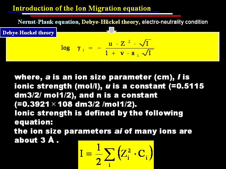
105 A3-27 NUMO-TR-04-05


106 A3-28


107 A3-29 NUMO-TR-04-05


108 A3-30


109 A3-31 NUMO-TR-04-05

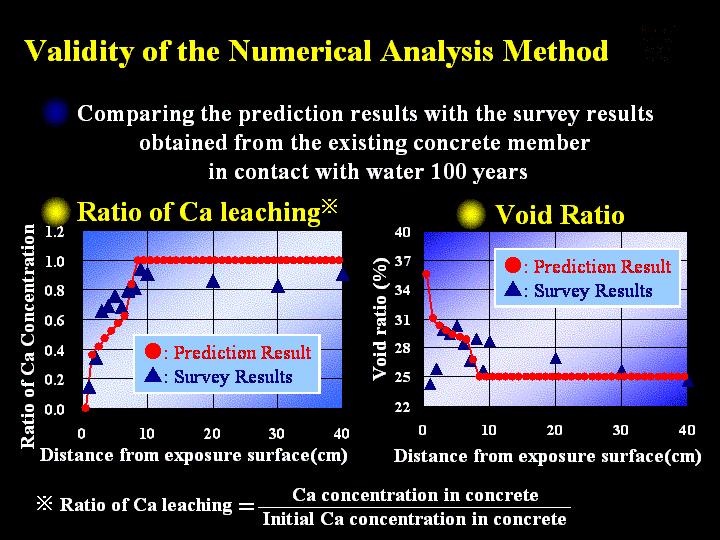
110 A3-32


111 A3-33 NUMO-TR-04-05


112 A3-34


113 A3-35 NUMO-TR-04-05


114 A3-36


115 A3-37 NUMO-TR-04-05
116 DISSOLUTION MECHANISM AND KINETICS OF SMECTITE UNDER ALKALINE CONDITIONS Tsutomu Sato 1, Masato Kuroda 2, Shingo Yokoyama 2, Masanori Tsutsui 2, Keisuke Fukushi 3, Tadao Tanaka 4 and Shinichi Nakayama 4 1 Institute of Nature and Environmental Technology, Kanazawa University, Kanazawa, Ishikawa, , Japan 2 Graduate School of Natural Science and Technology, Kanazawa University, Kanazawa, Ishikawa, , Japan 3 Research Center for Deep Geological Environments, National Institute of Advanced Industrial Science and Technology, Tsukuba, Ibaraki , Japan 4 Department of Fuel Cycle Safety Research, Japan Atomic Energy Research Institute, Tokai, Ibaraki , Japan INTRODUCTION Extensive use of cement for encapsulation, backfilling, and grouting purposes is envisaged in geological repositories of radioactive waste. Degradation of cement materials in the repositories can produce a high ph pore fluid initially ranging from ph 13.0 to The ph of fluid progressively decreases to moderately alkaline range with the formation and evolution of subsequent materials (Atkinson, 1985). The high ph pore fluids can migrate from the repository and react chemically with the host rock and bentonites which were employed to enhance repository s integrity. These chemical reactions can affect the capacity of the rocks and bentonites in retarding the migration of radionuclides. Smectite, main component of bentonite, can lose some of their desirable properties at the early stages of bentonite-cement fluid interaction. This has been a key research issue in performance assessment of radioactive waste disposal. The effect of high ph fluid on the chemical and physical behavior of smectite, especially dissolution behavior and rates is of utmost importance. A mineralogical conversion during the interaction with high ph fluids and its effect on swelling and sorption capacities have been roughly understood (for example; Johnston & Miller, 1984, Duerden, 1992, Savage et al., 1992, Eberl et al., 1993, Bauer & Berger, 1998, Amaya et al., 1999 and Sato, 2001). However, most of the previous studies have focused mainly on the mineral conversion under high ph and high temperature conditions. Only a few studies on smectite dissolution rate under different ph conditions and relatively low temperature expected in the repository have been systematically carried out In the above studies, reliable data was probably obtained because the experiments were carefully performed under the given conditions. However, as following two reasons, the experimental results are difficult to compare a priori for discussing the ph effects on the dissolution rate of smectite. Firstly, most of the authors used not an almost pure smectite but a bentonite containing other minerals such as cristobalite, quartz, calcite, feldspar, and so on. The sample studied by Cama et al. (2000) was mainly composed of an illite/smectite interstratified mineral with about 85-90% smectite. Secondly, the dissolution rates have been obtained from the different systems, i.e., flow-through (open) or batch (close) systems. In the batch system performed by many authors, the degree of saturation (i.e., deviation from equilibrium) should be changed as function of time, and then the smectite dissolution does not attain a constant rate (Oelkers et al., 2001). In this context, stirred-flow-through dissolution experiments were carried out to determine reliable dissolution rates of smectite from neutral to highly alkaline condition and to formulate the effect of ph and temperature on smectite dissolution rate. Atomic force microscopy (AFM) using fluid cell also performed to determine the reactive A3-38
117 surfaces and reliable dissolution rate in smectite dissolution and to understand mechanism of the dissolution under alkaline condition. EXPERIMENTS Flow-through system was employed in this study because the flow-through experiments allow us to measure the dissolution rate under steady state condition. Experiments were carried out using stirred-flow Teflon reactors with long cylindrical shape. To avoid ph change due to the solution-co 2 interaction, the preparation, stock and collection of the solution were performed in glove box filled with N 2 gas atmosphere. The experiments were performed for mixed NaOH-NaCl or KOH-KCl aqueous solutions with ionic strength of 0.3 M. Purified smectite (Kunipia-P provided from Kunimine Industry Co Ltd) was reacted at the phs from 8-13 and constant temperature of 30, 50 and 70 C. For each experiment, 120 mg of the sample was added to the 120 ml of the solution in the reactor. The concentrations of Al in the contacted aqueous solutions were determined by using inductively-coupled plasma mass spectroscopy (ICP-MS), and Si was determined as SiO 2 through molybdenum-blue spectrometry. The dissolution rates were calculated from the steady-state Si and Al concentrations. Adsorption of protons and hydroxyl ions with the sample was investigated by acid/base titration. The titration was performed under N 2 gas bubbling to exclude CO 2, constant ionic strength (0.3 M NaCl) and at temperatures used in the experiments (T = 30, 50 and 70ºC). Acidimetric titrations were performed until ph 4, while alkalimetric titration were conducted until ph 10. The following three setups for the dissolution experiments by AFM observations were prepared (referred here as Run X); Run I: short-term in situ batch dissolution experiment at room temperature (22 C); Run II: long-term in situ flow-through dissolution experiment at room temperature (22ºC); and Run III: long-term dissolution experiments at 50 C. The dissolution experiments were conducted under highly alkaline conditions (ph 13.3 ± 0.1) using 0.3 M NaOH solutions. For Run III, the samples mounted on mica plates were immersed and heated in 50 ml 0.3M NaOH solutions inside Teflon containers. The samples are allowed to react for a period ranging from 6 to 33 days at 50ºC and then placed inside the fluid cell of the AFM to prevent further dissolution with entrained alkaline reacting solution. The samples mounted on the mica plate were observed under AFM at 22ºC to detect changes in particle volume after the dissolution reactions. A hundred particles were observed to be statistically viable. RESULTS AND DISCUSSION In the present study, possibilities of other variables were except for ph and temperature eliminated by conducting all experiments at constant of the factors. Therefore, the observed difference in the dissolution rates should be attributed to the difference in the ph and temperature of the solution. From the rates obtained in the dissolution experiment, it is unambiguously shown that the ph strongly affects the dissolution rate under alkaline condition, and the rates increase with an increase in the ph. Fig. 1 is plot of the logarithm of the rate versus the ph of the solution. Good linear relationships are observed between ph and log rate. The rate laws were calculated by fitting the dissolution log rate to the ph value, and yielded the following equations: Rate ( mol s ) 10 a (in 30 C NaOH solution) = H Rate ( mol s ) = 10 a (in 50 C NaOH solution) H + A3-39
118 Rate ( mol s ) = 10 a (in 70 C NaOH solution) H + The dissolution rates calculated cover a range of alkaline ph. The rates become more phdependent with increasing temperature. The changes in ln rate at constant ph as a function of 1/T are shown in Fig. 2. The calculated values of E exp for smectite dissolution range from to kj mol -1. The lowest values are at near neutral ph but the rates increase with increasing ph. The changes in E exp as a function of ph are shown in Fig. 3. The variation in activation energy with ph causes rates to become increasingly sensitive to ph at elevated temperature. Above ph 8, the obtained relation between ph and activation energy is shown following equation: E exp = 6.80 ph In order to formulate the effect of ph and temperature on the dissolution rate, model of two parallel reaction paths are proposed according to Cama et al. (2002), gives Rate b + + i 1 a b H 2 ah = k1 F1 + k2 F2 ρ r 1+ b1 a + 1+ b a + H 2 H where F i is the maximum surface coverage of protons on site i, b i is a constant related to the energy of adsorption on site i and a + is the activity of protons in solution. H A ph-independent apparent activation energy for each of the reaction paths is calculated by plotting an Arrhenius plot of the rate coefficients (k' 1 and k' 2 ) at 30 C, 50 C and 70 C, which were obtained from the fitting of the experimental data to the proposed model. The apparent activation energies were determined from a best-fit of rate coefficients that were obtained by fitting the experimental results at each temperature. The following equation was obtained by fitting the whole data set into a single equation 20.4/ RT 23.5/ RT 177 e a e a / RT OH 69.7 / RT OH Rate= e e 20.4/ RT 23.5/ RT e a e a + OH OH The proposed model shows that smectite dissolution rate may be described by a rate law using activation energies being ph-independent. The dissolution mechanism can be interpreted in terms of surface complexation theory. In this study, the surface properties of smectite at different temperature, reactive surface parameters and distribution of reactive sites as a function of ph were systematically investigated. As the result of investigations, the first and second reaction sites in the above equation are Si site and Al site, respectively. Combining the above equation (the terms of effect of temperature and ph) and f( G r ) obtained from Cama et al. (2000) into the general rate law (Lasaga 1995, 1998) gives 20.4/ RT 23.5/ RT 177 e a e a / RT OH 69.7/ RT OH Rate= ( e e ) 20.4/ RT 23.5/ RT e a e a 10 ( 610 ) ( Gr 6 ) + OH RT (1 e ) In Run I, the observed reduction in smectite particle volume can be attributed solely to edge surface dissolution. Dissolution rate calculated based on the surface area defined by the ESA (observed edge surface area) is mol/m 2 sec. On the other hand, there were no detectable changes in particle volume in Run II which is already achieved a steady state for dissolution. The relatively faster dissolution in Run I was also observed at the initial stage in the flow-through dissolution experiments. The dissolution rates were therefore different between at initial and steady state conditions. In Run III, the dissolution rate was calculated based on the median values of the basal surface areas of particles. The reduction in particle volume is mainly attributed to dissolution along edge surface areas despite the formation of a + OH A3-40
.")
119 few etch pits on the basal surface. Based on the surface areas defined by the ESA, the dissolution rate was mol/m 2 sec. The rate is fairly close to that obtained from the flow-through dissolution experiment at 50 C and ph 13.3 ( mol/m 2 sec). From AFM observation, the dissolution rates derived at longer observation periods were directly comparable with the results from the flow-through dissolution experiments. Furthermore, the actual reactive sites (e.g. ESA) in the dissolution reactions were determined and used in the calculations of dissolution rate, which reflect the real dissolution rate of smectite. On the contrary, the rates obtained from flow through dissolution experiments were sufficiently reliable because of the above correspondence in the obtained dissolution rates ACKNOWLEDGEMENT This is a part of study funded by Radioactive Waste Management Funding and Research Center, Japan. log rate (mol/m 2 s) :Rate= a H :Rate= a H :Rate= a H Fig. 1 Relationship between logarithm of the dissolution rates and the ph of NaOH solution each temperature (30, 50, 70ºC). Activation Energy (kj/mol) ph E exp =6.80pH ph Fig. 3 Experimental activation energy (E exp ) for dissolution of smectite as a function of ph. ln rate(mol/m 2 ) ph12.0 ph11.0 ph10.0 ph9.0 ph /T Fig. 2 Arrenius plots of smectite dissolution rate at different ph of the solution. Basal surface area (nm 2 ) Y = -0.75X r = Reaction time (sec) ESA: mol/m 2 /sec TSA: mol/m 2 /sec Fig. 4 Changes in AFM images and basal surface area of the sample particle in the dissolution process (22 C, ph=13.3). Calculated dissolution rates based on edge surface area and total surface area also shown in this figure. A3-41
120 Experimental study on changes of bentonite mineralogy and physical properties as a result of exposure to high ph solutions Ola Karnland 1, Ulf Nilsson 1, Siv Olsson 2, Patrik Sellin 3 1 Clay Technology AB, ok@claytech.se, 2 Geochimica, Lund, 3 SKB, Stockholm INTRODUCTION AND OBJECTIVS In a repository for spent nuclear waste, it will be most practical to use concrete in many constructions, and cement for sealing rock fractures. In the Finnish ONKALO underground facility, the estimated quantity of injected cement is 3E6 kg, and in the Swedish planned KBS3 repository the corresponding figure is around 9E5 kg. The high ph in cement pore water may affect the stability of repository components, and is therefore of concern for the performance and safety assessment analyses. In a KBS3- type repository, the high ph may influence fracture minerals, the bentonite buffer, canister components, and the spent fuel in case of a canister failure. The ph evolution in the bentonite is of special interest, since it completely surrounds the fuel canisters and therefore may protect the canister and fuel. Such ph buffering capacity may be due to accessory mineral reactions, montmorillonite surface reactions and montmorillonite crystal lattice reactions. Fresh cement may raise ph to values between 13 and 14, and in matured cement materials ph is governed by portlandite (Ca(OH 2 )), which gives a ph of around Compared to ground water conditions this leads to an increase of the cation/proton activity ratio and into the stability field of Feldspars, and up to four orders of magnitude higher silica activity. Several studies have been made concerning the interaction between bentonite and cement pore-water, of which most have been batch experiments with high water/solid ratio. The present study focuses on highly compacted bentonite since e.g. ionequilibrium and transport restrictions significantly may affect possible reactions and reaction rates. The overarching objectives were to gather information concerning ph evolution in compacted bentonite, ph buffering capacity, changes in mineralogy, changes in swelling pressure, and possible specific effects of accessory minerals on the above items,. EXPERIMENTAL Commercial Wyoming bentonite from American Colloid Co. (MX-80) was used as starting material for all tests. The original material was used to produce almost pure homo-ionic montmorillonite with Na +, K +, and Ca 2+ as exchangeable cations, respectively. Tests were made with the purified and the original material. The test solutions were chosen to be 0.1, 0.3 and 1.0 M NaOH, and saturated Ca(OH) 2 solution. The corresponding ph values as calculated by PHREEQC are 12.9, 13.3, 13.7 for the NaOH solutions, 12.4 for the Ca(OH) 2 solution. The samples had a 35 mm diameter, and a 55 mm height. The proposed KBS3 buffer density of 2000 kg/m 3 at full water saturation was aimed at in all tests. A3-42
 was slightly over-compacted compared to the intended density and placed in the cylindrical sample holders made of titanium and PEEK (Figure 1).")
121 A-side ph measured 0.5 L NaCl load cell sample 0.5 L NaOH ph controlled B-side Figure 1 Schematic drawing and photo of a sample holder. Air dry test material (water ratio ~10%) was slightly over-compacted compared to the intended density and placed in the cylindrical sample holders made of titanium and PEEK (Figure 1). The samples were water saturated by slowly circulating 0.5 L deionized water behind the filter by means of a peristaltic pump. After reaching pressure equilibrium, the water was changed to the predefined chloride solutions, and after reaching new pressure equilibrium, the chloride solutions at the bottom side (B) were changed to 0.5 L hydroxide solutions (high ph), and the 0.5 L isotonic chloride solution were left on the upper side (A). In a few tests the same solution was used on both sides of the samples and successively changed on both sides. At test termination the solutions were disconnected and the samples were quickly removed, split, and characterized with respect to physical and mineralogical properties. MEASUREMENTS AND ANALYSES The temperature and swelling pressure were automatically measured every half hour, and ph was measured virtually daily in the low ph solutions, and weekly in the high ph solutions. The type of exchangeable cations was determined by exchange with ammonium ions, and the cation exchange capacity was determined by exchange with copper(ii) triethylenetetramine. XRD scans were made both of random powders and as oriented samples. Mineralogical quantification was made by use of the Siroquant software based on Rietveld technique. Element analyses were made by use of ICP/AES for both the clay and the test solutions. Anions were analysed by use of ion chromatography (IC). Scanning electron microscopy and microanalyses (EDX) were used to study microstructure and mineral distribution. A3-43
122 RESULTS The measurements and analyses were fully carried out for the 12 separate tests. Significant reductions in swelling pressure were found for the samples contacted to high concentrations of sodium chloride and hydroxide solutions. A major difference was, though, that the chloride solutions gave a fast drop to a new stable pressure value, while contact to the hydroxide solution led to a continuous lowering of the swelling pressure. Figure 2 (left) shows the pressure response from one sample successively exposed to pure water, 1.0 M NaCl, 1.0 M NaOH, 1.0 M NaCl, and finally pure water. A significant continuous swelling pressure reduction was also observed for all samples exposed to 0.3 M NaOH solutions. However, no swelling pressure change was noticed in the samples exposed to 0.1 M NaOH or to saturated Ca(OH) 2 solution. Swelling Pressure, kpa NaCl NaOH 1.0 M NaCl H 2 O Time, days Swelling Pressure, kpa NaCl MX-80 NaOH 0.3 M 1.0 M 0.1 M Time, days Figure 2. Left: Pressure response from a MX-80 sample successively exposed to pure water, 1.0 M NaCl, 1.0 M NaOH, 1.0 M NaCl, and finally pure water. Right: Swelling pressure evolution in three MX-80 samples. All samples were initially saturated with pure water, subsequently exposed to the chloride solutions (5 days), and finally to the hydroxide solutions on one side (60 days). A ph increase in the NaCl solutions was measured in the four tests exposed to 1.0 M and 0.3 M solutions. Logically, the increase came earlier and was more pronounced in the tests with the highest concentration. A systematic release of silica was found in these tests (Table 1). No ph increase was measured after 45 days in tests with 0.1 M solutions, and neither after an exposure time of 110 days in the four tests with saturated Ca(OH) 2 solutions.. Table 1. ICP/AES analyses of solutions from tests with MX-80 exposed to NaOH solutions. Concentrations are expressed in mm. Sample ph Al Ca Mg K Si Ti NaCl side 21 n A3-44
123 NaOH side A significant increase in CEC was noticed for all samples exposed to the NaOH solutions. The increase was significant on both sides of the samples except for the NaCl side of the MX-Na sample exposed to the 0.1 M solutions. No significant change in CEC was measured in the samples exposed only to NaCl solutions (sample 31 and 32), or to the four samples exposed to the M Ca(OH) 2 solutions. No neoformation of minerals was indicated in any of the MX-Na samples. A small amount of soft gel material was found outside of the filter on the low ph side in one test. The ICP/AES element analyses show that the silica/aluminium ratio decreased significantly in samples exposed to the NaOH solutions, and an Si/Al gradient from the NaOH to NaCl solutions side. DISCUSSION AND CONCLUSIONS It is obvious from the present results that a ph plume may pass through highly compacted bentonite at a sufficiently high ph gradient. It is also obvious that it is strongly affected by reactions between the hydroxide and bentonite minerals, and the effective transport is not well described by diffusion parameters only. In the present experiments the bentonite swelling pressure was strongly reduced by exposure to 0.3 (ph 13.3) and 1.0 M (ph 13.7) NaOH solutions. The reduction seems to be due to an instant osmotic effect, and to a continuous dissolution of silica minerals leading to mass loss. The decrease rate due to dissolution was reduced after a relatively short time, and a subsequent almost constant decrease rate was observed. The initial decrease rate is likely governed by dissolution of cristobalite, and the latter due to dissolution of montmorillonite and quartz when cristobalite is depleted. A significant increase in CEC was observed in samples exposed to the NaOH solutions. The structural formulas of the exposed montmorillonite were calculated based on the ICP/AES and CEC data, and show a significant release of silicon from the montmorillonite structure. This incongruent dissolution leads to a charge increase in the tetrahedral layers and a first step towards beidellite. This observed moderate charge increase can be seen as a minor problem with respect to the buffer functions. However, the physical properties of the clay will change dramatically if this reaction continues until a high charge mineral is formed, or a general breakdown of the structure takes place. The silicon release rate from montmorillonite in this specific geometry was determined to be 1.6E-9 g*g -1 clay*s -1 for the 1.0 M NaOH solutions conditions and 5E- 10 g*g -1 clay*s -1 for the 0.3 M conditions. No effect on swelling pressure was found in the samples exposed to 0.1 M NaOH (ph 12.9) and saturated Ca(OH) 2 solutions (ph 12.4). No mineralogical/chemical effect except ion exchange from sodium to calcium was found in the samples exposed to the Ca(OH) 2 solution. A3-45
124 The similar pressure response of bentonite exposed to NaCl and NaOH solutions indicate that ion-equilibrium is established between the external hydroxide solutions and the clay pore-water, which then leads to reduced ph inside the clay. This effect increases theoretically with bentonite density and with decreasing ph in the external solution (groundwater). The chemical reactions between the introduced hydroxide and the clay will therefore be less intense, more localized, and lead to lower final ph. At moderately high ph, the combined effect leads to a large calculated difference between batch experiments and experiments with highly compacted bentonite with respect to mineralogical alteration rate. Ion equilibrium conditions may consequently explain the minimal physico-chemical changes in the samples exposed to 0.1 M NaOH and saturated Ca(OH) 2 solutions. Acknowledgments The authors wish to acknowledge that this paper is a result of work funded by the Swedish Nuclear Fuel and Waste Management Company (SKB) and the European Commission. A3-46
125 EFFECTS OF SALINE ALKALINE ATTACK ON BENTONITE AND CRUSHED ROCK EXPERIMENTAL AND MODELLING STUDIES ECOCLAY II Ulla Vuorinen*, Ari Luukkonen#, Jarmo Lehikoinen*, *VTT Processes, #VTT Building and Transport, FIN VTT, Finland, Heini Ervanne, Department of Chemistry, Laboratory of Radiochemistry, FIN University of Helsinki, Finland INTRODUCTION The use of concrete and shot crete in constructing a deep disposal vault for spent fuel has raised questions about the effects of an alkaline perturbation on the buffer materials used and the possible consequences to the safety of the final disposal system. In order to facilitate an assessment of the propagation of an alkaline plume in the bentonite buffer and to detect alterations brought about by such a plume laboratory studies were initiated within the European 5th frame work project ECOCLAY II. EXPERIMENTAL Six flow-through cylinders, each containing site specific crushed rock (<1.5 mm) from Olkiluoto, Finland in one half, and compacted bentonite (2 000kg/m 3 ) (commercial Wyoming bentonite MX- 80) in the other half. Thecylinders were subjected to an attack of a slow flow of solution. The solution rate used was 2.5mL/day, comparable to groundwater flow rate in deep disposal conditions. Three different solutions were used, saline alkaline (ph=12.5), saline (ph=8.3) and fresh (ph=8.8) solutions, one solution for each cylinder in the two sets of cylinders. Both cylinder sets were started at the same time and ran simultaneously. The experiments were performed at ambient temperature inside a glove-box with nitrogen atmosphere in order to avoid disturbances of atmospheric CO 2 on the alkaline system. Solution samples were collected at the out-flow end for analyses and measurement of ph. The first set of three cylinders were dismantled after about a year and the other set of three after about 1.5 years. The solids, crushed rock and compacted bentonite, were sectioned and analysed for mineral alterations. Bentonite pore water was analysed in several bentonite specimen sampled along the cylinder length, as well as the amount of exchangeable cations (Na, Ca, K, Mg). Batch experiments were also conducted using the same solid materials as in the flow-through cylinder experiments. The solids were treated separately with three alkaline solutions (fresh alkaline ph 12.5, saline alkaline ph 12.5 and saline hyper alkaline ph 13.5). The solid/solution ratio used was 1/10 and the equilibration periods 1 week, 1 month, 6 months, 1.5 years. The batch experiments were also conducted in nitrogen atmosphere at ambient temperature. After completion of each period the phases were separated by centrifugation and filtration. Both the solutions and solids were analysed. The mineral alterations were more prominent in the batch experiments than in the flowthrough experiments. The solution analysis results were the basis in the modelling (inverse) of the mineral reactions occurring. RESULTS AND DISCUSSION Flow-through experiments The saline alkaline solution affected bentonite throughout the entire column to some extent as all the determined exchangeable cation capacities (CEC) either increased or decreased when compared A3-47
126 to the initial MX-80 bentonite values (Figure 1). There was a clear decreasing trend in the column with more prominent changes at the in-flow end. However, the ph values in the bentonite pore water samples (Figure 2) supported alkaline changes only near the interface with a clear decreasing trend towards the cylinder end. The out-flow solution had reached a ph value around 9.5 by the end of the experiment and showed an increasing trend (Figure 3). If the alkaline ph was to keep its trend the estimated time needed for the out-flow solution ph value to reach a value around 11 would be about 6 years and to reach the initial value of 12.5 would take about 10 years. In the saline and fresh experiments the out-flow solution ph values levelled off at around 9.5 and about 8, respectively. 0.8 Na 0.20 Ca [meq/g of bentonite] K 0.06 Mg [meq/g of bentonite] A1 1 B1 2 B2 3 C1 4 D1 5 E1 6 F1 7 F1 8 F Figure 1. Measured CEC (cation exchange capacity) values (meq/g of bentonite) for the four elements in the saline alkaline case. The red bar on the left shows the initial CEC of MX-80. The text box in the figure indicates the bentonite samples along the flow-through column(a=in-flow end, F=outflow end, 1=interfac specimene, 2=below interface specimen) in each category OL-SA ALL-MR initial ALL-MR I ALL-MR II OL-SA initial OL-SA I OL-SA II OL-SS initial OL-SS I OL-SS II ph d 560 d ph A11 A2 2 B1 3 B2 4 D15 D2 6 F1 7 Figure 2. Bentonite pore water ph in the saline alkaline experiment for both the 360 d and 560 d cylinder ml Figure 3. ph values of the out-flow solutions during the experiment versus the amount of solution (ml) passed through the cylinders. In green the saline alkaline values (I=360d, II=560d). A3-48
127 The initial saline solutions did not contain K +, Mg 2+, SO 4 2-, or Si(aq). The levels of K + were quite similar in both saline cylinder experiments, both in the determined exchangeable cations and in the out-flow solutions indicating that interactions with bentonite were well reflected in the out-flow solution composition. This was also true for SO 4 2- and Si(aq), based on pore water and out-flow solution results. In the case of exchangeable Mg 2+ the amount left in the bentonite samples of the saline alkaline case was less than in the saline case, but this was not reflected in the Mg 2+ contents of the out-flow solutions even if the pore water analysis showed depletion of Mg 2+. This indicates that Mg 2+ remained to some extent inside the alkaline column undergoing possible reactions. The depletion of Ca 2+ in the pore water and the decreasing trend in the out-flow solutions in the saline alkaline case, which was contrary to the increasing trends in the other two experiments, supports the retention of Ca 2+ in the column and possible undergoing reactions as well. An increase in the CEC of bentonite in all alkaline experiments and also in the saline flow-through experiment was observed. The increase was more significant in the batch experiments. The cause of the increase is not quite clear at this point, especially in the saline experiment, but in the alkaline cases partial alteration of montmorillonite to beidellite can be an explanation as indicated by the mineral analyses. Batch experiments As expected greater changes to the initial solution ph values occurred in the bentonite batches (Table 1), nevertheless, the ph decreased somewhat in all cases. Table 1. The measure ph values of the contacting solutions after phase separation. Rock MX-80 duration fresh saline saline hyper fresh saline saline hyper days alkaline alkaline alkaline alkaline alkaline alkaline The most prominent changes in the solution chemistries were met in the saline hyper alkaline experiments (Table 2), but the trends were rather similar in the other solutions as well; - Ca content decreases, Si content increases, except in the fresh alkaline MX-80 solution which gave the highest concentration after 6d and thereafter decreased (gel-formation). - More Al appears in the rock solutions than MX-80 solutions A3-49
128 Table 2. The analysis results of the contacting solutions. The initial solution composition is given in the yellow row. In the flow-through experiments (Table 4) minimal detectable changes in the crushed rock occurred. The reactivity of bentonite is much higher than that of crushed rock. In the saline alkaline flowduration Na Ca K Mg Al Si Fe Cl SO 4 EC in mg/l mg/l mg/l mg/l mg/l mg/l mg/l mg/l mg/l (ms/m) days <2 < < < Bentonite < < < < < < < Rock < < < < < < < Mineralogical summary Crushed rock alterations The crushed rock was prepared from Olkiluoto mica gneiss (75 wt%), granite pegmatite (20 wt%) and tonalite (5 wt%). The rock material was crushed to grain sizes <1.5 mm. All materials, including the fine fractions were mixed together. The mineralogy of the mixture is given in Table 3. Table 3. Estimated initial mineral composition (in wt%) for crushed rock used in the experiments. Mineral wt% Mineral wt% Mineral wt% Quartz 23.2 Sillimanite 5.4 Zircon 0.2 Oligoclase 19.2 Muscovite/Sericite 2.9 Carbonate 0.1 Microcline 17.1 Hornblende 1.6 Apatite 0.1 Biotite 20.1 Chlorite 1.2 Sulphides 0.3 Cordierite 8.3 Epidote/Saussurite 0.3 In the batch experiments (Table 4) microcline was found to react. A corresponding increase in sericite was interpreted from the hyperalkaline case. The dissolution of oligoclase was probable in all experiments. In the hyperalkaline experiment the low Ca 2+ solute concentration promoted dissolution of the anorthite part of oligoclase, and possibly minor production of saussurite. In the fresh alkaline experiment the albite part of oligoclase was believed to dissolve more readily. It seems that the high Na + solute concentrations in the saline experiments inhibited dissolution of albite. The saline experiments also indicated dissolution of hornblende and cordierite. It is suggested that a significant part of hornblende was altered to chlorite, and Mg 2+ needed for this conversion was partially produced from the decomposition of cordierite. The final water results of the batch experiments indicated a sink for Na +. In the saline experiments small precipitation of halite was a partial sink. It is believed that the newly-formed surface edge sites of the recently crushed rock were a distinct Na + -sink as well. The overall mass transfer in the crushed rock batch experiments was low. However, as a response to the small drops in ph, the batches produced minute amounts of CSH-gel. This gel gave a sink for Ca 2+. A3-50
129 through experiment similar changes to those in the saline alkaline batch experiment were assumed. Interpretations were, however, subject to ambiguities because of the compositional variations in the crushed mixture. In the near-neutral-ph experiments the crushed silicates were expected to be nonreactive. Small amounts of precipitated halite were observed in the saline flow-through experiments. It was also assumed that the fresh surfaces of crushed minerals were potential for Na + adsorption. Table 4. Summary of the crushed rock mineralogical observations interpreted from the batch and flow-through cell experiments. + increase in final bentonite, decrease in final bentonite, () inferred but not observed. Batch Experiments Flow-through Experiments Fresh Saline Saline. Fresh Saline Saline Alkaline Alkaline Hyperalk Alkaline Hornblende ( ) Chlorite (+) (+) (+) (+) Cordierite Microcline Sericite Oligoclase Na-part (albite) Ca-part (anorthite) Saussurite (+) + (+) Halite CSH-gel (Tobermorite?) NaX MX-80 alterations In the batch experiments (Table 5) the initial Na x -montmorillonite was found to alter partially to Na x -beidellite. The degree of conversion was related to the Na/Ca ratio of the initial solution and ph. The long-term (e.g. 540 days) hyperalkaline attack produced smectite that indicated good resemblance to crystallography of Na x -beidellite. The main sink for Na + was apparently the cation exchange sites of the altered smectite. However, according to Hong and Glasser (1999, 2002) also CSH gel is a Na + -sink especially in high Na + solute conditions. The CEC studies with altered solids indicated an increase in the exchange sites as a result of the alterations. The other main cations were released from bentonite. K + remained in the final solution, while Mg 2+ assumably adsorbed or precipitated into CSH gel (cf. Taubald et al. 2000). The main sink for Ca 2+ was CSH gel and to a minor extent calcite. Especially in the hyperalkaline case quartz dissolved partially and albite almost completely. Significant amounts of halite precipitated in the saline batch experiments. In the flow-through cylinder experiments (Table 5) the changes in smectite were found to be diverse. The dilute near-neutral-ph fresh water injection resulted in complexly fluctuating cation distributions in bentonite. The constant release of Na + and silica from bentonite seems to have caused interlayer deficiencies in montmorillonite. Due to the relatively low Na/Ca ratio, the nearneutral-ph saline water caused smectite to transform towards Ca x -montmorillonite. The saline alkaline water interaction indicated comparable smectite alteration to the equivalent batch experiment. The near-neutral-ph experiments released Na + while the alkaline experiment adsorbed Na + into the cation exchange sites. In the near-neutral-ph saline experiment, the released Mg 2+ was left to final solution while in the saline alkaline experiment Mg 2+ was apparently caught by CSH gel. In all experiments, the sink for Ca 2+ was either Ca x -montmorillonite or CSH gel. Small amounts of calcite were precipitated in all cylinders. In the near-neutral-ph experiments no formation of CSH A3-51
130 gel occurred, and apparently no significant increases in the CEC. In the saline experiments a small amount of halite precipitated in bentonite. Table 5. Summary of the bentonite mineralogical observations interpreted from the batch and flowthrough cell experiments. + increase in final bentonite, decrease in final bentonite, () inferred but not observed. Batch Experiments Flow-through Experiments Fresh Saline Saline. Fresh Saline Saline Alkaline Alkaline Hyperalk Alkaline Na x -Montmorillonite Ca x -Montmorillonite + Na x -Beidellite Deficient Montmorillonite + Gypsum Albite ( ) Quartz ( ) ( ) ( ) Halite Calcite CSH-gel (Tobermorite?) NaX KX CaX 2 ++ MgX 2 CEC increase Modelling A simple thermodynamic forward model developed for montmorillonite was applied to describe the uptake of sodium and calcium on MX-80 bentonite reacted with saline hyper-alkaline solution. The experimental findings were adequately explained by the model, provided that sorption of calcium takes place predominantly by way of precipitation of calcium-bearing mineral phases. Forward modelling considered quartz, calcite, microcline and albite as primary accessory minerals of MX-80. In the hyper-alkaline modelling, the minor solid assemblage of bentonite was completely destroyed upon reacting with the solution, which resulted in the formation of zeolite and silicate phases. At the point of modelling, the mineralogical interpretation of the secondary solid phases was fraught with uncertainties, however. The inverse modelling results for MX-80 and crushed rock replicated most mineralogical alteration processes identified in the mineralogical studies. In MX-80 the important processes were the partial conversion of smectite (from Na x -montmorillonite to Na x -beidellite), complete dissolution of albite and partial dissolution of quartz. Laboratory observations indicated significant production of CSHgel and that was interpreted analogous to structurally defect 14Å-tobermorite. In the crushed rock experiments the main alteration processes were partial dissolution of microcline and hornblende. Since the geological conditions otherwise are similar to the bentonite experiments, CSH-gel was assumed to form accordingly. Evidently, however, the reaction rates in the crushed rock experiments are lower due to the overall smaller reactive surface area than in the bentonite batches. In the inverse modelling of the hyperalkaline experiments significant difficulties were met with charge balancing the analytical results. Uncertainties in the concentrations of Na +, Cl - and OH - were A3-52
131 reflected as difficulties to adjust the cation exchange to the correct level in both MX-80 and crushed rock batch experiments. Acknowledgements The authors wish to acknowledge the European Commission and Posiva Oy for funding the work presented here, which was carried out under a cost-sharing contract with the European Atomic Energy Community (EURATOM) within specific programme on Nuclear Energy ( ), Key Action on Nuclear Fission, Area: Safety of the Fuel Cycle Waste and Spent Fuel Management and Disposal. REFERENCES Hong, S.-Y. and Glasser, F.P., Alkali binding in cement pastes. Part I. The C-S-H phase. Cement and Concrete Research 29, Hong, S.-Y. and Glasser, F.P., Alkali sorption by C-S-H and C-A-S-H gels. Part II. Role of alumina. Cement and Concrete Research 32, Muurinen, A. and Lehikoinen, J Porewater chemistry in compacted bentonite. Helsinki, Finland, Posiva Oy, Posiva 99-20, 46 p. Müller-Vonmoos, M and Kahr, G Mineralogische Untersuchungen von Wyoming Bentonit MX-80 und Montigel. Baden, Switzerland, NAGRA, Technisher Bericht 83-12, 15 p.+app. 13 p. Taubald, H., Bauer, A., Schäfer, T., Geckeis, H., Satir, M. and Kim, J.I., Experimental investigation of the effect of high-ph solutions on the Opalinus shale and the Hammerschmiede smectite. Clay Minerals 35, Vuorinen, U., Lehikoinen, J., Luukkonen, A. and Ervanne, H Effects of salinity and high ph in crushed rock and bentonite experimental work and modelling in 2001 and Olkiluoto, Finland, Posiva Oy, Working Report , 33 p. A3-53
132 Experimental study on dissolution of montmorillonite in compacted sandbentonite mixture under Na-Cl-OH pore-water conditions Tetsuji Yamaguchi 1, Yoshifumi Sakamoto 1, Masanobu Akai 1, Mayumi Takazawa 1 Tadao Tanaka 1, Shinichi Nakayama 1, Tsutomu Sato 2 1 Department of Fuel Cycle Safety Research, JAERI, Tokai, Ibaraki Japan 2 Institute of Nature and Environmental Technology, Kanazawa University, Kanazawa, Ishikawa , Japan INTRODUCTION Highly alkaline environments induced by cementitious materials in radioactive waste repositories are likely to alter montmorillonite, the main constituent of bentonite buffer materials, and are likely to cause the physical and/or chemical properties of the buffer materials to deteriorate. We focus our experimental efforts on predicting long-term variations in permeability of compacted sand-bentonite mixture because the variations induce major uncertainties in the radionuclide migration analysis and have not been quantitatively understood. The dissolution rate of montmorillonite and the diffusivity of hydroxide ions in the compacted sand-bentonite mixtures are essential parameters, which quantify the effects of alteration caused by the alkaline environments on the permeability of a bentonite buffer. There are not a few studies on the dissolution rates of clays in near neutral to alkaline solutions (Bauer et al., 1998; Bauer and Berger, 1998; Cama et al., 2000; Huertas et al., 2001; Sato et al. 2002). In these studies, the rates were obtained for far from equilibrium conditions, where the solid/solution ratio employed in their experiments is much lower than the disposal conditions. It is of concern if the rates are straightforward applicable to predict alteration of compacted bentonite under disposal conditions. For this reason, we have performed experiments to acquire quantitative data on the rate of dissolution of montmorillonite and diffusivity of the alkaline source in compacted, cylindrical bentonite samples under highly alkaline, saline groundwater conditions. This experimental configuration was employed because it reflects repository conditions such as the use of compacted bentonite and saline groundwater that is nearly saturated with respect to silicon and aluminum. EXPERIMENTS The dissolution rate of montmorillonite was obtained through a time-dependent variation in the quantity of montmorillonite in sand-bentonite mixtures. The mixtures of granules of Na-type bentonite (Kunigel V1, [Ito et al., 1993]) and silica sand of two different granule sizes ( mm: SiO %, mm: SiO % [Suzuki & Fujita, 1999]) were compacted to cylindrical specimens of 20 mm in diameter and 10 mm in thickness. The mixture ratio of the bentonite and silica sands was 70:15:15 in dry weight. The density of the specimens was 1.6 Mg m -3. Alteration experiments using compacted specimens require much longer time periods than Si- and Al-saturated NaOH solution Teflon container Specimen holder Specimen: Compacted sandbentonite mixture; 20 mmφ x 10 mmt 1.6 Mg m -3 Fig.1 Schematic drawing of the experimental configuration for the alteration experiment. A3-54
133 those using granules. Temperatures were selected to be 50 o C to 170 o C, and ph values were 13.0 to 14.0 to observe montmorillonite dissolution over a reasonable time period. The results will be extrapolated to repository conditions. A specimen set in the holder in a Teflon container, schematically shown in Fig. 1, was contacted with 0.08 dm 3 of ph-adjusted, simulated alkaline, saline groundwater. The simulated groundwater was prepared by equilibrating NaCl-NaOH mixed solutions of the Na concentration of 1 M with bentonite granules under the same temperature (50 to 170 o C) as those employed in the alteration runs for the equilibration period of 4 to 8 weeks. The container assembly (Fig. 1) was placed in a sealed stainless steel container and kept at desired temperatures in ovens. Each of the assembly was taken from the oven at the fixed sampling time and the compacted mixture specimen was removed from the holder, freeze-dried at 110 o C, and the amount of montmorillonite that remained was determined by the methylene-blue adsorption titration method. The reacted solid was analyzed by X-ray powder diffraction (XRD). The concentrations of Al and Ca in the contacted aqueous solutions were determined by using inductively-coupled plasma mass spectroscopy (ICP-MS), and Si was determined as SiO 2 through molybdenum-yellow spectrometry. The diffusivity is the rate of spreading of the alkaline plume in the sand-bentonite mixtures, and it also gives some indication as to whether the dissolution of montmorillonite or the transport of hydroxide ions limits the alteration of bentonite. For this reason, the two phenomena, alteration of bentonite and diffusion of hydroxide ions in bentonite, have to be quantified separately. The diffusivity of hydroxide ions in compacted sand-bentonite mixtures was obtained by the through-diffusion method using an polysulphon diffusion cell as shown in Figure. 2. The specimens of compacted sand-bentonite mixtures, which are the same in size and in mineral composition as those used in the alteration experiment, were employed in the hydroxide ion diffusion experiment. The water in one of the reservoirs (referred to as high-ph reservoir ) was replaced with simulated cementitious water, and the other (referred to as low-ph reservoir ) with simulated fresh-type groundwater. The experimental runs were conducted in the temperature range 10 to 90 o C. The throughdiffusion runs were conducted under the ambient atmospheric condition. At 7-day intervals, the ph of the aqueous solutions in the two reservoirs was measured. Butyl rubber packing Filter holder Butyl rubber O-ring High-pH reservoir: simulated cementitious water; [OH - ] = 0.5 M Compacted sandbentonite mixture; 20 mmφ x 10 mmt 1.6 Mg m -3 Sintered SUS filter; 1 mmt Low-pH reservoir: simulated fresh-type groundwater; [OH - ] = 1x10⁻⁵ M Fig. 2 Schematic drawing of the through diffusion cell used in the hydroxide ion diffusion experiment. RESULTS AND DISCUSSION The amount of montmorillonite in the compacted sand-bentonite mixtures decreased in a few days to several months under the employed conditions of ph and temperature, as seen in Fig. 3. X-ray diffraction patterns of sand-bentonite mixtures indicated the decrease of montmorillonite. Crystalline silica also dissolved, and a secondary mineral, analcime A3-55
134 (NaAlSi 2 O 6 ), was formed. The linear decrease in the amount of montmorillonite with time clearly differs from the widely-accepted exponential decrease in dissolution of 0.8 :90 minerals (e.g., Stumm & Morgan, 1996). : The linear decrease can be expressed as :170 W ( t) = W (0) RAt, where W (t) denotes 0.4 the density of montmorillonite (Mg of montmorillonite/m of sand-bentonite 0.0 mixture), W (0) the initial density (1.758 Mg/3.14 m 3 = 0.56 Mg m -3 ), R A (Mg m Time (day) s -1 ) the rate of density decrease and t (s) Fig. 3 Dissolution curves of montmorillonite in the time after the contact with the compacted sand-bentonite mixture as a simulated groundwater. The R A is a function of time at [NaOH] ~0.3 M. -5 function of ph and temperature as shown :50 in Fig. 4, and can be expressed as R A = 0.8 [OH - ] 1.4 e /RT -6 :90 (1) where R the gas constant (8.314 J mol -1 :130-7 :170 K -1 ). The activation energy of 48±10 kj -8 mol -1 is close to that of formation of analcime, kj mol -1-9 (Kim, 2001), and higher than that of dissolution of -10 montmorillonite, 30 kj mol (Huertas et lo g O H log [OH al., 2001). The alteration rates estimated - ](M) - by Eq (1) were compared with previous Fig. 4 Dependence of the montmorillonite dissolution rate, R data from batch dissolution experiments A (Mg m -3 s -1 ) on temperature and on [OH - ]. for smectite obtained in hyperalkaline solutions at 35 o C and 80 o C (Bauer and Berger, 1998) in Fig. 5. The dissolution rates of montmorillonite obtained for compacted sand-bentonite mixtures in [Mg-montmorillonite / m 3 -bentonite / s] were converted to [mol-si / m 2 / s] using the SiO 2 content in the montmorillonite of 61.3 % (Ito et al., 1993) and the specific surface area of 2.7x10 4 m 2 kg -1 (Shibutani et al., 1999). The dissolution rates of montmorillonite obtained for compacted sand-bentonite mixture are lower than those in the batch dissolution experiments by one order of magnitude or more. The dependence on concentration of OH - is higher for compacted sand-bentonite mixture than that in the batch dissolution experiments. The dissolution of montmorillonite in compacted sand-bentonite mixture is likely to result from some different mechanisms from that occurring in the farfrom-equilibrium batch dissolution experiments. In the hydroxide ion diffusion experiments, it took a few tens of days for the ions to diffuse through the 10 mm-thick compacted sand-bentonite mixture disks. Hydroxide ions were mainly consumed by dissolution of soluble silicate minerals during the delay. After the delay, the activity in the low-ph reservoirs began increasing. The increasing rate becomes Monmorillonite density (Mg m -3 ) lo g R a log RA(Mg m -3 s -1 ) A3-56
135 close to the decreasing rate of the activity in the high-ph reservoirs, and when the two values of the rate were identical, the steady state flux of hydroxide ions was established in the specimens. The diffusivity was calculated by using the identical values of the rate. The obtained D e values were (3.9±0.6)x10-11 m 2 s -1 at 10 o C, (4.6±2.3)x10-11 m 2 s -1 at 20 o C, (1.1±0.4)x10-10 m 2 s -1 at 30 o C, (8.9±2.2)x10-11 m 2 s -1 at 40 o C, ( )x10-10 m 2 s -1 at 50 o C, (1.8±0.7)x10-10 m 2 s -1 at 70 o C and ( )x10-10 m 2 s -1 at 90 o C, which are summarized in Fig. 6. The dependence of D e on temperature follows the Arrhenius equation of D e = exp( /RT). The diffusivity of ions in compacted bentonite materials is known to depend strongly on their bulk density, ρ (Mg m -3 ), and to be proportional to e -5.4ρ for I - (Mihara et al., 1999) which is analogous monovalent anion to OH -. The effective diffusivity of hydroxide ion in compacted bentonite materials can be expressed as a function of the temperature and the bulk density as D e = exp( /rt 5.4ρ) (2) log dissolution rate (mol-si m -2 s -1 ) Bauer, 80 Bauer, 35 Eq (1), 80 Eq (1), log [OH - ] (M) Fig. 5 Comparison between dissolution rates of montmorillonite obtained in this study and those obtained by Bauer and Berger (1998). ln D e (m 2 s -1 ) /T (K -1 ) Fig. 6 Effective diffusivity, D e (m 2 s -1 ), of hydroxide ion in compacted sand-bentonite mixture at the temperature of o C. CONCLUSIONS Dissolution of montmorillonite and diffusion of hydroxide ions in compacted sand-bentonite mixtures were measured under the simulated alkaline groundwater environments. Dissolution of montmorillonite followed the linear dependence on time under the employed experimental conditions of ph 13 to 14 and temperatures of 50 to 170 o C. The slope gives the dissolution rate, R A. The dissolution rate is a function of ph and temperature (K), and expressed as R A = 0.8[OH - ] 1.4 exp(-48000/rt), where R is the gas constant. The effective diffusivity was found to be in the order of to m 2 /s at 10 to 90 o C and expressed as D e = exp ( /RT 5.4ρ). These equations will be provided for the long-term prediction on the permeability of a bentonite buffer. The dissolution rates we obtained in this study are smaller than previous data which were obtained by far-from-equilibrium batch dissolution experiments. Dissolution mechanisms under high solid/solution ratio and near-equilibrium, A3-57
136 which is representative of the waste repository, is required to be understood to provide reliable data for the long-term prediction of the bentonite buffer performance. ACKNOWLEDGEMENT This is a part of study funded by the Japanese Ministry of Economy, Trade and Industry. REFERENCES Bauer, A., Berger G., Kaolinite and smectite dissolution in high molar KOH solutions at 35 o C and 80 o C. Appl. Geochem., 13, Bauer, A., Velde, B., Berger G., Kaolinite transformation in high molar KOH solutions. Appl. Geochem., 13, Cama, J., Ganor, J, Ayora, C., Lasaga, C. A., Smectite dissolution kinetics at 80 o C and ph 8.8. Geochim. Cosmochim. Acta, 64, Huertas, F. J., Caballero, E., Jiménez de Cisneros, C., Huertas, F., Linares, J., Kinetics of montmorillonite dissolution in granitic solutions. Appl. Geochem. 16, Ito, M., Okamoto, M., Shibata, M., Sasaki, Y., Danhara, T., Suzuki, K., Watanabe, T., Mineral composition analysis of bentonite. PNC TN , Power Reactor and Nuclear Fuel Develop Corporation (in Japanese). Kim, S.-Y., Experimental investigations of the effect of alkali fluids on montmorillonite, albite and quartz. JNC TN , Japan Nuclear Fuel Cycle Development Institute (in Japanese). Mihara, M, Ito, M., Kato, H. and Ueta, S., Effective diffusion coefficients of HTO, Cs and I in compacted Ca-bentonite. JNC-TN , Japan Nuclear Fuel Cycle Development Institute (in Japanese). Sato, T., Kuroda, M., Yokoyama, S., Fukushi, K., Nakayama, S Effect of ph on smectite dissolution rates under alkaline conditions, Proc. Int. Conf. Clays in Natural and Engineered Barriers for Radioactive Waste Confinement. Shibutani, T., Kohara, Y., Oda, C., Kubota, M., Kuno, Y. and Shibata, M Physico- Chemical Characteristics of Purified Na-Smectite and Protonation/Deprotonation Behavior of Smectite Surface in NaCl Media. JNC TN , Japan Nuclear Fuel Cycle Development Institute (in Japanese). Suzuki, H., Fujita. T., Swelling characteristics of buffer material, JNC TN , Japan Nuclear Fuel Cycle Development Institute (in Japanese). Stumm, W., Morgan, J. J., Aquatic Chemistry Chemical Equilibria and Rates in Natural Waters, 3rd Ed., Wiley Interscience, New York. A3-58
137 Modeling of variation in permeability of compacted bentonite with alkaline fluid for long-term safety assessment of geological disposal system. Mayumi Takazawa, Tetsuji Yamaguchi, Yoshifumi Sakamoto Masanobu Akai, Tadao Tanaka, Shinichi Nakayama Department of Fuel Cycle Safety Research, Japan Atomic Energy Research Institute, Tokai, Ibaraki, , Japan INTRODUCTION Uncertainties should be quantitatively assessed in a long-term assessment of radioactive waste disposal. We focus our experimental efforts on parameters that induce major uncertainties in the radionuclide migration analysis and that have not been quantitatively understood. Alteration of the bentonite buffer material by highly alkaline environments induced by cementitious materials used in geological disposal facilities is a prioritized study. The highly alkaline environments may alter montmorillonite, the main constituent of bentonite buffer materials, and are likely to cause the physical and/or chemical properties of the buffer materials to deteriorate. Mathematical models have been developed to predict long-term alteration of bentonite such as permeability (1). However, the relationship between changes in the mineralogical composition of bentonite and variations in its permeability has not been understood for reliable longterm prediction. APPROACH The purpose of our investigation is to quantify the effect of alteration caused by the alkaline environment on permeability of bentonite buffer. Our goal is to predict the time- & space-dependent permeability of compacted sand-bentonite mixtures in radioactive waste repositories. The structure of the approach is shown in Figure 1. The amount of remained montmorillonite, M(x, t), is predicted by Coupled Masstransport/Chemical-reaction Analysis as a function of time and space. The analysis needs a number of input parameter values including thermodynamics on minerals, chemistry of groundwater, configuration of waste package and structural materials, and boundary conditions on the alkaline source and natural barriers. The predicted M(x, t) is combined with M- & ionic-strength-dependent permeability values, k(m, I), to finally yield the time- & space-dependent permeability, k(x, t), of compacted sand-bentonite mixtures. Data of M-dependent permeability values, k(m, I), are obtained through measurements and literature survey (Permeability Measurement & Literature Survey). A series of year-long permeability measurements (Long-term Permeability Experiment) will be carried out for the purpose of validation of this approach. COUPLED MASS-TRANSPORT/CHEMICAL-REACTION CODE A conceptual model of one-dimensional coupled mass-transport/chemical-reaction for geological disposal system is illustrated in Fig. 2. This model allows us to predict long-term alteration of bentonite buffer accompanied with space- and time-dependent changes in porosity, permeability and diffusivity. The flow of the model calculation is shown in Fig. 3. A widely-used and verified geochemical code, PhreeqC ver. 2.8 (2), is in charge of the chemical reaction calculations. A3-59
138 A trial calculation was performed to reproduce hydroxide ion diffusion at 70 o C (preceding report (3) ). The one-dimensional model for the calculation is shown in Fig. 4. In this calculation, the dissolution rate of montmorillonite in a sand-bentonite mixture was given as R A (Mg m -3 s -1 ) = 0.8 C OH 1.4 exp(-48000/rt) where C OH (mol L -3 ) is the concentration of OH - in pore water, R (8.314 J mol -1 K -1 ) the gas constant and T (K) the absolute temperature. The results of the calculation are compared with the experimental data in Figs. 5 and 6. The calculation reproduced the time-dependent variations in OH - concentration in through-diffusion experiments (Fig. 5), and concentrations of Na and Ca (Fig. 6). This comparison illustrates that the coupled-mass transport/chemical reaction code we are developing expresses quantitatively the mass transfer in a sandbentonite mixture under highly alkaline conditions. The concentration of Si was slightly overestimated in the calculation probably because kinetics of the dissolution of SiO 2 was not considered. The overestimation of the concentration of Si probably led to the underestimation of the concentration of Al because they are related by the solubility products of analcime, NaAlSi 2 O 6. According to the structure of the approach shown in Figure 1, our next step is to verify the computer code by using long-term variations in permeability that will be obtained through Long-term Permeability Experiment. ACKNOWLEDGEMENT This is a part of study funded by the Japanese Ministry of Economy, Trade and Industry. REFERENCES 1) Savage, D. et al. : Modelling the interaction of bentonite with hyperalkaline fluids, Applied Geochemistry 17, pp , ) Parkhurst, D. L. and Appelo, C. A. J.: User's Guide to PHREEQC (Version 2)--A Computer Program for Speciation, Batch-Reaction, One-Dimensional Transport, and Inverse Geochemical Calculations, U.S. Geological Survey, Warer-Resources Investigations Report , Denver, Colorado ) Yamaguchi, T. et al. : Experimental study on dissolution of montmorillonite in compacted sand-bentonite mixtureunder Na-Cl-OH pore-water conditions, in Proc. Int. Workshop on Bentonite Cement Interaction in Repository Environments, Tokyo, Japan, Alteration Experiment Dissolution rate : R A (OH -, T) Permeability Measurement & Literature Survey Permeability coefficient : k (M, I) Alkali Diffusion Experiment Diffusivity : D (T,ρ) Coupled Mass-transport / Chemical-reaction Analysis Mass of montmorillonite : M (x, t) Prediction of time- & space-dependent permeability coefficient : k (x, t) Verification: Long-term(~year) permeability experiment Fig.1 Structure of the approach to predict effects of bentonite alteration on permeability of altered compacted sand-bentonite mixture. A3-60
139 Cement materials Sand-bentonite mixtures flow & diffusion Waste Groundwater conceptual model of geological disposal facility Cement pore water composition flow & diffusion Output from performance assessment ( Input of safety assessment ) time & space dependent, pore water composition solid composition porosity diffusion coefficient permeability coefficient One dimension model of changes in performance of compacted bentonite Fig. 2 Conceptual model for a geological disposal facility and one-dimensional calculation cell of the coupled mass-transport/chemical-reaction code. Start Groundwater flow calculations Mass transport calculations Geochemical reaction calculations (PhreeqC) Computation of porosity and montmorillonite gel density Reset of permeability and diffusivity End Fig. 3 Flow of the calculation in the coupled mass-transport/chemical-reaction analysis code A3-61
140 High-pH reservoir (cementcontacted water) (simulated groundwater) Low-pH reservoir volume 110 ml hydroxide ion diffusion experiment container High-pH reservoir (cement-contacted water) Sand-bentonite mixtures Low-pH reservoir (simulated groundwater) 1cm Diffusion Fig.4 Schematic drawing of the through-diffusion cell used in the hydroxide ion diffusion experiment for compacted sand-bentonite mixtures. OH - concentraion [mol/l] Time [day] High-pH reservoir (simulated) Low-pH reservoir (simulated) High-pH reservoir (experiment) Low-pH reservoir (experiment) Fig.5 Concentrations of OH - in high- and low-ph reservoirs in a through-diffusion experiment. The plots are experimental results from Yamaguchi et al. (3). Concentraion [mol/l] 1.E+0 1.E-1 1.E-2 1.E-3 1.E-4 1.E-5 1.E-6 1.E Time [day] Na (simulated) Si (simulated) Ca (simulated) Al (simulated) Na (experiment) Si (experiment) Ca (experiment) Al (experiment) Fig.6 Concentration of Na, Si, Ca and Al in the low-ph reservoir in a through-diffusion experiment. The plots are experimental results from Yamaguchi et al. (3). A3-62
141 CEMENT-BENTONITE INTERACTION ISSUES, BUFFERING CAPACITY OF BENTONITE Jarmo Lehikoinen VTT Processes, FIN VTT, Finland Introduction The main concern when clay minerals are exposed to a high-ph environment created by leaching cementitious materials relates to their stability on prolonged contact. The mineralogical alterations of the smectite clay could lead to disadvantageous changes in its hydraulic and mechanical characteristics, such as plasticity and swelling capacity, which could impair its performance as a buffer. The cement-bentonite interaction is one between two thermodynamically incompatible materials, which contradict rather than complement (Glasser, 2002). To mitigate this incompatibility, the development of low-ph cementitious materials has been initiated and is now underway. Buffering capacity In the present context, the buffering capacity is understood as a measure of bentonite s ability to exert control on the solution ph. The buffering capacity of montmorillonite, the main component of bentonite, is the sum of two contributions, 1. The surface hydroxyl sites ( SOH) situated along the edges of the clay platelets. 2. The montmorillonite crystal lattice itself. The buffering of the SOH sites is based upon their amphoteric nature, that is, they can protonate ( SOH + 2 ) or deprotonate ( SO ), depending on the solution ph. The capacity of these sites, which has usually been determined in short-term titration experiments 1, is about 10% of the cation exchange capacity of the clay (i.e., <0.1 moles per kg of clay). The rate of ph buffering by the SOH sites is fast, while that of the montmorillonite matrix is governed by reaction kinetics. Once the capacity of the SOH sites is used up, the second component begins to operate. The interaction between the montmorillonite crystal and hydroxide ions takes place according to Na-montmorillonite + 6 H 2 O OH reaction products Hence, the dissolution of 1 mole of Na-montmorillonite consumes 4.67 moles of OH. This means that the theoretical buffering capacity of montmorillonite is 12.7 moles of OH per kg of clay. The capacity of the SOH sites is therefore very limited in comparison to the second component (less than 1%). A bentonite with a montmorillonite content of 75 wt% (such as MX-80) has a buffering capacity of = 9.5 moles of OH per kg of clay. In what follows, with reference to the buffering capacity of bentonite, no differentiation between montmorillonite crystal lattice conservative or destructive processes will be made per se. In laboratory scale batch experiments, interactions of clays with highly alkaline fluids have been reported to yield as reaction products (Vieno et al., 2003), Ca/Mg (aluminium) silicate hydrates Framework silicates or zeolites 1 Therefore, it tacitly assumes chemical inertness of the montmorillonite crystal lattice. A3-63
142 Hydroxides Carbonates Sheet silicates, such as illite or mixed-layer clays The rise of temperature and the increase of time, solution ph and the solution-to-solid ratio tend to favour the reaction progress. In addition, the nature of reaction products is strongly affected by the cation content of the reactant fluid. The potential of bentonite to consume OH released from concrete was examined by Oscarson et al. (1997), who carried out alkalimetric titrations on pre-equilibrated smectitic clays by adding solid Ca(OH) 2 in amounts ranging from 5 to 80 mg to the suspensions and allowed them to react for two weeks. The results from the titrations for Avonlea bentonite ( 80 wt% smectite) are depicted in Figure 1a. In comparison to the theoretical ph as a function of added Ca(OH) 2 without a clay in Figure 1b, Avonlea bentonite is seen to exhibit a substantial buffering capacity. Also, Jefferies et al. (1988) stated that for the three smectite-containing clays they investigated, at least one mole of OH per kg of clay was required to reach a high ph (>11). Based on these results, it was considered in Vieno et al. (2003) that bentonite can retain the ph below 11 by neutralizing at least 0.5 moles of OH ions per kg of clay before the buffering capacity is used up. Supporting evidence that the buffering capacity of bentonite could be 0.5 moles per kg of clay was gained from the results of the recent ECOCLAY II project. In one of the experiments, 3.8 g of MX-80 bentonite was let to react for 540 d at room temperature with 38 ml of a fresh alkaline, saline alkaline and saline hyper-alkaline aqueous solution (Vuorinen et al., 2004). The starting ph for these solutions was 12.5, 12.5 and 13.5, respectively. At the end of the reaction period, the equilibrium 2 ph attained was 11.2, 10.2 and It can be estimated that approximately 0.36, 0.43 and 3.07 moles of OH per kilogram of MX-80 was neutralized in these experiments. According to the X-ray diffractograms of the reacted solid phases, a significant montmorillonite component was present in the first two solutions (thus, MX-80 would still possess buffering capacity against further alkaline attack). For the saline hyper-alkaline solution, a fraction of the montmorillonite appears to have transformed to beidellite (a smectite). a) b) ph mol OH - / kg clay Figure 1. a) Experimental titration curve for Avonlea bentonite (Oscarson et al., 1997); b) Theoretical ph for Ca(OH) 2 synthetic granitic ground water of Oscarson et al. (1997) with no clay added. Open symbols denote saturation with respect to Ca(OH) 2. 2 True equilibrium was likely not established, and the dissolution of montmorillonite was still in progress. Upon approaching equilibrium, the rate of dissolution will decrease, however. A3-64
143 Mass balance considerations Assume that the total amount of cement remaining in ONKALO at the time of the backfilling of the repository is at most tonnes (Vieno et al., 2003). Hydrated ordinary Portland cement (OPC) contains about 20% of portlandite (Ca(OH) 2 ), i.e. 5.4 moles of OH per kg of cement, which constitutes the main chemical threat to bentonite in the long term. The tonnes of cement could thus release ~ moles of OH. A repository of the KBS-3V type contains about tonnes of bentonite clay in the buffer in the deposition holes. Therefore, this amount of bentonite can theoretically buffer about moles of OH, which is 20 times the maximum imaginable release of OH from OPC. However, in Vieno et al. (2003), a value of 0.5 moles of OH per kg of clay (~5% of the theoretical value) was (quite conservatively as it seems) selected for the buffering capacity of bentonite, which is, in theory, just the limit to alter all the bentonite in the deposition holes. Although it is highly unlikely that the OH from cement could be transported without any buffering and dilution into the deposition holes, the question of the extent of OH attack bentonite can, in practice, tolerate remains. Model calculations A potential means of gaining a deeper insight into the extent of alteration of compacted bentonite subjected to a long-term high-ph attack could be by way of model calculations and optimisation of the parameters in long-term laboratory experiments, carried out in parallel. So far, predictive model calculations on the long-term evolution of the bentonite buffer in contact with high-ph solutions have been highly speculative, the model results ranging from a small amount of montmorillonite dissolution in one million years to total removal of primary bentonite minerals up to 60 cm from the contact with cement in about years (Vieno et al., 2003). Unfortunately, integrated mass flow rates of OH ions and other solutes entering the bentonite from concrete were not recorded in any of these simulations. A common problem with all the model calculations with complex mineral assemblages is poor knowledge of possible reaction products and of mineral dissolution and growth kinetics, which are thus subject to considerable uncertainty. Simple model calculations The dissolution kinetics of montmorillonite in Huertas et al. (2001) has been incorporated into a simple one-dimensional non-linear diffusion-reaction equation. The underlying assumptions of the model are only one solute, OH, is involved at the solid-solution interface, ph = 12.5 (25 C) the fate of OH is determined by diffusion and consumption by montmorillonite dissolution the diffusivity is given by the Bruggeman equation, D = φ 3/2 D 0, where φ is the volume fraction of pores and D 0 = m 2 /s has been selected arbitrarily the volume is made up of the montmorillonite, porosity and reaction products, φ m + φ + φ r = 1 initially, the pore fluid ph is 8.5, φ 0.43 and φ r = 0 the changes in the volume fractions φ m and φ r are related by, dφ r = κ dφ m, where κ is 0.5, 1.0 and 1.5. The results of the calculation at t = 1 ka are shown in Figure 2. Depending on the value of κ, 1 to 8 cm of montmorillonite will convert to secondary phases. The extent of this conversion is seen to be a strong function of the evolution of porosity. Albeit highly simplified, the model results readily allow the calculation of the consumption of OH. A3-65
144 1.0 a) 0.8 Volume fraction φ φ m 0.2 φ r Distance / cm b) 0.8 φ Volume fraction φ r φ m Distance / cm c) 0.8 φ Volume fraction φ r φ m Distance / cm Figure 2. Volume fractions of montmorillonite, pores and reaction products after 1 ka as a function of distance from the solid-solution interface for a) κ = 0.5, b) κ = 1.0 and c) κ = 1.5. A3-66
145 Discussion and questions The functional form for the ph dependence of the dissolution rate, k (mol/m 2 /s), is typically of the form, log k = α + β ph, where β = 0.34 for montmorillonite (Huertas et al., 2001). Upon lowering the solution ph from 11 to, say, 10, will the difference in log k be significant enough to improve the long-term stability of bentonite, and, if so, would there be a need to one reconsider the ph limit of 11, which seems to have been selected more or less arbitrarily (Bradbury and Baeyens, 1997)? In addition to montmorillonite, bentonite may have as accessory minerals other powerful ph buffers, such as quartz (15 wt% in MX-80), which have a faster dissolution kinetics than montmorillonite. Uncertainty about the role the accessory minerals in bentonite play in the chemical buffering of the solution ph in these experiments remains, however. It would be of interest to know how much of the buffering capacity of bentonite can be assigned to these minor solids in practice. The solid-to-solution ratio (s/s) is an important parameter when assessing the interaction between the clay and highly alkaline solution. In Vuorinen et al. (2004), this ratio was relatively low, 1:10 (3.8 g:38 ml). It is likely, however, that the solution ph will be buffered to lower values by bentonite when the solid-to-solution ratio is increased. This anticipated trend would then also pertain to repository conditions, where compacted bentonite (s/s 1:0.26 for the bentonite dry density of 1.6 g/cm 3 ) is in contact with its own pore fluid and diffusion-control prevails. Interesting in this context is the extent to which bentonite is able to buffer the ingress of an aggressive alkaline plume close to the solid-solution interface, where far-from-equilibrium conditions result in the highest montmorillonite dissolution rate, and if the solid reaction products possess enough molar volume to reduce or even clog the pore space of the altered bentonite. When investigating mineral transformations in batch systems, the whole surface area of the clay is typically exposed to the high-ph solution. However, in systems where compacted clay is put in direct contact with a leachate from a cementitious material, the alteration of the clay will be diffusion-controlled. Mineral transformation in compacted bentonite under diffusion control is expected to be a powerful chemical buffer against a high-ph solution, which is supported by the scarcity of hard evidence for the propagation of such a plume (Vieno et al., 2003). However, a potential exception is the study by Ichige et al. (2001), who discovered a non-negligible zone of zeolitization in only 20 days for compacted Kunipia-F bentonite (smectite content 99%) in contact with a solution ph of 14 at elevated temperatures (130 C and 200 C). The extent of zeolite formation was a function of temperature. On the other hand, the same experiments performed with a solution saturated with portlandite (ph 12.5) gave only small zeolite peaks in 6 months. Also, the relatively fast diffusion of hydroxide ions through bentonite with apparently little chemical buffering (Karnland et al., 2003) clearly warrants a closer look into the topic. In particular, the propagation of OH in relation to the buffering rate of compacted bentonite and the potential of slowly-dissolving siliceous species to precipitate and cause cementation of the highly compacted bentonite should be investigated in more detail. The effect of a high-ph fluid on the mineralogical stability of clays and the concomitant buffering capacity has also been studied with percolation tests. Usually no or minor mineralogical alterations and insignificant buffering of the injection fluid ph were observed within the duration of the tests, which can be explained by the relatively high flow rates used to percolate the fluid. Under these conditions the potential of the clay to buffer the chemistry is bound to be limited in short-term experiments. By adjusting the flow rate and/or composition of the percolating fluid to better conform to sluggish mineral dissolution and growth rates, it was possible to observe a buffering effect of the clay on the effluent ph (Vieno et al., 2003; Vuorinen et al., 2004). A3-67

146 Future research It is suggested that continued effort be put on Performing long-term alkalimetric titrations to find out the buffering capacity of untreated and purified bentonite for a number of solid-to-solution ratios. Clarifying the extent to which compacted bentonite is able to buffer the ingress of an aggressive alkaline plume at the solid-solution interface, where far-from-equilibrium conditions prevail and the montmorillonite dissolution rate is the highest (i.e. the propagation of OH in relation to the buffering rate of compacted bentonite). On-line monitoring of the evolution of ph inside the bentonite (see Figure 3). Performing experiments on systems, where the degrees of freedom are constrained to a minimum (for example, pure homoionic montmorillonite in contact with NaOH or Ca(OH) 2 ). This way, uncertainty of the neoformed secondary phases is also minimized. If possible, keep a record of mass balances to ensure back calculation. Investigating in more detail the potential of slowly-dissolving siliceous species to precipitate and cause cementation of the highly compacted bentonite. Conducting a careful analysis of the reaction products. Carrying out supporting numerical calculations. Acknowledging the uncertainties associated with chemical kinetics, sensitivity analyses might be needed. A successful blind prediction of a simplified system would lend credence to the capability of geohydrochemical models to reproduce the observed phenomena. Figure 3. Schematic view of the diffusion cell for on-line monitoring of the evolution of ph in compacted bentonite (courtesy of Dr. A. Muurinen, VTT, Finland). A3-68
147 References Bradbury, M. H., and Baeyens, B Far-field sorption data bases for performance assessment of a L/ILW repository in a disturbed/altered Palfris marl host rock. Report PSI Bericht Nr Glasser, F.P Characterisation of the barrier performance of cements. Mat. Res. Soc. Symp. Proc., 713, Huertas, F.J., Caballero, E., Jiménez de Cisneros, C., Huertas, F., and Linares, J Kinetics of montmorillonite dissolution in granitic solutions. Appl. Geochem., 16, Ichige, S., Kubo, H., Kuroki, Y., Savage, D., Rochelle, C., Noy, D., and Mihara, M. M The effect of high ph cement solution on bentonite buffer. Presented at the Crystalline Group Workshop on the Use of Cement in Construction of Underground Facilities, Helsinki, May 10 11, Jefferies, N.L., Tweed, C.J., Wisbey, S.J The effects of changes in ph within a clay surrounding a cementitious repository. Mat. Res. Soc. Symp. Proc., 112, Karnland, O., Nilsson, U., Olsson, S., Sellin, P Laboratory experiments with compacted bentonite in contact with high ph solutions. In press for the final report of the ECOCLAY II project. Oscarson, D.W., Dixon, D.A., and Onofrei, M Aspects of clay/concrete interactions. Report AECL-11715, COG Vieno, T., Lehikoinen, J., Löfman, J., Nordman, H., and Mészáros, F Assessment of disturbances caused by construction and operation of ONKALO. Report POSIVA Vuorinen, U., Lehikoinen, J., Luukkonen, A., and Ervanne, H Effects of salinity and high ph in crushed rock and bentonite. In preparation as a POSIVA report. A3-69
148 A long-term performance assessment for engineered barriers - Study on barrier materials alteration - H. Kato 1, H. Asano 1, N. Yamada 2 1 Radioactive Waste Management Funding and Research Center, Japan 2 Mitsubishi Materials Corporation, Japan Introduction In TRU waste repository, large amount of cementitious materials will be used as waste form, fillings, structure and lining. Bentonite material also will be used as buffer material in order to restrict groundwater movement into the repository. Quantitative ratio of cementitious materials to bentonite materials at the TRU waste repository is larger than that of HLW repository. Therefore bentonite-cement interaction is one of the important phenomena to evaluate long-term performance of engineered barriers. In the first progress report on TRU waste disposal in Japan 1), the performance of engineered barriers had been pessimistically evaluated because of uncertainty of their long-term behavior. However, at present, more realistic evaluation might be possible by accumulation of recent experimental knowledge for alterations of cementitious materials and bentonite materials in the repository environment, development of modeling and numerical analysis method for their alteration process. In this study, based on a recent knowledge, numerical analysis for a long-term alteration of engineered barrier system (EBS) was performed as a preliminary calculation. From this result, key technical issues on engineered barriers alteration process were identified in order to improve the reliability of a long-term performance assessment for EBS in TRU waste repository Alteration analysis of EBS A long-term evolution of EBS of TRU waste repository was evaluated based on the most recent knowledge about chemical, mineralogical, hydrological and mechanical processes in the system. Then, according to the influence on the performance of the repository system, important processes were selected. Coupled geochemistry and mass transport calculation code (PhreeqC-Trans) was used in these analysis.(figure 1) This code treats geochemical reactions and mass transport (diffusion and advection). In this code, hydraulic conductivities, diffusion constants and porosities were renewed in accordance with the change of mineralogy and concentration in EBS, and mass transport conditions were recalculated at regular time intervals. Because of the uncertainty which lies in the parameters and models, several sensitivity analysis were performed under different parameters or models listed below. Cement minerals to be considered in the geochemical analysis Bentonite minerals to be considered in the geochemical analysis Source of thermodynamic database Effect of the change in hydraulic conductivity of cementitious materials/bentonite materials Effect of the change in diffusion constants of cementitious materials/bentonite materials. Dissolution model of bentonite minerals. Types of the groundwater Groundwater flow rate in host rock A3-70
149 Geochemical reaction equilibrium speciation dissolution and precipitation ion exchange Change of the physical properties porosity diffusivity hydraulic conductivity Mass transport advection diffusion ( dispersion) Hydrology ground water flow rate and direction Figure 1 Phenomena and their coupling on the alteration analysis of EBS System configuration for numerical analysis Geometry of the analysis is shown in Figure 2. TRU waste repository system consist of waste package, filling mortar, concrete structure, buffer material (bentonite/sand mixture), concrete lining and rock. Representative section of this system was selected and modeled as 1 dimensional mesh. In the alteration analysis, ordinary portland cement and kunigel V1 are considered as cementitious and bentonite materials respectively. Concrete lining 0.5m Buffer material 1.0m rock structure1.0m Filling mortar 0.5m Upstream side of the repository tunnel is modified to 1-dimensional geometry. ヒ ット層 waste Geochemical-transport analysis area 充填モルタル層 Groundwater flow analysis area Figure 2 Geometry of the analysis Results Figure 3 shows a typical result of the analysis. Dissolution of chalcedony was confirmed in the bentonite/sand mixture layer. Most of montmorillonite was altered to analcime at the interface of bentonite/sand mixture layer and concrete structure. Portlandite in cementitious material dissolved to form low Ca/Si ratio CSH with silica ions from chalcedony. As the result of these reactions, porosity increased in the bentonite/sand mixture layer. On the contrary, porosity at the interface of concrete structure and bentonite/sand mixture layer significantly decreases by the precipitation of low Ca/Si ratio CSH. A3-71
150 Figure 4 shows the change of hydraulic conductivity and diffusivity in accordance with alteration of the properties of EBS. The numbers of the layers shows the calculative mesh positions in each barrier material, and the 1st layer is the most outer layer. Hydraulic conductivities of the bentonite material increased, at first, by the ion exchange of inter layer Na to Ca, and alteration of montmorillonite to analcime. The long-term change is caused by the dissolution of chalcedony. The diffusivities in the structure decreased by the precipitation of CSH, and the diffusivities in the filling mortar slightly increase by the dissolution of portlandite. As a result of sensitivity analysis, following important parameters, which affect the resulting total performance of EBS, were confirmed. - Different thermodynamic data shows quantitatively and qualitatively different time dependent mineralogical change. - Different dissolution rate of montmorillonite shows qualitatively different time dependent of montmorillonite alteration High concentration of CO 3 and NaCl can change the mineralogy of cementitious materials and montmorillonite respectively. Time [y] The change of porosity with geochemical interaction Porosity change (-) Time [y] Dissolution 5 Dissolution of of chalcedony chalcedony Typical alteration events - - Alteration Alteration of of montmollironite montmollironite into into analcime analcime - - Precipitation Precipitation of of CSH CSH - - Dissolution Dissolution of of Portlandaite Portlandaite Ca 2 (OH after )2 10,000 years -0.2 CSH Rock Concrete B-S Mixture Concrete Mortar Wastes C3 AH Rock 6 Co n cre t e B-S Mixture Concrete Mortar Wastes C ASH 4 C2 ASH 8 C3 AS3 Waste AFt form 空隙率の変化量の経時変化 Ca 0.1 lc it e Br ucite Bentonite Ch alce don y materials Analcime 0.0 Na 0.0 -Mo nt 固相体積割合 Volume fraction [-] [-] [ - ] 岩 Rock 岩 ベントナイト覆工混合土ベントナイト Concrete 覆工 Bentonite 混合土 モルタ 廃棄物層 構造躯体 ル Concrete 構造躯体 モルタ Mortar ル 廃棄物層 Waste Ca(OH)2 CSH C3AH6 C3ASH4 C2ASH8 C3AS3 AFt Calcite Brucite Chalcedony Analcite Na-Mont Cementitious materials E.B. system Volume fractions of minerals in the barrier materials after 10,000 years Figure 3 Typical alteration events and porosity change occurred in engineered barriers. (GW type: FRHP) Hydraulic 透水係数 conductivity [ms -1 [m/s] ] 1.0E E E E E Time 経過時間 [years] [y] 1 st layer nd layer rd layer th layer th layer th layer 実効拡散係数 [m 2 s -1 ] Diffusivity [m 2 /s] 1.0E-09 Structure st layer 構 nd layer 造 rd layer 躯 th layer 1.0E-10 体 th layer th layer 2.05 モ Mortar 2.15 ル layer タ nd layer ル rd layer 1.0E-11 4 th layer th layer 経過時間 Time [years] [y] (a) Change of the hydraulic conductivity of bentonite materials (b) change of the diffusivity of cementitious materials Figure 4 Evaluated barriers performance as a function of the time A3-72
151 Discussion Through the above preliminary alteration analysis, following key technical issues on evaluation of a long-term alteration of EBS are identified from a view point of improvement of reliability on a long-term performance assessment for EBS in TRU waste repository 1. Considering of ignored components in engineered barrier on modeling Necessity of consideration of aggregates in mortar or concrete and mixed sand in bentonite materials on the analysis. Treatment and modeling of crack in cementitious materials 2. Experimental acquisition of parameters and its review - Geochemical model Initial minerals composition of hydrated cement in the model Thermodynamic data of montmorillonite and analcime about bentonite alteration - Geochemical reaction Thermodynamic model of C-A-S-H, and change of more stable minerals by thermal effect in cementitious materials Experimental identification of secondary minerals and dissolution rate under alkaline condition in bentonite materials - Mass transport Effect of pore structure, hydraulic conductivity and diffusivity in extremely low porosity. 3. Experimental validation of typical alteration events to be predict from the analysis Remarkable decrease of the porosity ant the vicinity of cement/bentonite boundary caused by precipitation of secondary minerals such as calcite, C-S-H and ettringite Selective dissolution of chalcedony, reverse alteration reaction of analcime into montmorillonite, montmorillonite dissolution rate close to its saturated concentration and significant alteration of montmorillonite into analcime in saline water in bentonite materials. *This study was commissioned by METI, Japan. Reference 1) TRU coordination office, Progress report on Disposal Concept for TRU Waste in Japan, March, A3-73
152 An Analysis of Cement-Bentonite Interaction and Evolution of Pore Water Chemistry C. Oda*, A. Honda* and D. Savage** * Japan Nuclear Fuel Cycle Development Institute, 4-33 Muramatsu, Tokai-mura, Naka-gun, Ibaraki-ken, , Japan. ** Quintessa Limited, 24 Trevor Road, West Bridgford, Nottingham, NG2 6FS, United Kingdom INTRODUCTION Performance assessments for TRU waste repositories have shown that soluble and poorly sorbing nuclides such as I-129 and Cl-36 dominate the dose [1]. These nuclides are expected to migrate with groundwater flow, hence hydraulic conditions and their evolution with time in the repository are key issues for repository safety. Cementitious material will be used for waste packaging, backfilling and structural material in a TRU waste repository. Bentonite is also expected to be used for some TRU wastes to provide the function of a hydraulic barrier in the disposal system. It is known that the logarithm for the dissolution rate of smectite is proportional to the logarithm for the activity of hydroxide ion [2]. Therefore there is concern that the coexistence of cementitious material and bentonite cause the alteration of smectite due to interaction with hyperalkaline leachates and consequent deleterious perturbation of the function of bentonite as a hydraulic barrier. Many research studies have been performed to identify possible mechanisms of cement-bentonite interaction. However, uncertainties still exist in our understanding of the precise chemical scheme of bentonite alteration in highly alkaline conditions, especially the spatio-chronological variation of secondary mineral occurrences. In this work, the possible multiple scenarios of chemical-mineralogical evolution were considered on the basis of the information of both experimental results and observations of natural systems. The range of variable chemical conditions according to each scenario was examined in terms of the potential for locally-attained chemical equilibrium. These analyses have been intended to provide reasonable assumptions on simurations using the chemistrytransport-hydrology coupling models that aimed at estimating possible evolution of hydraulic conditions of bentonite in a TRU waste repository. Understanding alteration processes of bentonite There have been several experimental studies on smectite alteration under hyperalkaline conditions at low temperature and these are summarized below. From the experimental results, it is likely that different parageneses of secondary minerals are possible. - Mineral stability with respect to the composition of the solution phase The types and abundances of secondary solid phase will reflect the composition of the solution phase (e.g. ph, the concentration of alkali/alkali earth elements, and the Si/Al ratio). Under hyperalkaline conditions produced by the presence of KOH, illite and phillipsite have been observed in the experiments [3][4][5][6]. In Na-rich conditions, analcime, a zeolite mineral mainly formed in experiments at temperatures in excess of 373 [K], is formed, even at low temperature [7]. In highly alkaline conditions due to the presence of Ca(OH) 2 or the combination of Ca(OH) 2, NaOH and KOH, CSH, CAH, CASH minerals, mixed-layer minerals, analcime and phllipsite have been observed in experiments [8]. Zeolites have been A3-74
153 observed as products of many laboratory experiments and natural analogues of hyperalkaline water-rock interaction. Mariner et al. [9] showed that the Si/Al ratio of zeolites decreased with increasing ph. Accordingly, analcime and phillipsite (low Si/Al ratio zeolite) preferentially form at high ph, whereas mordenite and clinoptilolite (high Si/Al ratio zeolite) preferentially form in an environment of lower ph. Savage [10] hypothesized that the Si/Al ratio of zeolites potentially forming in the hyperalkaline disturbed zone of a waste repository should increase with distance away from the source of hyperalkaline fluid, mirroring the decrease in ph with distance away from the repository. - Transformation of solid phases from a metastable to a thermodynamically stable state On the other hand, the sequential variation of secondary minerals from metastable phases to stable phases was also observed in laboratory experiments using high ph solutions at low temperature as follows: Opalinus Clay CASH and mordenite illite and calcite [11] smecite Iillite phillipsite K-feldspar [3] These reactions seem to be controlled by kinetic factors rather than by attainment of thermodynamic equilibrium. The formation of the metastable phases occurring occasionally in sedimentary rocks is explained by the empirical Ostwald step rule, where the surface free energy and degrees of supersaturation are important factors. Consequently, rapidly-growing metastable phases which lower the overall free energy of the system may be observed, rather than phases which are thermodynamically more stable [18]. Transformation from metastable to stable phases appears in natural environment, for example: mordenite, phillipsite clinoptilolite, analcime, K-feldspar [12] phillipsite clinoptilolite, analcime [13] smecite illite [14] These findings from natural environments of lower ph show similar trends to those experiments at high ph and low temperature conditions, indicating that the high-ph conditions greatly increase reaction rates [11][15]. The relationship between natural zeolite formation during burial diagenesis of sedimentary rocks and thermal history has been reported extensively in the literature. From these studies, it is concluded that at low temperatures zeolites with a high Si/Al ratio (e.g. clinoptilolite, and mordenite), form whereas at greater burial depths (higher temperature), zeolites with a lower Si/Al ratio (e.g. heulandite and analcime), formed, and where even higher temperature existed, laumontite was produced [16]. This observation seems also to follow an Ostwald step rule postulating that the precipitate with the highest solubility (i.e. the least stable solid phase) will form first in a sequential precipitation reaction [17]. It could be regarded that the formation of zeolites with a higher Si/Al ratio is faster than that of zeolites with a lower Si/Al ratio, so that ph may control the reaction rates in analogy with the effect of temperature. Furthermore, it is considered that a wide range of secondary minerals, CSH, CAH, CASH, clay minerals (illite, mixed-layer mineral, low Si/Al zeolite, high Si/Al zeolite) and K-feldspar could appear due to the variation of ph with time and space under repository conditions. The formation of K-feldspar may, however, take more than 1 million years at low temperature [18]. A3-75
154 Analysis using Geochemical Modeling Code The chemical conditions in the engineered barriers will change sequentially during the alteration of cement and bentonite over the long term. It is hard to determine precisely to what degree the alteration may progress over PA timescales. To estimate the range of possible chemical evolution, an analysis of spatio-chronological variation of mineralogy and pore water chemistry in the cement-bentonite system was conducted with consideration of the local equilibrium and sequential transfer of solutes between modeled regions. - Bentonite Alteration Scenarios Bentonite alteration scenarios for this analysis were determined on the basis of the information mentioned above. At first, the guidelines for making scenarios for smectite alteration were considered as follows: Guideline 1 : The precipitate with the highest solubility (i.e. the phase of least positive saturation index) forms first in a sequence of precipitation reactions. Guideline 2 : The Si/Al ratio of zeolite increases with decreasing ph. Guideline 3: The alteration of mineral assemblages progresses rapidly at high ph and more slowly at lower ph. The temperature in repositories is assumed to be less than 353[K], and the maximum ph in the engineered barrier systems lies between that of ambient groundwater and that of the hyperalkaline pore fluid typical of cement. Some minerals were selected as being representative of mineral types likely to form in such systems as follows: - CSH, CASH: metastable in all the range of environmental conditions - illite, mixed-layer minerals: metastable in hyperalkaline condition, but more stable than smectite - analcime: alkalic zeolite stable over the wide range of environmental conditions - laumontite: calcic zeolite stable in hyperalkaline conditions, but difficult to form at low temperature - (K, Na)-phillipsite : alkalic zeolite stable in weakly alkaline conditions - (Ca, Na)-clinoptilolite: calcic and alkalic zeolite stable in weakly alkaline conditions - (Na, Ca)-mordenite: alkalic and calcic zeolite stable in neutral weakly alkaline conditions - K-feldspar: Stable over the wide range of environmental conditions, however difficult to form at low temperature A set of scenarios was prepared in accordance with the above classification and the guidelines. A schematic of the scenarios is shown in Fig.1. The bentonite region is adjacent to the cementitious region. A model groundwater is equilibrated with the hydrated cement and the consequent cement pore water is transferred into the bentonite region. The cement pore water changes with time according to regions I, II and III [19]. The bentonite pore water builds up through the interactions of cement leachate and Time Waste/concrete construction Ordinary portland cement Cement pore water ph>12.5 (Region I) ph=12.5 (Region II) ph<12.5 (Region III) Bentonite buffer Na-bentonite (Dry density of 1600 Mg/m 3, Sand mixture of 30 wt%) Bentonite pore water Locally equilibration Smecite dissolution Smectite cation exchange Accessory minerals dissolution (Calcite, chalcedony, pyrite) Secondary minerals pricipitation /dissolution Guideline (1) Distance Guideline (2) Guideline (3) Bentonite pore water Solution - ph buffered Locally equilibration Solid phases - Intact bentonite -Ca-exchanged benonite - Secondary minerals Fig.1 Schematic of scenarios for the analysis of pore water evolution during cement-bentonite alteration A3-76
155 bentonite involving each sequence of reactions in accordance with the guidelines. - Calculation using Geochemical Modeling Code The scoping calculations using the geochemical modeling code, PHREEQC [20] were performed according to the scenarios outlined above. Chemical Modeling of Cement Pore water Following Berner s method [21], the mineralogical composition of hydrated cement paste (W/C=70) was determined based on the chemical composition of Ordinary Portland Cement. The CSH-gel was modeled as a series of calcium silicate hydrate minerals in which the equilibrium constant is varied by Ca/Si ratio, following Atkinson s model [22]. The compositions of cement pore water of region I, II and III were calculated with the mixing tank model in which the equilibration between the fresh-type model groundwater [23] and the minerals of hydrated cement paste was repeated many times with the remaining solid phases. The thermodynamic data set for minerals of hydrated cement paste [24] was used. Chemical Modeling of Bentonite Pore water The dissolution and precipitation reactions of minerals and cation exchange reactions on smectite were taken into account in the scoping analysis. The bentonite buffer (dry density =1600 [Mg m -3 ]) contains 30% of silica sand. The mineralogy of the bentonite buffer and the cation exchange constants on smectite were assumed to be the same as in the previous PA report [1]. Equilibrium constants were taken from Hatches, ver.14 [25] for all species and mineral hydrolysis reactions other than for the minerals CASH,CAH, clinoptilolite [26], mordenite [27] and phillipsite [28]. Unfortunately, few reliable thermodynamic data for CASH and CAH currently exist. In our calculations, gehlenite and katoite [24] were used as proxies for CASH minerals and phillipsite was excluded because of the large uncertainties in published data. Muscovite was used as a proxy for mixed-layer silicate. The results of analysis The results of scoping calculations are summarized in Fig.2. The layout of data in Fig.2 represents the concept of this analysis in accordance with the scenarios. The precipitation of Cement Porewater I. ph 13.5 II. ph 12.5 III. ph 11.2 Bentonite Porewater I Na-mont ph 12.0 Na-mont CSH-gel ph 11.8 Ns-mont Illite ph 12.0 Na-mont Na-clino ph 9.6 Na-mont Analcime ph 8 Na-mont K-feldsper ph 11.9 Bentonite Porewater II Na-mont ph 11.5 Na-mont CSH-gel ph 11.3 Na-mont Na-clino ph 9 Na-mont Analcime ph 7 Na-mont K-feldsper ph 11.5 Na-mont Na-clino ph 9 Na-mont Analcime ph 7 Na-mont K-feldspar ph 7 Na-mont Na-clino Analcime ph 8 Na-clino Analcime ph 9.7 Muscovite Analcime ph 8.2 K-feldspar Analcime ph 8.2 II (Ca-exchanged) Ca-mont Laumontite ph 11.3 Ca-mont Ca-clino ph 10.5 Ca-mont K-feldspar ph 11.5 Bentonite Porewater III Na-mont ph 10.6 Na-mont Na-clino ph 8.7 Na-mont Analcime ph 7 Na-mont K-feldspar ph 9.8 III (Ca-exchanges) Ca-mont Lanmontite ph 10.5 Ca-mont Ca-clino ph 9.7 Ca-mont Ca-clino ph 9.7 Laumontite Ca-clino ph 10.7 Ca-mont ph 9.7 Ca-mont Ca-clino ph 10.4 Ca-clino ph 9.7 Ca-clino Laumontite ph 11.3 Ca-mont Laumontite ph 10.5 Ca-clino ph 10.5 Fig.2 Summary of the results of scoping calculations zeolites, especially analcime, readily neutralized the ph of bentonite pore water for all cement leachates of region I, II and III. The neutralization may inhibit the dissolution of smectite. Once stable zeolite precipitated, the resultant changes in pore water composition became minor. The ph neutralizing trends with the precipitation of CSH, CASH minerals, mica group and K-feldspar were weak, so that the inhibition effect of these reactions on the dissolution of smectite, therefore, is considered to be A3-77
156 weak. The ph variation of bentonite pore water through the Na-type smectite alteration process is larger than that in the presence of Ca-exchanged smectite. Summary and Conclusions An analysis of the mineralogical-chemical evolution in the engineered barrier was performed. To estimate the range of probable chemical evolution, scoping calculations of spatiochronological variation of mineralogy and pore water chemistry were examined by considering local equilibrium with the bentonite alteration scenarios. The guidelines were considered to identify the probable scenarios on the basis of the information of experimental results and observations of natural systems. The results of this analysis showed that the estimated bentonite pore water evolution depends on sequences of secondary mineral occurrence. It is suggested that the pore water may allow for a greater degree of local ph buffering when the alteration from smectite to zeolites only partially occurs, thus providing preferable conditions for smectite retention in the whole bentonite buffer region. This work suggests that the results are helpful for the simulation of the evolution of probable hydraulic conditions due to cement-bentonite interaction. References [1] JNC TY , TRU TR [2] Huertas, F.J., et. al., 2001; Kinetics of montmorillonite dissolution in granitic solutions, Applied Geochemistry, 16, pp [3] Eberl, D.D., Velde, B., and McCormick, T., 1993, Synthesis of illite-smectite from smectite at earth surface temperatures and high ph: Clay Minerals, v. 28, p [4] Bauer, A. and Velde, B., 1999; Smectite transformation in high molar KOH solutions, Clay Minerals, 34, pp [5] Drief, A., Mattinez-Ruiz, F. and Velilla Sanchez, N., 2002; Transmission electron microscopy evidence for ezperimental illitization of smectite in K-rich seawater solution at 50C and basic ph, Clays Clay Mins., 50(6), [6] Vigil de la Villa, R., Cuevas, J., Ramirez, S. and Leguey, S.,2001; Zeolite formation during the alkaline reaction of bentonite, Eur. J. Mineral., 13, pp [7] Kim, S.Y., Experimental investigations of the effect of alkali fluids on montmorillonite, albite and quartz, JNC YN (in Japanese) [8] Iriya, K., et al., 1998, Study on degradation of engineered barrier in radioactive repositories, JNC TJ (in Japanese). [9] Mariner, R.H., and Surdam, R.C., 1970, Alkalinity and formation of zeolites in saline, alkaline lakes: Science, v. 170, p [10] Savage, D., 1996, Zeolite occurrence, stability and behaviour: a contribution to Phase III of the Jordan Analogue Project: London, U.K. Department of the Environment. [11] Adler, M., Mader, U.K. and Waber, H.N., 1999; High-pH alteration of argillaceous rocks: an experimental study, SCHWEIZ. MINERAL. PETROGR. MITT. 79, pp [12] Boles, J.R., 1977, Zeolites in deep-sea sediments, in Mineralogy and Geology of Natural Zeolites, Mineralogical Society of America, p A3-78
157 [13] Barrer, R.M., 1982; Hydrothermal chemistry of zeolite. Acad. Press, London. [14] Huang et al., 1993; An experimentally derived kinetic model for smectite-illite conversion and its use as a geothermometer, Clay Clay Minerals, 41, pp [15]. Hay, R.L.(1966);Zeolites and zeolite reactions in sedimentary tocks, Geol. Soc. Am., Spec. Paper, 85, 130. [16] Akai, J., et al.,1995; Science of minerals, Tokai Univ. Press, Japan. [17] Stumm and Morgan, 1996; Aquatic chemistry 3 rd ed., John Wiley & Sons, New York, p.807 [18] Dibble, W.A., and Tiller, 1981, Kinetic model of zeolite paragenesis in tuffaceous sediments: Clays and Clay Minerals, v. 29, p [19] Brudbury, M.H. and Sarott, F.A., 1995; Sorption database for the cementitious near-field of a L/ILW repository for performance assessment, PSI Report, PSI Bericht Nr [20] Parkhurst, D.L. and Appelo, C.A.J.,1999; User s guide to PHREEQC (version 2) A computer program for speciation, batch-reaction, one-dimensional transport, and inverse geochemical calculations, Water-Resources Investigations Report [21] U. Berner, 1992; Evolution of pore water chemistry during degradation of cement in a radioactive waste repository environment. Waste Management, 12, [22] Atkins, A., et al.,1987; Aqueous chemistry and thermodynamic modelling of CaO-SiO2- H2O gels. UK Atomic Energy Authority Report AERE-R [23] Yui, M., et al., 1999; JNC TN [24] Glasser et al.,1998;the chemistry of blended cements and backfills intended for use in radioactive waste disposal, R&D Tech. Report P98, Environment Agency. [25] Cross, J.E., et. al.,1987; Thermodynamic modelling with application to nuclear waste processing and disposal, HATCHES. [26] S.Yang, A.Navrotsky and R.Wilkin; American Mineralogist, Vol.86, pp ,2001 [27] L.Benning, R.Wilkin and H.L.Barnes; American Mineralogist, Vol.85, pp ,2000 [28] Chipera, S.J. and Bish, D.L., 1997; Thermodynamic modeling of natural zeolite stability, Proceedings of the 11 th international clay conference, Otawa, Canada. A3-79
158 Development of MACBECE: Mechanical Analysis system considering Chemical transition of BEntonite-based and CEment-based materials Hiroyuki ITO, Morihiro MIHARA and Takao OHI Japan Nuclear Cycle Development Institute, Tokai, Ibaraki , Japan 1. Introduction TRU wastes in Japan are being considered for emplacement in large underground cavities utilizing cementitious materials as fillers and structural materials, surrounded by a bentonite buffer according to the current disposal concept [1]. The performance assessment for this concept pointed out that I-129 and Cl-36, contained in some of these wastes, are regarded as the predominant nuclides in dose evaluation. Since these nuclides are soluble and poorly sorbed, groundwater flow in the near-field has a significant effect on the transport of these nuclides. It is expected that the groundwater flow in the repository will be restricted by a multiengineered barrier system (EBS). However, the porosity of cement-based material increases due to leaching of hydrates. Subsequently, bentonite properties tend to change as a result of the influence of high ph leachate from the cementitious material. In addition, changes in the mechanical properties affect the deformation behavior of the repository. Groundwater flow is related to volumetric change, which subsequently has an effect on chemical evolution (see Fig. 1). Therefore, a deterioration of material properties and the resultant effects on EBS deformation need to be understood to evaluate hydraulic conditions. An analytical system has been developed to calculate near-field groundwater flow with chronological variation in alteration and deformation over a long period. The principal aim of this work is the development of a mechanical analysis system, which can calculate the deformation of cement-based and bentonite-based material in the repository environment. In this study, flow-through tests of cement paste were conducted in order to investigate the changes in mechanical/hydraulic properties reflected by chemical alterations. Various laboratory tests of bentonite were performed to examine the effect of cation exchange on these properties. The test results were also applied to the modeling of mechanical behavior. Finally, a mechanical analysis system, Mechanical Analysis system considering Chemical transition of BEntonite-based and CEment-based materials (MACBECE), was developed together with these relationship and modeling. The long-term deformation and the change of permeability distribution in the near-field were preliminary evaluated based on the assumed chemical evolution. 2. Mechanical properties of hydrated cement during deterioration (1) Laboratory tests with cement paste Coupled processes during degradation of the chemical, mechanical and hydraulic (C-M-H) properties of concrete have been studied [e.g. 2,3]. A flow-through test is used to directly measure a series of C-M-H data for samples with higher porosities. Using a batch test makes it easier to handle samples with a wide range of porosities and to estimate their mechanical properties from hardness measured in a small, degraded area. In this study, flow-through tests and batch tests were systematically conducted to obtain C- M-H processes for the wide range of porosities possible in the repository environment. Hardened paste specimens of Ordinary Portland Cement (OPC) were mixed in the same batch and subjected to the tests. The porosity and elements distribution in both solid and aqueous A3-80
159 phases were measured simultaneously. A comparison of the tests and their relative advantages/disadvantages is shown in Table 1. (2) Test results and modeling Hydraulic conductivity, K, and compressive strength, σ c, of the specimens, which had been degraded by distilled water (DW) and a 1M-NaNO 3 solution percolation, are shown with porosities, p, in Fig. 2 and Fig. 3, respectively. It is clear that both properties are strongly dependent on the porosities. Relationships between porosity and each property were empirically fitted by suggested equations. The fitted lines indicate good agreement to the values of unaltered specimens through a wide range of porosities. These results suggest that mechanical and hydraulic properties of cement paste could be evaluated by the degree of degradation. To analyze deformation of cementitious material, a stress-strain relationship is required. A bi-linear relationship composed of a compressive strength and an elastic modulus was taken into account. Furthermore, in the long-term, the cement-based material in the repository will shrink due to both the deterioration of mechanical properties as well as the swelling pressure of the bentonite buffer thereby resulting in strain-softening material behavior (see Fig. 4). An analytical iterative procedure [4] was applied to the representation of the stress-strain curve indicating both peak strength and residual strength. 3. Mechanical properties of Ca-bentonite (1) Laboratory tests with consideration of calciumization Various laboratory tests were conducted to investigate the effect of both (a) cation exchange of Na-bentonite for calcium ions (termed calciumization in this paper) and (b) the swelling behavior of bentonite on its mechanical and hydraulic properties. The test results were applied to the extension of an elasto-plastic constitutive model of bentonite. A constitutive model is required to determine the volumetric change. Several constitutive models, such as proposed by Sekiguchi and Ohta [5], have been developed to evaluate the mechanical behavior of natural sedimentary clay. However, the models cannot sufficiently illustrate the volumetric change of bentonite due to swelling. Several laboratory tests, which were divided into consolidation and shear behaviors, were conducted with the intent of investigating the effect of modifying parameters that corresponded to the Sekiguchi-Ohta model for clayey materials. A matrix of the tests is summarized in Table 2. Bentonite specimens with calciumization ratios (CR) of 0% (equivalent to natural Nabentonite, KUNIGEL V1 ), 50% and 100% were prepared for the tests. In the cases of CR=50 and 100%, half and all, respectively, of the intercalated cations of the KUNIGEL V1 were artificially exchanged by calcium ions using a calcium chloride solution. The dried, powdered bentonite was compacted with various initial void ratios. The void ratios employed in the tests corresponded to a swelling of 0-40%, where the 0% swelling corresponded to a bentonite dry density of 1.6 Mg/m 3. After compaction and prior to the laboratory tests, the bentonite specimens were saturated without volumetric change. (2) Experimental results and modeling - Consolidation behavior The typical relationships between void ratio, e, and the logarithm of consolidation stress, p, (e-logp ) measured in the consolidation tests are shown in Fig. 6 and Fig. 7. The normal consolidation (NC) line of the bentonite is independent of the calciumization ratio. The gradient of the NC line (compression index, C c ) is approximately The non-linearity of the swelling behavior of the bentonite becomes more pronounced with decreasing CR. The A3-81
160 gradient (swelling index, C s ) becomes larger with increasing over-consolidation ratio (OCR), where OCR = po ' p ', p o ' is the mean effective stress at the pre-consolidation state and p ' is the mean effective stress at the current state. Maximum swelling deformation and equilibrium swelling pressure were measured in swelling deformation/pressure test. The results plotted in the e-logp plane are close to the e- logp relationships obtained from the consolidation tests. They could be estimated from the e- logp relationship, when the initial void ratio and pressure are measured. The swelling behavior of bentonite, which is different from that of natural sedimentary clay, was modeled [6]. It was initially assumed that the variation in void ratio due to swelling could be separated into mechanical effects due to unloading, e& m, and ionic effects due to seepage, e& s, where the symbol indicates the material time derivative. The e s -lnp relation normalized by p o ', in other words the e s -ln(ocr) relationship, could be empirically represented with an exponential equation of a material constant, ξ (see Fig. 5). The equation has the advantage that only a single additional parameter is involved and the derivation of the model is simplified. The model of the swelling behavior can therefore be written as ~ κ K = K, ~ 3 1 2ν ' ~ G = K, (1) ξ ( OCR)exp{ ξ ( OCR 1) } + κ 2 1+ ν ' where K % is bulk modulus considering the volumetric change of bentonite due to seepage, K is the bulk modulus, κ ( = 0.434C s ) is the swelling index defined in the e-lnp relationship, G ~ is the shear modulus and ν ' is the effective Poisson s ratio. By substituting Eq. (1) into generalized Hooke s law, the non-linear elastic component, expanded to express the swelling behavior of bentonite, was obtained. The expanded model describes the non-linear swelling behavior of bentonite by varying the material parameter ξ. - Shear behavior The effective stress paths and the relationship between deviatoric stress and axial strain were obtained from the tri-axial CU tests as shown in Fig. 8 and Fig. 9. The critical state parameter, M, which determines the shape of the yield surface, is important for investigating the elasto-plastic behavior of bentonite. Its value is independent of calciumization and the confining pressure related to initial void ratio. In addition, the values agree to previous studies [7,8]. It could be treated as a material property (approximately ). Fig. 9 shows that the bentonite with CR=100 indicates a peak strength similar to an overconsolidated clay even when confining pressure was 5MPa. On the other hand, the stressstrain profile with CR=0 is analogous to a normally consolidated clay at the same confining pressure of 5MPa. However, the stress path of each bentonite is comparable in shape. There is a possibility that the effect of calciumization can be described as being similar to increasing the pre-consolidation pressure. At the beginning of shearing, in the cases of CR=0 and 50%, the bentonite behaves as an elastic material even when the confining pressure is 5MPa (below the O-A lines in Fig. 8). The elastic behavior can be interpreted theoretically if the O-A line is equivalent to the K 0 -line. - Permeability For modeling the effects of volumetric change on the permeability, the relationship between permeability and void ratio are shown in Fig. 10. The permeability obtained from consolidation tests and previous studies [7,9] is also plotted in the figure. The permeability becomes larger in accordance with increasing CR. 4. System development to evaluate long-term deformation in the repository The finite element analytical code MACBECE is being developed to evaluate long-term deformation in the repository. The system includes the effects of chemical alteration. An A3-82
161 analytical flow chart of the system is shown in Fig. 11. The initial conditions of the chemistry and the corresponding mechanical properties are set. An incremental deformation of the EBS is then calculated using the non-linear elastic model for the strain-softening of the cementitious material and the extended constitutive model for the bentonite. Permeability is modeled based on volumetric strain and calciumization. The current chemical module can simulate only calciumization of the bentonite-based materials and calcium leaching of the cement-based materials, which are assumed to occur in the repository. After a revision of the chemical profiles, the calculation cycle loops and the above-mentioned C-M-H procedures are re-calculated. Using MACBECE, a preliminary analysis of the long-term deformation and the change in permeability distribution in the TRU repository was performed based on the assumed change in chemical profiles. The analytical results obtained from the present prototype system indicate that both the deformation of the EBS as well as the influence of the deformation on permeability are limited. In the future, the chemical module will be replaced by an analytical code. The mechanical properties of the concrete and the buffer will also be refined based on current studies of the influence of the aggregates used in the concrete and of the sand used in the buffer material. The completed system will calculate deformation and its effect on permeability under various cases of chemical alteration, which will enhance the robustness in determining the hydraulic condition in nuclide transport analysis. References [1] JNC and FEPC (2000). Progress Report on Disposal Concept for TRU Waste in Japan, JNC TY , TRU TR [2] Haga, K. et al. (2002). Alteration of Cement Hydrate by Dissolution, (I) Alteration Test of Hydrate Cement Paste by Water-permeation Using Centrifugal Force, J. AESJ, Vol.1, No.1, pp (in Japanese) [3] Yokozeki, K. et al. (2003). Prediction of Changes in Physical Properties due to Leaching of Hydration Products from Concrete, J. Advanced Concrete Technology, Vol.1, No.2, pp [4] Motojima, M. et al. (1981). The Stability of Rock Foundation with Considering Strain-Softening Material, CRIEPI (in Japanese) [5] Sekiguchi, H. and Ohta, H. (1977). Induced anisotropy and time dependency in clays, Proc. Specialty Session 9, 9th ICSMFE, Tokyo, pp [6] Sasakura, T. et al. (2004). Studies on the mechanical behavior of bentonite for development of an elastoplastic constitutive model, Proc. DisTec2004, Berlin, pp [7] JNC (2000). H12: Project to Establish the Scientific and Technical Basis for HLW Disposal in Japan Supporting report 2, JNC TN [8] Maeda, M. et al. (1997). Triaxial CU(consolidated-undrained) compression tests on Ca exchanged bentonite, PNC TN (in Japanese) [9] Maeda, M. et al. (1998). Mechanical properties of the Ca exchanged and Ca bentonite, PNC TN (in Japanese) A3-83
162 Table 1 Comparison between flow-through and batch tests Flow-through test Batch test W/C of samples Preferable with high W/C (-) Applicable to wide range of W/C (+) Dissolution behavior Accelerated Easier to prepare larger degraded sample (+) Similar to repository environment (+) A large gradient of degrading degree within a sample (-) Items measured Permeability during degradation Directly measurable (+) Estimated from porosity (-) Compressive strength and elastic Directly measurable (+) Estimated from Vickers hardness modulus after degradation Experimental condition in this study DW*: deionized and de-gassed water Soil skeleton - Size : φ40mm - h40mm - W/C: 85%, 105% - Percolated by DW* or 1M-NaNO 3 - Surrounded by Ar gas, 20 C (+): advantages (-): disadvantages Table 2 Laboratory test matrix for modeling measurable in a small area (-) - Size : φ30mm - h10mm - W/C : 40%, 55%, 70%, 85%, 105% - Preserved in regularly renewed DW* - Surrounded by Ar gas, 20 C Characteristics Tests Parameters Modeling mean effective stress p void ratio e compression index Cc Elasto-plastic behavior Effects of calciumization on e - ln p relations Consolidation Shearing Consolidation test Swelling pressure/ deformation test Tri-axial CU test Pore water Migration Permeability test mean effective stress p void ratio e swelling index Cs mean effective stress p void ratio e compression index Cc swelling index Cs critical state parameter M mean effective stress p deviatoric stress q permeability coefficient k void ratio e Elastic behavior Non-linearity of swelling behavior Elasto-plastic behavior Equilibrium swelling pressure and maximum swelling deformation in e - ln p relations Elasto-plastic behavior Effects of calciumization on critical state parameter Effects of calciumization on e - k relations Bentonite-based material Chemical evolution - cation exchange - mineralogical change Mechanical properties - consolidation and swelling - shear Leaching ion Void ratio - Permeability Groundwater flow Nuclide transport Governing equations (Constitutive model) Deformation Cement-based material Porosity - Permeability Chemical evolution - dissolution of cement hydrate Governing equations (Stress-Strain relation) Mechanical properties - elastic modulus - strength Fig. 1 Interactions of Chemical, Mechanical and Hydraulic processes in cement and bentonite system A3-84
163 Permeability, K (m/s) 1.E-06 1.E-07 1.E-08 1.E-09 K = p 3 (1-p) -2 1.E-10 DW percolation 1.E-11 Kozeny-Carman Eq. 1.E-12 NaNO3 percolation No percolation* 1.E-13 No percolation** No percolation*** 1.E Porosity, p (-) * back-calculated on F=1.0 from Powers, T.C. (1958) ** back-calculated on F=0.8 from Powers, T.C. (1958) *** Day and Konecny (1989) Fig. 2 Relationship between permeability and porosity Comp. strength, σ c (MPa) σ c = exp(-7.22p) DW percolation Knudsen's Eq. NaNO3 percolation No percolation (OPC40,55,70) Porosity, p (-) Fig. 3 Relationship between strength and porosity Stress, σ (a) (b) (c) σ c (a) E (b) Fresh concrete (c) Degraded concrete Strain, ε σ c : compressive strength E : elastic modulus compression due to self-weight and swelling pressure compression due to deterioration of E compression due to deterioration of σ c and E e Fig. 4 Conceptual model of concrete deformation e s e m A B κ e& = e& + e& λ s p 0 Normalized by p 0 O m ln Fig. 5 NC line and swelling behavior in the e-lnp relation Bentonite swells along O-B, while other popular clay swells along O-A. es e s { ξ ( 1) } = exp OCR B A 0 ln(oc e s : swelling due to seepage e m : swelling due to mechanical unloading swelling ratio=40% p c CR=0% (Na) CR=50% CR=100% CR=0% (Na) CR=50% CR=100% void ratio 1.0 swelling ratio=0% p c void ratio e 1.0 p NC-line C c consolodation stress log p' (MPa) 0.5 C s max. C s at initial consolidation stress log p' (MPa) Fig. 6 Normal consolidation line of bentonite with various CR (swelling ratio = 0, 40%) Fig. 7 Swelling behavior of bentonite with various CR (swelling ratio=40%) A3-85
164 deviatoric stress q (MPa) deviatoric stress q (MPa) deviatoric stress q (MPa) effective mean stress p' (MPa) effective mean stress p' (MPa) CR=0% (Na) M=0.49 CR=50% M=0.44 CR=100% M= mean effective effective mean stress stress p (MPa) p' (MPa) M M M A A deviatoric stress q (MPa) deviatoric stress q (MPa) deviatoric stress q (MPa) axial strain ε a (%) axial strain ε a (%) CR=0% (Na) axial strain ε a (%) CR=50% CR=100% Fig. 8 Effective stress paths with CR (swelling ratio = 0%) Fig. 9 Relationship between deviatoric stress and axial strain (swelling ratio = 0%) coefficient Permeability of permeability k (m/sec) k (m/sec) 1E-7 1E-9 1E-11 1E-13 k=ae B k=ae B CR=0% (permeability test) CR=50% (permeability test) CR=100% (permeability test) CR=0% (consolidation test) CR=50% (consolidation test) CR=100% (consolidation test) CR=0% (existing research)[5],[7] [7],[9 CR=100% (existing research)[5],[7] [7],[9 k=ae B CR A B E E E E void ratio e Input data: Boundary condition, geometry Initial properties in EBS Calc. stress after re-saturation (caused by self-weight and swelling pressure) Changed properties and boundary condition Chemical analysis stepwise Chemical profiles (CR of bent., Ca leaching of cement) Mechanical properties corresponding to chemical profiles and stress Incremental deformation by non-linear elastic model of strain-softening, extended constitutive model for swelling Deformation, stress, strain Permeability output Chemical vs mechanical Pore/chemical vs permeability Fig. 10 Relationship between permeability and void ratio Fig. 11 Analytical flow of the system A3-86
165 Modelling diffusion of an alkaline plume in two types of clayey systems Corresponding author: Eric Gaucher (BRGM France) 1. Introduction Concrete will be used extensively in the ANDRA design to construct the disposal chambers in the host formation (Callovian-Oxfordian argillite COX), and also as waste containment material. The large excavated chambers that will hold the containers of radioactive waste are constructed with concrete and will be separated from the repository access galleries by bentonite plugs, several metres thick. The volume of concrete is likely to be much higher than that of the bentonite plugs. After being sealed, the repository will become saturated with interstitial waters from the Callovian- Oxfordian argillite, which will produce high ph solutions through interaction with the concrete. The aggressiveness of these alkaline solutions, when in contact with the bentonite, may weaken the clay s confinement properties (bentonite and argillite) with respect to long-lived radionuclides by change of the mineralogy. The dominant transport mechanism in these impermeable formations is assumed to be diffusion. The aim of this study is to determine, firstly, the critical processes affecting the two clayey media (bentonite and argillite) during the diffusion of an alkaline plume and secondly, the extension of the perturbation in space and time. We test also our numerical capacities to model such phenomena in a complex geochemical system. The calculations were carried out in two steps: first, definition of the more complete mineralogy as possible for the initial systems in equilibrium with the interstitial pore water of the Callovian-Oxfordian argillite, then diffusion of the alkaline plume from the concrete through the clayey media. Calculations were carried out over a simulated period of 100,000 years using PHREEQC. The experimental work made in the European Ecoclay II project allows a selection of reaction paths and of new phases for the thermodynamic database used in the calculations. 2. Construction of the model Clayey systems The two clayey systems were defined by their mineralogy (% of phases). Taken into account a porosity of 10% for the bentonite (MX80) and 4.6% for the COX, input data were converted to molar scale. The molar concentrations of exchange sites were 6.47 eq/kg w for the MX80 and 4.38 eq/kg w for the COX. The partial pressure of CO 2 was not imposed in the simulations of reference, it was considered that a complex mineralogy with carbonaceous minerals is able to fix this parameter. A3-87
166 Database and Calculation Aqueous species and mineral solubility products were taken from the LLNL Phreeqc Database. We had added the thermodynamical properties of 15 cement phases. 50 phases were presented or susceptible of precipitation in the model. The exchange constants (Gaines-Thomas convention) were from Fletcher and Sposito [Clay Minerals, 1989] for the MX80 and were determined especially for the COX in our laboratory. Considering the very long time of interaction between minerals and solution due to the low diffusion coefficient, all calculations were made at the thermodynamical equilibrium. No kinetics was taken into account. Cement porewater A cement porewater was calculated by Andra to simulate an evolved (OPC) cement porewater (table 1). Table 1 Chemical composition (mol/kg w ) for the concrete pore water. ph pe -8.6 Na (mol/kg w ) K (mol/kg w ) Ca (mol/kg w ) Si (mol/kg w ) S (mol/kg w ) The mineralogical and chemical evolution of the concrete was not taken into consideration in this study for several reasons. First, this evolution is not documented over a long period of time and, second, the huge volume of concrete relative to the volume of bentonite expected in the repository, allowed us to assume the concrete medium was infinite. Nevertheless, it is clear that the chemistry of the concrete will evolve with time. The selection of a solution of ph 12.5, can represent a moderately evolved concrete pore water. Transport and Mesh In simulating the alkaline plume, the transport of solutes into the clay barrier was considered to be a pure diffusion process in a saturated medium with interconnected porosity. The boundary conditions were those of a semi-infinite medium for the clay barrier, and constant, fixed fluid concentrations, in the concrete. The mesh of the barrier was not linear with 10 small cells of 2.5cm near the interface with the concrete, followed by 10 cells of 5cm and 75 cells of 10cm. The high number of small cells near the concrete allows a fine description of the interface. The simulation covered a period of 100,000 years in 10,000-year steps. Based on the diffusion coefficient obtained by the CEA in this project, 3 orders of magnitude were tested: 10-9 m 2 /s, m 2 /s, m 2 /s. A3-88
167 years years 11 ph Distance from concrete (m) Figure 1 MX80 Change in the ph of the barrier pore water. Diffusion coefficient m²/s. Volume (cm3) MX80 after years Reaction path : 1- Montmorillonite -> Clinoptilolite-K Calcite dissolution Cristobalite dissolution 2- Montmorillonite -> Illite 3- Illite -> Zeolites 4- Zeolites -> Cement phases Calcite precipitation 4'- Illite -> Saponite -> Clinochlore Montmor-Na Saponite-Na Nontronite-Na Illite Calcite Gypsum Ettringite Gismondine Katoite Afwillite Montmor-Ca Saponite-Ca Nontronite-Ca Clinochlore Cristobalite Pyrite Clinoptilolite-K Gyrolite Hydrotalcite Tobermorite ' Distance from concrete (m) Figure 2 MX80, Mineralogical composition of the barrier after 100,000 years, diffusion coefficient m²/s. 3. Results MX80. One of the most expectable chemical changes in the barrier would be the increase of the pore water ph (Figure 1). However, at 100,000 years, a very strong buffering of the ph is observed and the ph front does not evolve much from 10,000 to 100,000 years. The pco 2 is not externally imposed in all our calculations. Carbon dioxide is thus produced by the mineral assemblage itself. This indicates that the mineralogical assemblage is rich enough to fix internally the pco 2, which act as an important acid buffer. Another major buffer effect is the consequence of the dissolution of the minerals, which consumes the hydroxide ions. Important change involved the dissolution/precipitation of mineral phases (Figure 2) after a diffusion period of time of 100,000 years: A3-89
168 Between 0.40 and 0.70 m from the interface, the dissolved potassium concentration increases because the concrete porewater is more potassic than the host water and the precipitation of K-clinoptilolite is favoured at the expense of Na-montmorillonite and cristobalite. Partial dissolution of montmorillonite provides magnesium that is incorporated in Na-saponite. Within this zone, Na-montmorillonite is progressively replaced by Ca montmorillonite since concrete porewater is slightly richer in calcium. Between 0.10 and 0.40 m, both Ca and Na-montmorillonite are illitized. Zeolites become the predominant phases and replace illite, which is entirely dissolved at 0.10 m from the concrete. Mg released by illite dissolution is included in Na and Ca-saponite. Between 0.00 and 0.10 m, cement phases (Afwillite, Tobermorite, Katoite and Hydrotalcite) precipitate in replacement of zeolite phases. The increase in ph favours the precipitation of calcite. The strong increase of the total molar volume (9000cm 3 ) near the interface can be considered as a closure of the porosity. This phenomenon will diminish the extent of the perturbation. COX. As the COX is a more complex rock than the MX80, the buffer effect on the ph is stronger and no instability in ph is observed near the interface. Some differences are observed in the mineralogical evolution of the barrier, however the major reaction paths are conserved. An empirical relation has been calculated given the extension of mineralogical transformation in function of both diffusion coefficient (D, m²/s) and time (t, year). The best-fitting expression for the empirical relation has the following form: P = A t D with A = 498 for COX and 555 for MX Conclusion The simulation of the effects of an alkaline perturbation on some complex mineralogical systems including surface reactions is possible with the actual numerical means. The simulation of the diffusion of an alkaline plume from concrete through two types of clayey barriers shows: a strong ph buffering effect close to the clayey/concrete interface (< 2m for D=10-9 m 2 /s and 100,000 years) an important mineralogical transformation of the barrier close to the concrete interface These modelling meet several limits: (i) the use of one single diffusion coefficient, (ii) the diffusion coefficient do not change when the total molar volume of the minerals changes. Our modelling do not take into account (iii) the effect of inhomogeneous diffusion in the matrix as observed at Mol URL and (iv) a pre-oxidised zone resulting from the introduction of O 2 in the galleries of the disposal. However, compare to natural analogues, the results seems realistic. They can been exploited for safety analyses and for the scenarios of evolution of the disposal. A3-90
169 Potential complications in the development of a thermodynamic database for hyperalkaline, argillaceous systems Randy Arthur 1, Hiroshi Sasamoto 2 and Mikazu Yui 2 1 Monitor Scientific, LLC, Denver, Colorado, USA 2 Japan Nuclear Cycle Development Institute, Tokai mura, Japan Background Geological disposal concepts for radioactive wastes generally call for a bentonite buffer and/or bentonite-containing backfill to be emplaced between the host rock and other components of the engineered-barrier system (EBS; including the waste form, metallic containers and cementitious materials used for encapsulation, structural support and backfilling purposes). When fully water-saturated at high compaction densities, bentonite is an ideal barrier material due to its favorable physical and rheological properties under such conditions. These properties include: an extremely low hydraulic conductivity, which ensures that a diffusional transport barrier will exist between the host rock and EBS; a permeability to gas flow that is high enough to allow any gases generated by corrosion of metallic components of the EBS to pass through the barrier without forming permanent permeable channels or cavities; a swelling pressure that is sufficiently high to establish and sustain good contact with the host rock and EBS, but not so high as to deform individual components of the EBS, or fracture the rock; a deformability that is high enough to absorb rock movements, but not so high as to cause the position of EBS components to shift in their deposition holes or drifts; a filtration capacity that effectively stops the migration of colloidal-sized particles; and a thermal conductivity that is sufficiently high to ensure rapid dissipation of radiogenic heat. These properties arise from the unique mineralogical characteristics of bentonite. Bentonites contain dioctahedral smectite clays (montmorillonites, and possibly also nontronites and/or beidellites) along with lesser amounts of quartz, feldspars, zeolites, carbonates and sulfides. The clay minerals have a characteristic 2:1 lattice structure consisting of one octahedrally coordinated layer between two tetrahedrally coordinated sheets. Isomorphous substitutions in the octahedral and tetrahedral layers result in a low interlayer charge, which allows the crystalline lattice to expand rapidly and reversibly as hydrated cations are exchanged for less hydrated cations in interlayer positions. The expandable nature of the smectite clays controls the swelling pressure of bentonite as a function of water content, water chemistry and compaction density. The swelling pressure in turn directly affects the hydraulic conductivity, gas permeability, deformability and filtration properties of this barrier material. A3-91
170 Given the importance of mineralogy in controlling the physical and rheological properties of bentonite, the question arises whether plausible conditions in a repository environment could adversely affect the long-term stability of bentonite minerals. The potential for such alteration by hyperalkaline fluids, which are likely to be produced by the interaction of cementitious materials in the repository with groundwater (e.g., Berner, 1992), is a matter of some concern because the expandable clay minerals may not be stable in the presence of high-ph solutions (e.g., Savage et al., 2002). Resultant reactions could lead to irreversible changes in mineralogy, and thus to undesirable changes in the physical, chemical and rheological properties of bentonite barriers. Literature review Experimental, natural-system and modeling studies dealing with the alteration of clay-bearing materials by high-ph solutions were reviewed in the present study. The objective of this work is to identify minerals, aqueous species and reactions that should be included in a thermodynamic database that can be used with appropriate geochemical models to asses the long-term stability of bentonite barriers in geologic repositories for nuclear wastes. Our review covers the period from 1999 to the present. The older literature is summarized by Savage et al. (2002). Batch experiments at relatively high temperatures ( C), along with a limited number of open-system experiments, modeling studies and field studies of natural high-ph systems, all demonstrate that clay-bearing materials can be strongly altered by contact with hyperalkaline fluids containing high concentrations of Na or K. Details concerning the extent of alteration and associated changes in mineralogy are not completely consistent among these studies. In general, however, alteration appears to involve the following sequence of reactions: partial rearrangement of the stacking sequence of smectite layers, and possible amorphization of clay particles; dissolution of discrete smectite, or selective dissolution of smectite in mixed-layer clays, with possible neoformation of different smectite types (e.g., beidellites, saponites) by direct precipitation from aqueous solution or by isomorphous substitution on octahedral or tetrahedral sites; formation of illite from smectite via a layer-by-layer replacement process or by a dissolution-recrystallization process; precipitation of zeolites (often including Na-, K-phillipsites and analcime); and precipitation of K-feldspar and quartz. Carbonates, CSH and/or CASH solids/gels, and Ca-Mg hydroxides may also precipitate, and may later dissolve, at all stages of the above reaction sequence. These results suggest that a thermodynamic database supporting models of bentonite-cement interactions should include properties (e.g., equilibrium constants or derived standard molal A3-92
171 thermodynamic quantities) for both the dioctahedral and trioctahedral smectite clays. Similar properties should also be included for minerals that directly or indirectly affect the stabilities of these clay minerals (i.e., illites, zeolites, CSH/CASH phases, carbonates, Ca- and Mghydroxides, K-feldspar and quartz). There has been little experimental investigation of the aqueous-speciation behavior of key mineral-forming elements (e.g., Si and Al) under hyperalkaline conditions. Conceptual uncertainties related to the thermodynamic properties of bentonite minerals The studies considered in our literature review reveal several sources of conceptual uncertainty that could complicate efforts to develop a reliable thermodynamic database for clay-bearing, hyperalkaline systems: the mineralogy, structural formulae and crystallinity of secondary solids produced by the interaction of clay-based materials with high-ph fluids have not generally been well characterized; the basic thermodynamic properties of representative clay minerals, zeolites and CSH/CASH solids/gels are poorly known in many cases; early mineral assemblages tend to be metastable, and may slowly transform to a series of progressively more stable assemblages over time scales as long as thousands to millions of years; precipitates may be amorphous or poorly crystalline, and may persist metastably with respect to their crystalline counterparts over long periods of time; and crystalline solids are often complex solid solutions that exhibit a considerable compositional range depending on the chemistry of the coexisting aqueous phase (especially ph, SiO 2 (aq) activity and cation content). Minerals that should be represented in a thermodynamic database for such systems thus tend to be complex, possibly metastable solids having highly variable compositions that have not, in general, been well characterized experimentally or thermodynamically. Given the high costs and technical difficulties in conducting experimental investigations of the basic thermodynamic properties of minerals and aqueous species, it seems unlikely that such studies would be able to provide all the needed data in a timely manner. A pragmatic approach that could be used to help deal with these problems involves the use of a consistent set of empirical methods to estimate missing thermodynamic parameters, combined with uncertainty analyses to asses the importance of the resultant, possibly large uncertainties on models of the alteration of clay barriers by high-ph fluids (e.g., Savage et al., 2002; Gaucher et al. 2001). An estimation technique that is particularly useful for silicate minerals, for example, uses a set of elemental building blocks composed of unique polyhedra to represent a mineral s crystalline structure, composition and coordination environment (Hazen, 1988). By summing the contributions from each polyhedron, thermodynamic properties can be estimated for the complete mineral. This representation is useful because it permits routine calculation of the thermodynamic properties of minerals for which experimentally determined properties are unavailable, and calculation of ranges in property A3-93
172 values that are consistent with minerals having variable compositions. The reliability of the estimated data can be checked by comparison of predicted and observed stability relations in laboratory and natural systems, and by comparison of estimated values with their available experimental counterparts. Conclusions Minerals that should be represented in a thermodynamic database supporting models of bentonite-cement interactions include the smectite clays, as well as other minerals that directly or indirectly affect the stabilities of these clay minerals (i.e., illites, zeolites, CSH/CASH phases, carbonates, Ca- and Mg-hydroxides, K-feldspar and quartz). Calorimetric, solubility and/or phase-equilibrium studies on the thermodynamic properties of the clay minerals, zeolites and CSH/CASH phases are generally lacking. Interpretation of such properties based on the limited experimental data that are available is further complicated by solid-solution behavior and associated ranges in mineral chemistry, by a common tendency to form metastable mineral assemblages that may persist over long periods of time, and by variations in crystallinity. An approach that could be used to help deal with these problems would utilize existing empirical techniques to estimate missing thermodynamic properties (i.e., Gibbs free energies and enthalpies of formation, and standard entropies, heat capacities and volumes) and uncertainty analyses to evaluate the importance of associated uncertainties on models of bentonite-cement interactions. Additional experimental work may be needed to refine the estimates for key minerals identified in the uncertainty analyses, and to better characterize the aqueous-speciation behavior of mineralforming elements in concentrated high-ph solutions. References Berner, U. R Evolution of pore water chemistry during degradation of cement in a radioactive waste repository environment. Waste Management, 12, Gaucher, E., Blanc, P., Michau, N. and Jacquot, E Progress in the chemical modelling of the interactions between cement porewater and clay barrier. International Meeting on Clays in Natural and Engineered Barriers for Radioactive Waste Confinement, Dec. 9-12, 2003, Reims, France, p Hazen, R. M A useful fiction: Polyhedral modeling of mineral properties. Am. J. Sci., 288-A, Savage, D., Noy, D. and Mihara, M Modeling the interaction of bentonite with hyperalkaline fluids. Applied Geochem., 17 (3), A3-94

 simulation and homogenization anlysis (HA).")
173 Nano/macro-based cation/water transport and adsorption in bentonite Y. Ichikawa 1 *, S. Prayongphan 1, S. Suzuki 2, K. Kawamura 3 1 Dept of Environmental Engineering and Architecture, Nagoya University, Nagoya , Japan 2 Institute of Research and Innovation, Kashiwa , Japan 3 Dept of Earth and Planetary Sciences, Tokyo Institute of Technology, Tokyo , Japan YIchikawa@nucc.cc.nagoya-u.ac.jp Abstract Microsacle sorption characteristics of bentonite are treated together with the diffusion mechanism under a coupled molecular dynamics (MD) simulation and homogenization anlysis (HA). The diffusion coefficient is evaluated by MD. The sorption caused at the edge part of clay minerals is modeled as a source term in the microscale equation of HA (micro-sorption). A through-diffusion experiment is simulated numerically. The calculated concentration and macroscale break-through curve are agreeable. Key words: bentonite, clay hydrate, micro-sorption, diffusion, homogenization INTRODUCTION Bentonite is a candidate buffur material for high-level radioactive waste (HLW) disposal [1]. Bentonite mainly consists of micrometer scale quartz particles and nanometer scale smectite clay minerals such as montmorillonite and beidellite. Chemical properties od the bentonite are characterized by the clay minerals. One clay mineral is a platelet (Fig. 1), which is called a layer, with the thickness ca.1 nm and the width ca nm. The mineral surface is negatively charged. Several layers cohere to form a stack, and a group of stacks constitutes an aggregate or a ped. Microscope images of Kunigel V1 of Kunimene Co. are shown in Fig. 2. Fig. 1 Atomic structure of montmollironite Fig. 2 High-resolution images of a bentonite sample by confocal laser scanning microscopy A3-95
174 The sorption behavior is commonly treated by evaluating the distribution factor K d [1]. The K d value is determined by the batch method or by a combination of the non-steady state method (i.e., the in-diffusion method giving an apparent diffusivity D a ) and the steady state method (i.e., the through-diffusion method giving an effective diffusivity D e ). Both are related as D a De = n + (1 n) ρ K s d where n is the porosity, and ρ s is the true density of solid-part of clay minerals (ca. 2.7 Mg/m 3 ). A lot of discussions have been given on these experimental methods, since the distribution factor K d for each chemical species determined by these experiments is severely scattered. In addition let us observe the following conventional diffusion equation including retardation coefficient R d c c (1 n) ρskd Rd De = 0, Rd = 1+. t xi xi ρw Here ρ w is the water density, and R d represents the sorption characteristics. We understand that only the ratio of R d to D e can be determined in this equation. This may be physically unacceptable. The conventional theory must involve difficulties to simulate the true diffusion procedure including sorption. We here show that the diffusion/sorption behavior in compacted bentonite can be treated by considering adsorption at edges of clay mineral and diffusion in the interlayer spaces of clay minerals. The sorption behavior is given as a microscale source term, and we call this a micro-sorption mechanism. For this purpose we develop a new homogenization analysis (HA) method to explain the micro-/macro-diffusion behavior including micro-source term due to edge-sorption. The diffusion characteristics are specified by the molecular dynamics (MD) simulation. MD SIMULATION Crystalline structures of layered silicates, [alkaline metal]-mg-al-si-h-o, such as Muscovite KAl 2 (OH) 2 [Si 3 AlO 10 ] Phlogopite KMg 2 (OH) [Si AlO ] Paragonite NaAl 2 (OH) [Si AlO ] Pyrophyllite Al (OH) [Si O ] Talc Mg 3 (OH) 2 [Si 4 O 10 ] Kaolinite Al 2 (OH) 4 [Si 2 O 5 ] are well-known. The 2-body and 3-body interatomic potential functions for MD are determined so that material properties of the above silicates (e.g., the lattice constants) and water (e.g., density and dielectric constant depending on temperature) are represented well. Details are found in [2]. The material property which we need in the subsequent HA is diffusivity in the interlayer space of clay minerals for each chemical spcies. In our analysis we treat cesium ion Cs +, and by a MD simulation we have the diffusion coefficient 2.0x10⁻⁹ m 2 /s in external pore water and 2.62 x10⁻¹⁰ m 2 /s in inter-layer space. HA WITH MOCRO-SORPTION The governing equation of mass transport is given by ε ε ε c ε c ε c ε + vj Dij + f = 0inΩ f. (1) t xj x i x j A3-96
175 where c ε is the mass concentration (the upper script ε implies a locally rapid-changing value), v ε the velocity vector, D ε ij the diffusion coefficient, f ε the source term and Ω f the flow region. We consider the adsorption at the edges of clay minerals, so f ε consists of the true source term γ& such as chemical reaction and the adsorption term γ& ad at the microscal edge domain Ω ad (Fig. 3): Fig. 3 Micro-sorption domain at the clay edge l l ad sc ( c) if c< c & γ =. (2) l 0, if c= c Here s is the adsorption coefficient determined by the data of the site number, ph etc. [3], and c l is the limit value of concentration adsorbed at the edge domain Ω ad. Note that the domain Ω ad is determined by the ion radius and the number of adsobed layers [3]. 1. Two-scale HA We introduce a two-scale system such as x 0, the global coordinates in the macro- domain Ω 1, and x 1, the local coodinates in the micro-domain Ω 2. Then the differentiation of (1) changes to 1 = + x x ε x 0 1 i i i. (3) The perturbation is introduced for the concentration c ε (x;t) by ε c ( x; t) = c ( x, x ; t) + εc ( x, x ; t) +L (4) where c α, s (α=0,1,2, ) are periodic functions. The micro-sorption term (2) is set into the source term as f ε c c = ε Γ x x =Γ x (5) ad 1 1 ( ) ; & i γ ( ; t) ( ) 0 i 0 xi xi The reason why we intoroduce this term will be clarified later. Substituting (3), (4) and (5) into (1) and taking ε-->0, we get the following partial differential equations corresponding to each ε-term. 0 2 ε c ε -term: D 0 (, ; ) ( ; ) 1 ij c t c t 1 = x x = x (6) x i x j A3-97
176 ε c c c ε D 1 ij 0 1 k 0 x i xj x j xk -term: + +Γ = 0 (7) Let us introduce the characteristic function N k 1 (x 1 ) such that k 1 c ( x ; t) c ( x, x ; t) = N1 ( x ) (8) 0 x Then (7) is reduced into the following microscale PDE: x N k ε Dij δ jk Γ 1 k = i x j k This can be solved unde a microscale periodic boundary condition. Now the reason why the micro-sorption term (5) is introduced is obvious if we observe (7), (8) and (9) c ε c c ε c c ε c c ε -term: + vj + D ij + D ij = (10) t xj x j xi xj x j x i xj x j We introduce the volume average for (10) in the micro-domain Ω 1, then all the terms 1 concerning ()/ xi are vanished due to the periodic condition. So we we have the following macroscale PDE: c c c t x x x H H + vj Dij = 0 j i j (9) (11) D 1 D N d v 1 v d k H ε 1 1 H ε 1 ij = ik δkj, k j = j Ω x Ω1 1 1 x Ω j Ω x 1 The first order approximation of the mass concentration can be given as ε c c ( x; t) = c ( x ; t) + c ( x, x ; t) = c ( x ; t) N ( x ) (12) k 1 ε ε 1 0 xk A3-98
 we introduce 8 stacked clay minerals with thickness 1 nm and width 100x100 nm, which are randomely distributed in the macro- domain.")
177 NUMO-TR Numerical example We simulate a through-diffusion experiment of a pure smectite clay specimen with thickness 1 cm as shown in Fig. 4(a). In the micro-domain given in Fig. 4(b) we introduce 8 stacked clay minerals with thickness 1 nm and width 100x100 nm, which are randomely distributed in the macro- domain. As shown in the MD analysis the diffusion coefficient in the external pore water is calculated as 2.0x10⁻⁹ m2/s, and one in the inter-layer space is as 2.62x10⁻¹⁰ m2/s. The upper stream boundary concentration cup is given as 1.0x10⁻², 1.0x10⁻³, and 1.0x10⁻⁴ mol/l. The microscale model involves adsorption edge parts whose volume is determined as follows: the total edge surface is estimated as 35 m2/g by the BET method [4] and its half is effective, so the total amount of Cs which can be adsorbed on edge surface is mlim=6.51x10⁻⁵ mol/g. Here the ion radius r of Cs is assumed as nm, and the shape of one clay mineral as 100x100x1 nm. The adsorption volume is set at each edge site in the microscale model with the thickness 0.1 nm where the above amount of adsorption occurs. That is, in the edge volume we have the condition c c l where the limit value cl is calculated by using mlim. The calculated time- dependent change of concentrations at the points D and G of Fig. 4(a) are given in Fig. 5 in which the cases without adsorption are shown for comparison. Note that the unit of the vertical axis of Fig. 5 is a percentage to the upstream concentration. (a) Macro-domain model (b) Micro-domain model Fig. 4 Through-diffusion model A3-99
 Upstream concentration c Up =1.0x10⁻² mol/l 100.00 100.00 CONCENTRATION ( C E ) 80.00 60.00 40.00 20.")
178 CONCENTRATION ( C E ) Point with sorption without sorption TIME CONCENTRATION ( C E ) Point with sorption without sorpton TIME (a) Upstream concentration c Up =1.0x10⁻² mol/l CONCENTRATION ( C E ) Point with sorption without sorption TIME CONCENTRATION ( C E ) (b) Upstream concentration c Up =1.0x10⁻³ mol/l Point with sorption without sorpton TIME CONCENTRATION ( C E ) Point with sorption without sorption TIME CONCENTRATION ( C E ) Point (c) Upstream concentration c Up =1.0x10⁻⁴ mol/l with sorption without sorpton TIME Fig. 5 Break-through curves Fig. 6 Distribution of mass-concentration in the micro-domain for the above case (b). (Representing the 1/4 domain and the scale indicates the percentage to the upstream bounbary concentration c Up =1.0x10⁻³ mol/l.) A3-100
Deep Borehole Disposal Performance Assessment and Criteria for Site Selection
 Deep Borehole Disposal Performance Assessment and Criteria for Site Selection Sandia is a multiprogram laboratory operated by Sandia Corporation, a Lockheed Martin Company, for the United States Department
Treatment of Colloids in the Safety Case
 Treatment of Colloids in the Safety Case Clay Colloids in Aqueous Systems 3 4 February 2016, Berlin Dr Amy Shelton, Radioactive Waste Management (RWM) KBS-3 Concept Based on the multi- barrier principles
Clay interactions at high temperature by molecular dynamics, thermodynamic modelling and laboratory experiments and analysis
 VTT TECHNICAL RESEARCH CENTRE OF FINLAND LTD Clay interactions at high temperature by molecular dynamics, thermodynamic modelling and laboratory experiments and analysis IGD-TP 7th Exchange Forum, Cordoba,
Japanese Regulations for Waste Management
 公開決裁完了まで機密性 2 Japanese Regulations for Waste Management Norikazu YAMADA Regulatory Standard and Research Division, Secretariat of NRA, Nuclear Regulation Authority, Japan ICRP Workshop on Surface Disposal
1. Introduction. 2. Model Description and Assumptions
 Excerpt from the Proceedings of the COMSOL Conference 2010 Boston The Dissolution and Transport of Radionuclides from Used Nuclear Fuel in an Underground Repository Y. Beauregard *1, M. Gobien 2, F. Garisto
WM 00 Conference, February 27 March 2, 2000, Tucson, AZ DIFFUSION COEFFICIENTS OF CRITICAL RADIONUCLIDES FROM RADIOACTIVE WASTE IN GEOLOGICAL MEDIUM
 DIFFUSION COEFFICIENTS OF CRITICAL RADIONUCLIDES FROM RADIOACTIVE WASTE IN GEOLOGICAL MEDIUM ABSTRACT: C. Bucur, A.Popa, C. Arsene and M.Olteanu Institute for Nuclear Research, P.O. Box 78, 0300 Pitesti
Hydrogeology of Deep Borehole Disposal for High-Level Radioactive Waste
 SAND2014-18615C Hydrogeology of Deep Borehole Disposal for High-Level Radioactive Waste Geological Society of America Annual Meeting October 20, 2014 Bill W. Arnold, W. Payton Gardner, and Patrick V. Brady
Clays in Geological Disposal Systems
 Clays in Natural and Engineered Barriers for Radioactive Waste Confinement Clays in Geological Disposal Systems A brochure edited by ONDRAF/NIRAS (Belgium) and Andra (France), in collaboration with COVRA
Copyright SOIL STRUCTURE and CLAY MINERALS
 SOIL STRUCTURE and CLAY MINERALS Soil Structure Structure of a soil may be defined as the mode of arrangement of soil grains relative to each other and the forces acting between them to hold them in their
Assessment of releases from a nuclear waste repository in crystalline rock
 Future Groundwater Resources at Risk (Proceedings of the Helsinki Conference, June 1994). IAHS Publ. no. 222, 1994. 37 Assessment of releases from a nuclear waste repository in crystalline rock AIMO HAUTOJÀRVI
Impact of permafrost on repository safety
 Impact of permafrost on repository safety IGD TP Exchange Forum, Prague, 29 October 2013 Ton Wildenborg (TNO) Richard Shaw (BGS) Simon Norris (NDA) My presentation Uncertainties Permafrost related processes
Summary of the BELBaR project
 The BELBaR project has received funding from the European Atomic Energy Community s (EURATOM) 7th Framework Programme (FP7/2007-2011) under the grant agreement No. 295487 Summary of the BELBaR project
WM2016 Conference, March 6 10, 2016, Phoenix, Arizona, USA
 Deposition Behavior of Supersaturated Silicic Acid on Ca-type Bentonite in Geological Disposal System 16033 Tsuyoshi Sasagawa *, Taiji Chida *, Yuichi Niibori * * Tohoku University * Department of Quantum
Feature. Clay as sealing material in nuclear waste repositories
 Feature Clay as sealing material in nuclear waste repositories Nuclear waste from thermal plants poses a lasting risk to the biosphere because of its long radioactive life. The planned definitive storage
Building a Robust Numerical Model for Mass Transport Through Complex Porous Media
 Presented at the COMSOL Conference 2008 Hannover Building a Robust Numerical Model for Mass Transport Through Complex Porous Media Janez Perko, Dirk Mallants Belgian Nuclear Research Centre SCK CEN Elise
Cement / Concrete in Nuclear Waste Management
 Cement / Concrete in Nuclear Waste Management 6 th FP IP ESDRED: LOW-pH CEMENT FOR A GEOLOGICAL REPOSITORY, 2005 Workshops on Mechanisms and Modelling of Waste/Cement Interactions Meiringen, 2005; Le Croisic,
UDC contribution to Working Group 3: High temperature clay interactions
 UDC contribution to Working Group 3: High temperature clay interactions Javier Samper, L Montenegro, A Mon j.samper@udc.es Civil Engineering School. Universidad de Coruña. Spain UDC presentation University
Experimental program in the URL
 Experimental program in the URL Jacques Delay Deputy Scientific Director July 21-24 th 2009 AGENCE NATIONALE POUR LA GESTION DES DÉCHETS RADIOACTIFS URL First construction step (2000 2006) Experimental
NUMERICAL STUDY OF NUCLIDE MIGRATION IN A NONUNIFORM HORIZONTAL FLOW FIELD OF A HIGH-LEVEL RADIOACTIVE WASTE REPOSITORY WITH MULTIPLE CANISTERS
 NUMERICAL STUDY OF NUCLIDE MIGRATION IN A NONUNIFORM HORIZONTAL FLOW FIELD OF A HIGH-LEVEL RADIOACTIVE WASTE REPOSITORY WITH MULTIPLE CANISTERS RADIOACTIVE WASTE MANAGEMENT AND DISPOSAL KEYWORDS: geological
CO 2 effect on the ph of compacted bentonite buffer on the laboratory scale
 Clay Minerals, (2013) 48, 277 284 CO 2 effect on the ph of compacted bentonite buffer on the laboratory scale A. ITÄLÄ*, J. JÄRVINEN AND A. MUURINEN VTT Technical Research Centre of Finland, P.O. Box 1000,
Effect of chemical composition to large scale CO 2 Injection in Morrow Sandstone, Farnsworth Hydrocarbon Field, Texas, USA
 Effect of chemical composition to large scale CO 2 Injection in Morrow Sandstone, Farnsworth Hydrocarbon Field, Texas, USA Bulbul Ahmmed Martin Appold Department of Geological Sciences University of Missouri-Columbia
Development of Process Coupling System for the Numerical Experiment of High Level Radioactive Waste
 Development of Process Coupling System for the Numerical Experiment of High Level Radioactive Waste ATSUSHI NEYAMA Environmental Engineering Group Computer Software Development Co., Ltd. 15-1, Tomihisa-Cho,
WITPRESS WIT Press publishes leading books in Science and Technology. Visit our website for the current list of titles.
 High-Level Radioactive Waste (HLW) Disposal WITPRESS WIT Press publishes leading books in Science and Technology. Visit our website for the current list of titles. www.witpress.com WITeLibrary Home of
Cementitious materials/components for HLW/ILW repository : priorities of the future R&D in the French context
 Cementitious materials/components for HLW/ILW repository : priorities of the future R&D in the French context IGD-TP meeting Prague, Oct. 29/30 th 2013 Concepts Cigéo project Operating period 2025/~2140
Labor für Endlagersicherheit
 WIR SCHAFFEN WISSEN HEUTE FÜR MORGEN Sergey V. Churakov :: Laboratory for Waste Management :: Paul Scherrer Institut Labor für Endlagersicherheit NES Kompetenzen und Highlights, Oktober 18, 2016, PSI Outline
WM2014 Conference, March 2 6, 2014, Phoenix, Arizona, USA
 Estimation of Permeability Changes due to Contact with Highly Alkaline Ca-rich Solution by Micro Flow-Cell of Granite Chip 1494 Daiki Kurata *, Taiji Chida *, Yuichi Niibori *, Hitoshi Mimura * * Tohoku
The swelling pressure of bentonite and sand mixtures
 The swelling pressure of bentonite and sand mixtures Sandra Sánchez González Master Thesis in Chemical Engineering Stockholm, Sweden 2013 The swelling pressure of bentonite and sand mixtures Sandra Sánchez
Scaling of erosion from laboratory experiments to temporal and spatial extent of a repository
 VTT TECHNICAL RESEARCH CENTRE OF FINLAND LTD Scaling of erosion from laboratory experiments to temporal and spatial extent of a repository Clay Colloids in Aqueous Systems 3-4 February 2016, Berlin, Germany
ENGINEERING GEOLOGY AND ROCK ENGINEERING ASPECTS OF OPERATION AND CLOSURE OF KBS-3
 ENGINEERING GEOLOGY AND ROCK ENGINEERING ASPECTS OF OPERATION AND CLOSURE OF KBS-3 DAVID SAIANG Principal Consultant SRK Consulting Sweden NEIL MARSHALL Corporate Consultant SRK Consulting UK 1 of XX SRK
RADIONUCLIDE DIFFUSION IN GEOLOGICAL MEDIA
 GEOPHYSICS RADIONUCLIDE DIFFUSION IN GEOLOGICAL MEDIA C. BUCUR 1, M. OLTEANU 1, M. PAVELESCU 2 1 Institute for Nuclear Research, Pitesti, Romania, crina.bucur@scn.ro 2 Academy of Scientists Bucharest,
ALPHA OMEGA ZEOLITES FOR THE OILFIELD BRIEF
 ALPHA-OMEGA ALPHA OMEGA ZEOLITES FOR THE OILFIELD BRIEF ALPHA OMEGA ECOLOGICAL SOLUTIONS Athens Office: 8, R. Garibaldi & Sofroniskou str. Tel. +30.210.9228225 Email: info@alpha-omega.com.gr SKYPE PHONE:
Contents Preface Introduction Model Concepts
 Preface xi 1 Introduction 1 1.1 Environmental Problems and Geochemical Modeling 1 1.1.1 High-Level Radioactive Waste Disposal 1 1.1.2 Mining Related Environmental Issues 4 1.1.3 Landfills 8 1.1.4 Deep
CNSC Review of the Long-Term Safety Case for a Deep Geologic Repository
 CNSC Review of the Long-Term Safety Case for a Deep Geologic Repository T. Son Nguyen Geoscience Specialist Brugg, Switzerland May 13, 2016 e-doc 4972224 nuclearsafety.gc.ca Content Ontario Power Generation
Underground Storage & Disposal - The Salt Concept. Thomas Brasser - GRS
 Underground Storage & Disposal - The Salt Concept Thomas Brasser - GRS Who is GRS ( Plant & Reactor Safety Ltd. ) Non-profit, independent expert and research organisation Assess and improve safety of technical
Thermo-Hydro-Mechanical-Chemical (THMC) Modelling of the Bentonite Barrier in Final Disposal of High Level Nuclear Waste
 Modelling of the Bentonite Barrier in Final Disposal of High Level Nuclear Waste") Presented at the COMSOL Conference 2008 Hannover Thermo-Hydro-Mechanical-Chemical (THMC) Modelling of the Bentonite Barrier in Final Disposal of High Level Nuclear Waste, Markus Olin, Veli-Matti Pulkkanen,
Presented at the COMSOL Conference 2008 Hannover Thermo-Hydro-Mechanical-Chemical (THMC) Modelling of the Bentonite Barrier in Final Disposal of High Level Nuclear Waste, Markus Olin, Veli-Matti Pulkkanen,
Vault-Scale Modelling of ph Buffering Capacity in Crushed Granite Backfills
 SKI Report 2004:17 Research Vault-Scale Modelling of ph Buffering Capacity in Crushed Granite Backfills Steven Benbow Sarah Watson David Savage Peter Robinson April 2004 ISSN 1104 1374 ISRN SKI-R-04/17-SE
RESULTS OF AN AQUEOUS SOURCE TERM MODEL FOR A RADIOLOGICAL RISK ASSESSMENT OF THE DRIGG LLW SITE, UK.
 RESULTS OF AN AQUEOUS SOURCE TERM MODEL FOR A RADIOLOGICAL RISK ASSESSMENT OF THE DRIGG LLW SITE, UK. J.S. SMALL, P.N. HUMPHREYS, T.L. JOHNSTONE, R. PLANT, M.G. RANDALL, AND D.P. TRIVEDI BNFL Research
Safety assessment for disposal of hazardous waste in abandoned underground mines
 Safety assessment for disposal of hazardous waste in abandoned underground mines A. Peratta & V. Popov Wessex Institute of Technology, Southampton, UK Abstract Disposal of hazardous chemical waste in abandoned
Corrosion of cementitious materials under geological disposal conditions with resulting effects on the geochemical stability of clay minerals
 Corrosion of cementitious materials under geological disposal conditions with resulting effects on the geochemical stability of clay minerals H. J. Herbert, Th. Meyer GRS Abstract: The long-term behaviour
Underground nuclear waste storage
 Underground nuclear waste storage Groundwater flow and radionuclide transport Jan-Olof Selroos Cargese Summer School, July 5, 2018 Contents: Concept for geological disposal of nuclear waste A few words
A Feasibility Study On The Horizontal Emplacement Concept In Terms Of Operational Aspects
 A Feasibility Study On The Horizontal Emplacement Concept In Terms Of Operational Aspects ABSTRACT S. Sato, M. Noda, T. Matsuda Obayashi corporation 2-15-2, Konan, Minato-ku, Tokyo, Japan, 1088502 Y. Sakabe,
An approach for the host rock assessment methodology. based on URLs site investigation data
 1 An approach for the host rock assessment methodology development tin JAEA, based on URLs site investigation data Workshop on Assessing the suitability of host rock Yokohama Minato Mirai, Landmark Tower
Modeling and Simulation of Bentonite Extrusion in a Saturated Planar Fracture
 UCB-NE-5110 Modeling and Simulation of Bentonite Extrusion in a Saturated Planar Fracture R.A.Borrelli and J.Ahn Department of Nuclear Engineering University of California Berkeley Berkeley, CA 94720 April
Barrier function of crystalline rock
 12 th NAWG 2011 Barrier function of crystalline rock - Evaluation based on in-situ characterization and experiments at the Mizunami Underground Laboratory (MIU), Japan - H Yoshida* T.Tsuruta S.Nishimoto*
Lecture 13 More Surface Reactions on Mineral Surfaces. & Intro to Soil Formation and Chemistry
 Lecture 13 More Surface Reactions on Mineral Surfaces & Intro to Soil Formation and Chemistry 3. charge transfer (e.g., ligand/donor sorption): Sorption involves a number of related processes that all
WASTE MANAGEMENT GLOSSARY
 IAEA-TECDOC-264 RADIOACTIVE WASTE MANAGEMENT GLOSSARY A TECHNICAL DOCUMENT ISSUED RADIOACTIVE WASTE MANAGEMENT GLOSSARY IAEA, VIENNA, 1982 Printed by the IAEA in Austria April 1982 PLEASE BE AWARE THAT
SAFETY ASSESSMENT CODES FOR THE NEAR-SURFACE DISPOSAL OF LOW AND INTERMEDIATE-LEVEL RADIOACTIVE WASTE WITH THE COMPARTMENT MODEL: SAGE AND VR-KHNP
 SAFETY ASSESSMENT CODES FOR THE NEAR-SURFACE DISPOSAL OF LOW AND INTERMEDIATE-LEVEL RADIOACTIVE WASTE WITH THE COMPARTMENT MODEL: SAGE AND VR-KHNP J. B. Park, J. W. Park, C. L. Kim, M. J. Song Korea Hydro
Development of the NUMO pre-selection, site-specific safety case
 P.0 Development of the NUMO pre-selection, site-specific safety case 24 th November 2016, Vienna, Austria International Conference on the Safety of Radioactive Waste Management, IAEA Nuclear Waste Management
Chapter I Basic Characteristics of Soils
 Chapter I Basic Characteristics of Soils Outline 1. The Nature of Soils (section 1.1 Craig) 2. Soil Texture (section 1.1 Craig) 3. Grain Size and Grain Size Distribution (section 1.2 Craig) 4. Particle
The most common elements that make up minerals are oxygen, silicon, aluminum, iron, calcium, potassium, and magnesium
 Mineralogy: The Study of Minerals and their Properties A Mineral! Occurs! Is a! Is a substance (element or compound)! Has atoms arrange in an orderly pattern ( )! Is (not formed by any process involving
Chemical Hydrogeology
 Physical hydrogeology: study of movement and occurrence of groundwater Chemical hydrogeology: study of chemical constituents in groundwater Chemical Hydrogeology Relevant courses General geochemistry [Donahoe]
In-situ Experiments on Excavation Disturbance in JNC s Geoscientific Research Programme
 In-situ Experiments on Excavation Disturbance in JNC s Geoscientific Research Programme H. Matsui, K. Sugihara and T. Sato Japan Nuclear Cycle Development Institute, Japan Summary The HLW disposal program
WAMUNYU EDWARD MUREITHI I13/2358/2007
 WAMUNYU EDWARD MUREITHI I13/2358/2007 Olkaria geothermal area is situated south of Lake Naivasha on the floor of the southern segment of the Kenya rift. The geology of the Olkaria Geothermal area is subdivided
AN OVERVIEW OF RESPONSES TO THE AMIGO QUESTIONNAIRE ON THE USE OF GEOSCIENCE DATA IN SAFETY CASES. M. Jensen 1, B Goodwin 2
 AN OVERVIEW OF RESPONSES TO THE AMIGO QUESTIONNAIRE ON THE USE OF GEOSCIENCE DATA IN SAFETY CASES M. Jensen 1, B Goodwin 2 1 Ontario Power Generation and 2 Goodwin Environmental Assessment Consulting,
Cation Exchange Capacity, CEC
 Cation Exchange Capacity, CEC The basic building blocks of clay minerals are: silicon atoms surrounded by four oxygen atoms (tetrahedra), and aluminium atoms surrounded by six hydroxide groups (dioctahedra),
A TSO research programme on safety of geological disposal and its necessary evolution along the development of a national industrial project
 Jean-Dominique BARNICHON IRSN / PRP-DGE / SRTG / LETIS jean-dominique.barnichon@irsn.fr A TSO research programme on safety of geological disposal and its necessary evolution along the development of a
Deep Borehole Field Test Overview. Presentation Overview
 Deep Borehole Field Test Overview David C. Sassani Sandia National Laboratories Used Fuel Disposition R&D Campaign The Institute for Nuclear Materials Management 32nd Spent Fuel Management Seminar Washington,
SELF-HEALING OF FRACTURES WITHIN THE EDZ AT THE MT. TERRI ROCK LABORATORY : RESULTS AFTER ONE YEAR OF EXPERIMENTAL WORK
 SELF-HEALING OF FRACTURES WITHIN THE EDZ AT THE MT. TERRI ROCK LABORATORY : RESULTS AFTER ONE YEAR OF EXPERIMENTAL WORK Peter M. Meier (1), Thomas Trick (), Peter Blümling (3) and Geert Vockaert () (1)
Lecture 13 Portland Cement Based Paste Systems
 Hydration, Porosity and Strength of Cementitious Materials Prof. Sudhir Mishra and Prof. K. V. Harish Department of Civil Engineering Indian Institute of Technology, Kanpur Lecture 13 Portland Cement Based
Soil Colloidal Chemistry. Compiled and Edited by Dr. Syed Ismail, Marthwada Agril. University Parbhani,MS, India
 Soil Colloidal Chemistry Compiled and Edited by Dr. Syed Ismail, Marthwada Agril. University Parbhani,MS, India 1 The Colloidal Fraction Introduction What is a colloid? Why this is important in understanding
(9C/(9t)t = a(x,t) (92C/3x2)t + b(x,t) (9C/9 x)t + c(x,t)ct + d(x,t)
t = a(x,t) (92C/3x2)t + b(x,t) (9C/9 x)t + c(x,t)ct + d(x,t)") ABSTRACT Safe management Including disposal of radioactive wastes from the various parts of the nuclear fuel cycle is an important aspect of nuclear technology development. The problem of managing radioactive
ABSTRACT Safe management Including disposal of radioactive wastes from the various parts of the nuclear fuel cycle is an important aspect of nuclear technology development. The problem of managing radioactive
TECHNICAL NOTE. ph of Potassium Acetate Deicing Solution
 TECHNICAL NOTE TECH NOTE NO: 36 TITLE: AUTHORS: CONTACT: ph of Potassium Acetate Deicing Solution Li Ai and Leslie Struble L. J. Struble, University of Illinois, Dept of Civil & Environmental Engineering
CLASS EXERCISE 5.1 List processes occurring in soils that cause changes in the levels of ions.
 5 SIL CHEMISTRY 5.1 Introduction A knowledge of the chemical composition of a soil is less useful than a knowledge of its component minerals and organic materials. These dictate the reactions that occur
PROBABILISTIC TRANSPORT PATH ANALYSIS THROUGH THREE-DIMENSIONAL DISCRETE FRACTURE NETWORKS FOR UNDERGROUND RADIOACTIVE WASTE DISPOSAL FACILITIES
 th International Conference on Probabilistic Safety Assessment and Management (PSAM ) PROBABILISTIC TRANSPORT PATH ANALYSIS THROUGH THREE-DIMENSIONAL DISCRETE FRACTURE NETWORKS FOR UNDERGROUND RADIOACTIVE
Sedimentary Rocks and Processes
 Sedimentary Rocks and Processes Weathering Sedimentary Processes Breakdown of pre-existing rock by physical and chemical processes Transport Movement of sediments from environments of relatively high potential
EXPERIENCES FROM THE SOURCE-TERM ANALYSIS OF A LOW AND INTERMEDIATE LEVEL RADWASTE DISPOSAL FACILITY
 EXPERIENCES FROM THE SOURCE-TERM ANALYSIS OF A LOW AND INTERMEDIATE LEVEL RADWASTE DISPOSAL FACILITY Jin Beak Park, Joo-Wan Park, Eun-Young Lee and Chang-Lak Kim Korea Hydro & Nuclear Power Co., Ltd. (KHNP)
Predicting Chloride Penetration Profile of Concrete Barrier in Low-Level Radwaste Disposal
 Predicting Chloride Penetration Profile of Concrete Barrier in Low-Level Radwaste Disposal Yu-Kuan Cheng*, I-Shuen Chiou, and Wei-Hsing Huang Department of Civil Engineering, National Central University
Clay-isolation of chemical waste in mines
 Clay-isolation of chemical waste in mines R. Pusch Geodevelopment AB, IDEON Research Center, SE-22370 Lund, Sweden Abstract Surrounding and mixing of solid waste by low-permeable expansive clay very effectively
PREDICTION OF ACID MINE DRAINAGE POTENTIAL FROM COAL MINES
 PREDICTION OF ACID MINE DRAINAGE POTENTIAL FROM COAL MINES Arthur W. Rose, Professor of Geochemistry Eugene G. Williams, Professor of Geology Richard R. Parizek, Professor of Hydrogeology Acid mine drainage
The outermost container into which vitrified high level waste or spent fuel rods are to be placed. Made of stainless steel or inert alloy.
 Glossary of Nuclear Waste Terms Atom The basic component of all matter; it is the smallest part of an element having all the chemical properties of that element. Atoms are made up of protons and neutrons
Collaborating partners: NAGRA (CH), L3S (FR), G3S (FR), KUL (B), EPFL (CH), SOLEXPERTS (CH)
, L3S (FR), G3S (FR), KUL (B), EPFL (CH), SOLEXPERTS (CH)") SELFRAC Fractures and self-healing within the excavationdisturbed zone in clays Type of test: Clay characterisation Collaborating partners: NAGRA (CH), L3S (FR), G3S (FR), KUL (B), EPFL (CH), SOLEXPERTS
SELFRAC Fractures and self-healing within the excavationdisturbed zone in clays Type of test: Clay characterisation Collaborating partners: NAGRA (CH), L3S (FR), G3S (FR), KUL (B), EPFL (CH), SOLEXPERTS
Gain a better understanding of soil ph and how it is measured. Understand how lime requirement is determined.
 LABORATORY 7 SOIL REACTION (ph) AND LIME REQUIREMENT I Objectives Gain a better understanding of soil ph and how it is measured. Understand how lime requirement is determined. II Introduction A Soil Reaction
THE ROLE OF STRUCTURAL RELIABILITY OF GEOTECHNICAL BARRIERS OF AN HLW/SF REPOSITORY IN SALT ROCK WITHIN THE SAFETY CASE
 THE ROLE OF STRUCTURAL RELIABILITY OF GEOTECHNICAL BARRIERS OF AN HLW/SF REPOSITORY IN SALT ROCK WITHIN THE SAFETY CASE N. Müller-Hoeppe, M. Jobmann, M. Polster, H. Schmidt DBE TECHNOLOGY GmbH SAFETY CASES
Transport Properties of Concrete. Peter Claisse Coventry University, Coventry CV1 5FB UK
 Transport Properties of Concrete Peter Claisse Coventry University, Coventry CV1 5FB UK "Peter Claisse graduated with a degree in Physics from Oxford University and then spent the next 9 years working
KISS Resources for NSW Syllabuses & Australian Curriculum.
 Discusssion / Activity 1 Structure of the Earth Student Name... 1. Outline how we think the Sun & planets formed. The solar system formed from a cloud of gas & dust. Part of the cloud collapsed under gravity
and also possible repository concepts that could be tailored to them 6,7,8. The geological environments of a range of potential candidate sites are re
 PRELIMINARY STUDY OF POST-CLOSURE SAFETY ASSESSMENT IN THE NUMO SAFETY CASE K. Ishida, T. Hamamoto, S. Shibutani, K. Fujisaki, M. Yamada Nuclear Waste Management Organization of Japan Mita NN Bldg. 1-23,
Technology of Production from Shale
 Technology of Production from Shale Doug Bentley, European Unconventional, Schlumberger May 29 th, 2012 Johannesburg, South Africa What are Unconventional Reservoirs Shale both Gas & Oil Coal Bed Methane
Field Trips. Field Trips
 Field Trips Saturday field trips have been scheduled October 9, October 23 and December 4 Last all day (9:00 AM to 4:00 PM) Bus transportation provided from campus Joint with GG101 laboratory, GG101 Section
THE SWISS CONCEPT FOR THE DISPOSAL OF SPENT FUEL AND VITRIFIED HLW
 THE SWISS CONCEPT FOR THE DISPOSAL OF SPENT FUEL AND VITRIFIED HLW Authors: Thomas Fries, Anne Claudel, Hanspeter Weber, Lawrence Johnson, Olivier Leupin Nagra Abstract Management of spent fuel (SF) and
NUMERICAL EVALUATION OF CALCIUM LEACHING FROM CEMENTITIOUS MATERIALS IN CONTACT WITH BENTONITE
 NUMERICAL EVALUATION OF CALCIUM LEACHING FROM CEMENTITIOUS MATERIALS IN CONTACT WITH BENTONITE Kenichiro NAKARAI, Tatsuya USUI, Tetsuya ISHIDA Gunma University, Taisei Corporat, University of Tokyo ABSTRACT:
Weathering and mineral equilibria. Seminar at NGU 23 May 2016 Håkon Rueslåtten
 Weathering and mineral equilibria Seminar at NGU 23 May 2016 Håkon Rueslåtten Weathering is the breakdown of rocks and minerals that are exposed to surface processes (climatically controlled). Water is
Sequestration of Radioactive Wastes: The Oklo Experiment (Gabon)
") Sequestration of Radioactive Wastes: The Oklo Experiment (Gabon) Advantages of Nuclear Power At the site of generation, the only major environmental impact is waste heat. Given the high energy content
Sequestration of Radioactive Wastes: The Oklo Experiment (Gabon) Advantages of Nuclear Power At the site of generation, the only major environmental impact is waste heat. Given the high energy content
A COUPLED REACTIVE TRANSPORT MODEL FOR CONTAMINANT LEACHING FROM CEMENTITIOUS WASTE MATRICES ACCOUNTING FOR SOLID PHASE ALTERATIONS
 A COUPLED REACTIVE TRANSPORT MODEL FOR CONTAMINANT LEACHING FROM CEMENTITIOUS WASTE MATRICES ACCOUNTING FOR SOLID PHASE ALTERATIONS D. JACQUES *1, J. ŠIMŮNEK **, D. MALLANTS *, M.TH. VAN GENUCHTEN ***,
Soil physical and chemical properties the analogy lecture. Beth Guertal Auburn University, AL
 Soil physical and chemical properties the analogy lecture. Beth Guertal Auburn University, AL Soil Physical Properties Porosity Pore size and pore size distribution Water holding capacity Bulk density
EXPERIENCE OF TEST OPERATION FOR REMOVAL OF FISSION PRODUCT NUCLIDES IN TRU-LIQUID WASTE AND CONCENTRATED NITRIC ACID USING INORGANIC ION EXCHANGERS
 EXPERIENCE OF TEST OPERATION FOR REMOVAL OF FISSION PRODUCT NUCLIDES IN TRU-LIQUID WASTE AND CONCENTRATED NITRIC ACID USING INORGANIC ION EXCHANGERS ABSTRACT H. Tajiri, T. Mimori, K. Miyajima, T. Uchikoshi
Impact of bentonite colloids on radionuclide transport in fractured systems results from field experiments and modelling
 Ulrich Noseck, Judith Flügge, Thorsten Schäfer Impact of bentonite colloids on radionuclide transport in fractured systems results from field experiments and modelling Role of colloids in the Safety Case
Comparison in Some Modelling Tasks of Spent Nuclear Fuel Disposal
 Presented at the COMSOL Conference 010 Paris COMSOL Multiphysics TOUGHREACT Numerrin Comparison in Some Modelling Tasks of Spent Nuclear Fuel Disposal COMSOL Conference 010, November 17-19, Paris Aku Itälä
Compressibility of soils subjected to long-term acidic contamination
 Compressibility of soils subjected to long-term acidic contamination Author Gratchev, Ivan Published 2011 Conference Title The 14th Asian Regional Conference on Soil Mechanics and Geotechnical Engineering
Thermodynamic Modeling of the In-Drift Chemical Environment of a Potential High-Level Nuclear Waste Repository Using OLI Software
 Thermodynamic Modeling of the In-Drift Chemical Environment of a Potential High-Level Nuclear Waste Repository Using OLI Software by Roberto T. Pabalan Center for Nuclear Waste Regulatory Analyses San
Micro-chemical Probe: Powerful New Tool for Assessing Radioactive Waste Geological Disposal Sites
 Hitachi Review Vol. 56 (27), No. 4 119 Micro-chemical Probe: Powerful New Tool for Assessing Radioactive Waste Geological Disposal Sites Takuma Yoshida Akira Sasahira, Dr. Sc. Kenji Noshita OVERVIEW: NUMO
Chemical erosion of bentonite: a challenge or a threat?
 Chemical erosion of bentonite: a challenge or a threat? Heini Reijonen & Nuria Marcos, Saanio & Riekkola Oy BELBaR 12.-13.10.2015 Karlsruhe, Germany Photo: Schatz et al. (2013) Contents Background The
Redox, ph, pe OUTLINE 9/12/17. Equilibrium? Finish last lecture Mineral stability Aquatic chemistry oxidation and reduction: redox
 Redox, ph, pe Equilibrium? OUTLINE Finish last lecture Mineral stability Aquatic chemistry oxidation and reduction: redox Reading: White p555-563 1 Question of the day? So what about the CO 2 system? CO
GEOCHEMISTRY, GROUNDWATER AND POLLUTION,
 GEOCHEMISTRY, GROUNDWATER AND POLLUTION, 2 ND EDITION C.A.J. APPELO Hydrochemical Consultant, Amsterdam, the Netherlands D. POSTMA Environment & Resources DTU, Technical University of Denmark, Kgs. Lyngby,
About Earth Materials
 Grotzinger Jordan Understanding Earth Sixth Edition Chapter 3: EARTH MATERIALS Minerals and Rocks 2011 by W. H. Freeman and Company About Earth Materials All Earth materials are composed of atoms bound
Rocks Rock- A group of minerals, glass, mineroid bound together in some way.
 Rocks Rock- A group of minerals, glass, mineroid bound together in some way. All rocks fit into one of three categories: Igneous- formed by the cooling and hardening of hot molten rock Sedimentary- formed
Hydro-Mechanical Modeling of a Shaft Seal in a Deep Geological Repository
 Presented at the COMSOL Conference 2010 Boston Hydro-Mechanical Modeling of a Shaft Seal in a Deep Geological Repository D. G. Priyanto Presented at COMSOL Conference 2010 Boston, 2010 October 7-9 Background
EXTRAPOLATION STUDIES ON ADSORPTION OF THORIUM AND URANIUM AT DIFFERENT SOLUTION COMPOSITIONS ON SOIL SEDIMENTS Syed Hakimi Sakuma
 EXTRAPOLATION STUDIES ON ADSORPTION OF THORIUM AND URANIUM AT DIFFERENT SOLUTION COMPOSITIONS ON SOIL SEDIMENTS Syed Hakimi Sakuma Malaysian Institute for Nuclear Technology Research (MINT), Bangi, 43000
Tikrit University. College of Engineering Civil engineering Department SOIL PROPERTES. Soil Mechanics. 3 rd Class Lecture notes Up Copyrights 2016
 Tikrit University SOIL PROPERTES College of Engineering Civil engineering Department Soil Mechanics 3 rd Class Lecture notes Up Copyrights 2016 1-Soil Composition -Solids -Water -Air 2-Soil Phases -Dry
High Temperature Materials. By Docent. N. Menad. Luleå University of Technology ( Sweden )
") Course KGP003 Ch. 12 High Temperature Materials By Docent. N. Menad Dept. of Chemical Engineering and Geosciences Div. Of process metallurgy Luleå University of Technology ( Sweden ) Ceramic materials
Course KGP003 Ch. 12 High Temperature Materials By Docent. N. Menad Dept. of Chemical Engineering and Geosciences Div. Of process metallurgy Luleå University of Technology ( Sweden ) Ceramic materials
Chapter 7: Anion and molecular retention
 I. Anions and molecules of importance in soils Anions of major importance to agricultural soils and soil chemistry are: H 2 PO - 4, HPO 2-4, SO 2-4, HCO - 3, NO - 3, Cl -, F - and OH -. Also, micronutrients