CHAPTER 10 Techniques for Background Measurement and Mosaicing
|
|
|
- Alicia Fisher
- 5 years ago
- Views:
Transcription
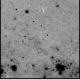
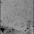
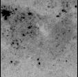
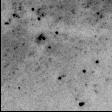
1 CHAPTER 10 Techniques for Background Measurement and Mosaicing In This Chapter... Introduction / 139 Chopping and Dithering Strategies / 141 Chopping and Dithering Patterns / 143 Examples / 147 Orienting Patterns / 152 Phase II Proposal Instructions for Patterns / 152 In this chapter we deal with techniques for mapping areas larger than the size of the field of view of the NICMOS cameras, and the issue of removing the thermal background of the telescope. Special procedures have been created to enable you to perform both these operations. Introduction Beyond 1.6 microns the contribution of the thermal background to NICMOS science images may be sufficiently high that a proper removal is required to obtain useful data (see Chapter 3). The problem is worsened by the fact that the background is variable on a time scale dictated by the thermal variations of the telescope. Currently, we don t know if the background level will be stable enough that general purpose background images can be built, for instance, as part of the NICMOS calibrations. Therefore, we encourage observers who are interested in the wavelength region beyond 1.6 microns to adopt the standard ground-based technique: to alternate on-target exposures with background exposure. To give an idea of how important it is to remove the background contamination from infrared 139


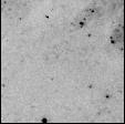
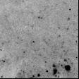
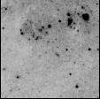
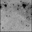
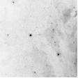
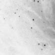
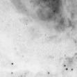
2 140 Chapter 10: Techniques for Background Measurement and Mosaicing images, we provide in Figure 10.1 below the example of a galaxy observed in the K band. The image on top is how the object looks after a complete data reduction, but before the background subtraction. The image at the bottom is the same object after the background has been subtracted. Figure 10.1: K Band Image of a Galaxy, Before and After Background Subtraction
3 Chopping and Dithering Strategies 141 It is possible that on board HST the thermal background will be more stable than in typical ground based situations. As a consequence it might be possible that the object-background interleaving can be carried out with a slower duty cycle. One objective of the SMOV phase will be to determine the required rate. Background images will be obtained by offsetting the telescope from the target to point to an empty region of the sky. The ability to routinely offset the telescope pointing will then be a fundamental operational requirement for NICMOS. To make it easier to plan observations beyond 1.6 microns, a set of pre-defined observing patterns was built; these patterns will combine exposures taken at different telescope pointings into an association. A pattern is a set of images of the same astronomical target obtained at pointings offset from each other, for the purpose, for instance, of creating background images. The associations of exposures are created for the purpose of processing simultaneously all the images from a single pattern. In addition to background subtraction at long NICMOS wavelengths, the patterns will be useful for creating maps of extended targets at any wavelength. Two distinct type of telescope motion are defined: Dither: Individual motions are limited to no more than 40 arcsecs. These are intended to be used to accomplish sequences of overlapping exposures for the construction of mosaics. Such sequences will be assembled into a single final image by the calibration pipeline. Chop: Motions up to 1800 arcsecs are permitted. These are intended for the measurement of the background at one or more locations significantly removed from the target pointing. Each non-contiguous background pointing will be assembled into its own final image in addition to the target pointing by the calibration pipeline. Telescope motions involve overheads for physically moving the telescope and, if necessary, for re-acquiring the guide stars. Therefore, significant time overheads may be incurred by observations which need background subtraction or propose to map extended regions of the sky. A careful estimate of the overheads associated with a specific observation or set of observations is necessary to evaluate the number of orbits required (see Chapter 9). Chopping and Dithering Strategies The most efficient strategy for removing the background from a science exposure strongly depends on the nature of the target and of the science to be accomplished. In general two types of targets can be defined: compact and extended.
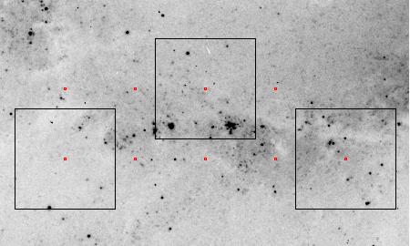
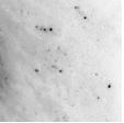
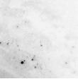
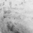
4 142 Chapter 10: Techniques for Background Measurement and Mosaicing Compact Objects For compact objects, such as point sources, background subtraction can be achieved by moving the target across the camera field of view (see Figure 10.2). A dither pattern, which involves movements of a few arcsecs from one exposure to the next, can then be used. This is an efficient way to build background images, since the target is present in each exposure, and a background image can be created from the stacking and filtering of all exposures. Figure 10.2: Dithering. Object 1st Integration Dither Object 2nd Integration Dither Extended Objects For an extended object which occupies a significant portion of the NICMOS field of view, the dithering technique does not apply to building background images. In this case, offsets to an adjacent field (chopping), chosen to be at least one camera field away in an arbitrary direction, are necessary. By offsetting in different directions a stacked and filtered sky can be created which removes the effect of contaminating objects in the offset fields (see Figure 10.3). As in the case of compact objects, these offsets might be quite small, but for large galaxies for example, they may need to be over considerable distances. The user will have the ability to specify the offset values and directions and their number in the Phase II instructions.
5 Chopping and Dithering Patterns 143 Figure 10.3: Chopping 1st Integration on object Telescope Offset Contaminating field sources 2nd Integration on object Telescope Offset in Different Direction Contaminating field source Chopping and Dithering Patterns There will be a set of 11 pre-designed patterns available for NICMOS observations. They include: 4 dither patterns, 4 chop patterns, and 3 dither-chop patterns. For each of these, the observer will be able to specify, during the Phase II Proposal submission, the total number of positions desired (2 to 40), the dither size (0 to 40 arcsecs), the chop size (0 to 1800 arcsecs), and the orientation of the
6 144 Chapter 10: Techniques for Background Measurement and Mosaicing pattern on the sky. The option POSTARG will be still available for offsetting the telescope and creating custom-design patterns, but there are a number of advantages in using the pre-designed patterns: They simplify the specification of complex observations in the Phase II proposal. All the observations pertaining to a pattern result in one association and are simultaneously calibrated and combined in the data calibration pipeline, including background calibration, cosmic ray removal, and flat field averaging. Observations obtained with POSTARG do not result in associations, and will have to be combined manually by the observer. They permit the observation of a mosaic with a fixed position angle without fixing spacecraft roll, which increases the number of opportunities to schedule the observations. Multiple exposures may be obtained at each position by the use of the NEXP optional parameter. These may be useful for cosmic ray removal. The 11 patterns are listed in Table 10.1, together with applicable parameters, such as the allowed values for the number of steps in the pattern (Num Pos), for the dither size and for the chop size. In addition, the figure number where the pattern is graphically shown is given in column 5 of Table Offset sizes and number of steps in a pattern affect the amount of overhead time required to perform an observation (see Chapter 9). The effects of dithering or chopping on an astronomical image are shown in a set of examples in the next section. Table 10.1: NICMOS Pre-designed Observing Patterns and Parameters Pattern Name Num. Pos. Dither Size Chop Size See Figure NONE (default) NA NA NA SPIRAL-DITH NA Fig SQUARE-WAVE-DITH NA Fig XSTRIP-DITH NA Fig YSTRIP-DITH NA Fig ONE-CHOP 2-40 NA Fig TWO-CHOP 2-40 NA Fig FOUR-CHOP 2-40 NA Fig EIGHT-CHOP 2-40 NA Fig SPIRAL-DITH-CHOP Fig XSTRIP-DITH-CHOP Fig YSTRIP-DITH-CHOP Fig. 10.6
7 Dither Patterns Chopping and Dithering Patterns 145 The dither patterns are recommended for the background subtraction from observations of point sources (beyond 1.6 microns), for the construction of mosaics (maps) of regions of the sky, and for the reduction of flat field uncertainties. The four dither patterns are called SPIRAL-DITH, SQUARE-WAVE-DITH, XSTRIP-DITH, and YSTRIP-DITH. Most of the names are self-explanatory: the SPIRAL-DITH pattern produces a spiral around the first pointing; the SQUARE-WAVE-DITH pattern covers extended regions by moving along a square-wave shape; the XSTRIP-DITH and the YSTRIP-DITH patterns map a strip of the sky along the x and y directions of the detector (as defined in Figure 4.6). The difference between the XSTRIP-DITH and the YSTRIP-DITH patterns is in that the first moves by default along the grism dispersion axis, while the second moves orthogonal to the grism dispersion axis. The four patterns are illustrated below: Figure 10.4: Dither Patterns SPIRAL-DITH SQUARE-WAVE-DITH XSTRIP-DITH YSTRIP-DITH Chop Patterns The chop patterns are recommended for measuring the background adjacent to extended targets. For each chop pattern, half of the exposures are taken on the
8 146 Chapter 10: Techniques for Background Measurement and Mosaicing target (position 1). The names of the chop patterns are: ONE-CHOP, TWO-CHOP, FOUR-CHOP, and EIGHT-CHOP. The ONE-CHOP pattern produces one image of the target and one image of the background. the TWO-CHOP pattern produces one image (with two exposures) of the target and two background images, with the background fields positioned on opposite sides of the target. The two other patterns increase the number of target-background pairs to four and eight, respectively. A large number of background images may be required if they contain a large number of contaminating sources or if the background is highly structured. The four chop patterns are shown in the figure below: Figure 10.5: Chop Patterns 1 2 ONE-CHOP 4 TWO-CHOP FOUR-CHOP 12 8 EIGHT-CHOP Combined Patterns The combined patterns permit dithering interleaved with chops to measure the background. They are recommended for simultaneous mapping and background subtraction during observations of extended targets, beyond 1.6 microns. Three combined patterns are implemented: SPIRAL-DITH-CHOP, XSTRIP-DITH-CHOP, and YSTRIP-DITH-CHOP. Their characteristics are analogous to the dither patterns SPIRAL-DITH, XSTRIP-DITH, and YSTRIP-DITH, respectively, with the addition that each dither step is coupled with a background image obtained by chopping. The three combined patterns are shown in Figure 10.6.
9 Examples 147 Figure 10.6: Combined Patterns SPIRAL-DITH-CHOP DITH-SIZE CHOP-SIZE YSTRIP-DITH-CHOP XSTRIP-DITH-CHOP DITH-SIZE CHOP-SIZE Examples The next few pages show a few selected examples of how the patterns work on astronomical observations.

10 148 Chapter 10: Techniques for Background Measurement and Mosaicing Figure 10.7: Square Wave Dither Images Taken: #2 #3 #6 #7 #1 #4 #5 #8 #9


11 Examples 149 Figure 10.8: Two-Chop Pattern #1 #2 Images Taken: #4 #3


12 150 Chapter 10: Techniques for Background Measurement and Mosaicing Figure 10.9: Four-Chop Pattern Images Taken: #1 #2 #3 #4 #5 #6 #7 #8


13 Examples 151 Figure 10.10: Spiral-Dith-Chop Pattern Target Background CHOP #9 #7 #5 #10 #8 #6 #11 #1 #3 #12 #2 #4 #13 #15 #14 #16 Sequence of Frames #9 #7 #5 #10 #8 #6 #11 #1 #3 #12 #2 #4 #13 #15 #14 #16
14 152 Chapter 10: Techniques for Background Measurement and Mosaicing Orienting Patterns Observations will often require that patterns are executed with specific position angles (PA) on the sky. For instance an observer may need to map an elongated region with PA=n degrees on the sky, using the SQUARE-WAVE-DITH pattern. Since the use of the ORIENT special requirement usually constrains the scheduling opportunities for a target (and may result in the unavailability of suitable guide stars), NICMOS implements an optional parameter called PATTERN-ORIENT (see next section). With this parameter, the orientation of the pattern on the sky can be set independently of the orientation of the three NICMOS detectors (and vice-versa). If a specific orientation of the detectors is also required, then the observatory level special requirement ORIENT must be set together with PATTERN-ORIENT. The default value for PATTERN-ORIENT is DETECTOR, and the pattern motions are in the NICMOS (x-y) focal plane orientation, i.e., rotated 225 degrees from the U3 axis. The orientation of the patterns on the sky is then determined by the orientation of the telescope with the ORIENT special requirement. Other values for the PATTERN-ORIENT parameter are given by the standard convention for PA, from 0.0 to 360.0, North through East. For example, the XSTRIP-DITH pattern with PATTERN-ORIENT=0 will track from East to West on the sky (the +Y axis is pointing North), and with PATTERN-ORIENT=45 from Southeast to Northwest. The YSTRIP-DITH pattern with PATTERN-ORIENT=0 will track from North to South. Phase II Proposal Instructions for Patterns We discuss the Phase II instructions for patterns in this section in order to illustrate the options available, however, this is not an exhaustive description and is not the appropriate reference to use when preparing a Phase II proposal. At that stage you should refer to the Institute s Phase II Proposal Instructions, which contain a complete and up-to-date guide. This section is not crucial for preparing the Phase I proposal, but it may be relevant to know beforehand which parameters will be available, and what values these parameters can have. One, and only one, pattern may be defined on an individual exposure logsheet line. A pattern may only be specified on the prime NICMOS camera. The motions between each exposure are carried out by expanding the pattern into a sequence of individual exposures separated by POSTARG operations. The set of exposures resulting from a pattern is called an association. A number of optional parameters are implemented for associations, and are listed below.
15 Parameters Phase II Proposal Instructions for Patterns 153 PATTERN=NONE (default) or Pattern_Name (see Table 10.1). NUM-POS = 2 to 40 (number of steps in dither or chop pattern to perform). DITH-SIZE = 0.0 to 40.0 (size of each step in arcsecs). CHOP-SIZE = 0.0 to (size of each step in arcsecs). OFFSET=SAM (default), (use SAMs; gyros for large moves with re-acquire); SAM-NO-REACQ, (use SAMs; do not attempt to re-acquire guide stars); SAM-NO-GYRO, (use SAMs; must use same or new guide stars). PATTERN-ORIENT=DETECTOR (default), (move in detector X-Y system) degrees from PA=0 increasing to East (Note that this does not constrain telescope roll; use existing ORIENT requirement). Types of Motions The OFFSET parameter defines which type of telescope motion will be performed during a pattern, in order to dither or chop. Telescope motions fall into three categories: Small angle motions (SAMs) where FGS Fine Lock guiding is maintained. Such SAMs are typically limited to < 2 arcmins from the point of the initial guide star acquisition. This is the practical limit of the radial extent of the pattern. Often it will be smaller due to guide star availability. SAMs without FGS guiding (i.e., GYRO HOLD pointing control). These are necessary for larger motions (> 2 arcmins). The telescope will drift at a rate of 1 to 2 milli-arcsecs per second of time (elapsed time not exposure time). SAMs with RE-ACQuisitions at each return to the target position. This can be used to chop between a target and an offset background measurement pointing (which would be observed with GYRO HOLD pointing control). The available options for OFFSET are: SAM, the default, will use guide stars whenever possible. If a motion, or the sequence of motions, moves the telescope sufficiently from the original position that guide stars are no longer available then exposures will be obtained using GYRO HOLD. If a subsequent motion returns the telescope to a point where the original guide stars become available then it will RE-ACQuire the guide stars. This incurs an overhead of ~3 minutes for each RE-ACQuisition. SAM-NO-REACQ will use guide stars (FGS Fine Lock) until the first instance in the pattern when guide stars become unavailable. The remainder of the pattern will be executed using GYRO HOLD pointing control.
16 154 Chapter 10: Techniques for Background Measurement and Mosaicing SAM-NO-GYRO will use guide stars for all exposures. If guide stars are not available, the observation cannot be scheduled.
Calibration Goals and Plans
 CHAPTER 13 Calibration Goals and Plans In This Chapter... Expected Calibration Accuracies / 195 Calibration Plans / 197 This chapter describes the expected accuracies which should be reached in the calibration
Improving the Absolute Astrometry of HST Data with GSC-II
 The 2005 HST Calibration Workshop Space Telescope Science Institute, 2005 A. M. Koekemoer, P. Goudfrooij, and L. L. Dressel, eds. Improving the Absolute Astrometry of HST Data with GSC-II A. M. Koekemoer,
NICMOS Status and Plans
 1997 HST Calibration Workshop Space Telescope Science Institute, 1997 S. Casertano, et al., eds. NICMOS Status and Plans Rodger I. Thompson Steward Observatory, University of Arizona, Tucson, AZ 85721
Relative Astrometry Within ACS Visits
 Instrument Science Report ACS 2006-005 Relative Astrometry Within ACS Visits Richard L. White August 07, 2006 ABSTRACT The log files from APSIS, the ACS science team s image processing pipeline, have been
The HST Set of Absolute Standards for the 0.12 µm to 2.5 µm Spectral Range
 Instrument Science Report CAL/SCS-010 The HST Set of Absolute Standards for the 0.12 µm to 2.5 µm Spectral Range L. Colina, R. Bohlin, D. Calzetti, C. Skinner, S. Casertano October 3, 1996 ABSTRACT A proposal
TECHNICAL MEMORANDUM
 When there is a discrepancy between the information in this technical report and information in JDox, assume JDox is correct. TECHNICAL MEMORANDUM Title: Sample Target Acquisition Scenarios for JWST Authors:
Breathing, Position Drift, and PSF Variations on the UVIS Detector
 SPACE TELESCOPE SCIENCE INSTITUTE Operated for NASA by AURA Instrument Science Report WFC3 1-1 Breathing, Position Drift, and PSF Variations on the UVIS Detector L. Dressel July 13, 1 ABSTRACT This study
PACS Wavelength Switching AOT release note
 PACS Wavelength Switching AOT release note 1 Prepared by the PACS ICC 20 January 2010 Wavelength switching release note version of 03-dec-2009 updated with full dynamic range saturation limits. Differences
AAG TPoint Mapper (Version 1.40)
") AAG TPoint Mapper (Version 1.40) AAG_TPointMapper works together with Maxim DL, Pinpoint, TheSky6 and TPoint to automate the process of building a TPoint model for a GOTO telescope connected to TheSky6.
AAG TPoint Mapper (Version 1.40) AAG_TPointMapper works together with Maxim DL, Pinpoint, TheSky6 and TPoint to automate the process of building a TPoint model for a GOTO telescope connected to TheSky6.
James Webb Space Telescope Cycle 1 Call for Proposals
 James Webb Space Telescope Cycle 1 Call for Proposals Stefanie Milam JWST Deputy Project Scientist for Planetary John Stansberry Solar System Lead, STScI Bryan Holler Solar System Scientist, STScI Getting
The in-orbit wavelength calibration of the WFC G800L grism
 The in-orbit wavelength calibration of the WFC G800L grism A. Pasquali, N. Pirzkal, J.R. Walsh March 5, 2003 ABSTRACT We present the G800L grism spectra of the Wolf-Rayet stars WR45 and WR96 acquired with
Performance of the NICMOS ETC Against Archived Data
 Performance of the NICMOS ETC Against Archived Data M. Sosey June 19, 2001 ABSTRACT A robust test of the newest version of the NICMOS Exposure Time Calculator (ETC) was conducted in order to assess its
Early-Science call for observing time with SAM-FP
 Early-Science call for observing time with SAM-FP 1. General description SOAR is opening a call for proposals for early-science with SAM-FP in 2016B, for 4 nights (September 29 October 2, 2016). SAM-FP
NAOYUKI TAMURA Subaru Instrument Astronomer Subaru Telescope, NAOJ
 FMOS status tt report Science workshop 2011.02.2802 28-03.0202 NAOYUKI TAMURA Subaru Instrument Astronomer Subaru Telescope, NAOJ * Overview * Recent history & current status t * Schedule & future plan
High Signal-to-Noise, Differential NICMOS Spectrophotometry
 Instrument Science Report NICMOS 2003-001 High Signal-to-Noise, Differential NICMOS Spectrophotometry R.L. Gilliland, S. Arribas January 7, 2003 ABSTRACT We report analysis for NICMOS CAL/9642, High S/N
Ivan Valtchanov Herschel Science Centre European Space Astronomy Centre (ESAC) ESA. ESAC,20-21 Sep 2007 Ivan Valtchanov, Herschel Science Centre
 ESA. ESAC,20-21 Sep 2007 Ivan Valtchanov, Herschel Science Centre") SPIRE Observing Strategies Ivan Valtchanov Herschel Science Centre European Space Astronomy Centre (ESAC) ESA Outline SPIRE quick overview Observing with SPIRE Astronomical Observation Templates (AOT)
SPIRE Observing Strategies Ivan Valtchanov Herschel Science Centre European Space Astronomy Centre (ESAC) ESA Outline SPIRE quick overview Observing with SPIRE Astronomical Observation Templates (AOT)
Transiting Exoplanet in the Near Infra-red for the XO-3 System
 Transiting Exoplanet in the Near Infra-red for the XO-3 System Nathaniel Rodriguez August 26, 2009 Abstract Our research this summer focused on determining if sufficient precision could be gained from
SPOT Meeting # 7 Overview and Summary. SOFIA USERS GROUP Sept 17, 2012
 SPOT Meeting # 7 Overview and Summary SOFIA USERS GROUP Sept 17, 2012 Eric Becklin and Pasquale Temi 1 1 Outline SOFIA Pointing Optimization Team (SPOT) Overview Tracking and Pointing. Guide Camera Upgrades
COS FUV Dispersion Solution Verification at the New Lifetime Position
 SPACE TELESCOPE SCIENCE INSTITUTE Operated for NASA by AURA Instrument Science Report COS 2013-06(v1) COS FUV Dispersion Solution Verification at the New Lifetime Position Paule Sonnentrucker 1, Julia
NIRSpec Multi-Object Spectroscopy of Distant Galaxies
 NIRSpec Multi-Object Spectroscopy of Distant Galaxies Pierre Ferruit & the NIRSpec GTO team & the NIRCam-NIRSpec galaxy assembly collaboration Proposal Planning Workshop STScI 15 May 2017 ESA UNCLASSIFIED
Open Cluster Photometry: Part II
 Project 4 Open Cluster Photometry: Part II Observational Astronomy ASTR 310 Fall 2005 1 Introduction The objective of this and the previous project is to learn how to produce color-magnitude diagrams of
Observer Anomaly(?): Recent Jitter and PSF Variations
: Recent Jitter and PSF Variations") Instrument Science Report TEL 2005-01 Observer Anomaly(?): Recent Jitter and PSF Variations R. L. Gilliland gillil@stsci.edu February 2005 Abstract An anomaly in the HST Pointing Control System (PCS) has
Instrument Science Report TEL 2005-01 Observer Anomaly(?): Recent Jitter and PSF Variations R. L. Gilliland gillil@stsci.edu February 2005 Abstract An anomaly in the HST Pointing Control System (PCS) has
JWST Fine Guidance Sensor Calibration
 The 2010 STScI Calibration Workshop Space Telescope Science Institute, 2010 Susana Deustua and Cristina Oliveira, eds. JWST Fine Guidance Sensor Calibration P. Chayer, S. Holfeltz, E. Nelan Space Telescope
September 2008 LGS Science Observing Plan 9/18/08 v1.1, A. Bouchez
 1. General Procedures September 2008 LGS Science Observing Plan 9/18/08 v1.1, A. Bouchez We should attempt to complete highest priority observing programs first, before proceeding to lower priority programs.
FORCAST: Science Capabili2es and Data Products. William D. Vacca
 FORCAST: Science Capabili2es and Data Products William D. Vacca Faint Object infrared Camera for the SOFIA Telescope (FORCAST) SWC (blue) Light from telescope LWC (red) Facility Instrument PI: Terry Herter
1. Give short answers to the following questions. a. What limits the size of a corrected field of view in AO?
 Astronomy 418/518 final practice exam 1. Give short answers to the following questions. a. What limits the size of a corrected field of view in AO? b. Describe the visibility vs. baseline for a two element,
Scattered Light from the Earth Limb Measured with the STIS CCD
 Instrument Science Report STIS 98 21 Scattered Light from the Earth Limb Measured with the STIS CCD Dick Shaw, Merle Reinhart, and Jennifer Wilson 17 June 1998 ABSTRACT We describe a recent program to
Introduction to SDSS -instruments, survey strategy, etc
 Introduction to SDSS -instruments, survey strategy, etc (materials from http://www.sdss.org/) Shan Huang 17 February 2010 Survey type Status Imaging and Spectroscopy Basic Facts SDSS-II completed, SDSS-III
Photometric Studies of GEO Debris
 Photometric Studies of GEO Debris Patrick Seitzer Department of Astronomy, University of Michigan 500 Church St. 818 Dennison Bldg, Ann Arbor, MI 48109 pseitzer@umich.edu Heather M. Cowardin ESCG/Jacobs
Commissioning of the Hanle Autoguider
 Commissioning of the Hanle Autoguider Copenhagen University Observatory Edited November 10, 2005 Figure 1: First light image for the Hanle autoguider, obtained on September 17, 2005. A 5 second exposure
Announcement of Opportunity for Open Time. SPIRE PACS Parallel Mode Observers' Manual
 Announcement of Opportunity for Open Time SPIRE PACS Parallel Mode Observers' Manual HERSCHEL-HSC-DOC-0883, Version 2.1 4-October-2011 SPIRE PACS Parallel Mode Observers' Manual Published version 2.1,
MEMORANDUM. Focal-Point: Point on the focal plane where the sharpest PSF is located.
 CHANDRA X-ray Center 60 Garden St., Cambridge Massachusetts 02138 USA MEMORANDUM Date: November 1, 2014 From: Ping Zhao To: CXC Subject: Chandra Optical Axis, Aimpoint and Their Drifts File: oxap memo.tex
FPA#64 and new substrate removed FPAs for WFC3-IR: a trade-off study
 Instrument Science Report WFC3 2005-019 ` and new substrate removed FPAs for WFC3-IR: a trade-off study Massimo Robberto (ESA/STSI) Abstract Recent tests indicate that the flight detectors selected for
Problem Solving. radians. 180 radians Stars & Elementary Astrophysics: Introduction Press F1 for Help 41. f s. picture. equation.
 Problem Solving picture θ f = 10 m s =1 cm equation rearrange numbers with units θ factors to change units s θ = = f sinθ fθ = s / cm 10 m f 1 m 100 cm check dimensions 1 3 π 180 radians = 10 60 arcmin
High accuracy imaging polarimetry with NICMOS
 Rochester Institute of Technology RIT Scholar Works Articles 11-6-28 High accuracy imaging polarimetry with NICMOS Daniel Batcheldor G. Schneider D.C. Hines Follow this and additional works at: http://scholarworks.rit.edu/article
NEWFIRM Quick Guide for Proposal Preparation
 NEWFIRM Quick Guide for Proposal Preparation Ron Probst NEWFIRM Instrument Scientist September 2008 NEWFIRM is a 1-2.4 micron IR camera for the NOAO 4-m telescopes. It has a flexible complement of broad
Goals of the meeting. Catch up with JWST news and developments: ERS and GO call for proposals are coming!!
 Welcome Goals of the meeting Catch up with JWST news and developments: ERS and GO call for proposals are coming!! What is JWST capable of (focus on H 2 spectroscopy)? What do we need to do (models, lab)
ACS PSF variations with temperatures
 Instrument Science Report ACS 07-12 ACS PSF variations with temperatures Kailash C. Sahu, Matt Lallo, Russ Makidon September 18, 2007 ABSTRACT We have used the HST ACS/WFC observations of a Galactic bulge
Announcement of Opportunity AKARI (ASTRO-F)
") Announcement of Opportunity AKARI (ASTRO-F) CALL FOR OBSERVING PROPOSALS for the AKARI Post-Helium (phase 3) mission 2 nd year of Operations (October 2009 October 2010) Policies and procedures 27 May 2009
Announcement of Opportunity AKARI (ASTRO-F) CALL FOR OBSERVING PROPOSALS for the AKARI Post-Helium (phase 3) mission 2 nd year of Operations (October 2009 October 2010) Policies and procedures 27 May 2009
Lab 4 Radial Velocity Determination of Membership in Open Clusters
 Lab 4 Radial Velocity Determination of Membership in Open Clusters Sean Lockwood 1, Dipesh Bhattarai 2, Neil Lender 3 December 2, 2007 Abstract We used the Doppler velocity of 29 stars in the open clusters
Photometry with Iris Photometry with Iris
 Author: Daniel Duggan & Sarah Roberts - Faulkes Telescope Project Introduction Photometry is the measurement of the intensity or brightness of an astronomical object, such as a star or galaxy by adding
Narrowband Imaging, or How to Image in Downtown Portland. Duncan Kitchin OMSI Astro Imaging Conference 2010
 Narrowband Imaging, or How to Image in Downtown Portland Duncan Kitchin OMSI Astro Imaging Conference 2010 Agenda Sources of noise in astro images Selectively removing light pollution Narrowband filters
Telescopio Nazionale Galileo. GIARPS mode. Short Observer s Guide. Prepared by Avet Harutyunyan
 Telescopio Nazionale Galileo GIARPS mode Short Observer s Guide Prepared by Avet Harutyunyan Document version: 1.0 Date: 20/11/2017 2 GIARPS mode Short Observer s Guide Change record Version Date Section/Page
MEMORANDUM. Focal-Point: Point on the focal plane where the sharpest PSF is located.
 CHANDRA X-ray Center 60 Garden St., Cambridge Massachusetts 02138 USA MEMORANDUM Date: October 16, 2017 From: Ping Zhao To: CXC Subject: Chandra Optical Axis and Aimpoint File: oxap memo 2017.tex Version:
Common questions when planning observations with DKIST Jan 30, 2018
 Common questions when planning observations with DKIST Jan 30, 2018 1. Can the DKIST instruments work together? All instruments except Cryo-NIRSP can work together and with Adaptive Optics (AO). All can
11041,11042,11043: ACS CCD Daily Monitor
 11041,11042,11043: ACS CCD Daily Monitor Purpose. This program consists of a series of basic tests to measure the readnoise and dark current of the ACS CCDs and to track the growth of hot pixels. The images
Study of Physical Characteristics of High Apogee Space Debris
 Study of Physical Characteristics of High Apogee Space Debris Yongna Mao, Jianfeng Wang, Xiaomeng Lu, Liang Ge, Xiaojun Jiang (National Astronomical Observatories, Beijing, 100012, China) Abstract Date
Galactic Rotation Activity*
 Galactic Rotation Activity* Neutral hydrogen atoms (H I) consist of a single proton and a single electron. The electron and proton can spin in the same direction (parallel) or in the opposite direction
Calibration of ACS Prism Slitless Spectroscopy Modes
 The 2005 HST Calibration Workshop Space Telescope Science Institute, 2005 A. M. Koekemoer, P. Goudfrooij, and L. L. Dressel, eds. Calibration of ACS Prism Slitless Spectroscopy Modes S. S. Larsen, M. Kümmel
Solar System Science with JWST!
 Solar System Science with JWST! Dean C. Hines Space Telescope Science Institute JWST Imaging Modes! Mode Imaging Aperture Mask Interferometry Coronography Instrument Wavelength (microns) Pixel Scale (arcsec)
COS FUV Focus Determination for the G140L Grating
 Instrument Science Report COS 2012-01 COS FUV Focus Determination for the G140L Grating Parviz Ghavamian 1 Space Telescope Science Institute, Baltimore, MD October 03, 2012 ABSTRACT The procedures for
Polar alignment in 5 steps based on the Sánchez Valente method
 1 Polar alignment in 5 steps based on the Sánchez Valente method Compared to the drift alignment method, this one, allows you to easily achieve a perfect polar alignment in just one step. By "perfect polar
Notes: Reference: Merline, W. J. and S. B. Howell (1995). "A Realistic Model for Point-sources Imaged on Array Detectors: The Model and Initial
. A Realistic Model for Point-sources Imaged on Array Detectors: The Model and Initial") Notes: Notes: Notes: Reference: Merline, W. J. and S. B. Howell (1995). "A Realistic Model for Point-sources Imaged on Array Detectors: The Model and Initial Results." Experimental Astronomy 6: 163-210.
Notes: Notes: Notes: Reference: Merline, W. J. and S. B. Howell (1995). "A Realistic Model for Point-sources Imaged on Array Detectors: The Model and Initial Results." Experimental Astronomy 6: 163-210.
Spitzer Space Telescope
 Spitzer Space Telescope (A.K.A. The Space Infrared Telescope Facility) The Infrared Imaging Chain 1/38 The infrared imaging chain Generally similar to the optical imaging chain... 1) Source (different
Determining Polar Axis Alignment Accuracy
 Determining Polar Axis Alignment Accuracy by Frank Barrett nd Edition 9/1/016 Abstract: In order to photograph dim celestial objects, long exposures on the order of minutes or hours are required. To perform
Remote and Robotic Operation of the Dominion Astrophysical Observatory 1.2-m Telescope and McKellar Spectrograph
 Remote and Robotic Operation of the Dominion Astrophysical Observatory 1.2-m Telescope and McKellar Spectrograph David Bohlender, Dmitry Monin, and Les Saddlemyer (NRC/HIA) The DAO Telescopes: The Challenge...
Comparative study of the efficiency of various JWST coronagraph observation strategies.
 When there is a discrepancy between the information in this technical report and information in JDox, assume JDox is correct. JWST-STScI-004165, SM-12 Revision - Space Telescope Science Institute JAMES
Gemini Integration Time Calculators
 Gemini Integration Time Calculators Phil Puxley SPE-C-G0076 Version 1.1; June 1998 Version History: 1.0 June 1998; first draft. 1.1 June 1998; following comments from Ted von Hippel and Joe Jensen. 1.
Optical/NIR Spectroscopy A3130. John Wilson Univ of Virginia
 Optical/NIR Spectroscopy A3130 John Wilson Univ of Virginia Topics: Photometry is low resolution spectroscopy Uses of spectroscopy in astronomy Data cubes and dimensionality challenge Spectrograph design
Flux Units and Line Lists
 APPENDIX 2 Flux Units and Line Lists In This Appendix... Infrared Flux Units / 255 Formulae / 258 Look-up Tables / 259 Examples / 266 Infrared Line Lists / 266 In this chapter we provide a variety of background
Updated flux calibration and fringe modelling for the ACS/WFC G800L grism
 Updated flux calibration and fringe modelling for the ACS/WFC G800L grism H. Kuntschner, M. Kümmel, J. R. Walsh January 25, 2008 ABSTRACT A revised flux calibration is presented for the G800L grism with
JWST/NIRSpec. P. Ferruit. (ESA JWST project scientist) Slide #1
 Slide #1") P. Ferruit (ESA JWST project scientist)! Slide #1 Acknowledgements Thanks for giving me the opportunity to present the NIRSpec instrument. All along this presentation you will see the results of work conducted
P. Ferruit (ESA JWST project scientist)! Slide #1 Acknowledgements Thanks for giving me the opportunity to present the NIRSpec instrument. All along this presentation you will see the results of work conducted
HETDEX Overview. Hobby Eberly Telescope Dark Energy Experiment. HETDEX is: HETDEX enables a lot of ancillary science. HETDEX Science Workshop Feb 09
 Introduction to WFU, VIRUS, & DEX Gary J. Hill, McDonald Observatory Scope What HETDEX is WFU VIRUS DEX survey parameters 1 HETDEX is: Upgrade of HET to have a new 22 arcmin wide field of view Deployment
Telescopes. Optical Telescope Design. Reflecting Telescope
 Telescopes The science of astronomy was revolutionized after the invention of the telescope in the early 17th century Telescopes and detectors have been constantly improved over time in order to look at
You, too, can make useful and beautiful astronomical images at Mees: Lesson 3
 You, too, can make useful and beautiful astronomical images at Mees: Lesson 3 Calibration and data reduction Useful references, besides Lessons 1 and 2: The AST 142 Projects manual: http://www.pas.rochester.edu/~dmw/ast142/projects/project.pdf
Cross-Talk in the ACS WFC Detectors. I: Description of the Effect
 Cross-Talk in the ACS WFC Detectors. I: Description of the Effect Mauro Giavalisco August 10, 2004 ABSTRACT Images acquired with the Wide Field Channel (WFC) of the Advanced Camera for Surveys (ACS) are
Tools of Astronomy Tools of Astronomy
 Tools of Astronomy Tools of Astronomy The light that comes to Earth from distant objects is the best tool that astronomers can use to learn about the universe. In most cases, there is no other way to study
The Effective Spectral Resolution of the WFC and HRC Grism
 The Effective Spectral Resolution of the WFC and HRC Grism A. Pasquali, N. Pirzkal, J.R. Walsh, R.N. Hook, W. Freudling, R. Albrecht, R.A.E. Fosbury March 7, 2001 ABSTRACT We present SLIM simulations of
Note on OSIRIS Wavelength Calibrations D. Le Mignant, Oct. 5, 2007
 Note on OSIRIS Wavelength Calibrations D. Le Mignant, Oct. 5, 2007 1. Observations and data reduction In this short note, we report on some on-going analysis of OSIRIS data in an effort to document our
Image Acquisition Best Practices. Richard A. Bennion Ewell Observatory
 Image Acquisition Best Practices Richard A. Bennion Ewell Observatory QTR MILE: 16.2 QTR MILE: 14.9 15.4 13.2 16.7 Imaging Performance By what standard do we measure imaging performance? What is good data
Spitzer Space Telescope Calibration Strategy: The Use of Asteroids
 Spitzer Space Telescope Calibration Strategy: The Use of Asteroids 1, J. Stansberry 2, C. Engelbracht 2, M. Blaylock 2, A. Noriega-Crespo 1 2004 December 3 Herschel Calibration Workshop, Leiden, The Netherlands
MICRO-GUIDE Reticle Eyepiece Manual
 MICRO-GUIDE Reticle Eyepiece Manual 2015 Micro-Guide system design by Peter Stättmayer Munich and The Micro Guide eyepiece is like four eyepieces in one. With four separate scales on one reticle you can
Science Drivers for NGST Small-Angle Maneuvers
 STScI-NGST-R-0002A Space Telescope Science Institute Next Generation Space Telescope Mission Science Drivers for NGST Small-Angle Maneuvers 19 April 2000 Issue A REVISION HISTORY ISSUE DESCRIPTION DATE
Reduction procedure of long-slit optical spectra. Astrophysical observatory of Asiago
 Reduction procedure of long-slit optical spectra Astrophysical observatory of Asiago Spectrograph: slit + dispersion grating + detector (CCD) It produces two-dimension data: Spatial direction (x) along
High Precision Exoplanet Observations with Amateur Telescopes
 High Precision Exoplanet Observations with Amateur Telescopes Dennis M. Conti Chair, AAVSO Exoplanet Section Member, KELT Follow-up Team Member, TESS TFOP Working Group HAL Meeting: October 19, 2017 1
Observing with the Infrared Spectrograph
 Observing with the Infrared Spectrograph C. Grillmair, L. Armus GO Workshop 21-22 November 2002 Outline 1) Meet the IRS IST 2) Basic IRS capabilities 3) Observing and readout modes 4) Data products and
ADAS Guide to choosing the right Telescope. Produced by Members of the Society, Nov 2017
 ADAS Guide to choosing the right Telescope Produced by Members of the Society, Nov 2017 Choosing a Telescope Telescope Types Telescope Features Visual or Astrophotography use? Telescope Package or Separate
New Northern Hemisphere Variables
 222 New Northern Hemisphere Variables Donald Davies 23819 Ladeene Avenue, Torrance, CA 90505 Received October 5, 2005; revised November 16, 2005; accepted December 1, 2005 Abstract A survey looking for
Life Cycle of Stars. Photometry of star clusters with SalsaJ. Authors: Daniel Duggan & Sarah Roberts
 Photometry of star clusters with SalsaJ Authors: Daniel Duggan & Sarah Roberts Photometry of star clusters with SalsaJ Introduction Photometry is the measurement of the intensity or brightness of an astronomical
APLUS: A Data Reduction Pipeline for HST/ACS and WFC3 Images
 APLUS: A Data Reduction Pipeline for HST/ACS and WFC3 Images Wei Zheng 1,AmitSaraff 2,3,LarryBradley 4,DanCoe 4,AlexViana 4 and Sara Ogaz 4 1 Department of Physics and Astronomy, Johns Hopkins University,
Hanle Echelle Spectrograph (HESP)
") Hanle Echelle Spectrograph (HESP) Bench mounted High resolution echelle spectrograph fed by Optical Fiber Second generation instrument for HCT The project is a technical collaboration between Indian Institute
Hanle Echelle Spectrograph (HESP) Bench mounted High resolution echelle spectrograph fed by Optical Fiber Second generation instrument for HCT The project is a technical collaboration between Indian Institute
Accuracy of VIMOS night-time and daytime wavelength calibrations
 Accuracy of VIMOS night-time and daytime wavelength calibrations Burkhard Wolff, Steffen Mieske, Juan Carlos Muñoz-Mateos, Sabine Möhler, Michael Hilker 10 December 2014 Abstract Night-time calibrations
1 The Preliminary Processing
 AY 257 Modern Observational Techniques...23 1 The Preliminary Processing Frames must be corrected for a bias level and quantum efficiency variations on all scales. For a minority of CCDs and most near-ir
ARISTARCHOS TELESCOPE 2.3 m
 National Observatory of Athens Institute of Astronomy & Astrophysics Helmos Observatory ARISTARCHOS TELESCOPE 2.3 m OBSERVER S COOKBOOK GETTING STARTED The program ZEISS GUI is selected and run in the
Lecture 8. October 25, 2017 Lab 5
 Lecture 8 October 25, 2017 Lab 5 News Lab 2 & 3 Handed back next week (I hope). Lab 4 Due today Lab 5 (Transiting Exoplanets) Handed out and observing will start Friday. Due November 8 (or later) Stellar
Low Surface Brightness Observations of Galaxy Disk Truncation with Different Obliquities
 Yale Observing Proposal Standard proposal Semester: 2014B Date: April 9, 2018 Low Surface Brightness Observations of Galaxy Disk Truncation with Different Obliquities PI: Professor Pieter Van DokkumStatus:
Time-series Photometry of Earth Flyby Asteroid 2012 DA14
 Time-series Photometry of Earth Flyby Asteroid 2012 DA14 Tsuyoshi Terai Subaru Telescope Asteroid populations Main-belt asteroids Dynamical evolution Near-Earth asteroids 1 Asteroids Spectral classification
SPIRE/PACS Parallel Mode
 SPIRE/PACS Parallel Mode Herschel Observation Planning Workshop ESAC, 20 21 September 2007, Sarah Leeks Herschel Science Centre European Space Astronomy Centre Research and Scientific Support Department
D.A.R.V. (DSLR / CCD Drift Alignment by Robert Vice)
") 1 of 5 5/2/2011 13:55 D.A.R.V. (DSLR / CCD Drift Alignment by Robert Vice) For many years I have spent time learning the Star drift method of alignment for my telescope. Although tedious, it has turned
1 of 5 5/2/2011 13:55 D.A.R.V. (DSLR / CCD Drift Alignment by Robert Vice) For many years I have spent time learning the Star drift method of alignment for my telescope. Although tedious, it has turned
Updates to the COS/NUV Dispersion Solution Zero-points
 Instrument Science Report COS 017-0 Updates to the COS/NUV Dispersion Solution Zero-points Rachel Plesha 1, Paule Sonnentrucker 1,, Cristina Oliveira 1, Julia Roman-Duval 1 1 Space Telescope Science Institute,
The Challenge of AZ Cas-Part 1. John Menke Barnesville, MD Abstract
 The Challenge of AZ Cas-Part 1 John Menke Barnesville, MD 20838 john@menkescientific.com www.menkescientific.com Abstract This is an interim report on observations of the spectrum of AZCas taken during
a) Set the declination to trace the winter Sun's path and rising and setting points in
 Set the declination to trace the winter Sun's path and rising and setting points in") Astronomy 3130 Spring 2017 Observation Lab 1 (Beta Version) Getting around the sky and observing with the 6 doghouse telescope As an observer, a primary skill is getting your telescope pointed to an appropriate
Astronomy 3130 Spring 2017 Observation Lab 1 (Beta Version) Getting around the sky and observing with the 6 doghouse telescope As an observer, a primary skill is getting your telescope pointed to an appropriate
COS Cycle 17: 20 programs 149 external orbits 446 internals FUV Detector Sensitivity Monitor 36 0 Oct. 3, 2010
 Prop. ID Title External Internal Status/End obs Cycle 17 11891 NUV MAMA Fold Distribution 0 2 last visit on hold 11894 NUV Detector Dark Monitor 0 114 Oct. 31, 2010 11896 NUV Spectroscopic Sensitivity
Extraction of Point Source Spectra from STIS Long Slit Data
 1997 HST Calibration Workshop Space Telescope Science Institute, 1997 S. Casertano, et al., eds. Extraction of Point Source Spectra from STIS Long Slit Data J. R. Walsh Spect Telescope European Coordinating
Astronomical "color"
 Astronomical "color" What color is the star Betelgeuse? It's the bright star at upper left in this picture of Orion taken by a student at the RIT Observatory. Orange? Red? Yellow? These are all reasonable
ALMA Observing Tool!
 ALMA Observing Tool Phase I: Observing Proposal Yu-Nung Su" ALMA User Workshop 2015" March 28, 2015 Introduction What is Observing Tool (OT)? provides a comprehensive set of interfaces (form and tool)
Attempts to Mitigate Trapping Effects in Scanned Grism Observations of Exoplanet Transits with WFC3/IR
 SPACE TELESCOPE SCIENCE INSTITUTE Operated for NASA by AURA WFC3 Instrument Science Report 2014-14 Attempts to Mitigate Trapping Effects in Scanned Grism Observations of Exoplanet Transits with WFC3/IR
A Search for Dark Matter in an Edge on Spiral Galaxy
 UNIVERSITY OF CALIFORNIA - SANTA CRUZ DEPARTMENT OF PHYSICS PHYS 136 PROFESSOR: PROCHASKA A Search for Dark Matter in an Edge on Spiral Galaxy Benjamin Stahl Team: A. Callahan (PI) & J. Gillette August
Public Release of NIKA Sunyaev-Zel'dovich Data
 Public Release of NIKA Sunyaev-Zel'dovich Data Explanatory supplement Contact : Remi Adam (radam@cefca.es) NIKA was used to image galaxy clusters using the Sunyaev-Zel dovich (SZ) effect. A total of six
FIVE FUNDED* RESEARCH POSITIONS
 OBSERVATION Sub-GROUP: 1. Masters (MSc, 1 year): Exploring extreme star-forming galaxies for SALT in the Sloan Digital Sky Survey 2. Masters (MSc,1 year): HI masses of extreme star-forming galaxies in