Lecture Set 5 Distributed Windings and Rotating MMF
|
|
|
- Gwen Chastity McCormick
- 6 years ago
- Views:
Transcription
1 Lecture Set 5 Distributed Windings and Rotating MMF S.D. Sudhoff Spring 2017
2 Distributed Windings and Rotating MMF Objective In this chapter, we will set the stage to study ac machinery including permanent magnet synchronous machines as well as induction machines Reading Power Magnetic Devices: A Multi-Objective Design Approach, , (Available through IEEE Xplore at no cost) 2


3 Parts of an AC Machine 3

4 Parts of an AC Machine Stator 4


5 Operation of AC Machines N-Pole: Flux leaves material S-Pole: Flux enters material 5

6 P-Pole Machines For given ac frequency having more than 2 poles reduces machine speed by P/2 6
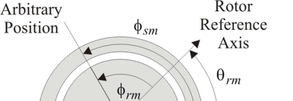

7 Position Measurement 7
8 Electrical Positions 8
9 Distributed Windings Thus far, we have mostly considered lumped windings. We must now consider distributed winding. This is a more difficult concept. Two Representations Discrete Winding Representation Continuous Winding Representation 9


10 Spring 2010 ECE321 10
11 Discrete Winding Representation Let N x,i denote number of conductors of a x- phase winding in the i th slot i designates the slot number x denotes winding or phase and is typically as, bs, or cs y is s for stator or r for rotor A positive value indicates the conductor directed out of the page 11
12 Slot and Tooth Locations φ = π (2i 2) / S + φ ys, i y ys,1 φ = π (2i 3) / S + φ yt, i y ys,1 12
13 Discrete Winding Representation S y i= 1 N x, i = 0 S y = N N u( N ) x x, i x, i i= 1 13
14 Developed Diagram 14
15 Continuous Winding Description Conductor density (conductors/rad): n x (φ ym ) x denotes winding/phase as, bs, or cs y is location ( s for stator, r for rotor) positive value indicates conductors out of the page For example, the a-phase conductor density may be given by n ( φ ) = N sin( Pφ / 2) N sin(3 Pφ / 2) as sm s1 sm s3 sm Total conductors per phase N 2π = n ( φ) u(n ( φ)) dφ xy xy xy 0 15
16 Symmetry Conditions N x, i+ 2 S / P = Nx, i y N + = N x, i S / P x, i y n ( φ + 4 π / P) = n ( φ ) x m x m n ( φ + 2 π / P) = n ( φ ) x m x m 16
17 Symmetry Conditions 17
18 Winding Arrangements N as [ ] = N
19 Winding Arrangements 19
20 The Winding Function The winding function is a measure of how many times a winding links flux at a given place The winding function will be used to Find self-inductance of a distributed winding Find mutual-inductance between distributed windings Find the mmf associated with a distributed winding It can be expressed in terms of both discrete and continuous winding descriptions 20
21 The Discrete Winding Function W x,i is the discrete winding function of phase x of the stator or rotor It is the number of times the winding links flux through the i th tooth It is the number of turns around tooth i 21
22 The Discrete Winding Function Consider the following N x, i +1 Tooth i+1 N x, i N x, i 1 Tooth i β turns α turns 22
23 The Discrete Winding Function N x, i +1 Tooth i+1 N x, i N x, i 1 Tooth i β turns α turns 23
24 The Discrete Winding Function N x, i +1 Tooth i+1 N x, i N x, i 1 Tooth i β turns α turns 24
25 The Discrete Winding Function 25
26 The Discrete Winding Description Summarizing: W S y / P 1 = N x,1 x, i 2 i= 1 W = + W N x, i 1 x, i x, i 26
27 Example Suppose we have [ ] T Nx = 10 27
28 Example Finally we obtain [ ] T Wx = 10 28
29 The Continuous Winding Function Notation φ = φ rm for rotor windings φ = φ sm for stator windings w x (φ) = winding function Number of times a winding links flux at position φ 29
30 The Continuous Winding Function 30
31 The Continuous Winding Function 31
32 The Continuous Winding Function 32
33 The Continuous Winding Function Thus we have 2 π / P m 1 w x ( φm ) = n x ( φm ) dφm n x ( φm ) dφm 2 φ
34 Example Consider the following geometry We might have as = 100sin( φsm ) Find the winding function n 34
35 Example 35
36 Example 36
37 Comparison of Winding Functions N as = N [ ] W as = N [ ] n = N 7.221sin( 2φ ) sin(6 φ ) ( ) as sm sm was = N cos( 2φsm ) cos(6 φsm )
38 Comparison of Winding Functions 38
39 Distributed MMF In a distributed machine, the MMF source is associated with a winding is a function of position as well as the current We will focus on the continuous winding distribution We can show F S ( φm ) = w x ( φm ) ix F ( φ ) = w ( φ ) i x X S R m x m x x X R F ( φ ) = F ( φ ) + F ( φ ) g m S m R m 39
40 Distributed MMF
41 Airgap MMF Before we start, define airgap MMF in a rotating machine: F stator ( φ ) = H ( φ ) d l g m m rotor Since the integration is in radial direction stator Fg ( φm ) = H r( φm ) dl rotor 41
42 Air Gap MMF Now consider the following 42
43 Air Gap MMF 43
44 Air Gap MMF 44
45 Air Gap MMF 45
46 Air Gap MMF 46
47 Air Gap MMF 47
48 Air Gap MMF 48
49 Distributed MMF Once we have the MMF what do we do with it??? 49
50 Air Gap Flux Density Thus we have B g ( φ ) m = µ 0 Fg ( φm ) g ( φm ) 50
51 Distributed MMF First, it gives the total field = F( φ) F ( φ) B = x X ( φ) x µ 0F( φ) g 51
52 Distributed MMF Second, it gives us the fields associated with a winding B x µ F = 0 g x ( φ) ( φ) 52
53 Example Suppose w as =100cos(4φ sm ); i as =5 A w bs =50sin(4φ sm ); i bs = 10 A g = 1 mm What is the peak B-field? At what position is the peak B-field? 53
54 Example 54
55 Example 55
56 Rotating MMF Another concept from the MMF is that the fields rotate 56
57 Rotating MMF in Two-Phase Systems Suppose n n as bs = N s = N And that i as = ( Pφ 2) sin sm / s ( Pφ 2) cos sm / cos( ω t + φ ) 2Is e i w w as bs = = 2N P 2N P s s cos sin ( Pφ / 2) sm ( Pφ / 2) sm i bs = sin( ω t + φ ) 2Is e i What is the MMF? 57
58 Rotating MMF in Two-Phase Systems 58
59 Rotating MMF in Two-Phase Systems 59
60 Rotating MMF in Two-Phase Systems Result F 2 2N si s = cos Pφ / 2 ω t ϕ P ( ) s sm e i 60
61 Affect of Number of Poles F 2 2N si s = cos Pφ / 2 ω t ϕ P ( ) s sm e i 61
62 Unbalanced Two-Phase Systems Let s consider another case. Again starting with 2N s F = cos ( Pφ / 2) i + sin ( Pφ / 2) i P ( ) s sm as sm bs Suppose the b-phase current is zero; the a- phase current given by i as = cos( ω t + φ ) 2Is e i 62
63 Unbalanced Two-Phase Systems 63
64 Unbalanced Two-Phase Systems 64
65 Unbalanced Two-Phase Systems 65
66 Rotating MMF in Three-Phase Systems In this case suppose n ( φ ) = N sin( Pφ / 2) N sin(3 Pφ / 2) as sm s1 sm s3 sm n ( φ ) = N sin( Pφ / 2 2 π / 3) N sin(3 Pφ / 2) bs sm s1 sm s3 sm n ( φ ) = N sin( Pφ / π / 3) N sin(3 Pφ / 2) cs sm s1 sm s3 sm Question: why would I do this? 66
67 Rotating MMF in Three-Phase Systems Proceeding, we have s1 s3 w as ( sm ) = cos( P sm / 2) cos(3 P sm / 2) Now φ 2N 2N P φ 3P φ φ 2N 2N P φ π 3P φ s1 s3 w bs ( sm ) = cos( P sm / 2 2 / 3) cos(3 P sm / 2) φ 2N 2N P φ π 3P φ s1 s3 w cs ( sm ) = cos( P sm / / 3) cos(3 P sm / 2) F ( φ ) = w ( φ ) i + w ( φ ) i + w ( φ ) i S sm as sm as bs sm bs cs sm cs 67
68 Rotating MMF in Three-Phase Systems Now let us assume a three-phase balanced set of currents i i bs cs i as = cos( ω t + φ ) 2Is e i 2I cos( ω t + φ 2π / 3) = s e i 2I cos( ω t + φ + 2π / 3) = s e i 68
69 Rotating MMF in Three-Phase Systems Combining yields F 3 2N I = cos / 2 P ( Pφ ω t φ ) s1 s S sm e i 69
70 Flux Linkage and Magnetizing Inductance Flux linkage: Inductance λx = λxl + λxm L xy = λ x due to iy i y 70
71 Flux Linkage and Magnetizing Inductance Partitioning Inductance Inductance Terms Lxy = Lxyl + Lxym L xyl = λ xl due to i y i y L xym = λ xm due to iy i y 71
72 Flux Linkage and Magnetizing Inductance We can show w ( ) w ( ) L µ rl dφ 2π λxym x φm y φm = xym = 0 iy 0 g( φm ) m 72
73 Flux Linkage and Magnetizing Inductance Stator dφ r φ 73
74 Flux Linkage and Magnetizing Inductance Stator dφ r φ 74
75 Flux Linkage and Magnetizing Inductance Stator dφ r φ 75
76 Example 1 Suppose n as n bs = N s sin( Pφsm / 2) = N sin( Pφsm / 2 2π/3) s and that the air gap is uniform. Find the magnetizing inductance between the two phases w w as bs 2N = s cos( Pφsm P 2N = s cos( Pφsm P / 2) / 2 2π / 3) 76
77 Example We obtain L 2πµ rln = 0 P g asbs 2 2 s 77
78 Another Example (IM) n ( φ ) = N sin( Pφ / 2) as sm s1 sm n ( φ ) = N sin( Pφ / 2) ar rm r1 rm 78
79 Another Example (Cont.) 79
80 Another Example (Cont.) 80
81 Another Example (Cont.) 81
Unified Torque Expressions of AC Machines. Qian Wu
 Unified Torque Expressions of AC Machines Qian Wu Outline 1. Review of torque calculation methods. 2. Interaction between two magnetic fields. 3. Unified torque expression for AC machines. Permanent Magnet
Lecture 12. Time Varying Electromagnetic Fields
 Lecture. Time Varying Electromagnetic Fields For static electric and magnetic fields: D = ρ () E = 0...( ) D= εe B = 0...( 3) H = J H = B µ...( 4 ) For a conducting medium J =σ E From Faraday s observations,
Chapter 5 Three phase induction machine (1) Shengnan Li
 Shengnan Li") Chapter 5 Three phase induction machine (1) Shengnan Li Main content Structure of three phase induction motor Operating principle of three phase induction motor Rotating magnetic field Graphical representation
Chapter 5 Three phase induction machine (1) Shengnan Li Main content Structure of three phase induction motor Operating principle of three phase induction motor Rotating magnetic field Graphical representation
Lecture 9: Space-Vector Models
 1 / 30 Lecture 9: Space-Vector Models ELEC-E8405 Electric Drives (5 ECTS) Marko Hinkkanen Autumn 2017 2 / 30 Learning Outcomes After this lecture and exercises you will be able to: Include the number of
Equivalent Circuits with Multiple Damper Windings (e.g. Round rotor Machines)
") Equivalent Circuits with Multiple Damper Windings (e.g. Round rotor Machines) d axis: L fd L F - M R fd F L 1d L D - M R 1d D R fd R F e fd e F R 1d R D Subscript Notations: ( ) fd ~ field winding quantities
Equivalent Circuits with Multiple Damper Windings (e.g. Round rotor Machines) d axis: L fd L F - M R fd F L 1d L D - M R 1d D R fd R F e fd e F R 1d R D Subscript Notations: ( ) fd ~ field winding quantities
Lecture 1: Induction Motor
 1 / 22 Lecture 1: Induction Motor ELEC-E8402 Control of Electric Drives and Power Converters (5 ECTS) Marko Hinkkanen Aalto University School of Electrical Engineering Spring 2016 2 / 22 Learning Outcomes
A Microscopic Investigation of Force Generation in a Permanent Magnet Synchronous Machine
 A Microscopic Investigation of Force Generation in a Permanent Magnet Synchronous Machine S. Pekarek, Purdue University (W. Zhu UM-Rolla), (B. Fahimi University of Texas-Arlington) February 7, 25 1 Outline
Chapter 1 Magnetic Circuits
 Principles of Electric Machines and Power Electronics Third Edition P. C. Sen Chapter 1 Magnetic Circuits Chapter 1: Main contents i-h relation, B-H relation Magnetic circuit and analysis Property of magnetic
UNIT-I INTRODUCTION. 1. State the principle of electromechanical energy conversion.
 UNIT-I INTRODUCTION 1. State the principle of electromechanical energy conversion. The mechanical energy is converted in to electrical energy which takes place through either by magnetic field or electric
Modeling Free Acceleration of a Salient Synchronous Machine Using Two-Axis Theory
 1 Modeling ree Acceleration of a Salient Synchronous Machine Using Two-Axis Theory Abdullah H. Akca and Lingling an, Senior Member, IEEE Abstract This paper investigates a nonlinear simulation model of
Lecture Set 8 Induction Machines
 Lecture Set 8 Induction Machine S.D. Sudhoff Spring 2018 Reading Chapter 6, Electromechanical Motion Device, Section 6.1-6.9, 6.12 2 Sample Application Low Power: Shaded pole machine (mall fan) Permanent
The initial magnetization curve shows the magnetic flux density that would result when an increasing magnetic field is applied to an initially
 MAGNETIC CIRCUITS The study of magnetic circuits is important in the study of energy systems since the operation of key components such as transformers and rotating machines (DC machines, induction machines,
Chapter 15 Magnetic Circuits and Transformers
 Chapter 15 Magnetic Circuits and Transformers Chapter 15 Magnetic Circuits and Transformers 1. Understand magnetic fields and their interactio with moving charges. 2. Use the right-hand rule to determine
Keywords: Electric Machines, Rotating Machinery, Stator faults, Fault tolerant control, Field Weakening, Anisotropy, Dual rotor, 3D modeling
 Analysis of Electromagnetic Behavior of Permanent Magnetized Electrical Machines in Fault Modes M. U. Hassan 1, R. Nilssen 1, A. Røkke 2 1. Department of Electrical Power Engineering, Norwegian University
Lecture Set 6 Brushless DC Machines
 Lectue Set 6 Bushless DC Machines S.D. Sudhoff Sping 2018 Reading Chapte 8, Electomechanical Motion Devices, 2 nd Edition 2 A Bushless DC Machine 3 Sample Applications Low Powe: Disk dive motos Medium
Chapter 4. Synchronous Generators. Basic Topology
 Basic Topology Chapter 4 ynchronous Generators In stator, a three-phase winding similar to the one described in chapter 4. ince the main voltage is induced in this winding, it is also called armature winding.
MODELING AND HIGH-PERFORMANCE CONTROL OF ELECTRIC MACHINES
 MODELING AND HIGH-PERFORMANCE CONTROL OF ELECTRIC MACHINES JOHN CHIASSON IEEE PRESS ü t SERIES ON POWER ENGINEERING IEEE Press Series on Power Engineering Mohamed E. El-Hawary, Series Editor The Institute
Basics of Permanent Magnet - Machines
 Basics of Permanent Magnet - Machines 1.1 Principles of energy conversion, force & torque 1.2 Basic design elements 1.3 Selection of PM-Machine topologies 1.4 Evaluation and Comparison Permanent Magnet
ROEVER COLLEGE OF ENGINEERING & TECHNOLOGY ELAMBALUR, PERAMBALUR DEPARTMENT OF ELECTRICAL AND ELECTRONICS ENGINEERING ELECTRICAL MACHINES I
 ROEVER COLLEGE OF ENGINEERING & TECHNOLOGY ELAMBALUR, PERAMBALUR-621220 DEPARTMENT OF ELECTRICAL AND ELECTRONICS ENGINEERING ELECTRICAL MACHINES I Unit I Introduction 1. What are the three basic types
4 Finite Element Analysis of a three-phase PM synchronous machine
 Assignment 4 1-1 4 Finite Element Analysis of a three-phase PM synchronous machine The goal of the third assignment is to extend your understanding on electromagnetic analysis in FEM. This assignment is
Finite Element Analysis of Hybrid Excitation Axial Flux Machine for Electric Cars
 223 Finite Element Analysis of Hybrid Excitation Axial Flux Machine for Electric Cars Pelizari, A. ademir.pelizari@usp.br- University of Sao Paulo Chabu, I.E. ichabu@pea.usp.br - University of Sao Paulo
Flux: Examples of Devices
 Flux: Examples of Devices xxx Philippe Wendling philippe.wendling@magsoft-flux.com Create, Design, Engineer! www.magsoft-flux.com www.cedrat.com Solenoid 2 1 The Domain Axisymmetry Open Boundary 3 Mesh
TRACING OF MAXIMUM POWER DENSITY POINT FOR AXIAL FLUX TORUS TYPE MACHINES USING GENERAL PURPOSE SIZING EQUATIONS
 TRACING OF MAXIMUM POWER DENSITY POINT FOR AXIAL FLUX TORUS TYPE MACHINES USING GENERAL PURPOSE SIZING EQUATIONS M. Ramanjaneyulu Chowdary Dr.G.S Raju Mr.V.Rameshbabu M.Tech power electronics Former BHU
Control of Wind Turbine Generators. James Cale Guest Lecturer EE 566, Fall Semester 2014 Colorado State University
 Control of Wind Turbine Generators James Cale Guest Lecturer EE 566, Fall Semester 2014 Colorado State University Review from Day 1 Review Last time, we started with basic concepts from physics such as
Static Analysis of 18-Slot/16-Pole Permanent Magnet Synchronous Motor Using FEA
 International Journal of Engineering and Technology Volume 5 No. 3,March, 2015 Static Analysis of 18-Slot/16-Pole Permanent Magnet Synchronous Motor Using FEA M. Rezal 1, Dahaman Ishak 2, M. Sabri 1, Al-Hapis
Synchronous Machines
 Synchronous machine 1. Construction Generator Exciter View of a twopole round rotor generator and exciter. A Stator with laminated iron core C Slots with phase winding B A B Rotor with dc winding B N S
EE595S: Class Lecture Notes Chapter 2* / QD Models for Permanent Magnet Synchronous Machines
 EE595S: Class ectue Notes Chapte * / QD Models fo Peanent Magnet Synchonous Machines S.D. Sudhoff Fall 5 *Analysis and Design of Peanent Magnet Synchonous Machines S.D. Sudhoff, S.P. Pekaek B. Fahii .1
Proceedings of the 6th WSEAS/IASME Int. Conf. on Electric Power Systems, High Voltages, Electric Machines, Tenerife, Spain, December 16-18,
 Proceedings of the 6th WSEAS/IASME Int. Conf. on Electric Power Systems, High Voltages, Electric Machines, Tenerife, Spain, December 16-18, 2006 196 A Method for the Modeling and Analysis of Permanent
ANALYTICAL COMPUTATION OF RELUCTANCE SYN- CHRONOUS MACHINE INDUCTANCES UNDER DIF- FERENT ECCENTRICITY FAULTS
 Progress In Electromagnetics Research M, Vol. 24, 29 44, 2012 ANALYTICAL COMPUTATION OF RELUCTANCE SYN- CHRONOUS MACHINE INDUCTANCES UNDER DIF- FERENT ECCENTRICITY FAULTS H. Akbari * Department of Electrical
AXIAL FLUX INTERIOR PERMANENT MAGNET SYNCHRONOUS MOTOR WITH SINUSOIDALLY SHAPED MAGNETS
 AXIAL FLUX INTERIOR PERMANENT MAGNET SYNCHRONOUS MOTOR WITH SINUSOIDALLY SHAPED MAGNETS A. Parviainen, J. Pyrhönen, M. Niemelä Lappeenranta University of Technology, Department of Electrical Engineering
An Introduction to Electrical Machines. P. Di Barba, University of Pavia, Italy
 An Introduction to Electrical Machines P. Di Barba, University of Pavia, Italy Academic year 0-0 Contents Transformer. An overview of the device. Principle of operation of a single-phase transformer 3.
Motor-CAD combined electromagnetic and thermal model (January 2015)
") Motor-CAD combined electromagnetic and thermal model (January 2015) Description The Motor-CAD allows the machine performance, losses and temperatures to be calculated for a BPM machine. In this tutorial
Motor-CAD combined electromagnetic and thermal model (January 2015) Description The Motor-CAD allows the machine performance, losses and temperatures to be calculated for a BPM machine. In this tutorial
Step Motor Modeling. Step Motor Modeling K. Craig 1
 Step Motor Modeling Step Motor Modeling K. Craig 1 Stepper Motor Models Under steady operation at low speeds, we usually do not need to differentiate between VR motors and PM motors (a hybrid motor is
Analytical Calculation of Air Gap Magnetic Field Distribution in Vernier Motor
 IEEE PEDS 017, Honolulu, USA 1-15 June 015 Analytical Calculation of Air Gap Magnetic Field Distribution in Vernier Motor Hyoseok Shi, Noboru Niguchi, and Katsuhiro Hirata Department of Adaptive Machine
ON THE PARAMETERS COMPUTATION OF A SINGLE SIDED TRANSVERSE FLUX MOTOR
 ON THE PARAMETERS COMPUTATION OF A SINGLE SIDED TRANSVERSE FLUX MOTOR Henneberger, G. 1 Viorel, I. A. Blissenbach, R. 1 Popan, A.D. 1 Department of Electrical Machines, RWTH Aachen, Schinkelstrasse 4,
2577. The analytical solution of 2D electromagnetic wave equation for eddy currents in the cylindrical solid rotor structures
 2577. The analytical solution of 2D electromagnetic wave equation for eddy currents in the cylindrical solid rotor structures Lale T. Ergene 1, Yasemin D. Ertuğrul 2 Istanbul Technical University, Istanbul,
Analytical Model for Permanent Magnet Motors With Surface Mounted Magnets
 386 IEEE TRANSACTIONS ON ENERGY CONVERSION, VOL. 18, NO. 3, SEPTEMBER 2003 Analytical Model for Permanent Magnet Motors With Surface Mounted Magnets Amuliu Bogdan Proca, Member, IEEE, Ali Keyhani, Fellow,
Prof. Krishna Vasudevan, Prof. G. Sridhara Rao, Prof. P. Sasidhara Rao
 2 Basic Principles As mentioned earlier the transformer is a static device working on the principle of Faraday s law of induction. Faraday s law states that a voltage appears across the terminals of an
Massachusetts Institute of Technology Department of Electrical Engineering and Computer Science
 Massachusetts Institute of Technology Department of Electrical Engineering and Computer Science 6.685 Electric Machines Class Notes 4: Elementary Synchronous Machine Models September 14, 2005 c 2005 James
Behaviour of synchronous machine during a short-circuit (a simple example of electromagnetic transients)
") ELEC0047 - Power system dynamics, control and stability (a simple example of electromagnetic transients) Thierry Van Cutsem t.vancutsem@ulg.ac.be www.montefiore.ulg.ac.be/~vct October 2018 1 / 25 Objectives
ELEC0047 - Power system dynamics, control and stability (a simple example of electromagnetic transients) Thierry Van Cutsem t.vancutsem@ulg.ac.be www.montefiore.ulg.ac.be/~vct October 2018 1 / 25 Objectives
General Characteristic of Fractional Slot Double Layer Concentrated Winding Synchronous Machine
 J Electr Eng Technol Vol. 8, No. 2: 282-287, 2013 http://dx.doi.org/10.5370/jeet.2013.8.2.282 ISSN(Print) 1975-0102 ISSN(Online) 2093-7423 General Characteristic of Fractional Slot Double Layer Concentrated
Mathematical Modelling of Permanent Magnet Synchronous Motor with Rotor Frame of Reference
 Mathematical Modelling of Permanent Magnet Synchronous Motor with Rotor Frame of Reference Mukesh C Chauhan 1, Hitesh R Khunt 2 1 P.G Student (Electrical),2 Electrical Department, AITS, rajkot 1 mcchauhan1@aits.edu.in
EE 742 Chapter 3: Power System in the Steady State. Y. Baghzouz
 EE 742 Chapter 3: Power System in the Steady State Y. Baghzouz Transmission Line Model Distributed Parameter Model: Terminal Voltage/Current Relations: Characteristic impedance: Propagation constant: π
Massachusetts Institute of Technology Department of Electrical Engineering and Computer Science Electric Machines
 Massachusetts Institute of Technology Department of Electrical Engineering and Computer Science 6.685 Electric Machines Problem Set 10 Issued November 11, 2013 Due November 20, 2013 Problem 1: Permanent
Dynamic Performance Analysis of Permanent Magnet Hybrid Stepper Motor by Transfer Function Model for Different Design Topologies
 International Journal of Electrical and Computer Engineering (IJECE) Vol.2, No.2, April 2012, pp. 191~196 ISSN: 2088-8708 191 Dynamic Performance Analysis of Permanent Magnet Hybrid Stepper Motor by Transfer
Fea of a High Efficiency Brushless Dc Motor Design
 Fea of a High Efficiency Brushless Dc Motor Design Manoj Kumar Pandey, Dr. Anurag Tripathi and Dr. Bharti Dwivedi 1 Research Scholar, Faculty of Electrical Engineering, AKTU Lucknow UP- 226031, India.
Analysis of Idle Power and Iron Loss Reduction in an Interior PM Automotive Alternator
 Analysis of Idle Power and Iron Loss Reduction in an Interior PM Automotive Alternator by Vlatka Životić-Kukolj M.Eng.Sci. (Research) Electrical and Electronic Engineering, Adelaide University, 2001 B.Eng
2. Electromagnetic fundamentals
 2. Electromagnetic fundamentals Prof. A. Binder 2/1 AMPERE s law: Excitation of magnetic field by electric current Examle: Two different currents I 1, I 2 with two different numbers of turns 1 and N and
Parameter Estimation of Three Phase Squirrel Cage Induction Motor
 International Conference On Emerging Trends in Mechanical and Electrical Engineering RESEARCH ARTICLE OPEN ACCESS Parameter Estimation of Three Phase Squirrel Cage Induction Motor Sonakshi Gupta Department
EEE3405 ELECTRICAL ENGINEERING PRINCIPLES 2 - TEST
 ATTEMPT ALL QUESTIONS (EACH QUESTION 20 Marks, FULL MAKS = 60) Given v 1 = 100 sin(100πt+π/6) (i) Find the MS, period and the frequency of v 1 (ii) If v 2 =75sin(100πt-π/10) find V 1, V 2, 2V 1 -V 2 (phasor)
Analytical Model for Sizing the Magnets of Permanent Magnet Synchronous Machines
 Journal of Electrical Engineering 3 (2015) 134-141 doi: 10.17265/2328-2223/2015.03.004 D DAVID PUBLISHING Analytical Model for Sizing Magnets of Permanent Magnet Synchronous Machines George Todorov and
Modeling and simulation aspects of AC machines
 ARCHIVES OF ELECRICAL ENGINEERING VOL. 65(), pp. 35-36 (06) DOI 0.55/aee-06-003 Modeling and simulation aspects of AC machines MICHAEL POPP, PARICK LAZA, WOLFGANG MAHIS Leibniz Universität Hannover Institute
Model of the Induction Machine including Saturation
 Model of the Induction Machine including Saturation José M. Aller, Daniel Delgado, Alexander Bueno, Julio C. Viola and José A. Restrepo UNIVERSIDAD SIMÓN BOLÍVAR Valle de Sartenejas, Baruta, Edo. Miranda
Revision Guide for Chapter 15
 Revision Guide for Chapter 15 Contents tudent s Checklist Revision otes Transformer... 4 Electromagnetic induction... 4 Generator... 5 Electric motor... 6 Magnetic field... 8 Magnetic flux... 9 Force on
Comparison Between Finite-Element Analysis and Winding Function Theory for Inductances and Torque Calculation of a Synchronous Reluctance Machine
 Comparison Between Finite-Element Analysis and Winding Function Theory for Inductances and Torque Calculation of a Synchronous Reluctance Machine Thierry Lubin, Tahar Hamiti, Hubert Razik, Abderrezak Rezzoug
Dynamic Modeling of Surface Mounted Permanent Synchronous Motor for Servo motor application
 797 Dynamic Modeling of Surface Mounted Permanent Synchronous Motor for Servo motor application Ritu Tak 1, Sudhir Y Kumar 2, B.S.Rajpurohit 3 1,2 Electrical Engineering, Mody University of Science & Technology,
3 d Calculate the product of the motor constant and the pole flux KΦ in this operating point. 2 e Calculate the torque.
 Exam Electrical Machines and Drives (ET4117) 11 November 011 from 14.00 to 17.00. This exam consists of 5 problems on 4 pages. Page 5 can be used to answer problem 4 question b. The number before a question
ANALYSIS OF ELECTRIC MACHINERY AND DRIVE SYSTEMS
 ANALYSIS OF ELECTRIC MACHINERY AND DRIVE SYSTEMS IEEE Press 445 Hoes Lane Piscataway, NJ 08854 IEEE Press Editorial Board 2013 John Anderson, Editor in Chief Linda Shafer Saeid Nahavandi George Zobrist
Revision Guide for Chapter 15
 Revision Guide for Chapter 15 Contents Revision Checklist Revision otes Transformer...4 Electromagnetic induction...4 Lenz's law...5 Generator...6 Electric motor...7 Magnetic field...9 Magnetic flux...
PARAMETER SENSITIVITY ANALYSIS OF AN INDUCTION MOTOR
 HUNGARIAN JOURNAL OF INDUSTRIAL CHEMISTRY VESZPRÉM Vol. 39(1) pp. 157-161 (2011) PARAMETER SENSITIVITY ANALYSIS OF AN INDUCTION MOTOR P. HATOS, A. FODOR, A. MAGYAR University of Pannonia, Department of
Lecture Set 1 Introduction to Magnetic Circuits
 Lecture Set 1 Introduction to Magnetic Circuits S.D. Sudhoff Spring 2017 1 Goals Review physical laws pertaining to analysis of magnetic systems Introduce concept of magnetic circuit as means to obtain
Power and Energy Measurement
 Power and Energy Measurement ENE 240 Electrical and Electronic Measurement Class 11, February 4, 2009 werapon.chi@kmutt.ac.th 1 Work, Energy and Power Work is an activity of force and movement in the direction
Prince Sattam bin Abdulaziz University College of Engineering. Electrical Engineering Department EE 3360 Electrical Machines (II)
") Chapter # 4 Three-Phase Induction Machines 1- Introduction (General Principles) Generally, conversion of electrical power into mechanical power takes place in the rotating part of an electric motor. In
Chapter # 4 Three-Phase Induction Machines 1- Introduction (General Principles) Generally, conversion of electrical power into mechanical power takes place in the rotating part of an electric motor. In
Definition Application of electrical machines Electromagnetism: review Analogies between electric and magnetic circuits Faraday s Law Electromagnetic
 Definition Application of electrical machines Electromagnetism: review Analogies between electric and magnetic circuits Faraday s Law Electromagnetic Force Motor action Generator action Types and parts
PROPERTIES OF THE CO-ENERGY FUNCTION FOR AC MACHINES WITH NON-LINEAR MAGNETIC CIRCUIT
 PERIODICA POLYTECHNICA SER. EL. ENG. VOL. 45, NO. 3 4, PP. 223 233 (2001) PROPERTIES OF THE CO-ENERGY FUNCTION FOR AC MACHINES WITH NON-LINEAR MAGNETIC CIRCUIT Tadeusz J. SOBCZYK Institute on Electromechanical
PROBLEM SOLUTIONS: Chapter 4
 48 PROBLEM SOLUTIONS: Chapter 4 Problem 4.1 ω m = 100 π/30 = 40π rad/sec part (b): 60 Hz; 10π rad/sec part (c): 100 5/6 = 1000 r/min Problem 4. The voltages in the remaining two phases can be expressed
CHAPTER 5 SIMULATION AND TEST SETUP FOR FAULT ANALYSIS
 47 CHAPTER 5 SIMULATION AND TEST SETUP FOR FAULT ANALYSIS 5.1 INTRODUCTION This chapter describes the simulation model and experimental set up used for the fault analysis. For the simulation set up, the
Analytical Method for Predicting the Air-Gap Flux Density of Dual-Rotor Permanent- Magnet (DRPM) Machine
 Machine") Analytical Method for Predicting the Air-Gap Flux Density of Dual-Rotor Permanent- Magnet (DRPM) Machine W.Xie, G.Dajaku*, D.Gerling Institute for Electrical Drives and Actuators, University of Federal
Analytical Method for Predicting the Air-Gap Flux Density of Dual-Rotor Permanent- Magnet (DRPM) Machine W.Xie, G.Dajaku*, D.Gerling Institute for Electrical Drives and Actuators, University of Federal
Unbalanced magnetic force and cogging torque of PM motors due to the interaction between PM magnetization and stator eccentricity
 Microsyst Technol (2016) 22:129 1255 DOI 10.1007/s0052-016-2839-x TECHNICAL PAPER Unbalanced magnetic force and cogging torque of PM motors due to the interaction between PM magnetization and stator eccentricity
3 Chapter 3 Machine design
 3 Chapter 3 Machine design This chapter is divided into three sections. In the first section the detailed design plan for the prototype is given. The second section contains the stator design as well as
ELECTRICALMACHINES-I QUESTUION BANK
 ELECTRICALMACHINES-I QUESTUION BANK UNIT-I INTRODUCTION OF MAGNETIC MATERIAL PART A 1. What are the three basic rotating Electric machines? 2. Name the three materials used in machine manufacture. 3. What
Generators for wind power conversion
 Generators for wind power conversion B. G. Fernandes Department of Electrical Engineering Indian Institute of Technology, Bombay Email : bgf@ee.iitb.ac.in Outline of The Talk Introduction Constant speed
UNIT I INTRODUCTION Part A- Two marks questions
 ROEVER COLLEGE OF ENGINEERING & TECHNOLOGY ELAMBALUR, PERAMBALUR-621220 DEPARTMENT OF ELECTRICAL AND ELECTRONICS ENGINEERING DESIGN OF ELECTRICAL MACHINES UNIT I INTRODUCTION 1. Define specific magnetic
International Journal of Advance Engineering and Research Development SIMULATION OF FIELD ORIENTED CONTROL OF PERMANENT MAGNET SYNCHRONOUS MOTOR
 Scientific Journal of Impact Factor(SJIF): 3.134 e-issn(o): 2348-4470 p-issn(p): 2348-6406 International Journal of Advance Engineering and Research Development Volume 2,Issue 4, April -2015 SIMULATION
High Efficiency LSM with High Flux Density for Transportation
 Journal of Transportation Technologies,,, -6 doi:.436/jtts..43 Published Online October (http://www.scirp.org/journal/jtts) High Efficiency LSM with High Flux Density for Transportation Abstract Nobuo
Magnetic field and magnetic poles
 Magnetic field and magnetic poles Magnetic Field B is analogically similar to Electric Field E Electric charges (+ and -)are in analogy to magnetic poles(north:n and South:S). Paramagnetism, Diamagnetism,
Equal Pitch and Unequal Pitch:
 Equal Pitch and Unequal Pitch: Equal-Pitch Multiple-Stack Stepper: For each rotor stack, there is a toothed stator segment around it, whose pitch angle is identical to that of the rotor (θs = θr). A stator
This is a repository copy of Improved analytical model for predicting the magnetic field distribution in brushless permanent-magnet machines.
 This is a repository copy of Improved analytical model for predicting the magnetic field distribution in brushless permanent-magnet machines. White Rose Research Online URL for this paper: http://eprints.whiterose.ac.uk/874/
Power density improvement of three phase flux reversal machine with distributed winding
 Published in IET Electric Power Applications Received on 4th January 2009 Revised on 2nd April 2009 ISSN 1751-8660 Power density improvement of three phase flux reversal machine with distributed winding
EFFECT OF NUMBER OF ROTOR POLES ON AC LOSSES OF PERMANENT MAGNET MACHINES HAVING TWO SEPARATE STATORS
 Nigerian Journal of Technology (NIJOTECH) Vol. 36, No. 4, October 217, pp. 1145 1149 Copyright Faculty of Engineering, University of Nigeria, Nsukka, Print ISSN: 331-8443, Electronic ISSN: 2467-8821 www.nijotech.com
Permanent Magnet Wind Generator Technology for Battery Charging Wind Energy Systems
 Permanent Magnet Wind Generator Technology for Battery Charging Wind Energy Systems Casper J. J. Labuschagne, Maarten J. Kamper Electrical Machines Laboratory Dept of Electrical and Electronic Engineering
1439. Numerical simulation of the magnetic field and electromagnetic vibration analysis of the AC permanent-magnet synchronous motor
 1439. Numerical simulation of the magnetic field and electromagnetic vibration analysis of the AC permanent-magnet synchronous motor Bai-zhou Li 1, Yu Wang 2, Qi-chang Zhang 3 1, 2, 3 School of Mechanical
Research of double claw-pole structure generator
 Available online www.jocpr.com Journal of Chemical and Pharmaceutical Research, 2014, 6(6):1184-1190 Research Article ISSN : 0975-7384 CODEN(USA) : JCPRC5 Research of double claw-pole structure generator
Tutorial Sheet Fig. Q1
 Tutorial Sheet - 04 1. The magnetic circuit shown in Fig. Q1 has dimensions A c = A g = 9 cm 2, g = 0.050 cm, l c = 30 cm, and N = 500 turns. Assume the value of the relative permeability,µ r = 70,000
Analytical and numerical computation of the no-load magnetic field in induction motors
 Analytical and numerical computation of the no-load induction motors Dan M. Ionel University of Glasgow, Glasgow, Scotland, UK and Mihai V. Cistelecan Research Institute for Electrical Machines, Bucharest
Design, analysis and fabrication of linear permanent magnet synchronous machine
 Design, analysis and fabrication of linear permanent magnet synchronous machine Monojit Seal Dept. of Electrical Engineering, IIEST, Shibpur, Howrah - 711103 W.B., India. email: seal.monojit@gmail.com
Torque Analysis of Permanent Magnet Hybrid Stepper Motor using Finite Element Method for Different Design Topologies
 International Journal of Power Electronics and Drive System (IJPEDS) Vol.2, No.1, March 212, pp. 17~116 ISSN: 288-8694 17 Torque Analysis of Permanent Magnet Hybrid Stepper Motor using Finite Element Method
A Multirate Field Construction Technique for Efficient Modeling of the Fields and Forces within Inverter-Fed Induction Machines
 A Multirate Field Construction Technique for Efficient Modeling of the Fields and Forces within Inverter-Fed Induction Machines Dezheng Wu, Steve Peare School of Electrical and Computer Engineering Purdue
(Refer Slide Time: 00:55) Friends, today we shall continue to study about the modelling of synchronous machine. (Refer Slide Time: 01:09)
 Friends, today we shall continue to study about the modelling of synchronous machine. (Refer Slide Time: 01:09)") (Refer Slide Time: 00:55) Power System Dynamics Prof. M. L. Kothari Department of Electrical Engineering Indian Institute of Technology, Delhi Lecture - 09 Modelling of Synchronous Machine (Contd ) Friends,
(Refer Slide Time: 00:55) Power System Dynamics Prof. M. L. Kothari Department of Electrical Engineering Indian Institute of Technology, Delhi Lecture - 09 Modelling of Synchronous Machine (Contd ) Friends,
EN Power Electronics and Machines
 1/19 - Power Electronics and Machines Transformers Suryanarayana Doolla Department of Energy Science and Engineering Indian Institute of Technology, Bombay suryad@iitb.ac.in Lecture Organization - Modules
M. Popnikolova Radevska, Member, IEEE, M. Cundev, L. Pelkovska
 MK0500056 Electromagnetic Characteristics and Static Torque of a Solid Salient Poles Synchronous Motor Computed by 3D-Finite Element Method Magnetics (September 2000) M. Popnikolova Radevska, Member, IEEE,
INDUCTION MOTOR MODEL AND PARAMETERS
 APPENDIX C INDUCTION MOTOR MODEL AND PARAMETERS C.1 Dynamic Model of the Induction Motor in Stationary Reference Frame A three phase induction machine can be represented by an equivalent two phase machine
ENGG4420 LECTURE 7. CHAPTER 1 BY RADU MURESAN Page 1. September :29 PM
 CHAPTER 1 BY RADU MURESAN Page 1 ENGG4420 LECTURE 7 September 21 10 2:29 PM MODELS OF ELECTRIC CIRCUITS Electric circuits contain sources of electric voltage and current and other electronic elements such
The Nottingham eprints service makes this work by researchers of the University of Nottingham available open access under the following conditions.
 Arumugam, Puvaneswaran and Dusek, Jiri and Mezani, Smail and Hamiti, Tahar and Gerada, C. (2015) Modeling and analysis of eddy current losses in permanent magnet machines with multi-stranded bundle conductors.
Regular paper. Determination of axial flux motor electric parameters by the analyticfinite elements method
 A. Moalla S. Tounsi Regular paper R. Neji Determination of axial flux motor electric parameters by the analyticfinite elements method This paper describes the electric parameters determination for an axial
Torque Ripple Reduction Using Torque Compensation Effect of an Asymmetric Rotor Design in IPM Motor
 Journal of Magnetics 22(2), 266-274 (2017) ISSN (Print) 1226-1750 ISSN (Online) 2233-6656 https://doi.org/10.4283/jmag.2017.22.2.266 Torque Ripple Reduction Using Torque Compensation Effect of an Asymmetric
The Control of a Continuously Operated Pole-Changing Induction Machine
 The Control of a Continuously Operated PoleChanging Induction Machine J.W. Kelly Electrical and Computer Engineering Michigan State University East Lansing, MI 48824 28 February 2002 MD Lab 1/0202 1 Outline
UJET VOL. 2, NO. 2, DEC Page 8
 UMUDIKE JOURNAL OF ENGINEERING AND TECHNOLOGY (UJET) VOL. 2, NO. 2, DEC 2016 PAGE 8-15 FINITE ELEMENT ANALYSIS OF A 7.5KW ASYNCHRONOUS MOTOR UNDER INTERMITTENT LOADING. Abunike, E. C. and Okoro, O. I.
Guangjin Li, Javier Ojeda, Emmanuel Hoang, Mohamed Gabsi, Cederic Balpe. To cite this version:
 Design of Double Salient Interior Permanent Magnet Machine Based on Mutually Coupled Reluctance Machine for Increasing the Torque Density and Flux-Weakening Capability Guangjin Li, Javier Ojeda, Emmanuel
Dynamics of the synchronous machine
 ELEC0047 - Power system dynamics, control and stability Dynamics of the synchronous machine Thierry Van Cutsem t.vancutsem@ulg.ac.be www.montefiore.ulg.ac.be/~vct October 2018 1 / 38 Time constants and