3 rd ILSF Advanced School on Synchrotron Radiation and Its Applications
|
|
|
- Charles Wells
- 6 years ago
- Views:
Transcription


1 3 rd ILSF Advanced School on Synchrotron Radiation and Its Applications September 14-16, 2013 Electromagnets in Synchrotron Design and Fabrication Prepared by: Farhad Saeidi, Jafar Dehghani Mechanic Group,Magnet section, Institute for Research in Fundamental Sciences ILSF 1
2 References S.Fatehi, M.khabazi, 2nd ILSF school on synchrotron radiation and its applications October2012. Th.Zickler, CERN Accelerator School, Specialized Course on Magnets, Bruges, Belgium, June D. Einfeld, Magnets, CELLS CAS, Frascati, Nov Jack Tanab, Iron Dominated Electromagnets Design, Fabrication, Assembly and Measurements, January 6, G.E.Fisher, Iron Dominated Magnets, Stanford Linear Accelerator Center, H.Ghasem, F.Saeidi, first ILSF school on synchrotron radiation and its applications. Sepember H. Wiedemann, Particle Accelerator Physics I, Springer, K.Wille, The physics of Particle Accelerators, Oxford University,
3 Light sources and magnets Magnet types Dipoles Quadrupoles Sextupoles Combined magnets Design Procedure ILSF Prototype magnets Fabrication Procedure OutLine 3


4 Light sources and magnets Storage ring Booster LTB BTS Linac Diamond Accelerator Complex 4
,")
, magnetic field > 2 T Rarely used because of high")
5 Magnet types ALBA,TPS, PAL, SLS, CERN Brazilian light source Use in medium energy light sources ( 3 GEV), magnetic field 2 T Use in high energy light sources (>3 GEV), magnetic field > 2 T Rarely used because of high prices, aging & etc 5

6 Electromagnet types 6

7 Each magnet has 2 main parts : 1. Iron yoke( includes back leg, pole root, pole, ) 2. Coils 7

 L")
8 Dipole magnet(bending magnet) Has 2 poles,2 coils Bends the electrons in a single curved trajectory. Injection of particles into the accelerator Extraction of particles from the accelerator Production of synchrotron radiation Dipole main parameters B (magnetic field at center) L (length) h (half gap height) GFR (good field region), B y ( x) = const Pole profile eq.: y=h By x 8


9 C-core Standard Dipole Geometries H-type Window frame High ampere turn High ampere turn 9

 µo air")
10 Normal Conducting Dipole Magnet B magnetic flux h (gap height) µo air permeability 10
11 Magnetic length Coming from, B increases towards the magnet center (stray flux) Magnetic length > iron length Magnetic length: For a dipole: Lmagnetic 2h: gap height k: geometry specific constant ( 0.56) K gets smaller in case of: + B dz = B 0 L magnetic = Liron + 2*(2h) * K Pole width < gap height Saturation Beam direction 11


")
 B y ( x) = g x Pole profile eq.")
12 4 poles, 4 coils Quadrupole magnet Focus the beam and prevent deviating Zero field in center Strong gradient g (T/m) Placed in straight sections between bending magnets Quadrupole main parameters g (magnetic gradient field ) L ( length) R (Aperture) GFR (good field region) B y ( x) = g x Pole profile eq.: By xy = x R

13 Standard Quadrupole Geometries 13


14 Normal Conducting Quadrupole Magnet integration path split in 3 sections field defined by gradient g along s1: along s3: along s2: & g field gradient ra Aperture µoair permeability 14

15 Magnetic length > iron length Magnetic length For a Quadrupole: Lmagnetic = Liron + 2RK Magnetic length R: Aperture k: geometry specific constant ( 0.45) Beam direction 15

 Pole profile: 3yx 2 y 3 = R 3 B ( ) 1 y x = B x 2")
16 Sextupole main parameters Sextupole magnet Sextupole magnet correct chromatic aberration due to focusing errors on particles with different energy B (Sextupole component) L ( length) R (Aperture) GFR (good field region) Pole profile: 3yx 2 y 3 = R 3 B ( ) 1 y x = B x x 16


17 Normal Conducting Sextupole Magnet B Sextupole component R Aperture µ0air permeability 17
18 Combined magnets Functions generated by pole shape (sum a scalar potentials): Amplitudes cannot be varied independently Dipole + quadrupole Dipole + quadrupole + sextupole Quadrupole + sextupole y y = = h(0) gx 1+ B0 1+ h(0) 2 gx B x + B0 2B0 3 2 y gxy + B ( x y ) = 3 cte. 18

19 Summary Bend the electron beam focuse the electron beam correct chromatic aberration 19
20 Magnet Design 20
21 Magnet Design Procedure a) obtain the needed current from the defined parameters Define Specifications ( by beam dynamics) Perform computer design b) choosing material for the yoke c) profile designing and pole optimization Electrical and Cooling Design Mechanical Design d) Saturation test e) Checking field tolerances in the good field region 21


22 2D design: (Poisson Superfish,FEMM, Opera2D ) Use pre-processor or modeler to build geometry Profit from symmetries to reduce number of elements 22
23 Massive iron only for dc magnets Yoke materials Today s standard: cold rolled, non oriented electro steel sheets Magnetic and mechanical properties can be adjusted by final annealing in decarbonized atmosphere the smaller carbon content results in better magnetic properties (Increase in permeability Decrease in hysteresis loss and aging) Magnetic properties (permeability, coercivity) should be within small tolerances. Homogeneity and reproducibility among the magnets of a series can be enhanced by selection, sorting or shuffling. Organic or inorganic coating for insulation and bonding. Material is usually cheaper, but laminated yokes are commonly used esp. in Booster rings. (Eddy current) Packing factor should be kept bellow 98%. Common used materials: AISI1010 (max 0.1 % carbon content & max 0.3% silicon content ) A(less than 0.003% carbon content & less than 1.3% silicon content) M400-50A( 0.02% carbon content & 2.4 % silicon content) M800-50A( 0.01% carbon content & 1.7 % silicon content) 23
 A/m Electrical resistivity @ 20 C: 0.")
24 Sheet thickness: 0.3 t 1.5 mm Specific weight: 7.60 δ 7.85 g/cm3 Coercivity: Hc< 70 (±10) A/m Electrical 20 C: 0.16 (low Si) ρ 0.61 μωm (high Si) 24

25 Pole Optimization Rising the amount of these multipoles leads to BAD field quality i.e. more than 0.1% SHIMMING is needed 25
26 Pole Optimization-Shimming process Pole Optimization is an iteration process & should be continued till one reaches the desire field quality i.e. <


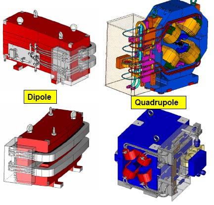
27 ILSF Dipole, Quadrupole & Sextupole shims Dipole Sextupole Quadrupole 27
28 Dipole B = const 0 B(x) Field Quality Calculations central field B = B B B Quadrupole B g0x 0 = Is the field at each point calculated by simulation 0 0 Sextupole B = 1 B x
![B/B0 X[mm] 0-40 -30-20 -10 0 10 20 30 40-0.005-0.01-0.015-0.02-0.](/docs-images/75/72270504/images/29-3.jpg "025 B'/B'0 0.002 0.001 0-30 -20-10 0 10 20 30-0.001-0.002-0.003-0.004-0.")
29 B/B0 X[mm] B'/B' X (mm) 29


30 Saturation test 30


31 Harmonic analysis 31

32 Harmonic analysis & Dynamic Aperture 32


33 3D design:(radia,tosca,mermaid,flux3d ) 3D design is necessary to study : The longitudinal field distribution End effects in the yoke End effects from coils Magnets where the aperture is large compared to the length Unlike 2D, in 3D: all regions with current density have to be modeled completely 33


34 Dipoles: Longitudinal shimming (Chamfering) Rogowsky roll off or angular cut Depth and angle adjusted using 3D codes or measurements Quadrupoles: Angular cut at the end Sextupoles: Usually not chamfered Chamfer should be chosen in such a way that maintain magnetic length constant across the good field region 34


35 ILSF Prototype Magnet I Parameter Value Field 0.5 T Magnetic Length 50 cm Gap height 34 mm Good Field Region ±20mm Parameter Value Field 0.72 T Magnetic Length 155 cm Gap height 32 mm Good Field Region ±18mm H-Type Dipole Magnet C-Type Dipole Magnet 35


36 Parameter Field Gradient Magnetic Length Aperture radius Good Field Region Parameter Sextupole Strength Magnetic Length Aperture radius Good Field Region ILSF Prototype Magnet II Value 23T/m 26 cm 30 mm ±18mm Value 750T/m2 24 cm 36mm ±21mm Quadrupole Magnet Sextupole Magnet 36
37 prototype H-Type dipole magnet Main Objectives: To compare the measurement results with design data. To develop fabrication procedures and techniques. To find if the available low carbon steel is capable of using as magnetic steel. Magnetic specifications of material Magnet specifications Parameter Unit H. Prototype Field-B 0 T 0.5 Gradient-B' T/m - Gap mm 34 Good Field Region mm ±20 B/B - < Mechanical Length mm 500 Chemical components of steel C Si Mn P S 0.03 % 0.01 % 0.24 % % % 37


38 Physical design and main dimensions 2D magnetic design - FEMM 3D magnetic and chamfer design - RADIA Main dimensions 38


39 Electrical and cooling design Parameter Design Value Unit Total ampere-turns per coil 6900 A Operating current 101 A Number of turn per coil 68 - Number of pancakes per coil 2 - Number of turn per pancake 34 - Conductor height 4.05 mm Conductor width 8.66 mm Cooling channel height 1.81 mm Cooling channel width 6.42 mm Copper area mm 2 Specific resistance Ohm mm 2 /m Resistance per coil 0.08 Ohm Current Density 4.33 A/mm 2 Voltage drop per coil 7.79 V Power per coil W Number of water circuit per coil 2 - Water temperature rise 8 C Cooling water speed 1.02 m/s Pressure drop per circuit 10 bar Reynolds number


40 Stacking fixture Winding fixture 40


41 Laser cutting of laminations Washed and dried laminations mixing the two components of resin 41


42 Coating procedure has been done by use of brush, and the packing factor is measured by measuring the length of packed laminations 42


43 43


44 In order to have two ends of the coil in the outer side the coil should wind from the middle for each layers and we need to have even layers 44


45 The machining procedure is done in a way to prevent delamination and to use the common reference point on both yokes to reach to defined tolerances 45


46 46


47 47


48 48

49 ILSF Prototype Quadrupole Magnet 49
50 Magnet specifications Magnetic specifications of material Parameter Unit H. Prototype Gradient-B' T/m 23 Aperture radius mm 30 Good Field Region mm ±18 Magnetic length mm 260 Specification of Quadrupole Magnet B(T) H(A/m) Chemical components of steel C Si Mn P S 0.01 % 1.7 % 0.24 % % - M800 50


51 2D magnetic design - Poisson Main dimensions B'/B'0 Pole profile X (mm) Field tolerances 51


52 Parameter Unit value Parameter Unit value Mechanical Copper area m.0233 length mm Total Ampturns per coil Current density At 6553 A/mm Operating Voltage drop A 96.4 current V 25 Number of Power per - 68 turns per coil magnet KW 2.5 Number of pancakes per coil - No pancakes Number of water circuits - 4 Conductor height Conductor width Cooling channel height Cooling channel width mm 4.05 mm 8.66 mm 1.81 mm 6.42 Electrical and cooling design Water temperature rise Cooling water speed Pressure drop Reynolds number. C 10.0 m/s 1.27 bar

53 Saturation General Drawing 53

54 Laser cutting of laminations & wirecut 54


55 55

56 vacuum Presure impregnation (VPI) Yoke machining assembling Magnetic Measurement 56
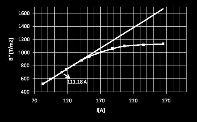
57 y (mm) Theory Design X (mm) 1500 Actual 1300 B'' (T/m2) Sextupole Magnet Prototype B(T) H(A/m) Theory I (A) M800 57


58 Sextupole Design 58

59 Electrical and cooling design Parameter Value total Amp-turns per coil 4902 A Operating current per coil 129 A Number of turns per coil 38 Number of pancakes per coil No pancakes conductor dimensions 6.5 x 6.5 mm 2 Water cooling tube diameter 3.5 mm Copper area mm 2 Current density in copper 3.95 A/mm 2 Voltage drop per magnet V Power per magnet Number of water circuits per magnet Water temperature rise Cooling water speed Pressure drop per coil Reynold No.(should be larger than 1160) Watt C 1.43 m/s 6.22 bar


60 Bending Magnet Prototype Parameter Unit BE1 Bending radius m Deflecting angle Degree Field T 0.72 Gradient field T/m 0 Gap Height mm 32 Magnetic length m 1.55 GFR mm ±18 60


61 Thank you For your attention 61
2 nd ILSF School on Synchrotron Radiation and Its Applications
 2 nd ILSF School on Synchrotron Radiation s Otb October 9-12, 2012 Magnets, Design and fabrication Prepared by: Samira Fatehi,Mohammadreza Khabbazi, Prepared by: Samira Fatehi,Mohammad reza Khabbazi, Mechanic
Accelerators. Table Quadrupole magnet
 Accelerators 2.6 Magnet System 2.6.1 Introduction According to the BEPCII double ring design scheme, a new storage ring will be added in the existing BEPC tunnel. The tasks of the magnet system can be
Basic design and engineering of normalconducting, iron dominated electro magnets
 CERN Accelerator School Specialized Course on Magnets Bruges, Belgium, 16 25 June 2009 Basic design and engineering of normalconducting, iron dominated electro magnets Numerical design Th. Zickler, CERN
Magnet Power Converters and Accelerators
 Magnet Power Converters and Accelerators Neil Marks, DLS/CCLRC, Daresbury Laboratory, Warrington WA4 4AD, U.K. The accelerator lattice. Magnets: dipoles; quadrupole; sextupoles. Contents Magnet excitation
Conventional Magnets for Accelerators
 Conventional Magnets for Accelerators Neil Marks, ASTeC, CCLRC Cockcroft Institute Daresbury Science and Innovation Park Warrington WA4 4AD, U.K. Tel: (44) (0)1925 603191 Fax: (44) (0)1925 603192 E mail:
3.2.2 Magnets. The properties of the quadrupoles, sextupoles and correctors are listed in tables t322_b,_c and _d.
 3.2.2 Magnets The characteristics for the two types of combined function magnets,bd and BF, are listed in table t322_a. Their cross-sections are shown, together with the vacuum chamber, in Figure f322_a.
A Technical Proposal for the Development and Manufacturing of Electromagnets for the TESLA Beam Delivery System
 D.V. Efremov Scientific Research Institute of Electrophysical Apparatus Scientific Technical Center SINTEZ Scientific Technical Center TEMP A Technical Proposal for the Development and Manufacturing of
Conventional Magnets for Accelerators
 Conventional Magnets for Accelerators Neil Marks, ASTeC, Cockcroft Institute, Daresbury, Warrington WA4 4AD, neil.marks@stfc.ac.uk Tel: (44) (0)1925 603191 Fax: (44) (0)1925 603192 Course Philosophy 1.
INTRODUCTION to the DESIGN and FABRICATION of IRON- DOMINATED ACCELERATOR MAGNETS
 INTRODUCTION to the DESIGN and FABRICATION of IRON- DOMINATED ACCELERATOR MAGNETS Cherrill Spencer, Magnet Engineer SLAC National Accelerator Laboratory Menlo Park, California, USA Lecture # 1 of 2 Mexican
Specifications Quality Control Manufacturing Testing. (Part I)
") Quadrupole Bending Insertion Device Specifications Quality Control Manufacturing Testing Septum (Part I) Dieter Einfeld & Montse Pont CELLS / ALBA Spain / Barcelona einfeld@cells.es Sextupole Sextupoles
Quadrupole Bending Insertion Device Specifications Quality Control Manufacturing Testing Septum (Part I) Dieter Einfeld & Montse Pont CELLS / ALBA Spain / Barcelona einfeld@cells.es Sextupole Sextupoles
An improved design method for conventional straight dipole magnets*
 Submitted to Chinese Physics C An improved design method for conventional straight dipole magnets* Ying-shun Zhu( 朱应顺 ) 1;1), Wen Kang( 康文 ) 1,2, Fu-san Chen( 陈福三 ) 1, Wan Chen( 陈宛 ) 1, Xi Wu( 吴锡 ) 1,2,
MAGNETS AND INSERTION DEVICES FOR THE ESRF II
 MAGNETS AND INSERTION DEVICES FOR THE ESRF II OUTLINE Magnetic design R&D and Magnetic measurements IDs & BM sources Summary J. Chavanne G. Lebec C. Benabderrahmane C.Penel On behalf the accelerator upgrade
MAGNETS. Magnet types and performances Part 1
 CERN Accelerator School Bruges, Belgium June 16-25, 2009 MAGNETS Magnet types and performances Part 1 Antoine DAËL CEA, Saclay, france CERN Accelerator School (CAS) Bruges, Belgium June 16-25, 2009 - Antoine
AC Magnet Systems. Ben Shepherd Magnetics and Radiation Sources Group. Daresbury Laboratory.
 AC Magnet Systems Ben Shepherd Magnetics and Radiation Sources Group ASTeC Daresbury Laboratory ben.shepherd@stfc.ac.uk Ben Shepherd, ASTeC Cockcroft Institute: AC Magnets, Autumn 2016 1 Philosophy 1.
The PEP-I1 B-Factory Septum Quadrupole Magnet
 Y The PEP-I1 B-Factory Septum Quadrupole Magnet Johanna M Swan, Arthur R Harvey, Robert H Holmes, C Matthew Kendall, Robert M Yamamoto, and Ted T Yokota (LLNL) Jack T Tanabe and Ross D Schlueter (LBL)
Lattice Cell/Girder Assembly
 SPEAR3 Magnets Jack Tanabe, Nanyang Li, Ann Trautwein, Domenico Dell Orco, Dave Ernst, Zach Wolf (SLAC Magnet Measurements), Catherine L Coq (SLAC Alignment), Jeff Corbett, Bob Hettel (SPEAR3 Physics)
The Booster has three magnet systems for extraction: Kicker Ke, comprising two identical magnets and power supplies Septum Se
 3.2.7 Booster Injection and Extraction 3.2.7.1 Overview The Booster has two magnet systems for injection: Septum Si Kicker Ki The Booster has three magnet systems for extraction: Kicker Ke, comprising
Magnet Buildability Review report : C-Beta Magnets
 Magnet Buildability Review report : C-Beta Magnets Date: December 16 th, 2016 Reviewers: T. Tanabe (chair), M. Anerella, M. Harrison, A. Temnykh and J. Tuozzolo Participants: S. Peggs, K. Smolenski, G.
MAGNETS. Magnet types and performances Part 2
 CERN Accelerator School Bruges, Belgium June 16-25, 2009 MAGNETS Magnet types and performances Part 2 Antoine DAËL CEA, Saclay, France CERN Accelerator School (CAS) Bruges, Belgium June 16-25, 2009 - Antoine
Accelerator Magnet System
 Accelerator Magnet System Friday, 9 July, 010 in Beijing, 16:15 18:15 Ching-Shiang Hwang ( 黃清鄉 ) (cshwang@srrc.gov.tw) gov National Synchrotron Radiation Research Center (NSRRC), Hsinchu Outlines Introduction
Quality control of TPS magnet
 Quality control of TPS magnet Jyh-Chyuan Jan On behalf of magnet group, NSRRC IMMW19, Oct 29, 2015, Hsinchu, Taiwan. Outline Introduction Magnet inspect procedure Mechanical error of magnet Field performance
Design of a Dipole with Longitudinally Variable Field using Permanent Magnets for CLIC DRs
 Design of a Dipole with Longitudinally Variable Field using Permanent Magnets for CLIC DRs M. A. Domínguez, F. Toral (CIEMAT), H. Ghasem, P. S. Papadopoulou, Y. Papaphilippou (CERN) Index 1. Introduction
EUROPEAN ORGANIZATION FOR NUCLEAR RESEARCH Laboratory for Particle Physics. The Bending Magnets For The Proton Transfer Line of CNGS
 EUROPEAN ORGANIZATION FOR NUCLEAR RESEARCH Laboratory for Particle Physics Departmental Report CERN/AT 2006-3 (MEL) The Bending Magnets For The Proton Transfer Line of CNGS K.M. Schirm 1, W. Kalbreier
The initial magnetization curve shows the magnetic flux density that would result when an increasing magnetic field is applied to an initially
 MAGNETIC CIRCUITS The study of magnetic circuits is important in the study of energy systems since the operation of key components such as transformers and rotating machines (DC machines, induction machines,
1. An isolated stationary point charge produces around it. a) An electric field only. b) A magnetic field only. c) Electric as well magnetic fields.
 An electric field only. b) A magnetic field only. c) Electric as well magnetic fields.") 1. An isolated stationary point charge produces around it. a) An electric field only. b) A magnetic field only. c) Electric as well magnetic fields. 2. An isolated moving point charge produces around it.
1. An isolated stationary point charge produces around it. a) An electric field only. b) A magnetic field only. c) Electric as well magnetic fields. 2. An isolated moving point charge produces around it.
Analysis of Coupled Electromagnetic-Thermal Effects in Superconducting Accelerator Magnets
 Analysis of Coupled Electromagnetic-Thermal Effects in Superconducting Accelerator Magnets Egbert Fischer 1, Roman Kurnyshov 2 and Petr Shcherbakov 3 1 Gesellschaft fuer Schwerionenforschung mbh, Darmstadt,
DEVELOPMENT AND PRODUCTION OF SUPERCONDUCTING AND CRYOGENIC EQUIPMENT AND SYSTEMS FOR ACCELERATORS BY IHEP
 I DEVELOPMENT AND PRODUCTION OF SUPERCONDUCTING AND CRYOGENIC EQUIPMENT AND SYSTEMS FOR ACCELERATORS BY IHEP K. Myznikov, A. Ageyev, V. Sytnik, I. Bogdanov, S. Kozub, E. Kashtanov, A. Orlov, V. Sytchev,
N.A.Morozov, H.J.Schreiber * MAGNETIC FIELD CALCULATIONS FOR THE TECHNICAL PROPOSAL OF THE TESLA SPECTROMETER MAGNET. * DESY/Zeuthen, Germany
 N.A.Morozov, H.J.Schreiber * MAGNETIC FIELD CALCULATIONS FOR THE TECHNICAL PROPOSAL OF THE TESLA SPECTROMETER MAGNET * DESY/Zeuthen, Germany Dubna 23 1 Introduction The Tera Electron volts Superconducting
Conventional Magnets for Accelerators Lecture 2
 Conventional Magnets for Accelerators Lecture 2 Ben Shepherd Magneti cs and Radi ati on Sources Group ASTeC Daresbury Laboratory ben.shepherd@stfc.ac.uk Ben Shepherd, ASTeC Cockcroft Institute: Conventional
The ZEPTO project: Tuneable permanent magnets for the next generation of high energy accelerators.
 The ZEPTO project: Tuneable permanent magnets for the next generation of high energy accelerators. Alex Bainbridge, Ben Shepherd, Norbert Collomb, Jim Clarke. STFC Daresbury Laboratory, UK Michele Modena,
Gesellschaft für Schwerionenforschung mbh (GSI), Planckstrasse 1, D Darmstadt, Germany
, Planckstrasse 1, D Darmstadt, Germany") Proceedings of ICEC 22ICMC 2008, edited by HoMyung CHANG et al. c 2009 The Korea Institute of Applied Superconductivity and Cryogenics 9788995713822 Cold electrical connection for FAIR/ SIS100 Kauschke,
Proceedings of ICEC 22ICMC 2008, edited by HoMyung CHANG et al. c 2009 The Korea Institute of Applied Superconductivity and Cryogenics 9788995713822 Cold electrical connection for FAIR/ SIS100 Kauschke,
Conventional Magnets for Accelerators Lecture 1
 Conventional Magnets for Accelerators Lecture 1 Ben Shepherd Magnetics and Radiation Sources Group ASTeC Daresbury Laboratory ben.shepherd@stfc.ac.uk Ben Shepherd, ASTeC Cockcroft Institute: Conventional
The SIS100 Superconducting Magnets
 The SIS100 Superconducting Magnets Anna Mierau Workshop Beam physics for FAIR 2012 May 10 11, 2012 Hotel Haus Schönblick 1. Overview of superconducting beam guiding magnets of the SIS100 - Requirements
Transverse dynamics Selected topics. Erik Adli, University of Oslo, August 2016, v2.21
 Transverse dynamics Selected topics Erik Adli, University of Oslo, August 2016, Erik.Adli@fys.uio.no, v2.21 Dispersion So far, we have studied particles with reference momentum p = p 0. A dipole field
Electromagnetic characterization of big aperture magnet used in particle beam cancer therapy
 Electromagnetic characterization of big aperture magnet used in particle beam cancer therapy Jhonnatan Osorio Moreno M.Pullia, C.Priano Presented at Comsol conference 2012 Milan Milan 10 th October 2012
Water-Cooled Direct Drive Permanent Magnet Motor Design in Consideration of its Efficiency and Structural Strength
 Journal of Magnetics 18(2), 125-129 (2013) ISSN (Print) 1226-1750 ISSN (Online) 2233-6656 http://dx.doi.org/10.4283/jmag.2013.18.2.125 Water-Cooled Direct Drive Permanent Magnet Motor Design in Consideration
Chapter 6: Efficiency and Heating. 9/18/2003 Electromechanical Dynamics 1
 Chapter 6: Efficiency and Heating 9/18/2003 Electromechanical Dynamics 1 Losses As a machine transforms energy from one form to another there is always a certain power loss the loss is expressed as heat,
Chapter 2: Fundamentals of Magnetism. 8/28/2003 Electromechanical Dynamics 1
 Chapter 2: Fundamentals of Magnetism 8/28/2003 Electromechanical Dynamics 1 Magnetic Field Intensity Whenever a magnetic flux, φ, exist in a conductor or component, it is due to the presence of a magnetic
Design Note TRI-DN ARIEL Dogleg Vertical Dipoles EHBT:MBO & EHBT:MB5A. Release: 1 Release Date 2013/12/06
 TRIUMF Document: 104392 Design Note TRI-DN-13-31 ARIEL Dogleg Vertical Dipoles EHBT:MBO & EHBT:MB5A Document Type: Design Note Release: 1 Release Date 2013/12/06 Author(s): Thomas Planche Note: Before
Tools of Particle Physics I Accelerators
 Tools of Particle Physics I Accelerators W.S. Graves July, 2011 MIT W.S. Graves July, 2011 1.Introduction to Accelerator Physics 2.Three Big Machines Large Hadron Collider (LHC) International Linear Collider
January 13, 2005 CBN 05-1 IDEAL WIGGLER 1. A.Mikhailichenko, Cornell University, LEPP, Ithaca NY 14853
 January 1, 005 CBN 05-1 IDEAL WIGGLER 1 A.Mikhailichenko, Cornell University, LEPP, Ithaca NY 1485 Abstract. Described is the wiggler with reduced nonlinear components for usage in the damping ring of
Iranian Light Source Facility (ILSF) Project
 Project") Iranian Light Source Facility (ILSF) Project Hossein Ghasem On behalf of ILSF technical staff School of Particles and Accelerators, IPM 1390 29 28 1 Iranian users requirements Source Energy range Photon
Iranian Light Source Facility (ILSF) Project Hossein Ghasem On behalf of ILSF technical staff School of Particles and Accelerators, IPM 1390 29 28 1 Iranian users requirements Source Energy range Photon
Superconducting Magnets for Future Electron-Ion Collider. Yuhong Zhang Thomas Jefferson National Accelerator Facility, USA
 Superconducting Magnets for Future Electron-Ion Collider Yuhong Zhang Thomas Jefferson National Accelerator Facility, USA Mini-workshop on Accelerator, IAS, HKUST, Hong Kong, January 18-19, 2018 1 Outline
Magnetic Quantities. Magnetic fields are described by drawing flux lines that represent the magnetic field.
 Chapter 7 Magnetic fields are described by drawing flux lines that represent the magnetic field. Where lines are close together, the flux density is higher. Where lines are further apart, the flux density
CONVENTIONAL MAGNETS - I
 CONVENTIONAL MAGNETS - I Neil Marks. Daresbury Laboratory, Warrington, UK. Abstract The design and construction of conventional, steel-cored, direct-current magnets are discussed. Laplace's equation and
Lattice Design for the Taiwan Photon Source (TPS) at NSRRC
 at NSRRC") Lattice Design for the Taiwan Photon Source (TPS) at NSRRC Chin-Cheng Kuo On behalf of the TPS Lattice Design Team Ambient Ground Motion and Civil Engineering for Low Emittance Electron Storage Ring Workshop
Lattice Design for the Taiwan Photon Source (TPS) at NSRRC Chin-Cheng Kuo On behalf of the TPS Lattice Design Team Ambient Ground Motion and Civil Engineering for Low Emittance Electron Storage Ring Workshop
UNIT I INTRODUCTION Part A- Two marks questions
 ROEVER COLLEGE OF ENGINEERING & TECHNOLOGY ELAMBALUR, PERAMBALUR-621220 DEPARTMENT OF ELECTRICAL AND ELECTRONICS ENGINEERING DESIGN OF ELECTRICAL MACHINES UNIT I INTRODUCTION 1. Define specific magnetic
MAGNETIC CIRCUITS. Magnetic Circuits
 Basic Electrical Theory What is a magnetic circuit? To better understand magnetic circuits, a basic understanding of the physical qualities of magnetic circuits will be necessary. EO 1.8 EO 1.9 EO 1.10
4.7.1 Permanent and induced magnetism, magnetic forces and fields. Content Key opportunities for skills development
 4.7 Magnetism and electromagnetism Electromagnetic effects are used in a wide variety of devices. Engineers make use of the fact that a magnet moving in a coil can produce electric current and also that
Lecture 24. April 5 th, Magnetic Circuits & Inductance
 Lecture 24 April 5 th, 2005 Magnetic Circuits & Inductance Reading: Boylestad s Circuit Analysis, 3 rd Canadian Edition Chapter 11.1-11.5, Pages 331-338 Chapter 12.1-12.4, Pages 341-349 Chapter 12.7-12.9,
Lecture Notes ELEC A6
 Lecture Notes ELEC A6 Dr. Ramadan El-Shatshat Magnetic circuit 9/27/2006 Elec-A6 - Electromagnetic Energy Conversion 1 Magnetic Field Concepts Magnetic Fields: Magnetic fields are the fundamental mechanism
PESIT Bangalore South Campus Hosur road, 1km before Electronic City, Bengaluru -100 Department of Electronics & Communication Engineering
 QUESTION PAPER INTERNAL ASSESSMENT TEST 2 Date : /10/2016 Marks: 0 Subject & Code: BASIC ELECTRICAL ENGINEERING -15ELE15 Sec : F,G,H,I,J,K Name of faculty : Dhanashree Bhate, Hema B, Prashanth V Time :
Magnetic Fields
 Magnetic circuits introduction Becomes aware of the similarities between the analysis of magnetic circuits and electric circuits. Develop a clear understanding of the important parameters of a magnetic
Free electron lasers
 Preparation of the concerned sectors for educational and R&D activities related to the Hungarian ELI project Free electron lasers Lecture 2.: Insertion devices Zoltán Tibai János Hebling 1 Outline Introduction
Switched Mode Power Conversion Prof. L. Umanand Department of Electronics System Engineering Indian Institute of Science, Bangalore
 Switched Mode Power Conversion Prof. L. Umanand Department of Electronics System Engineering Indian Institute of Science, Bangalore Lecture - 39 Magnetic Design Good day to all of you. Today, we shall
Physics 610. Adv Particle Physics. April 7, 2014
 Physics 610 Adv Particle Physics April 7, 2014 Accelerators History Two Principles Electrostatic Cockcroft-Walton Van de Graaff and tandem Van de Graaff Transformers Cyclotron Betatron Linear Induction
Design Aspects of High-Field Block-Coil Superconducting Dipole Magnets
 Design Aspects of High-Field Block-Coil Superconducting Dipole Magnets E. I. Sfakianakis August 31, 2006 Abstract Even before the construction of the Large Hadron Collider at CERN is finished, ideas about
Longitudinal dynamics Yannis PAPAPHILIPPOU CERN
 Longitudinal dynamics Yannis PAPAPHILIPPOU CERN United States Particle Accelerator School, University of California - Santa-Cruz, Santa Rosa, CA 14 th 18 th January 2008 1 Outline Methods of acceleration
Study and Characterization of the Limiting Thermal Phenomena in Low-Speed Permanent Magnet Synchronous Generators for Wind Energy
 1 Study and Characterization of the Limiting Thermal Phenomena in Low-Speed Permanent Magnet Synchronous Generators for Wind Energy Mariana Cavique, Student, DEEC/AC Energia, João F.P. Fernandes, LAETA/IDMEC,
Bernhard Holzer, CERN-LHC
 Bernhard Holzer, CERN-LHC * Bernhard Holzer, CERN CAS Prague 2014 x Liouville: in reasonable storage rings area in phase space is constant. A = π*ε=const x ε beam emittance = woozilycity of the particle
Magnetic Measurements
 Magnetic Measurements Neil Marks, DLS/CCLRC, Daresbury Laboratory, Warrington WA4 4AD, U.K. Tel: (44) (0)1925 603191 Fax: (44) (0)1925 603192 Philosophy To cover the possible methods of measuring flux
SPECIFICATIONS for the INJECTION DIPOLES OF THOMX
 SPECIFICATIONS for the INJECTION DIPOLES OF THOMX 29 January 2015 1 INTRODUCTION: THE THOMX PROJECT... 4 2 DESCRIPTION OF THE MAGNETS... 4 2.1 DIPOLE MAGNET... 4 3 SUBJECT OF THE SPECIFICATION... 4 3.1
LOW EMITTANCE MODEL FOR THE ANKA SYNCHROTRON RADIATION SOURCE
 Karlsruhe Institute of Technology (KIT, Karlsruhe, Germany) Budker Institute of Nuclear Physics (BINP, Novosibirsk, Russia) LOW EMITTANCE MODEL FOR THE ANKA SYNCHROTRON RADIATION SOURCE (A.Papash - on
Minimum emittance superbend lattices?
 SLS-TME-TA-2006-0297 3rd January 2007 Minimum emittance superbend lattices? Andreas Streun Paul Scherrer Institut, CH-5232 Villigen PSI, Switzerland Andreas Streun, PSI, Dec.2004 Minimum emittance superbend
Magnetic field and magnetic poles
 Magnetic field and magnetic poles Magnetic Field B is analogically similar to Electric Field E Electric charges (+ and -)are in analogy to magnetic poles(north:n and South:S). Paramagnetism, Diamagnetism,
Lattice Design and Performance for PEP-X Light Source
 Lattice Design and Performance for PEP-X Light Source Yuri Nosochkov SLAC National Accelerator Laboratory With contributions by M-H. Wang, Y. Cai, X. Huang, K. Bane 48th ICFA Advanced Beam Dynamics Workshop
Low Emittance Storage Ring for Light Source. Sukho Kongtawong PHY 554 Fall 2016
 Low Emittance Storage Ring for Light Source Sukho Kongtawong PHY 554 Fall 2016 Content Brightness and emittance Radiative effect and emittance Theory Theoretical Minimum Emittance (TME) cell Double-bend
Electromagnetic Testing (ET)
") Electromagnetic Testing Electromagnetic testing is a general test category that includes Eddy Current testing (ECT), Alternating Current Field Measurement (ACFM) and Remote Field testing. All of these
Electromagnetic Testing Electromagnetic testing is a general test category that includes Eddy Current testing (ECT), Alternating Current Field Measurement (ACFM) and Remote Field testing. All of these
Wigglers for Damping Rings
 Wigglers for Damping Rings S. Guiducci Super B-Factory Meeting Damping time and Emittance Increasing B 2 ds wigglers allows to achieve the short damping times and ultra-low beam emittance needed in Linear
Electromagnetism. Topics Covered in Chapter 14:
 Chapter 14 Electromagnetism Topics Covered in Chapter 14: 14-1: Ampere-turns of Magnetomotive Force (mmf) 14-2: Field Intensity (H) 14-3: B-H Magnetization Curve 14-4: Magnetic Hysteresis 14-5: Magnetic
An Introduction to Particle Accelerators. v short
 An Introduction to Particle Accelerators v1.42 - short LHC FIRST BEAM 10-sep-2008 Introduction Part 1 Particle accelerators for HEP LHC: the world biggest accelerator, both in energy and size (as big as
Introduction to particle accelerators
 Introduction to particle accelerators Walter Scandale CERN - AT department Lecce, 17 June 2006 Introductory remarks Particle accelerators are black boxes producing either flux of particles impinging on
TRANSFORMERS B O O K P G
 TRANSFORMERS B O O K P G. 4 4 4-449 REVIEW The RMS equivalent current is defined as the dc that will provide the same power in the resistor as the ac does on average P average = I 2 RMS R = 1 2 I 0 2 R=
First propositions of a lattice for the future upgrade of SOLEIL. A. Nadji On behalf of the Accelerators and Engineering Division
 First propositions of a lattice for the future upgrade of SOLEIL A. Nadji On behalf of the Accelerators and Engineering Division 1 SOLEIL : A 3 rd generation synchrotron light source 29 beamlines operational
ELECTRO MAGNETIC FIELDS
 SET - 1 1. a) State and explain Gauss law in differential form and also list the limitations of Guess law. b) A square sheet defined by -2 x 2m, -2 y 2m lies in the = -2m plane. The charge density on the
Book Page cgrahamphysics.com Transformers
 Book Page 444-449 Transformers Review The RMS equivalent current is defined as the dc that will provide the same power in the resistor as the ac does on average P average = I 2 RMS R = 1 2 I 0 2 R= V RMS
SMALL-DIAMETER ROTATING COILS FOR FIELD QUALITY MEASUREMENTS IN QUADRUPOLE MAGNETS
 20th IMEKO TC4 International Symposium and 18th International Workshop on ADC Modelling and Testing Research on Electric and Electronic Measurement for XX the Economic IMEKO Upturn TC-4 International Symposium
arxiv: v2 [physics.acc-ph] 27 Oct 2014
![arxiv: v2 [physics.acc-ph] 27 Oct 2014](/thumbs/90/101197166.jpg "arxiv: v2 [physics.acc-ph] 27 Oct 2014") Maxwell s equations for magnets A. Wolski University of Liverpool, Liverpool, UK and the Cockcroft Institute, Daresbury, UK arxiv:1103.0713v2 [physics.acc-ph] 27 Oct 2014 Abstract Magnetostatic fields
Maxwell s equations for magnets A. Wolski University of Liverpool, Liverpool, UK and the Cockcroft Institute, Daresbury, UK arxiv:1103.0713v2 [physics.acc-ph] 27 Oct 2014 Abstract Magnetostatic fields
ROEVER COLLEGE OF ENGINEERING & TECHNOLOGY ELAMBALUR, PERAMBALUR DEPARTMENT OF ELECTRICAL AND ELECTRONICS ENGINEERING ELECTRICAL MACHINES I
 ROEVER COLLEGE OF ENGINEERING & TECHNOLOGY ELAMBALUR, PERAMBALUR-621220 DEPARTMENT OF ELECTRICAL AND ELECTRONICS ENGINEERING ELECTRICAL MACHINES I Unit I Introduction 1. What are the three basic types
EDEXCEL NATIONAL CERTIFICATE/DIPLOMA UNIT 5 - ELECTRICAL AND ELECTRONIC PRINCIPLES NQF LEVEL 3. OUTCOME 3 - MAGNETISM and INDUCTION
 EDEXCEL NATIONAL CERTIFICATE/DIPLOMA UNIT 5 - ELECTRICAL AND ELECTRONIC PRINCIPLES NQF LEVEL 3 OUTCOME 3 - MAGNETISM and INDUCTION 3 Understand the principles and properties of magnetism Magnetic field:
Measurement And Testing. Handling And Storage. Quick Reference Specification Checklist
 Design Guide Contents Introduction Manufacturing Methods Modern Magnet Materials Coatings Units Of Measure Design Considerations Permanent Magnet Stability Physical Characteristics And Machining Of Permanent
3. Synchrotrons. Synchrotron Basics
 1 3. Synchrotrons Synchrotron Basics What you will learn about 2 Overview of a Synchrotron Source Losing & Replenishing Electrons Storage Ring and Magnetic Lattice Synchrotron Radiation Flux, Brilliance
POSITRON EMISSION ISOTOPE PRODUCTION CYCLOTRON AT DLNP JINR (STATUS REPORT)
") Ó³ Ÿ. 2008.. 5, º 7(149).. 74Ä79 ˆ ˆŠ ˆ ˆŠ Š ˆ POSITRON EMISSION ISOTOPE PRODUCTION CYCLOTRON AT DLNP JINR (STATUS REPORT) Yu. G. Alenitsky 1, Yu. N. Denisov, A. F. Chesnov, A. A. Glazov, S. V. Gurskiy,
Ó³ Ÿ. 2008.. 5, º 7(149).. 74Ä79 ˆ ˆŠ ˆ ˆŠ Š ˆ POSITRON EMISSION ISOTOPE PRODUCTION CYCLOTRON AT DLNP JINR (STATUS REPORT) Yu. G. Alenitsky 1, Yu. N. Denisov, A. F. Chesnov, A. A. Glazov, S. V. Gurskiy,
Magnetic Force on a Moving Charge
 Magnetic Force on a Moving Charge Electric charges moving in a magnetic field experience a force due to the magnetic field. Given a charge Q moving with velocity u in a magnetic flux density B, the vector
Accelerators. Lecture V. Oliver Brüning. school/lecture5
 Accelerators Lecture V Oliver Brüning AB/ABP http://bruening.home.cern.ch/bruening/summer school/lecture5 V) LEP, LHC + more LEP LHC Other HEP Projects Future Projects What else? LEP Precision Experiment:
CHAPTER 3 ENERGY EFFICIENT DESIGN OF INDUCTION MOTOR USNG GA
 31 CHAPTER 3 ENERGY EFFICIENT DESIGN OF INDUCTION MOTOR USNG GA 3.1 INTRODUCTION Electric motors consume over half of the electrical energy produced by power stations, almost the three-quarters of the
!"#$%$!&'()$"('*+,-')'+-$#..+/+,0)&,$%.1&&/$ LONGITUDINAL BEAM DYNAMICS
$('*+,-')'+-$#..+/+,0)&,$%.1&&/$ LONGITUDINAL BEAM DYNAMICS") LONGITUDINAL BEAM DYNAMICS Elias Métral BE Department CERN The present transparencies are inherited from Frank Tecker (CERN-BE), who gave this course last year and who inherited them from Roberto Corsini
LONGITUDINAL BEAM DYNAMICS Elias Métral BE Department CERN The present transparencies are inherited from Frank Tecker (CERN-BE), who gave this course last year and who inherited them from Roberto Corsini
NON-SCALING FFAG MAGNET CHALLENGES
 NON-SCALING FFAG MAGNET CHALLENGES N.Marks, ASTeC, STFC, Daresbury Laboratory, and the Cockcroft Institute, Daresbury, U.K. Abstract The BASROC consortium in UK has embarked on the development of non-scaling
CURRENT-CARRYING CONDUCTORS / MOVING CHARGES / CHARGED PARTICLES IN CIRCULAR ORBITS
 PHYSICS A2 UNIT 4 SECTION 4: MAGNETIC FIELDS CURRENT-CARRYING CONDUCTORS / MOVING CHARGES / CHARGED PARTICLES IN CIRCULAR ORBITS # Questions MAGNETIC FLUX DENSITY 1 What is a magnetic field? A region in
Ch. 3. Pulsed and Water Cooled Magnets. T. J. Dolan. Magnetic field calculations
 Ch. 3. Pulsed and Water Cooled Magnets T. J. Dolan Magnetic field calculations Coil forces RLC circuit equations Distribution of J and B Energy storage Switching and transmission Magnetic flux compression
SURVEY AND ALIGNMENT FOR THE SYNCHROTRON LIGHT SOURCE ELETTRA
 I/49 SURVEY AND ALIGNMENT FOR THE SYNCHROTRON LIGHT SOURCE ELETTRA ABSTRACT: F.Wei, A.Bergamo, P.Furlan, J.Grgic, A.Wrulich Sincrotrone Trieste Padriciano 99, 34012 Trieste, Italy ELETTRA is a third generation
DESIGN OF A MODIFIED HALBACH MAGNET FOR THE CBETA PROJECT*
 DESIGN OF A MODIFIED HALBACH MAGNET FOR THE CBETA PROJECT* N. Tsoupas, J.S. Berg, S. Brooks, G. Mahler, F. Méot, S. Peggs, V. Ptitsyn, T. Roser, S. Trabocchi, D. Trbojevic, J. Tuozzolo Brookhaven National
Analytical and numerical computation of the no-load magnetic field in induction motors
 Analytical and numerical computation of the no-load induction motors Dan M. Ionel University of Glasgow, Glasgow, Scotland, UK and Mihai V. Cistelecan Research Institute for Electrical Machines, Bucharest
MAGNETIC MEASUREMENTS OF QUADRUPOLE FOCUSING MAGNETS AT SLAC*
 WAC-PUB-562 1 August 1991 @> MAGNETIC MEASUREMENTS OF QUADRUPOLE FOCUSING MAGNETS AT SLAC* Richard L. Taylor Stanford Linear Accelerator Center, Stanford University, Stanford, CA 94309 and J. J. Pearce
Suppose two uniform bars meet at an abrupt plane and there is a magnetic field induced by an extended core and coil structure off stage as in:
 Class Notes Week of 1/9 /3/017 ENGN1931F The magnetic structures that are central to the design of generators, transformers, motors, inductors, solenoids, etc. can be complex. We need a way to make approximate
FAST-PULSED SUPERCONDUCTING MAGNETS
 FAST-PULSED SUPERCONDUCTING MAGNETS Abstract Up to now only one synchrotron (Nuclotron at JINR, Dubna) has been equipped with fast-pulsed superconducting magnets. The demand for high beam intensities leads
A PRELIMINARY ALIGNMENT PLAN FOR RIA AT MSU
 IWAA2004, CERN, Geneva, 4-7 October 2004 A PRELIMINARY ALIGNMENT PLAN FOR RIA AT MSU D. P. Sanderson, NSCL-MSU, 1 Cyclotron Lab, East Lansing, MI 48824, USA 1. INTRODUCTION The Rare Isotope Accelerator
Lecture 2. Introduction to FEM. What it is? What we are solving? Potential formulation Why? Boundary conditions
 Introduction to FEM What it is? What we are solving? Potential formulation Why? Boundary conditions Lecture 2 Notation Typical notation on the course: Bolded quantities = matrices (A) and vectors (a) Unit
3. Particle accelerators
 3. Particle accelerators 3.1 Relativistic particles 3.2 Electrostatic accelerators 3.3 Ring accelerators Betatron // Cyclotron // Synchrotron 3.4 Linear accelerators 3.5 Collider Van-de-Graaf accelerator
Weak focusing I. mv r. Only on the reference orbit is zero
 Weak focusing I y x F x mv r 2 evb y Only on the reference orbit is zero r R x R(1 x/ R) B y R By x By B0y x B0y 1 x B0 y x R Weak focusing (II) Field index F x mv R 2 x R 1 n Betatron frequency 2 Fx mx