Modeling &Control of Launch Vehicles
|
|
|
- Mae Page
- 6 years ago
- Views:
Transcription


1 Modeling &Control of Launch Vehicles Presented By: M. V. Dhekane Deputy Director Control Guidance & Simulation Entity, VSSC Perspectives In Dynamical Systems & Control
2 Outline ISRO Missions ISRO Launch Vehicles Structure Configuration (PSLV / GSLV / RLV) Propulsion Configuration Aerodynamics Actuation Systems Navigation systems Trajectory Design Guidance & Control Digital Auto-Pilot (DAP) Inputs for design Design problem Design specification Design methodology Control Configuration Launch Vehicle Modelling Input Data Assumptions Rigid Body rotational dynamics Slosh Flexibility
3 Outline RLV-TD (HEX) Mission Mission profile Different phase during descent RLV-TD dynamics Non-linear Control Design parameters Implementation aspect Control design & validation philosophy Post flight analysis Challenges in design
4 ISRO Missions Sun Synchronous Polar Orbit (SSPO) Eastward Missions GTO - Elliptical Orbits(Moon Mission/Mars Mission) Space Capsule Recovery RLV Technology Demonstrator

5 ISRO Launch Vehicles
 Engine Gimbal Control Flex Nozzle")
6 Heat Shield Satellite PS4 stage PS3 Stage PS2 Stage PSLV Configuration Sensors Inertial navigation system Gyros(Attitude) Accelerometers PS1 stage Strapons Actuators SITVC (Secondary injection Thrust Vector Control) Engine Gimbal Control Flex Nozzle control SITVC tank
7 GSLV-MK2 Configuration Definition (4L40+S139)+L37.5+C12.5 Specification Overall length Lift off Mass GTO payload : m : t : 1600 kg Sensors : RESINS at EB, RGP at ½ M Actuators: EGC(L40) EGC(L37.5), CSCE, OSS


8 RLV-TD HEX-1 Vehicle Configuration TDV Experiment : 70 to 0 Mach No. : 6 to 0 Interstage to connect TDV with Booster Booster to achieve required flight condition Base Shroud with Fins To reduce aerodynamic instability To provide control during ascent phase HS9 Booster Diameter : 9T Propellant loading : 1m
9 Propulsion/Configuration SLV-3: Core (S9) + 2 nd stage solid + 3 rd stage solid ASLV: Core (S9) + 2 Strapons (S9) + Solid Upper Stage PSLV: Core S139 (Solid) + 6 Strapons + PS2 (L37.5) + PS3 (Solid) + PS4 (L2.5) GSLV: Core S139 (Solid) + 4 L40 + Cryo (C12) Mk3: RLV: Core S200 (Solid) + 2 L110 + Cryo (C25) Core + TDV (No Propulsion)
10 Aerodynamics SLV-3: ASLV: PSLV: GSLV: Core with Fins Core with 2 Strapons in 1st stage Core alone & (Core + 6 Strapons) Core + 4 liquid Strapons Actuation Systems :Thrust Vector Control SITVC (Secondary Injected Thrust Vector Control) Engine Gimbal Control Flex Nozzle Control Vernier Engine Control Reaction Control System (On-Off Control) Aerodynamic Surfaces
11 Navigation System RESINS: RGP: LAP: Redundant Strap-down Inertial Navigation System Rate Gyro Package Lateral Accelerometer Package Trajectory Design Guidance & Control Guidance : Point Mass Trajectory Maximizing the payload Atmospheric Phase Flight Dynamic Pressure Curve Structural Loads Heating Constraints Range Safety
12 Attitude Dynamics Control: Launch Vehicle (Pitch/Yaw/Roll) Rigid Body Slosh Flexibility Engine dynamics (Actuator + Nozzle) RLV- Longitudinal Dynamics Lateral/ Directional
13 Digital Auto-Pilot (DAP) Launch Vehicle Autopilot is an inner loop of the Navigation, Guidance and Control (NGC) subsystem. Controls the Attitude of the vehicle in Pitch, Yaw and Roll channels from lift-off till end of flight. It ensures the stabilisation of the attitude in the presence of disturbing forces and moments caused by various sources. Steers the vehicle along a desired trajectory, maintaining the structural integrity.
14 Navigation Guidance and Control Loop Target Attitude Guidance + + Law Commands Control Law Actuator Commands Plant Dynamics Attitude Sensing Pos/Velocity Sensing
15 Model of the System to be controlled Plant Inputs for the Design : Rigid body, Flexibility, Slosh Dynamics Actuators : SITVC, EGS, FNC, RCS Sensors : RGP,RESINS, LAP Disturbances Thrust misalignment, CG offset, Differential Thrust, Winds Tracking Commands Generated by Guidance Law Specifications
16 Design Problem Behavior of the output in presence of the disturbance may not be satisfactory Controller has to ensure satisfactory response of the system rejecting the disturbance System will be modeled by using differential equations The controller will process the input signal to achieve satisfactory output. Disturbance (d) command qc Output (q) Controller System Input (d)
17 Design Specifications Primary Specification- Tracing Error < 1 Degree Robustness Specifications Rigid body Aero margin > 6 db Phase margin > 30 Degree Gain margin > 6 db Bending modes Phase Margin > 40 Deg. : Phase Stabilisation Attend. margin > 6 db : Gain Stabilisation Slosh modes Phase margin > 30 Degree
18 Design Methodology Classical Design Technique Tracking Error Specification - Bandwidth / Damping Gain Design- PID Frequency Domain Design Roll off, Notch, Lag-Lead filter Analysis using Root Locus, Bode plot, Nyquist plot
19 Control Configuration Control Power Plant Physical Location / Alignment Control Force / Moment Dynamics Sensors Placement Dynamics Baffles Placement Characteristics
20 Design and development of Autopilot consists following important elements. i). Mathematical model of vehicle dynamics ii). Design to meet specifications iii). On-board implementation of Autopilot Algorithm iv). Validation
21 Block description of system relax improve Performance objective Control hardware Truth model Iterations Design Design model Simulation No OK? Yes Validation Control design process No Yes OK? Clearance for flight


22 LAUNCH VEHICLE MODELLING CONTROL POWER PLANT SENSOR DYNAMICS PLANT MODEL RIGID BODY DYNAMICS STRUCTURES PROPULSION LIQUID SLOSH AERO DYNAMICS
23 Input Data: Launch Vehicle Modelling Plant Model :Mass, Length, Diameter, CG, MI of vehicle Control Power Plant :Actuator model (transfer function), Nozzle mass, length, Inertia Sensor Dynamics Liquid Slosh :Attitude & body rate transfer functions :Pendulum Mass, Length, Distance of pendulum hinge point from CG, Un- damped natural frequency, Damping ratio Structures :Bending mode Frequency, Generalized mass, Mode shape, Mode slope, Damping ratio
24 Input Data: Launch Vehicle Modelling Propulsion Aerodynamic :Thrust :Aerodynamic (Lateral/Side) force coefficients, Center of Pressure Trajectory Atmosphere :Altitude, Mach Number, Inertial velocity :Density Dispersion level :Specified Uncertainty bounds (example: Aero coefficients ±3%, Bending mode frequency ±10% etc.)
25 Launch Vehicle Modeling Assumptions: Time Slice Approach: Time varying mass and inertia properties are frozen over a short period of time (Short Period Dynamics) Small Angle Approximation: Deviations from Reference trajectories are small so that trigonometric nonlinearity, and higher order term s contributions are neglected. Decoupling of Attitude Dynamics: Due to axis symmetry of launch vehicles, Pitch/Yaw/Roll motions are assumed to be decoupled. NOTE: There is significant amount of coupling in Yaw/Roll motion for aircraft. Linear Time Invariant : Non-linearity of actuator/sensors (Dead-zone, slew rate etc.) are neglected at design phase. (All above assumptions lead to LTI systems properties.)
26 Rigid Body Rotational Dynamics θ : Attitude lc : Control moment arm δ : Control variable I : Moment of inertia α : Angle of attack lα : Aerodynamic moment arm L α : (QSCN α) Q : Dynamic Pressure, S Reference area CN α : Aerodynamic Normal Force Coefficient, TC : Controlling Thrust q Iq L l T l sin( d ) Assumptions: q & sin( d ) = d C 2 C C C Iq L l q T l d q () s d() s where, s C C TCl C Ll, I I
27 Rigid Body : Close loop system q C K p s 2 a aasa Actuator Transfer fn d s C 2 Launch Vehicle Transfer fn q 1 K s R ) Block Diagram: Close loop system (Rigid Body Only)
28 Root locus analysis
29
30
31
32 Nyquist + T sec No. of open loop poles in RHP : P = 1 # counter-clockwise encirclement : N =1 Z = P N = 0 (STABLE)
33 Gain Design Method-1: 2 a C Characteristic equation: 1 KP KRs) 0 s 2 aas a s Reference equation : 2 2 ) 2 s ) nns n s as b 2 0 Known variables :,,,,, a a C n n Unknown variables : K, K, a, b p R degree of ch. polynomial : 4 Rigid Body gain : K & K P R a, b : information of rest poles locations
34 Slosh Lateral oscillations of liquids in tank is slosh Modelled by replacing liquid mass with rigid mass and a harmonic oscillator such as spring or pendulum Pendulum parameters are function of tank shape and liquid level

35 Modeling Liquid Slosh The Force & Moments produced by sloshing of the liquid fuel is analyzed by an equivalent Mass and Pendulum Or an equivalent Spring Mass Analogy. Ref: Elements of Control Theory by A. L. Greensite Ref: NASA SP-106
36 Slosh Dynamics L s s w U q L q 2 2 pi ( 2 pi pi pi ) i ( 0 ) ( pi pi ) where, L i w U q pi pi pi pi 0 th : Length of i pendulum th : distance of i pendulum hinge point from body cg th : damping of i Pendulum : Undamped natural Frequencyof : Pendulum angle : Lateral acceleration : Forward inertial velocity : attitude rate i th Pendulum NOTE: Complex Pole-zero pair is introduced in Rigid body dynamics by each Slosh mode.
37 Root Locus (Rigid Body + Slosh) Rigid Body poles: Two poles at origin [K/s 2 ] Actuator : Second order system [w 2 /s 2 +2*z*w*s+w 2 ] Slosh : 6 slosh mode (complex pole zeros pair per slosh mode)
38 Nyquist plot at maximum slosh sensitivity instant : - Rigid Body with Slosh, Actuator, Sensor & delay - Slosh margin 5.5 degree & 8.9 degree
39 Lag-Lead Compensator Bode plot Lag-lead compensator (phase margin improvement)
 ( i) ( i) u q t ( ) i ( ) ( ) th :Generalized")
40 Ref: Elements of Control Theory by A. L. Greensite Bending Mode displacement: Modeling Flexibility Dynamics Where, ( i ) ( i) ( i) u q t ( ) i ( ) ( ) th :Generalized Mode Shape of i Bending mode q ( i ) () t :Generalized Co-ordinate of i th Bending mode
41 Flexibility Dynamics 1. Generalized mode shape is a function of vehicle length and mass distribution etc. Since mass of vehicle is rapidly decreasing, Mode shape is changing w.r.t. time. (Predicted with uncertainty bounds) 2. Generalized Co-ordinate dynamics is represented by second order differential equation. 2 ( ) ( ) ( ) 2 ( ) T ( s 2 i i s [ i ] ) q i c d, i = 1, 2, 3... () i M 3. Flexibility deflection is picked-up by attitude sensor & Flexibledeflection rate is picked-up by rate sensor. where, q q () i R q q R i i () i () i RG () i PG qi () qi () 4. Complex Pole-zero pair is introduced in Rigid body dynamics by each Generalized Co-ordinate.
42 Bending Mode Stabilization Gain Stabilization: Attenuate control loop gain at desired frequency, to ensure stability regardless of control loop phase uncertainty. (Second/Higher BM are usually Gain stabilized) Phase Stabilization: Provide proper phase characteristics at desired frequency to obtain a close loop damping, that is greater than the passive damping. (First/Second BM are usually Gain stabilized) Gain-Phase Stabilization: A Rigid body/flexible mode is said to be gain-phase stabilize if it is close loop stable with finite gain and phase margin.
![Rigid Body + Flexibility Rigid Body poles : Two poles at origin [K/(s 2 - a)] Actuator : Second order system [w 2 /s 2](/docs-images/75/71498995/images/43-1.jpg "+2*z*w*s+w 2 ] Slosh : 3 bending mode (complex pole zeros pair per bending mode) Uncompensated Bode plot Uncompensated")
43 Rigid Body + Flexibility Rigid Body poles : Two poles at origin [K/(s 2 - a)] Actuator : Second order system [w 2 /s 2 +2*z*w*s+w 2 ] Slosh : 3 bending mode (complex pole zeros pair per bending mode) Uncompensated Bode plot Uncompensated Nyquist plot


44 Lag Compensator in Rate path Compensated Nyquist Plot BM1, BM2 are Phase stabilized BM3 Gain stabilized Lag-lead & Roll off filter in forward path
45 HEX-1 MISSION PROFILE 4. Start of Descent Phase h ~ 70 km M ~ Entry Phase Hypersonic Regime h ~ 48 km M ~ Separated Coast Phase HS9 Separation h ~ 32 km M ~ 6 2. Combined Coast Phase 1. Ascent Phase 6. Simulation of Landing maneuvers (Terminal phase) 7. Splashdown in sea Launch from FLP Launch Azimuth : 90º
46 H(m) M Different Phases of RLV during TDV alone Flight Elevon On RCS On Trajectory Data Rudder On < 24 0, Q > 2kPa Phase 1 Phase 2 Phase 3 Coast + Descent x Ascent Nz-Ny Time(sec)
47 Q(kPa) Alpha(deg) Critical Regions of Flight during TDV alone Phase 40 Trajectory Data Phase 1 Phase 2 Phase Time(sec)


48 Aerodynamic instability and Control requirement Higher the aerodynamic instability faster is the divergence: requires quicker Control 16, 0.33 s 0.75, 1.52 s T d V T d V F N W F A F N Reusable Launch Vehicle W PSLV

 GSLV 0.7 1.57 1.92 rad/s (0.31 hz) MK III 3.6 0.")
 2.8 hz (6.5 hz) 1.86 hz (4 hz) 3.06 (4 hz) 10.")
 4.34 hz (> 4 hz) Shuttle 3.4 0.7142 3.68 rad/s (0.")
49 Rigid body and Actuator Bandwidth requirements for various launch vehicles Vehicle μ α Time to double Rigid body BW ( c ) Actuator BW (6 c ) PSLV rad/s (0.47 hz) GSLV rad/s (0.31 hz) MK III rad/s (0.51 hz) RLV 30.8 stable 11.1 rad/s (1.76 hz) 2.8 hz (6.5 hz) 1.86 hz (4 hz) 3.06 (4 hz) hz (6.5hz) TSTO Orbiter rad/s ( hz) 4.34 hz (> 4 hz) Shuttle rad/s ( hz) 3.52 hz (6.5 hz)
50 e e m o e L e D m o mo o o o L o o Lo o D o o Do Iyy QscC mv QsC m QsC q v Iyy QscC Iyy V QscC V g mv QsC mg V mv QsC g m QsC g mv QsC q v d q q d d d sin 1 sin 2 cos 0 cos RLV-TD Pitch Dynamics ) 0 ) 2 )( 2 ( p p p s s s s s s s s Longitudinal Dynamics characteristic equations
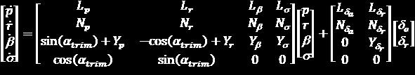
51 State space model: RLV-TD Yaw-Roll Dynamics States: p (roll rate), r (yaw rate), (side-slip angle) and (bank angle) Outputs: (bank rate), (side-slip rate), (side-slip angle) and (bank angle) Inputs: Differential deflection of elevons (d e ) and symmetric deflection of rudders (d r ) State equations Output equations

52
53 Yaw Roll Dynamics coupling Control Design option-1 Control Design option-2
54 Ka Forward Path Gain 2-Dimensional Gain scheduling Phase 2 Alpha channel rigid body Ka Mach 1 0 Q (kpa)
55 Non-Linear Control Integrator limit Rate Control Limit Dead-zone q C K p d q K R s Block Diagram : ON-OFF Control with Dead-zone
56 Design parameters Control Law- Error computation Gain Schedule Filters Integrator Nonlinear control Logics
57 Implementation Aspects Finite Word length Machine Memory and Execution Time Fixed point representation Accuracy and Scaling Overflow problems Transportation and computational delays
58 Control Design & Validation Philosophy Plant (Vehicle + disturbances) Non-failure Cases Failure Cases Act. failure Propulsion fail Nominal Off Nominal(3) Stress(3-6) Over Stressed unrealistic Cases
59 Validation Simulated Input Profile (SIP) OBC In Loop Simulation (OILS) Hardware In Loop Simulation (HLS) Actuator In Loop Simulation (ALS) Flight Test Post flight analysis Disturbance calculationmodel matching Model Update / Design Update

60 Post Flight Analysis
61 Post Flight Analysis
62 Post Flight Analysis
63 Challenges in Design Complexity of the model Robust Design Requirement Fault tolerance SISO to MIMO Unified Design Approach Design Automation Code Automation
64 Acknowledgement I would like to acknowledge my colleagues from Control Design division, CGDG, VSSC for their support in preparation of this course material.
65 Thank You
The Role of Zero Dynamics in Aerospace Systems
 The Role of Zero Dynamics in Aerospace Systems A Case Study in Control of Hypersonic Vehicles Andrea Serrani Department of Electrical and Computer Engineering The Ohio State University Outline q Issues
Chapter 2 Review of Linear and Nonlinear Controller Designs
 Chapter 2 Review of Linear and Nonlinear Controller Designs This Chapter reviews several flight controller designs for unmanned rotorcraft. 1 Flight control systems have been proposed and tested on a wide
CDS 101/110a: Lecture 8-1 Frequency Domain Design
 CDS 11/11a: Lecture 8-1 Frequency Domain Design Richard M. Murray 17 November 28 Goals: Describe canonical control design problem and standard performance measures Show how to use loop shaping to achieve
Today (10/23/01) Today. Reading Assignment: 6.3. Gain/phase margin lead/lag compensator Ref. 6.4, 6.7, 6.10
 Today. Reading Assignment: 6.3. Gain/phase margin lead/lag compensator Ref. 6.4, 6.7, 6.10") Today Today (10/23/01) Gain/phase margin lead/lag compensator Ref. 6.4, 6.7, 6.10 Reading Assignment: 6.3 Last Time In the last lecture, we discussed control design through shaping of the loop gain GK:
Today Today (10/23/01) Gain/phase margin lead/lag compensator Ref. 6.4, 6.7, 6.10 Reading Assignment: 6.3 Last Time In the last lecture, we discussed control design through shaping of the loop gain GK:
Design of Attitude Determination and Control Subsystem
 Design of Attitude Determination and Control Subsystem 1) Control Modes and Requirements Control Modes: Control Modes Explanation 1 ) Spin-Up Mode - Acquisition of Stability through spin-up maneuver -
Stability of CL System
 Stability of CL System Consider an open loop stable system that becomes unstable with large gain: At the point of instability, K( j) G( j) = 1 0dB K( j) G( j) K( j) G( j) K( j) G( j) =± 180 o 180 o Closed
Chapter 1 Lecture 2. Introduction 2. Topics. Chapter-1
 Chapter 1 Lecture 2 Introduction 2 Topics 1.4 Equilibrium of airplane 1.5 Number of equations of motion for airplane in flight 1.5.1 Degrees of freedom 1.5.2 Degrees of freedom for a rigid airplane 1.6
Agile Missile Controller Based on Adaptive Nonlinear Backstepping Control
 Agile Missile Controller Based on Adaptive Nonlinear Backstepping Control Chang-Hun Lee, Tae-Hun Kim and Min-Jea Tahk 3 Korea Advanced Institute of Science and Technology(KAIST), Daejeon, 305-70, Korea
Mech 6091 Flight Control System Course Project. Team Member: Bai, Jing Cui, Yi Wang, Xiaoli
 Mech 6091 Flight Control System Course Project Team Member: Bai, Jing Cui, Yi Wang, Xiaoli Outline 1. Linearization of Nonlinear F-16 Model 2. Longitudinal SAS and Autopilot Design 3. Lateral SAS and Autopilot
1 An Overview and Brief History of Feedback Control 1. 2 Dynamic Models 23. Contents. Preface. xiii
 Contents 1 An Overview and Brief History of Feedback Control 1 A Perspective on Feedback Control 1 Chapter Overview 2 1.1 A Simple Feedback System 3 1.2 A First Analysis of Feedback 6 1.3 Feedback System
MAE 142 Homework #5 Due Friday, March 13, 2009
 MAE 142 Homework #5 Due Friday, March 13, 2009 Please read through the entire homework set before beginning. Also, please label clearly your answers and summarize your findings as concisely as possible.
Localizer Hold Autopilot
 Localizer Hold Autopilot Prepared by A.Kaviyarasu Assistant Professor Department of Aerospace Engineering Madras Institute Of Technology Chromepet, Chennai Localizer hold autopilot is one of the important
Aircraft Stability & Control
 Aircraft Stability & Control Textbook Automatic control of Aircraft and missiles 2 nd Edition by John H Blakelock References Aircraft Dynamics and Automatic Control - McRuler & Ashkenas Aerodynamics, Aeronautics
Department of Aerospace Engineering and Mechanics University of Minnesota Written Preliminary Examination: Control Systems Friday, April 9, 2010
 Department of Aerospace Engineering and Mechanics University of Minnesota Written Preliminary Examination: Control Systems Friday, April 9, 2010 Problem 1: Control of Short Period Dynamics Consider the
CHAPTER 3 PERFORMANCE
 PERFORMANCE 3.1 Introduction The LM-3B performance figures given in this chapter are based on the following assumptions: Launching from XSLC (Xichang Satellite Launch Center, Sichuan Province, China),
Applications Linear Control Design Techniques in Aircraft Control I
 Lecture 29 Applications Linear Control Design Techniques in Aircraft Control I Dr. Radhakant Padhi Asst. Professor Dept. of Aerospace Engineering Indian Institute of Science - Bangalore Topics Brief Review
CHAPTER 3 PERFORMANCE
 PERFORMANCE 3.1 Introduction The LM-3A performance figures given in this chapter are based on the following assumptions: Launching from XSLC (Xichang Satellite Launch Center, Sichuan Province, China),
FLIGHT DYNAMICS. Robert F. Stengel. Princeton University Press Princeton and Oxford
 FLIGHT DYNAMICS Robert F. Stengel Princeton University Press Princeton and Oxford Preface XV Chapter One Introduction 1 1.1 ELEMENTS OF THE AIRPLANE 1 Airframe Components 1 Propulsion Systems 4 1.2 REPRESENTATIVE
GP-B Attitude and Translation Control. John Mester Stanford University
 GP-B Attitude and Translation Control John Mester Stanford University 1 The GP-B Challenge Gyroscope (G) 10 7 times better than best 'modeled' inertial navigation gyros Telescope (T) 10 3 times better
AFRL MACCCS Review. Adaptive Control of the Generic Hypersonic Vehicle
 AFRL MACCCS Review of the Generic Hypersonic Vehicle PI: Active- Laboratory Department of Mechanical Engineering Massachusetts Institute of Technology September 19, 2012, MIT AACL 1/38 Our Team MIT Team
DISTURBANCES MONITORING FROM CONTROLLER STATES
 DISTURBANCES MONITORING FROM CONTROLLER STATES Daniel Alazard Pierre Apkarian SUPAERO, av. Edouard Belin, 3 Toulouse, France - Email : alazard@supaero.fr Mathmatiques pour l Industrie et la Physique, Université
MECH 6091 Flight Control Systems Final Course Project
 MECH 6091 Flight Control Systems Final Course Project F-16 Autopilot Design Lizeth Buendia Rodrigo Lezama Daniel Delgado December 16, 2011 1 AGENDA Theoretical Background F-16 Model and Linearization Controller
Wind Turbine Control
 Wind Turbine Control W. E. Leithead University of Strathclyde, Glasgow Supergen Student Workshop 1 Outline 1. Introduction 2. Control Basics 3. General Control Objectives 4. Constant Speed Pitch Regulated
Problem 1: Ship Path-Following Control System (35%)
") Problem 1: Ship Path-Following Control System (35%) Consider the kinematic equations: Figure 1: NTNU s research vessel, R/V Gunnerus, and Nomoto model: T ṙ + r = Kδ (1) with T = 22.0 s and K = 0.1 s 1.
Problem 1: Ship Path-Following Control System (35%) Consider the kinematic equations: Figure 1: NTNU s research vessel, R/V Gunnerus, and Nomoto model: T ṙ + r = Kδ (1) with T = 22.0 s and K = 0.1 s 1.
Mechatronics Assignment # 1
 Problem # 1 Consider a closed-loop, rotary, speed-control system with a proportional controller K p, as shown below. The inertia of the rotor is J. The damping coefficient B in mechanical systems is usually
A trendsetting Micro-Launcher for Europe
 A trendsetting Micro-Launcher for Europe Farid Gamgami German Aerospace Center (DLR), Space Launcher Systems Analysis (SART) Bremen, Germany Farid.Gamgami@dlr.de ABSTRACT In this paper we analyse a potential,
LUMINARY Memo #214 Revision 1
 Massachusetts Institute of Technology C. S. Draper Laboratory Cambridge, Massachusetts LUMINARY Memo #214 Revision 1 To: Distribution From: Luminary Test Group Date: 6 April 1971 Subject: Level 6 for Luminary
FIBER OPTIC GYRO-BASED ATTITUDE DETERMINATION FOR HIGH- PERFORMANCE TARGET TRACKING
 FIBER OPTIC GYRO-BASED ATTITUDE DETERMINATION FOR HIGH- PERFORMANCE TARGET TRACKING Elias F. Solorzano University of Toronto (Space Flight Laboratory) Toronto, ON (Canada) August 10 th, 2016 30 th AIAA/USU
Positioning Servo Design Example
 Positioning Servo Design Example 1 Goal. The goal in this design example is to design a control system that will be used in a pick-and-place robot to move the link of a robot between two positions. Usually
AMME3500: System Dynamics & Control
 Stefan B. Williams May, 211 AMME35: System Dynamics & Control Assignment 4 Note: This assignment contributes 15% towards your final mark. This assignment is due at 4pm on Monday, May 3 th during Week 13
Aim. Unit abstract. Learning outcomes. QCF level: 6 Credit value: 15
 Unit T23: Flight Dynamics Unit code: J/504/0132 QCF level: 6 Credit value: 15 Aim The aim of this unit is to develop learners understanding of aircraft flight dynamic principles by considering and analysing
ECSE 4962 Control Systems Design. A Brief Tutorial on Control Design
 ECSE 4962 Control Systems Design A Brief Tutorial on Control Design Instructor: Professor John T. Wen TA: Ben Potsaid http://www.cat.rpi.edu/~wen/ecse4962s04/ Don t Wait Until The Last Minute! You got
Aero-Propulsive-Elastic Modeling Using OpenVSP
 Aero-Propulsive-Elastic Modeling Using OpenVSP August 8, 213 Kevin W. Reynolds Intelligent Systems Division, Code TI NASA Ames Research Center Our Introduction To OpenVSP Overview! Motivation and Background!
Multi-layer Flight Control Synthesis and Analysis of a Small-scale UAV Helicopter
 Multi-layer Flight Control Synthesis and Analysis of a Small-scale UAV Helicopter Ali Karimoddini, Guowei Cai, Ben M. Chen, Hai Lin and Tong H. Lee Graduate School for Integrative Sciences and Engineering,
AEROTHERMODYNAMIC ANALYSIS OF INNOVATIVE HYPERSONIC DEPLOYABLE REENTRY CAPSULES. Raffaele Savino University of Naples Federico II
 AEROTHERMODYNAMIC ANALYSIS OF INNOVATIVE HYPERSONIC DEPLOYABLE REENTRY CAPSULES Raffaele Savino University of Naples Federico II Objectives Show the main capabilities of deployable aero-brakes for Earth
Final Exam TTK4190 Guidance and Control
 Trondheim Department of engineering Cybernetics Contact person: Professor Thor I. Fossen Phone: 73 59 43 61 Cell: 91 89 73 61 Email: tif@itk.ntnu.no Final Exam TTK4190 Guidance and Control Friday May 15,
Thrust Vector Control Validation Results for Performance and Stability Robustness Assessments
 Thrust Vector Control Validation Results for Performance and Stability Robustness Assessments M. Valli, D. Spallotta, C. Roux, A. Marcos, A. Mujumdar, P. P. Menon and S. Bennani Abstract Industrial Thrust
SPACE SHUTTLE ROLL MANEUVER
 SPACE SHUTTLE ROLL MANEUVER Instructional Objectives Students will analyze space shuttle schematics and data to: demonstrate graph and schematic interpretation skills; apply integration techniques to evaluate
Flight Dynamics, Simulation, and Control
 Flight Dynamics, Simulation, and Control For Rigid and Flexible Aircraft Ranjan Vepa CRC Press Taylor & Francis Group Boca Raton London New York CRC Press is an imprint of the Taylor & Francis Group, an
A Blade Element Approach to Modeling Aerodynamic Flight of an Insect-scale Robot
 A Blade Element Approach to Modeling Aerodynamic Flight of an Insect-scale Robot Taylor S. Clawson, Sawyer B. Fuller Robert J. Wood, Silvia Ferrari American Control Conference Seattle, WA May 25, 2016
Design of a Heading Autopilot for Mariner Class Ship with Wave Filtering Based on Passive Observer
 Design of a Heading Autopilot for Mariner Class Ship with Wave Filtering Based on Passive Observer 1 Mridul Pande, K K Mangrulkar 1, Aerospace Engg Dept DIAT (DU), Pune Email: 1 mridul_pande000@yahoo.com
CHAPTER 3 PERFORMANCE
 PERFORMANCE The launch performance given in this chapter is based on the following assumptions: The LV system parameters being all nominal values; Mass of the LV adapter and the separation system are included
28TH INTERNATIONAL CONGRESS OF THE AERONAUTICAL SCIENCES
 8 TH INTERNATIONAL CONGRESS OF O THE AERONAUTICAL SCIENCES AUTOPILOT DESIGN FOR AN AGILE MISSILE USING L ADAPTIVE BACKSTEPPING CONTROL Chang-Hun Lee*, Min-Jea Tahk* **, and Byung-Eul Jun*** *KAIST, **KAIST,
AEROSPACE ENGINEERING
 AEROSPACE ENGINEERING Subject Code: AE Course Structure Sections/Units Topics Section A Engineering Mathematics Topics (Core) 1 Linear Algebra 2 Calculus 3 Differential Equations 1 Fourier Series Topics
DEPARTMENT OF AEROSPACE ENGINEERING, IIT MADRAS M.Tech. Curriculum
 DEPARTMENT OF AEROSPACE ENGINEERING, IIT MADRAS M.Tech. Curriculum SEMESTER I AS5010 Engg. Aerodyn. & Flt. Mech. 3 0 0 3 AS5020 Elements of Gas Dyn. & Propln. 3 0 0 3 AS5030 Aircraft and Aerospace Structures
What is flight dynamics? AE540: Flight Dynamics and Control I. What is flight control? Is the study of aircraft motion and its characteristics.
 KING FAHD UNIVERSITY Department of Aerospace Engineering AE540: Flight Dynamics and Control I Instructor Dr. Ayman Hamdy Kassem What is flight dynamics? Is the study of aircraft motion and its characteristics.
Control for. Maarten Steinbuch Dept. Mechanical Engineering Control Systems Technology Group TU/e
 Control for Maarten Steinbuch Dept. Mechanical Engineering Control Systems Technology Group TU/e Motion Systems m F Introduction Timedomain tuning Frequency domain & stability Filters Feedforward Servo-oriented
Generation X. Attitude Control Systems (ACS) Aprille Ericsson Dave Olney Josephine San. July 27, 2000
 Aprille Ericsson Dave Olney Josephine San. July 27, 2000") Generation X Attitude Control Systems (ACS) Aprille Ericsson Dave Olney Josephine San July 27, 2000 ACS Overview Requirements Assumptions Disturbance Torque Assessment Component and Control Mode Recommendations
Generation X Attitude Control Systems (ACS) Aprille Ericsson Dave Olney Josephine San July 27, 2000 ACS Overview Requirements Assumptions Disturbance Torque Assessment Component and Control Mode Recommendations
INNOVATIVE STRATEGY FOR Z9 REENTRY
 INNOVATIVE STRATEGY FOR Z9 REENTRY Gregor Martens*, Elena Vellutini**, Irene Cruciani* *ELV, Corso Garibaldi, 34 Colleferro (Italy) **Aizoon, Viale Città d Europa 681, 144, Roma (Italy) Abstract Large
Adaptive Augmentation of a Fighter Aircraft Autopilot Using a Nonlinear Reference Model
 Proceedings of the EuroGNC 13, 2nd CEAS Specialist Conference on Guidance, Navigation & Control, Delft University of Technology, Delft, The Netherlands, April -12, 13 Adaptive Augmentation of a Fighter
Comparison of Return to Launch Site Options for a Reusable Booster Stage
 Comparison of Return to Launch Site Options for a Reusable Booster Stage Barry Mark Hellman Space System Design Lab (SSDL) School of Aerospace Engineering USAF ASC/XRE barry.hellman@wpafb.af.mil Advisor
Quadrotor Modeling and Control
 16-311 Introduction to Robotics Guest Lecture on Aerial Robotics Quadrotor Modeling and Control Nathan Michael February 05, 2014 Lecture Outline Modeling: Dynamic model from first principles Propeller
FAULT DETECTION AND FAULT TOLERANT APPROACHES WITH AIRCRAFT APPLICATION. Andrés Marcos
 FAULT DETECTION AND FAULT TOLERANT APPROACHES WITH AIRCRAFT APPLICATION 2003 Louisiana Workshop on System Safety Andrés Marcos Dept. Aerospace Engineering and Mechanics, University of Minnesota 28 Feb,
The Interstellar Boundary Explorer (IBEX) Mission Design: A Pegasus Class Mission to a High Energy Orbit
 Mission Design: A Pegasus Class Mission to a High Energy Orbit") The Interstellar Boundary Explorer (IBEX) Mission Design: A Pegasus Class Mission to a High Energy Orbit Ryan Tyler, D.J. McComas, Howard Runge, John Scherrer, Mark Tapley 1 IBEX Science Requirements IBEX
The Interstellar Boundary Explorer (IBEX) Mission Design: A Pegasus Class Mission to a High Energy Orbit Ryan Tyler, D.J. McComas, Howard Runge, John Scherrer, Mark Tapley 1 IBEX Science Requirements IBEX
IAC-13,C4,P,44.p1,x17254 THE DYNAMIC OPERATON OF A HIGH Q EMDRIVE MICROWAVE THRUSTER. Roger Shawyer C.Eng. MIET. FRAeS. SPR Ltd UK
 IAC-13,C4,P,44.p1,x1754 THE DYNAMIC OPERATON OF A HIGH Q EMDRIVE MICROWAVE THRUSTER Roger Shawyer C.Eng. MIET. FRAeS SPR Ltd UK sprltd@emdrive.com ABSTRACT The static operation of an EmDrive microwave
Root Locus Design. MEM 355 Performance Enhancement of Dynamical Systems
 Root Locus Design MEM 355 Performance Enhancement of Dynamical Systems Harry G. Kwatny Department of Mechanical Engineering & Mechanics Drexel University Outline The root locus design method is an iterative,
Turn Performance of an Air-Breathing Hypersonic Vehicle
 Turn Performance of an Air-Breathing Hypersonic Vehicle AIAA Aircraft Flight Mechanics Conference Derek J. Dalle, Sean M. Torrez, James F. Driscoll University of Michigan, Ann Arbor, MI 4809 August 8,
We are IntechOpen, the world s leading publisher of Open Access books Built by scientists, for scientists. International authors and editors
 e are IntechOpen, the world s leading publisher of Open Access books Built by scientists, for scientists 3,8 116, 12M Open access books available International authors and editors Downloads Our authors
Lecture AC-1. Aircraft Dynamics. Copy right 2003 by Jon at h an H ow
 Lecture AC-1 Aircraft Dynamics Copy right 23 by Jon at h an H ow 1 Spring 23 16.61 AC 1 2 Aircraft Dynamics First note that it is possible to develop a very good approximation of a key motion of an aircraft
Robustness Study for Longitudinal and Lateral Dynamics of RLV with Adaptive Backstepping Controller
 Robustness Study for Longitudinal and Lateral Dynamics of RLV with Adaptive Backstepping Controller Anoop P R Department of Electrical and Electronics engineering, TKM college of Engineering,Kollam, India
Fault-Tolerant Control of a Unmanned Aerial Vehicle with Partial Wing Loss
 Preprints of the 19th World Congress The International Federation of Automatic Control Fault-Tolerant Control of a Unmanned Aerial Vehicle with Partial Wing Loss Wiaan Beeton J.A.A. Engelbrecht Stellenbosch
conditions makes precise regulation of angle of attack, angle of sideslip, dynamic pressure, and ight
 Abstract Piloting diculties associated with conducting maneuvers in hypersonic ight are caused in part by the nonintuitive nature of the aircraft response and the stringent constraints anticipated on allowable
Chapter 2 Control Reconfiguration on Deadlocked Gimballed Thrust of Launch Vehicle
 Chapter 2 Control econfiguration on Deadlocked Gimballed Thrust of Launch Vehicle Lei Liu and Yongji Wang Abstract An unprecedented challenge of the new generation launch vehicle control is its four parallel
Dr Ian R. Manchester Dr Ian R. Manchester AMME 3500 : Review
 Week Date Content Notes 1 6 Mar Introduction 2 13 Mar Frequency Domain Modelling 3 20 Mar Transient Performance and the s-plane 4 27 Mar Block Diagrams Assign 1 Due 5 3 Apr Feedback System Characteristics
Minimum Time Ascent Phase Trajectory Optimization using Steepest Descent Method
 IJCTA, 9(39), 2016, pp. 71-76 International Science Press Closed Loop Control of Soft Switched Forward Converter Using Intelligent Controller 71 Minimum Time Ascent Phase Trajectory Optimization using
Pitch Control of Flight System using Dynamic Inversion and PID Controller
 Pitch Control of Flight System using Dynamic Inversion and PID Controller Jisha Shaji Dept. of Electrical &Electronics Engineering Mar Baselios College of Engineering & Technology Thiruvananthapuram, India
Robust Control. 8th class. Spring, 2018 Instructor: Prof. Masayuki Fujita (S5-303B) Tue., 29th May, 2018, 10:45~11:30, S423 Lecture Room
 Tue., 29th May, 2018, 10:45~11:30, S423 Lecture Room") Robust Control Spring, 2018 Instructor: Prof. Masayuki Fujita (S5-303B) 8th class Tue., 29th May, 2018, 10:45~11:30, S423 Lecture Room 1 8. Design Example 8.1 HiMAT: Control (Highly Maneuverable Aircraft
Robust Control Spring, 2018 Instructor: Prof. Masayuki Fujita (S5-303B) 8th class Tue., 29th May, 2018, 10:45~11:30, S423 Lecture Room 1 8. Design Example 8.1 HiMAT: Control (Highly Maneuverable Aircraft
Feedback Control of Linear SISO systems. Process Dynamics and Control
 Feedback Control of Linear SISO systems Process Dynamics and Control 1 Open-Loop Process The study of dynamics was limited to open-loop systems Observe process behavior as a result of specific input signals
(b) A unity feedback system is characterized by the transfer function. Design a suitable compensator to meet the following specifications:
 A unity feedback system is characterized by the transfer function. Design a suitable compensator to meet the following specifications:") 1. (a) The open loop transfer function of a unity feedback control system is given by G(S) = K/S(1+0.1S)(1+S) (i) Determine the value of K so that the resonance peak M r of the system is equal to 1.4.
1. (a) The open loop transfer function of a unity feedback control system is given by G(S) = K/S(1+0.1S)(1+S) (i) Determine the value of K so that the resonance peak M r of the system is equal to 1.4.
Chapter 2. Classical Control System Design. Dutch Institute of Systems and Control
 Chapter 2 Classical Control System Design Overview Ch. 2. 2. Classical control system design Introduction Introduction Steady-state Steady-state errors errors Type Type k k systems systems Integral Integral
Mechanics of Flight. Warren F. Phillips. John Wiley & Sons, Inc. Professor Mechanical and Aerospace Engineering Utah State University WILEY
 Mechanics of Flight Warren F. Phillips Professor Mechanical and Aerospace Engineering Utah State University WILEY John Wiley & Sons, Inc. CONTENTS Preface Acknowledgments xi xiii 1. Overview of Aerodynamics
MEM 355 Performance Enhancement of Dynamical Systems
 MEM 355 Performance Enhancement of Dynamical Systems Frequency Domain Design Intro Harry G. Kwatny Department of Mechanical Engineering & Mechanics Drexel University /5/27 Outline Closed Loop Transfer
SAMPLE SOLUTION TO EXAM in MAS501 Control Systems 2 Autumn 2015
 FACULTY OF ENGINEERING AND SCIENCE SAMPLE SOLUTION TO EXAM in MAS501 Control Systems 2 Autumn 2015 Lecturer: Michael Ruderman Problem 1: Frequency-domain analysis and control design (15 pt) Given is a
Attitude Determination and Control
 Attitude Determination and Control Dan Hegel Director, Advanced Development hegel@bluecanyontech.com 1 Dan Hegel - Intro Director of Advanced Development at Blue Canyon Technologies Advanced mission concepts
MOOC QP Set 2 Principles of Vibration Control
 Section I Section II Section III MOOC QP Set 2 Principles of Vibration Control (TOTAL = 100 marks) : 20 questions x 1 mark/question = 20 marks : 20 questions x 2 marks/question = 40 marks : 8 questions
Frequency Domain System Identification for a Small, Low-Cost, Fixed-Wing UAV
 Frequency Domain System Identification for a Small, Low-Cost, Fixed-Wing UAV Andrei Dorobantu, Austin M. Murch, Bernie Mettler, and Gary J. Balas, Department of Aerospace Engineering & Mechanics University
Robot Dynamics - Rotary Wing UAS: Control of a Quadrotor
 Robot Dynamics Rotary Wing AS: Control of a Quadrotor 5-85- V Marco Hutter, Roland Siegwart and Thomas Stastny Robot Dynamics - Rotary Wing AS: Control of a Quadrotor 7..6 Contents Rotary Wing AS. Introduction
Continuous Differentiation of Complex Systems Applied to a Hypersonic Vehicle
 Continuous of Complex Systems Applied to a Vehicle AIAA Aircraft Flight Mechanics Conference Derek J. Dalle, Sean M. Torrez, James F. Driscoll University of Michigan, Ann Arbor, MI 4819 August 15, 212,
Digital Autoland Control Laws Using Direct Digital Design and Quantitative Feedback Theory
 AIAA Guidance, Navigation, and Control Conference and Exhibit 1-4 August 6, Keystone, Colorado AIAA 6-699 Digital Autoland Control Laws Using Direct Digital Design and Quantitative Feedback Theory Thomas
Fault-Tolerant Flight Control Using One Aerodynamic Control Surface
 Fault-Tolerant Flight Control Using One Aerodynamic Control Surface Raghu Venkataraman and Peter Seiler University of Minnesota, Minneapolis, Minnesota 55455 This paper considers a statically stable unmanned
5.12 The Aerodynamic Assist Trajectories of Vehicles Propelled by Solar Radiation Pressure References...
 1 The Two-Body Problem... 1 1.1 Position of the Problem... 1 1.2 The Conic Sections and Their Geometrical Properties... 12 1.3 The Elliptic Orbits... 20 1.4 The Hyperbolic and Parabolic Trajectories...
Gravity Turn Concept. Curvilinear Coordinate System Gravity Turn Manoeuvre concept Solutions for Constant Pitch Rate
 Gravity Turn Concept Curvilinear Coordinate System Gravity Turn Manoeuvre concept Solutions for Constant Pitch Rate Inclined Motion Concept In reality, vertical motion is used only for a very small part
D(s) G(s) A control system design definition
 G(s) A control system design definition") R E Compensation D(s) U Plant G(s) Y Figure 7. A control system design definition x x x 2 x 2 U 2 s s 7 2 Y Figure 7.2 A block diagram representing Eq. (7.) in control form z U 2 s z Y 4 z 2 s z 2 3 Figure
R E Compensation D(s) U Plant G(s) Y Figure 7. A control system design definition x x x 2 x 2 U 2 s s 7 2 Y Figure 7.2 A block diagram representing Eq. (7.) in control form z U 2 s z Y 4 z 2 s z 2 3 Figure
Robust Nonlinear Design of Three Axes Missile Autopilot via Feedback Linearization
 Robust Nonlinear Design of Three Axes Missile Autopilot via Feedback Linearization Abhijit Das, Ranajit Das and Siddhartha Mukhopadhyay, Amit Patra 1 1 Abstract The nonlinearity and coupling of the missile
CDS 101/110a: Lecture 10-2 Control Systems Implementation
 CDS 101/110a: Lecture 10-2 Control Systems Implementation Richard M. Murray 5 December 2012 Goals Provide an overview of the key principles, concepts and tools from control theory - Classical control -
A Simple Design Approach In Yaw Plane For Two Loop Lateral Autopilots
 A Simple Design Approach In Yaw Plane For Two Loop Lateral Autopilots Jyoti Prasad Singha Thakur 1, Amit Mukhopadhyay Asst. Prof., AEIE, Bankura Unnayani Institute of Engineering, Bankura, West Bengal,
CHAPTER 5 ROBUSTNESS ANALYSIS OF THE CONTROLLER
 114 CHAPTER 5 ROBUSTNESS ANALYSIS OF THE CONTROLLER 5.1 INTRODUCTION Robust control is a branch of control theory that explicitly deals with uncertainty in its approach to controller design. It also refers
Control Systems! Copyright 2017 by Robert Stengel. All rights reserved. For educational use only.
 Control Systems Robert Stengel Robotics and Intelligent Systems MAE 345, Princeton University, 2017 Analog vs. digital systems Continuous- and Discretetime Dynamic Models Frequency Response Transfer Functions
Technology of Rocket
 Technology of Rocket Parts of Rocket There are four major parts of rocket Structural system Propulsion system Guidance system Payload system Structural system The structural system of a rocket includes
Lecture 6 Classical Control Overview IV. Dr. Radhakant Padhi Asst. Professor Dept. of Aerospace Engineering Indian Institute of Science - Bangalore
 Lecture 6 Classical Control Overview IV Dr. Radhakant Padhi Asst. Professor Dept. of Aerospace Engineering Indian Institute of Science - Bangalore Lead Lag Compensator Design Dr. Radhakant Padhi Asst.
Quaternion-Based Tracking Control Law Design For Tracking Mode
 A. M. Elbeltagy Egyptian Armed forces Conference on small satellites. 2016 Logan, Utah, USA Paper objectives Introduction Presentation Agenda Spacecraft combined nonlinear model Proposed RW nonlinear attitude
The loop shaping paradigm. Lecture 7. Loop analysis of feedback systems (2) Essential specifications (2)
 Essential specifications (2)") Lecture 7. Loop analysis of feedback systems (2). Loop shaping 2. Performance limitations The loop shaping paradigm. Estimate performance and robustness of the feedback system from the loop transfer L(jω)
Lecture 7. Loop analysis of feedback systems (2). Loop shaping 2. Performance limitations The loop shaping paradigm. Estimate performance and robustness of the feedback system from the loop transfer L(jω)
PRINCIPLES OF FLIGHT
 1 Considering a positive cambered aerofoil, the pitching moment when Cl=0 is: A infinite B positive (nose-up). C negative (nose-down). D equal to zero. 2 The angle between the aeroplane longitudinal axis
LAUNCH SYSTEMS. Col. John Keesee. 5 September 2003
 LAUNCH SYSTEMS Col. John Keesee 5 September 2003 Outline Launch systems characteristics Launch systems selection process Spacecraft design envelope & environments. Each student will Lesson Objectives Understand
The basic principle to be used in mechanical systems to derive a mathematical model is Newton s law,
 Chapter. DYNAMIC MODELING Understanding the nature of the process to be controlled is a central issue for a control engineer. Thus the engineer must construct a model of the process with whatever information
Chapter 4 The Equations of Motion
 Chapter 4 The Equations of Motion Flight Mechanics and Control AEM 4303 Bérénice Mettler University of Minnesota Feb. 20-27, 2013 (v. 2/26/13) Bérénice Mettler (University of Minnesota) Chapter 4 The Equations
Design and modelling of an airship station holding controller for low cost satellite operations
 AIAA Guidance, Navigation, and Control Conference and Exhibit 15-18 August 25, San Francisco, California AIAA 25-62 Design and modelling of an airship station holding controller for low cost satellite
Semi-Analytical Guidance Algorithm for Fast Retargeting Maneuvers Computation during Planetary Descent and Landing
 ASTRA 2013 - ESA/ESTEC, Noordwijk, the Netherlands Semi-Analytical Guidance Algorithm for Fast Retargeting Maneuvers Computation during Planetary Descent and Landing Michèle LAVAGNA, Paolo LUNGHI Politecnico
Lecture1: Characteristics of Hypersonic Atmosphere
 Module 1: Hypersonic Atmosphere Lecture1: Characteristics of Hypersonic Atmosphere 1.1 Introduction Hypersonic flight has special traits, some of which are seen in every hypersonic flight. Presence of
Automated Estimation of an Aircraft s Center of Gravity Using Static and Dynamic Measurements
 Proceedings of the IMAC-XXVII February 9-, 009 Orlando, Florida USA 009 Society for Experimental Mechanics Inc. Automated Estimation of an Aircraft s Center of Gravity Using Static and Dynamic Measurements