Flow and mass transfer in spacer-filled channels for reverse electrodialysis: a CFD parametrical study
|
|
|
- Virgil Shepherd
- 6 years ago
- Views:
Transcription
1 Cite this article as: Gurreri, L., Tamburini, A., Cipollina, A., Micale, G., Ciofalo, M., Flow and mass transfer in spacer-filled channels for reverse electrodialysis: a CFD parametrical study, Journal of membrane science, 497 (2016) Flow and mass transfer in spacer-filled channels for reverse electrodialysis: a CFD parametrical study L. Gurreri, A. Tamburini*, A. Cipollina, G. Micale, M. Ciofalo Dipartimento di Ingegneria Chimica, Gestionale, Informatica, Meccanica (DICGIM), Università di Palermo (UNIPA) viale delle Scienze Ed.6, Palermo, Italy. * alessandro.tamburini@unipa.it Abstract In Reverse ElectroDialysis (RED) concentration polarization phenomena and pressure drop affect strongly the power output obtainable; therefore the channel geometry has a crucial impact on the system optimization. Both overlapped and woven spacers are commonly commercialised and adopted for RED experiments; the latter exhibit some potential advantages, such as better mixing and lower shadow effect, but they have been poorly investigated in the literature so far. In this work, Computational Fluid Dynamics was used to predict fluid flow and mass transfer in spacer-filled channels for RED applications. A parametric analysis for different spacer geometries was carried out: woven (w) and overlapped (o) spacers with filaments at 90 were simulated, and Reynolds number, pitch to height ratio (l/h) and orientation with respect to the main flow (α = 0 and α = 45 ) were made to vary. The filament arrangement was found to be a crucial feature; for any given pumping power, higher Sherwood numbers were provided by the w-arrangement. The influence of flow attack angle and filament spacing depends on Reynolds number and filament arrangement. Only the configuration w- α45 avoids the presence of poorly mixed zones near the wires. Among the cases investigated here, the configuration that provided the best mixing conditions was w, l/h = 2, α = 45. Keywords Reverse electrodialysis (RED); spacer-filled channel; concentration polarization; mass transfer; CFD. 1
2 1 Introduction and literature review 1.1 Introduction Salinity gradient power is a renewable source of energy arising from the difference of chemical potential between two solutions at different concentrations. Reverse electrodialysis (RED) is a very promising technology, which converts the potential energy of a salinity gradient into electric energy by means of the controlled mixing of the two solutions, flowing in alternate channels separated by selective ion exchange membranes. The cell pair is the repeating unit of the stack, and contains a cationic exchange membrane, a concentrated compartment (e.g. seawater), an anionic exchange membrane and a diluted compartment (e.g. river water). An electric potential difference, due to the chemical potential difference, is established over each membrane, along with a selective transport of cations and anions from each concentrated channel towards the two adjoining diluted ones. This ionic transport is then converted in an electric current supplying an external load by means of reversible redox reactions at the electrodic compartments. More details on the physical principles and on the features of a typical RED system can be found in the literature [1-5]. Pressure drop and polarization phenomena may reduce significantly the efficiency of membrane processes. In fact, the pressure drop is responsible for an energy consumption increase, while the polarization phenomena lead to higher power consumption in non-spontaneous processes and lower driving force in spontaneous processes [6-17]. In RED, hydraulic losses reduce the net power produced, while concentration polarization, i.e. concentration gradients in the boundary layer between the membrane surface and the fluid bulk [18], decreases the gross power: the real electromotive force over the membrane is reduced with respect to the theoretical value (corresponding to the bulk concentrations), and a lower potential difference over the stack is achieved [19]. 2
3 As the flow rate increases, the non-ohmic resistances due to concentration polarization and the streamwise change of the bulk concentration are reduced and thus the gross power Pg increases asymptotically towards a maximum value P max g. On the other hand, higher flow rates lead to increased pressure drop. As a consequence of these opposite effects, the net power density Pn has a maximum value max P n at an optimal flow rate of the feed solutions which depends on the specific configuration of the stack [5, 17, 19-24]. The reduction in power output due to the pumping power Pp (i.e., Pp/Pg) reported in the literature amounts normally to ~10-20% at the flow rate that maximizes the net power. The loss of power with respect to the maximum (asymptotic) value of gross power Pg Pn Pn max max max is much higher; this parameter quantifies the loss with respect to the theoretical maximum achievable, and, from literature data, can be estimated to be ~25-45% [5, 19, 22-25]. The channel configuration is a prominent feature of a RED stack for fluid dynamics and mass transfer, as it affects the flow and the concentration fields within the channel and thus determines distributed pressure drop and concentration polarization. Optimal flow rate and channel configuration should be identified as a compromise solution taking into account different aspects. In this regard, net spacers in either flat sheet or spiral wound modules represent an essential element of RED stacks and many other membrane processes as electrodialysis, reverse osmosis, ultrafiltration, nano-filtration, membrane distillation, etc. A spacer consists of a net of polymeric filaments and can be made with different geometrical features. For example, commercial net spacers can be made of either woven or overlapped wires. Spacers are adopted as mechanical support for the membranes, giving dimensional stability to the channel, but they can also promote fluid mixing thus reducing polarization phenomena. On the other hand, they exhibit the drawback of increased pressure drop, as well as higher electrical resistance (an important feature in RED) and reduced active membrane area due to shadow effects [2, 17, 19, 23, 26]. Therefore the channel geometry optimization 3
4 must take into account mechanical stability, mass transfer (mixing), hydraulic friction and electrical resistance. 1.2 Literature review Several studies can be found in the literature on the characterization of spacer-filled channels, aimed at investigating the effect of spacer geometry (filament spacing, filament diameter, filament arrangement, angle between crossing filaments, flow attack angle) on fluid dynamics features such as flow pattern, recirculation, shear rate distribution, flow regime, pressure drops and mass transport phenomena. Isaacson and Sonin [27] carried out limiting current measurements in an six-channel electrodialyzer (one cell pair, two guard channels and the two electrodic compartments) in order to investigate the spacer performance. Correlations for the Sherwood number (Sh) and the friction factor (f) as functions of the Reynolds number (Re) were found for eddy promoters consisting of cylindrical rods placed in the center of the channel with axes perpendicular to the flow direction. The optimal spacing was about four times channel thickness, and exhibited performance comparable with traditional spacers. Tanaka [28] performed similar limiting current density measurements on anion and cation exchange membranes in a six-channel electrodialyzer. A diamond spacer with overlapped filaments was used in the measuring channel. Results showed that the adopted spacer did not increase the limiting current density, probably because of the dead spaces between the spacer and the membrane; thus a spacer might well have no positive effects on mixing enhancement. Balster et al. [29] tested the performance of different spacer configurations by limiting current density measurements in a six-compartment electrodialysis stack. Conventional non-woven, modified, twisted, and multi-layer spacers were tested. The presence of a spacer clearly enhanced mass transfer with respect to the empty channel. Results showed that twisted rectangular filaments 4
5 can provide better mixing than round filaments due to swirling flows, although the channel performance is also affected by the angle between filaments and the flow attack angle. At the same power number (Pn, proportional to fre 3 ), which expresses in non-dimensional form the power consumption per unit volume, the best multi-layer spacer tested showed a 20% increment in mass transfer with respect to a conventional spacer. Schock and Miquel [30] carried out tests of some commercial spacers, collecting experimental data on pressure drop and mass transfer in spiral wound modules for pressure driven processes. Correlations among the aforementioned dimensionless numbers were obtained, and a performance calculation aiming at optimizing spiral wound elements was addressed. Da Costa et al. [31] analysed in more detail the spacer characteristics developing a semi-empirical model which permits the evaluation of spacer performance (specifically for ultrafiltration). For the case of main flow bisecting the angle between the filaments, this angle was found to be the most important parameter and the value of 90 was found to be the best compromise between high mass transfer coefficients and low pressure drop. In the study of spacer-filled channels for membrane processes, computational fluid dynamics (CFD) is a very effective method for a detailed analysis at small scale and for testing a number of different cases. Schwinge et al. examined flow [32] and mass transfer [33] for cylindrical spacer filaments that were oriented orthogonally to the main flow direction, by two-dimensional CFD modelling. Karode and Kumar [34] applied 3D CFD simulation to several commercial spacers for evaluating pressure drop and the average shear exerted by the fluid on the walls. Li et al. [35] carried out 3D CFD simulations to determine mass transfer coefficients and power consumption of net spacers. The geometric parameters investigated were the mesh length, the angle between the filaments and the flow attack angle. The optimal spacer geometry was that characterized 5
6 by a ratio of filament spacing to channel height of 4, the angle between filaments of 120 and the flow direction bisecting this angle. The same authors validated experimentally these simulations in a subsequent paper [36], obtaining mass transfer coefficients by the limiting current method. This latter paper reports also some experimental results for woven spacers which, to the authors knowledge, are the only data for such spacers reported in the literature. Ranade and Kumar [37] showed that a unit cell approach can be successfully used in CFD simulations, allowing small-scale flow features to be resolved in detail. Also, the contributions of form drag and viscous drag to the overall pressure drop were quantified and spacers with different cross-sections were studied. Santos et al. [38] investigated spacers made of rectangular cross-section filaments by means of (i) direct numerical simulations (DNS) on periodic cells and (ii) experiments, finding that all the fluid flow features were mainly determined by the transverse filaments, while the longitudinal filaments had no significant effect. Koutsou et al. [39] carried out DNS in a periodic unit cell and experimental tests on diamond spacers, by changing the filament spacing and the angle between the crossing filaments (β). As expected, pressure drop tends to decrease by increasing the filament spacing and by reducing β. The same authors published a systematic study (CFD simulations and experiments by limiting current) on mass transfer [40]. Lower values of Sh were obtained as the filament spacing increased, and as β decreased. Also the dependence of Sh on the Schmidt number (Sc) was studied, finding a power law with exponent near 0.4, as in turbulent channel flow. Shakaib et al. [41] studied different spacers, in some of which the transverse and longitudinal filaments were of different diameters. They analysed by CFD the effects of spacer geometry (spacing and thickness of the two sets of filaments, flow attack angle and angle between the filaments) on pressure drop and shear stress. The same authors investigated also mass transfer [42]. A comparison 6
7 between shear stress distribution and mass transfer coefficient distribution was done. The average mass transfer coefficient was found to increase in (i) spacers with increased transverse filament thickness and (ii) spacers with higher angle between filaments which cause a zigzag nature of the flow. For the sake of completeness, it should be mentioned that further papers have been devoted to unsteady flow regimes [43, 44], others have been focused on multi-layer or non-conventional spacers [29, 45-49] and others yet have addressed the CFD modelling of pressure driven membrane processes [50-52] or of membrane distillation [53, 54]. From this review, it can be argued that the literature is still lacking in some fields: (a) the investigation of spacers made by woven filaments. This type of spacers is commercially available and commonly used in the experimental campaigns for RED applications [4, 5, 22, 23, 55, 56] and can offer some potential benefits, such as a better mixing and a lower shadow effect. (b) very low Reynolds numbers. Typical RED channels are very thin (< 500 μm), and usual flow velocity in these channels are not more than a few cm/s. This means that, as a difference from other membrane processes, RED is characterized by very low Re which are not properly investigated in the literature. In this work, 3D-CFD simulations have been carried out, predicting fluid flow and mass transfer in channels with woven and non-woven spacers for RED applications. The specific aim is to provide important insights on the channel geometry optimization in the range of Re of highest interest for RED by means of the characterization of spacers, including some that have poorly investigated so far. 2 CFD modelling The CFD simulations reported in this work are based on the modelling presented in an earlier paper [2]. Therefore, only the main aspects are summarized here. 7
8 2.1 Systems under investigation A net spacer can be made by a variety of geometries on the basis of: filament shape/arrangement, angle between crossing filaments, number of layers, filament spacing, filament size. Other features as deformability and wettability are related to the material. Also, fluid dynamics and mass transfer within a spacer-filled channel depend strongly on the flow attack angle, i.e. the relative orientation of the spacer with respect to the main flow direction. The cases investigated in this work regard diamond-type spacers characterized by filaments of circular cross-section crossing orthogonally and presenting the same diameter d and spacing l. In regards to the wire arrangement, both woven and non-woven (overlapped) spacers are simulated. In this paper, the channel height h was kept fixed and three different values of l were simulated, corresponding to: l/h = 2, 3, 4. These values fall within the range expected in most industrial applications of membrame processes and are those most commonly studied in the literature, thus allowing a comparison between the present simulation results and data from published work. Two different flow attack angles (α) were investigated: the flow direction is either parallel to a filament (α = 0 ) or bisects the angle formed by the filaments (α = 45 ). Figure 1a shows an example of real spacers with overlapped and woven wires crossing at 90, indicating also the filament spacing l and the main flow direction. The parametric analysis was carried out for four values of the Reynolds number (see definition in section 2.4): Re = 1, 4, 16, 64. This represents quite a wide range, since typical values of Re for RED stacks are ~1-10; for a channel 300 μm thick this range corresponds to superficial velocities of cm/s. All cases investigated are reported in Table 1. For convenience, each case studied is identified by a code where the first letter indicates the overlapped (o) or woven (w) arrangement of filaments, and l/h and α are followed by their respective values. 8


 arrows indicate the different flow directions with respect to the spacer, lines indicate the")
9 In the overlapped case with α = 0, the vertical plane parallel to the main flow direction is a geometric symmetry plane. For all other channel configurations, this is a geometric antisymmetry plane. These features are reflected on the flow and concentration fields. Figure 1. Spacer geometries investigated. Left: overlapped; right: woven. (a) arrows indicate the different flow directions with respect to the spacer, lines indicate the projection of the symmetry and antisymmetry planes; (b) Unit Cell geometry; (c) details of the mesh over one half of a cross section of the Unit Cell. 9
10 Table 1. Cases investigated. Case/code Filaments arrangement l/h [mm] α [ ] Re [-] o-l/h2-α0 overlapped 2 0 o-l/h3-α0 overlapped 3 0 o-l/h4-α0 overlapped 4 0 o-l/h2-α45 overlapped 2 45 o-l/h3-α45 overlapped 3 45 o-l/h4-α45 overlapped 4 45 w-l/h2-α0 woven 2 0 w-l/h3-α0 woven 3 0 w-l/h4-α0 woven 4 0 w-l/h2-α45 woven 2 45 w-l/h3-α45 woven 3 45 w-l/h4-α45 woven , 4, 16, 64 In commercial spacers either a compenetration or a deformation of filaments can be observed in the proximity of the contact areas, depending on the manufacturing technique; similarly, the filaments will also be compressed to some degree in the contact areas with the membranes when the spacers are employed in an assembled stack. These aspects were taken into account during the generation of the geometries, as discussed in [2], by assuming (2d-h)/2d = 10%; 70% of this quantity was attributed to the overlap region of the filaments, while 30% to the filament-membrane contacts. These values were obtained via optical microscopy from measurements of commercial spacers (some of them are simulated in [2]) and from data by Da Costa et al. [31]. The fluid simulated is a NaCl aqueous solution at a concentration of 0.5 M, typical of seawater, at 25 C. The physical properties of the solution are [57-59]: density ρ = 1017 kg/m 3, dynamic viscosity μ = Pa s, diffusivity of NaCl in water D = m 2 /s. Seawater is usually employed as the concentrated solution (coupled with river water as the diluted one), but it can also be fed as the diluate coupled with brine, as proposed within the EU-FP7 funded REAPower project [60-63]. 10
11 In this study, the influence of the Schmidt number on mass transfer is not assessed. However, in the case of NaCl solutions this dependence seems not to be important. In fact, the Schmidt numbers for river water (0.017 M), seawater (0.5 M) and brine (5.0 M) are Sc = 583, 622, 888 respectively [57-59]; moreover, the Sherwood number is a weak function of Sc for the low Reynolds numbers considered here [64]. Therefore the Sherwood number depends very little on the specific electrolyte concentration considered. 2.2 Governing equations The computational domain consists of a repetitive periodic unit of the channel (Unit Cell); therefore the governing equations have to be adapted to a periodic domain. Assuming a Newtonian incompressible fluid, the steady-state continuity and momentum transport (Navier-Stokes) equations for three-dimensional flow in a periodic cell are: u 0 (1) 2 u u p u P (2) where u is velocity, ρ is density, μ is dynamic viscosity, p is the periodic component of pressure (whose spatial distribution repeats itself identically in each Unit Cell) and P is a body force per unit volume representing the large-scale component of the driving pressure gradient along the main flow direction (chosen here to be coincident with the z axis) [2, 65]. The choice of steady-state simulations deserves a comment. We performed a relatively accurate transition study only for the woven configuration and l/h = 2. Using the definition of the Reynolds number adopted in the present paper, we found steady-state flow up to Re = 314 (α = 0/90 ) or 273 (α = 45 ), periodic flow for Re = 352 (α = 0/90 ) or 365 (α = 45 ) and chaotic (turbulent) flow for Re 390 (α = 0/90 ) or 466 (α = 45 ). 11
12 For the overlapped geometry, we have not yet performed a study focused on transition to turbulence. However, for l/h = 2 we found steady state flow at Re = 336 (α = 0/90 ) or 316 (α = 45 ), turbulent flow for Re 595 (α = 0/90 ) or 523 (α = 45 ). For l/h=4, at α = 0/90 we found steady state flow at Re = 226 (α = 0/90 ) or 217 (α = 45 ), unsteady flow for Re 330 (α = 0/90 ) or 312 (α = 45 ). For overlapped spacers characterized by l/h = 3-6 and flow attack angle α = 45, Koutsou et al. [39] report the onset of the first flow instabilities at Reynolds numbers of (according to the definition adopted in the present paper). Thus, some discrepancy with our results exists since, under comparable conditions, e.g. l/h = 4, we obtained steady flow up to Re 217. This difference may partly be explained by the different grid resolution adopted in the present study ( volumes, 99% of which hexahedra) and in the cited reference ( volumes). From the rigorous Stefan-Maxwell equation under the assumptions of (i) binary electrolyte and (ii) local electroneutrality, a transport equation, valid also for concentrated solutions, was obtained [2] Cu D C K w (3) corr c where Dcorr D b a M C K z b e c (4) In Eqs. (3) and (4) D is the diffusion coefficient of the electrolyte, a and b are the linear regression parameters of the function ρ = ρ (C) [57], Me is the molar mass of the electrolyte, w is the local value of the velocity component along the main fluid flow direction z, and Kc is the large-scale concentration gradient along z. The quantity C in Eq. (3) is the periodic component of the concentration, such that its spatial distribution repeats itself identically in each Unit Cell. It is introduced in order to impose 12
13 periodic boundary conditions, notwithstanding the streamwise variation of the bulk concentration due to the wall flux, and is defined as The large-scale gradient Kc is C x, y, z C x, y, z Kcz (5) K c J w d IEM ave S V (6) in which d J is the mean value of the electrolyte flux entering the channel at the walls (imposed in IEM the simulation), S is the membrane surface area in a unit cell, wave is the volume-averaged velocity along z in the unit cell and V is the unit cell volume. Note that the transport equation (Eq. (3)) is solved for C ; the real (non periodic) concentration C can be inferred from Eq. (5). Eq. (3) is as a convection-diffusion equation, with a weak non-linearity in the diffusive term and an additional source term -Kcw. Note that the migrative term does not explicitly appears in Eq. (3) because the divergence of the migrative flux is negligible compared to the divergence of the diffusive one and thus does not affect the concentration field. Migrative fluxes themselves are not assumed to be negligible, but are simply superimposed on the diffusive ones without affecting them and are reflected in the boundary conditions of Eq. (3) [2]. 2.3 Computational domain and boundary conditions A single channel was simulated, and an incoming electrolyte flux was imposed through the walls representing the membrane-solution interfaces; therefore, the computational domain represents the dilute channel. The membranes and all phenomena occurring at molecular scale in the electric double layer were not included in the computational domain and thus were not explicitly modelled, but are implicitly accounted for in the boundary conditions. 13
14 Several CFD studies of spacer-filled channels based on the above Unit cell approach can be found in the literature [2, 35, 37-41, 65-68]. This treatment is justified by the fact that the fully developed fields are attained after just a few unit cells [36, 42]. Figure 1b shows examples of the Unit Cells adopted for the two kind of spacer-filled channels simulated in the present work. The choice of the cell size and orientation with respect to the spacer wires is arbitrary for spacers with crossing filaments of equal diameter [67]; therefore, in both spacer-filled channels the minimum periodic unit is chosen. In the case of overlapped wires the choice is also suggested by the possibility of building up an almost completely hexahedral grid. The computational domains were created on the basis of the geometric features and the assumptions on the compenetration/compression of filaments in their contact areas and in the contact areas with the walls, as described in section 2.1. The computational domain for the overlapped configuration was discretized by multi-block grids composed almost entirely by hexahedral elements (less than 1% of the domain volume was meshed by tetrahedra, pyramids and wedges, see Table 2). For the woven configuration, multi-block hybrid grids, although mainly composed by hexahedral elements, had to be created, due to the geometrical complexities. In particular, the zones around the filaments were discretized by tetrahedra, while the remaining part of the computational domain was discretized with hexahedral volumes (see Table 2); pyramids and wedges were necessary at the interfaces between the two parts. In general, hexahedral or hybrid grids provide a greater accuracy and a better convergence to grid-independent results with respect to fully tetrahedral grids [65]. An analysis of the results sensitivity to the computational grid was performed. Various grids were tested for the case of the highest Re investigated and the results obtained were compared, including global quantities (averages on the whole domain) and trends of local quantities on lines perpendicular to the walls. The results show that both velocities and concentrations vary by less than 1% when the number of grid nodes in the wall normal direction increases beyond ~40. Therefore, a mesh size 14
15 corresponding to 51 control volumes in the channel height was chosen for the final simulations. The grids used contain a number of finite volumes ranging from ~ to ~ depending on the specific geometry simulated. The number of finite volumes increases with l/h, and is higher for the woven spacer-filled channels both because the domain volume is twice larger and because it is partly discretized with tetrahedra. Figure 1c reports enlarged details of the meshes in one half of a cross section (at 45 with respect to the filaments). The mesh features are summarized in Table 2. Table 2. Summary of the grids employed. Unit Cell Number of finite volumes in height h Number of finite volumes o-l/h >99 o-l/h >99 o-l/h >99 51 w-l/h w-l/h w-l/h % of domain volume discretized with hexahedra Translational periodicity conditions were imposed on the lateral boundaries of the domain. In each case, the Unit Cell was oriented with respect to the reference frame Oxyz, so that the main flow direction coincided with the z axis. The Unit Cells shown in Figure 1b are oriented so that the flow attack angle is α = 45. The body force per unit volume P in Eq. (2) was set in order to achieve the desired Re (1, 4, 16, 64) on the basis of preliminary simulations. All the other boundaries representing fluid-solid interfaces (fluid-membrane and fluid-filament) are set as walls with no-slip conditions and a Neumann boundary condition for the concentration: a uniform flux is imposed at the upper and lower walls, while the flux is set to zero at the fluid-filament interfaces. Under the assumption of ideal membranes (permselectivity equal to 100%) and transport numbers of ions in the solution equal to 0.5, the diffusive flux at the membranes current density i [2] as d J can be correlated to the IEM 15
16 J d IEM i 0.5 (7) F where F is the Faraday constant. A uniform current density was imposed, as in the previous paper [2]. The functional dependence of Dcorr on the concentration is weak. Also, the variation of the concentration within the domain is relatively limited, due to the low electrolyte fluxes usually involved. For these reasons, the diffusivity varies less than 1%. Since the non-linearity of the transport equation (3) is so weak [2], the Sherwood number is practically independent of the current density; therefore simulating different values of i is not necessary. 2.4 Definitions The hydraulic diameter of the channel is assumed equal to twice the channel thickness, as in the case of an empty (spacer-less) channel of infinite streamwise and spanwise extent d hvoid, 2 h (8) The Reynolds number was calculated in accordance with Re w d mean, void h, void (9) where w is the average velocity along the main flow direction z in a corresponding spacer-less mean, void channel, i.e. the superficial velocity as in previous studies [27, 39, 40]. The Fanning friction factor is defined as f p d (10) z 2 w hvoid, 2 mean, void where Δp/Δz is the mean pressure gradient along the main flow direction and coincides with the module of the source term P in Eq. (2). The pumping power consumption is evaluated by means of the dimensionless power number, defined as [35] 16
17 Pn h SPC fre (11) 3 where SPC is the specific power consumption per unit volume in the corresponding void channel p SPC w mean, void (12) z The local and average mass transfer coefficients are calculated as d J IEM k C Cˆ w b (13) k d J IEM C Cˆ w b (14) where Cw and C w are the local and averaged wall concentration, and C ˆb is the bulk concentration defined as the mass flow weighted average of the concentration on a cross section of the Unit Cell perpendicular to the main flow direction (i.e., a x-y plane on the basis of the present assumptions). Note that k is not the surface average of k. The above definition of k is preferable to that based on the wall average of k, because the local k may diverge at some points making this average meaningless. The local mass transfer coefficient k can be expressed in dimensionless form as a local Sherwood number Sh kd hvoid, (15) Dcorr, ave where Dcorr,ave is the volume average of the diffusivity Dcorr in Eq. (4). Similarly, an average Sherwood number can be defined as Sh kd hvoid, (16) D corr, ave 17
18 Note that Sh is not the surface average of Sh. From dimensional analysis one has that the friction coefficient f and the power number Pn depend on the Reynolds number Re and the geometry of the domain; the Sherwood number Sh depends also on the physical properties of the solution as synthetized by the Schmidt number Sc: f, Pn f, Pn Re, geometry (17) Sh Sh Re, geometry, Sc (18) In the parametric analysis presented in this work the dependence of Sh on Sc is not studied, as mentioned in section 2.1; therefore, by expanding the geometry-related parameters investigated here, one has f, Pn, Sh f, Pn, Sh Re, arrangement, l h, (19) in which arrangement means either overlapped or woven. 2.5 Computational details The governing equations (Eqs. (1), (2), (3)) were discretized and solved in the computational domain with the boundary conditions described in section 2.3 by means of the finite volumes code Ansys -CFX 14. Zero velocity and a homogeneous value of the periodic concentration (0.5 M) were imposed as the initial guess. The High Resolution scheme was used for the advection term discretization. A coupled algorithm was adopted to solve for pressure and velocity. All simulations were run in double precision. The convergence was assumed attained by the criteria of stabilized values of variables at monitor points and normalized residuals lower than A different number of iterations was required, depending on the features of the case simulated. 18
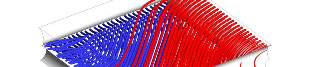
19 3 Results and discussion Simulation results will now be presented and discussed. Section 3.1 reports results relevant to fluid flow, section 3.2 focuses on pressure drop, section 3.3 is devoted to mass transfer, and, finally, section 3.4 compares the present results with CFD and experimental data from the literature. For the sake of brevity, detailed results such as streamlines and Sh maps are shown only for some of the test cases simulated, in order to highlight the effect of some parameters in specific configurations, while the global variables Re, f, Pn and Sh are reported for all the cases investigated. Each case is identified by the code reported in Table Fluid flow The influence of the Reynolds number is shown in Figure 2, which reports in-plane streamlines in the vertical midplane parallel to the flow (see inset) for the case o-l/h3-α0 at different values of Re. Colours indicate the normalized modulus of the velocity, unorm u w ave. Streamlines enter the Unit Cell from below a transverse filament, then fill the whole height of the channel and finally exit the cell from below the subsequent transverse wire. At low Re (1, 4) the presence of creeping flow conditions can be observed, as the flow field is almost symmetric between upstream and downstream with almost no flow separation from the filaments. At higher Re (16, 64) the symmetry feature disappears and flow detachment downstream of the filaments occurs. Below the upper wall, in the proximity of the transverse wires, the streamlines are characterized by stagnation areas at all Re; only at the highest Re (64) a large recirculation cell develops downstream of the transverse filaments, and the straight tract of the streamlines is shortened, i.e. the relative importance of the vertical velocity component increases. Figure 2 refers to the intermediate filament spacing investigated (l/h = 3) and shows that at Re = 64 the vortex fills almost 50% of the upper half of the cell. For l/h = 2, the vortex 19


20 fills the whole upper half of the cell, while, for l/h = 4, its streamwise extent is only ~1/4 th of the cell length. The relevant maps are not shown here for the sake of brevity. Figure 2. Streamlines on the y-z midplane for o-l/h3-α0 at Re = 1, 4, 16, 64. Figure 3 shows the influence of the l/h ratio on the mixing performance of the spacer. It reports 3D streamlines for the same filament arrangement and the other flow attack angle (case o-α45), at Re = 4 and increasing values of l/h. Streamlines starting from the two periodic inlet faces are distinguished by two different colours. As they cross the periodic domain, the fluid threads are divided: some of them remain confined in the same half-channel (upper or lower) where they entered the unit cell, while others switch to the opposite half-channel. The fate of a fluid thread depends mainly on the spanwise location of its entrance point. For the lowest value of l/h about one half of the fluid entering the cell remains in its own half-channel, while for higher values of l/h, an increasing 20
21 part of the fluid switches to the opposite half-channel. These results confirm previous literature findings based on CFD [34, 41]. The influence of the flow rate on the streamlines pattern is shown in Figure 4, which reports 3D streamlines for case o-l/h4-α45, at two values of Re (48 and 90), both much higher than those in Figure 3 but still in the steady-state range. For clarity purposes, only streamlines starting from one of the two periodic inlet faces are shown. It can be observed that, as Re increases, more and more of the streamlines entering the cell close to the upper filament which is located upstream with respect to the main flow direction (to the left in the figure) (i) remain in the upper half of the channel and (ii) follow a spiralling path around an approximately straight axis. The former feature confirms the effect of Re reported by Shakaib et al. [41]; the latter one, lacking in the low-re cases in Figure 3, is similar to what reported by Koutsou et al. [39] for relatively high Reynolds numbers. 21


22 Figure 3. Streamlines for o-α45 at Re = 4 at l/h = 2, 3, 4. 22
23 Figure 4. Streamlines for o-l/h4-α45 at Re = 48 (left) and 90 (right). Arrows indicate the main flow direction. Figure 5 and Figure 6 correspond to Figure 2 and Figure 3, but are for the case of a woven spacer. A markedly different flow field is established in this case. In particular, Figure 5 reports streamlines for the case w-l/h3-α0 at increasing Re. As a difference with Figure 2, 3-D streamlines are shown due to the geometric complexity of the woven configuration. The streamlines start from a vertical plane orthogonal to the flow and cutting a transverse filament, and are represented in different colours according to whether they start from above or below the filament. Along the longitudinal wires, calm regions exist where the fluid flows slowly parallel to them. In the whole remaining part of the channel the fluid trajectories are determined by the curvilinear transversal filaments arranged alternately. If a fluid thread moving along the main flow direction encounters a larger passage area in the upper half of the channel when it crosses a transverse wire, then the same thread will encounter a larger area in the lower half at the next transverse wire, and vice versa. Therefore, the fluid threads located centrally and in the smaller passage area along the spanwise direction tend to remain either in the upper or in the lower half of the channel throughout the cell, while the fluid close to the longitudinal filaments flows alternately above and below the transverse ones. All streamlines exhibit very little spanwise displacement. Very small differences can be observed between different Re. When the obstacles are 23


24 farther apart (i.e. l/h is higher), the curvature of the trajectories is reduced and their rectilinear tracts become longer (figure not shown for brevity). Figure 5. Streamlines for w-l/h3-α0 at Re = 1, 4, 16, 64. When the flow attack angle is made to change (case w-α45) the woven filaments arrangement and their orientation with respect to the main flow direction are such as to give rise to the most complex flow field among the cases investigated here. In Figure 6 the streamlines start from two vertical planes at 45 with the main flow direction, and are visualized in four colours depending on the area from which they start. This configuration is the only one without any stagnant regions, and it forces the 24


25 fluid to move along intricate trajectories with both vertical and lateral displacements. This flow pattern is suitable for achieving a high mixing degree. As l/h increases, the streamlines become less curved, thus a lower mixing is observed. Increasing Re causes the straight tract of the streamlines to become shorter, and the streamlines to follow less the filament boundaries (not shown for brevity). Figure 6. Streamlines for w-α45 at Re = 4 at l/h = 2, 3, 4. 25
26 The effect of the investigated parameters on the flow field can be summarized as follows. In general, the presence of a spacer causes velocity components perpendicular to the main flow direction whose relative importance increases as the Reynolds number increases. The streamlines become more curved on the average as l/h decreases. The filament arrangement (woven vs. overlapped) causes completely different flow fields for both values of α investigated, but woven spacers guarantee a better mixing with respect to overlapped ones. For the overlapped arrangement, the two flow attack angles generate very different flow fields: in both cases (o-α0 and o-α45) the fluid accomplishes movements in the two directions perpendicular to the main flow direction; but in the case o-α0 the lateral motion is confined inside the unit cell by the side filaments parallel to the main flow direction, while in the case o-α45 some fluid threads follow the filament direction and thus remain in their halfchannel (upper or lower), while some move towards the opposite half-channel along zigzag flow paths, with a predominance of the former when l/h decreases and Re increases. For channels with woven filaments the common features are that the flow particles move both up and down and laterally, and that the streamlines present a rectilinear tract at low Re and high l/h. On the other hand, changing α results in some important differences: the case w-α45 is characterized by more displacement in the lateral direction and by the absence of stagnant areas. This is a prominent feature, which makes the case w-α45 the most promising configuration for mixing. 3.2 Pressure drop The Fanning friction factor is reported as a function of the Reynolds number for all the cases investigated in Figure 7. For the empty channel, one has f = 24Re -1. For each geometry the results in Figure 7 can be expressed as 26
27 f n ARe (20) in which, as a first approximation, n = -1. In a more detailed analysis, the value n = -1 holds only at the lowest Re indicating a creeping (self-similar) flow regime. As Re increases, the exponent n of Re deviates slightly from -1. This is due to the slight but increasing inertial effects induced by the spacers: secondary flow appears and the overall flow field loses self-similarity as Re increases. No unsteadiness occurs in the range of Re investigated here. The power number defined by Eq. (11) can be approximated by a power law as Pn m BRe (21) where B = A/8 and m = 3 + n 2. Charts of Pn vs. Re are not shown for the sake of brevity. Table 3 reports the constant A in Eq. (20), evaluated for Re 0, for all the channel configurations. In order to better compare quantitatively the cases investigated, the charts in Figure 8 show f normalized with respect to that in an empty channel (24/Re). Of course, this quantity represents also Pn normalized with respect to that in an empty channel (3Re 2 ). The spacer-filled channels exhibit significant increments (3-20 times) of pressure drops with respect to the spacer-less channel. Also, these increments become higher as Re increases Overlapped o-l/h2-α0 o-l/h4-α0 o-l/h3-α45 empty o-l/h3-α0 o-l/h2-α45 o-l/h4-α Woven w-l/h2-α0 w-l/h4-α0 w-l/h3-α45 empty w-l/h3-α0 w-l/h2-α45 w-l/h4-α45 f [-] 10 f [-] Re[-] Re [-] 27
28 Figure 7. Friction factor as a function of Reynolds number for all cases simulated. Table 3. Constant A in Eq. (20) for Re 0. o / w l/h α A for Re 0 [-] o o o o o o w w w w w w The flow attack angle α effect is irrelevant at these Re [2], despite it influences deeply the flow field. The only exception is the case of the woven arrangement along with the minimum filament spacing (w-l/h2), which reveals a small effect of α at the highest Re. The filament spacing l/h has remarkable effects, especially for the w-arrangement. Of course, as l/h increases, pressure drop is reduced and approaches that of the empty channel. Figure 8 reports also the percent relative increment of pressure loss and pumping power from l/h4 to l/h3 and from l/h4 to l/h2. It is evident that l/h is a crucial parameter in determining the pumping power consumption. Also the filaments arrangement has a significant influence. The w-arrangement requires a pressure drop larger on average by 106%, 67% and 54% with respect to the o-arrangement, for l/h = 2, 3, 4 respectively. Thus, it is worth noting that (i) passing from overlapped to woven filaments, the 28
29 hydraulic loss increases dramatically, and (ii) the arrangement has a larger influence as the pitch to height ratio decreases. The effect of the filament arrangement is not surprising. In fact, woven wires offer a larger fluidsolid interface for friction. Moreover, they allow the fluid to flow both above and below the obstacle, while overlapped ones significantly interact with the fluid only by one side. Finally, the components of velocity orthogonal to the main flow direction are more important, thus increasing mixing but also near wall velocity gradients and thus friction Overlapped o-l/h2-α0 o-l/h3-α0 o-l/h4-α0 o-l/h2-α45 o-l/h3-α45 o-l/h4-α Woven w-l/h2-α0 w-l/h4-α0 w-l/h3-α45 w-l/h3-α0 w-l/h2-α45 w-l/h4-α45 f/(24/re) [-] % f/(24/re) [-] % 46-48% 33-39% Re[-] Re [-] Figure 8. Friction factor normalized by that pertaining to an empty channel (24/Re) as a function of the Reynolds number for all cases simulated. Note that this quantity is also the power number normalized by that of the empty channel. 3.3 Mass transfer All the simulations in this paper are run by imposing the bulk concentration C ˆb and the mass flux at the walls (coinciding with the diffusive component Since d J IEM since there is no convection at the walls). d J IEM =D C/ y, where D is diffusivity, C is concentration and y is the coordinate normal to the 29
30 wall, this implies that the near-wall slope of the C profile is the same in all cases, while the concentration at the walls Cw is computed as a result of the simulation. The effect of Reynolds number and spacer configuration is to alter the C profile in the whole channel, thus affecting the wall-to-bulk concentration difference. Since the local mass transfer coefficient is defined as k= J d IEM /(Cw - C ˆb ), an increase, say, of the Reynolds number causes a reduction of Cw - C ˆb and thus an increase in k (i.e., in the Sherwood number). As an example of these effects see Figure 9 in one of our previous papers [2], which compares the wall-to-wall concentration profiles computed along a straight cross-stream line for a woven spacer and increasing Re Influence of filaments arrangement and flow attack angle In Figure 9 the distribution of the normalized local Sherwood number on the walls is reported for different filaments arrangements and flow attack angles at a fixed value of l/h (3) and Re (4). For each case, the maps for both walls are shown from the same viewpoint. Of course, the symmetry/antisymmetry features of the geometry hold also for the concentration field. Therefore the maps on the upper and lower walls are exactly antisymmetric (i.e. are identical apart from reflections and rotations) for all cases, apart from o-α0: in this case each of the two maps is symmetric about the main flow direction, but the two maps differ from each other. The same scale was used for all configurations in order to make comparisons easier. Figure 9 shows that the spacer filaments arrangement and the spacer orientation have a strong impact on the Sh distribution. Note the presence of areas with low values of Sh (thus high concentration polarization) in correspondence of calm regions with low fluid velocities near the filaments. These areas, detrimental for mixing, are located in the proximity of the longitudinal wires for the case w-α0 and near both filament layers for the overlapped spacer (o-α0 and o-α45). The 30


31 configuration w-α45 is the only one able to avoid this disadvantageous effect of the filaments. This feature, combined with a complex flow field with significant convective motions orthogonal to the walls, favours mixing thus giving rise to the highest Sh for the case w-α45. 31
32 Figure 9. Maps of the normalized local Sherwood number on the upper and lower walls for the two filaments arrangement (o and w) and the two flow attack angles (α0 and α45) at l/h3 and Re = Influence of Reynolds number and pitch to height ratio Figure 10 reports the distribution of the normalized local Sherwood number on the upper wall for the case w-α45 by varying Re and l/h. In particular, the configuration chosen is that which offers the best performance, as it was discussed above. To make comparisons easier, the scale is the same for all cases and is also the same as that adopted in the previous Figure 9. The maps reported in the figure are similar in shape, thus indicating that the two parameters analysed here affect the distribution of the Sherwood number less than w / o and α; in fact, similar location of minima and maxima can be observed among the various cases of Figure 10. On the other hand, the Sh distribution is less homogeneous as Sh increases. As expected, as Re increases, a mixing enhancement is obtained, i.e. Sh increases, due to the increasing convective motions orthogonal to the walls. However, Sh increases only as ~Re 0.5. Figure 10 shows also that an increase of Sh is obtained as the pitch decreases. This effect confirms what was inferred from the analysis of the flow field (e.g. streamlines in Figure 6). 32


33 Figure 10. Maps of the normalized local Sherwood number on the upper wall for the case w-α45 by varying Re and l/h. Figure 11 reports Sh as a function of Re for all cases simulated. The charts show also Sh for fully developed laminar flow within an empty channel of infinite streamwise and spanwise extension with uniform mass flux at the walls ( Sh 8.23). It is evident that the presence of a spacer strongly affects mass transfer phenomena. At very low Re, mixing is not favoured in the spacer-filled channels, due to the calm regions caused by the filaments which are detrimental for mass transfer, especially for α0. 33
34 As a consequence, the spacer-filled channels can exhibit Sh even lower than the empty channel as also observed for different cases by Fimbres-Weihs and Wiley [69]. On the other hand, as Re increases, much higher Sh values are attained; in fact increased inertial fluid flow phenomena come into play, thus causing a mixing enhancement. Each channel configuration is characterized by a specific cut-off value of Re beyond which mass transfer performance is better than that of the empty channel. In the case w-α45 this occurs at Re close to 0, in the other cases at higher values, but always at Re lower than ~7. In regards to the influence of the parameters, the filament spacing has a clear effect for all Re only in the case w-α45: in particular, Sh decreases as l/h increases. For w-α0 this occurs only at the highest Reynolds numbers; for the o-arrangement the dependence of Sh on l/h is not significant. The flow attack angle plays an important role in determining mass transfer for the w-arrangement, although it has very slight effects on pressure drop: for all Re and l/h, a mixing promotion is achieved when the fluid bisects the angle between crossing filaments, i.e. the configuration w-α45 exhibits Sh higher than w-α0. On the other hand, the discrepancies between the Sherwood numbers obtained for the two values of α in woven spacer-filled channels are lower at high Re. For the o-arrangement, the effect of α is small and varies with Re. The filament arrangement is shown to be a key parameter for mass transport. Results show that the w-arrangement allows a mixing enhancement (higher Sh ) with respect to the o-arrangement, with the exception of very low Re and α = 0. For any given Re the configuration that guarantees the best mixing conditions is w-l/h2-α45. 34
CFD Simulation of Mass Transfer Phenomena in Spacer Filled Channels for Reverse Electrodialysis Applications
 A publication of 1879 CHEMICAL ENGINEERING TRANSACTIONS VOL. 32, 213 Chief Editors: Sauro Pierucci, Jiří J. Klemeš Copyright 213, AIDIC Servizi S.r.l., ISBN 978-88-9568-23-5; ISSN 1974-9791 The Italian
COMPUTATIONAL FLUID DYNAMICS OF REVERSE ELECTRODIALYSIS SYSTEMS
 Dottorato in Ingegneria Chimica, Gestionale, Meccanica, Informatica Indirizzo Ingegneria Chimica e dei Materiali Dipartimento di Ingegneria Chimica, Gestionale, Meccanica, Informatica Settore Scientifico
CFD STUDY OF MASS TRANSFER IN SPACER FILLED MEMBRANE MODULE
 GANIT J. Bangladesh Math. Soc. (ISSN 1606-3694) 31 (2011) 33-41 CFD STUDY OF MASS TRANSFER IN SPACER FILLED MEMBRANE MODULE Sharmina Hussain Department of Mathematics and Natural Science BRAC University,
ON SOME ISSUES IN THE COMPUTATIONAL MODELLING OF SPACER-FILLED CHANNELS FOR MEMBRANE DISTILLATION
 Post-print of the article published on: Desalination (2017) Please cite this article as: M. La Cerva, M. Ciofalo, L. Gurreri, A. Tamburini, A. Cipollina, G. Micale, On some issues in the computational
Principles of Convection
 Principles of Convection Point Conduction & convection are similar both require the presence of a material medium. But convection requires the presence of fluid motion. Heat transfer through the: Solid
Helical Coil Flow: a Case Study
 Excerpt from the Proceedings of the COMSOL Conference 2009 Milan Helical Coil Flow: a Case Study Marco Cozzini Renewable Energies and Environmental Technologies (REET) Research Unit, Fondazione Bruno Kessler
Laminar flow heat transfer studies in a twisted square duct for constant wall heat flux boundary condition
 Sādhanā Vol. 40, Part 2, April 2015, pp. 467 485. c Indian Academy of Sciences Laminar flow heat transfer studies in a twisted square duct for constant wall heat flux boundary condition RAMBIR BHADOURIYA,
Turbulent Boundary Layers & Turbulence Models. Lecture 09
 Turbulent Boundary Layers & Turbulence Models Lecture 09 The turbulent boundary layer In turbulent flow, the boundary layer is defined as the thin region on the surface of a body in which viscous effects
Convective Mass Transfer
 Convective Mass Transfer Definition of convective mass transfer: The transport of material between a boundary surface and a moving fluid or between two immiscible moving fluids separated by a mobile interface
UNIT II CONVECTION HEAT TRANSFER
 UNIT II CONVECTION HEAT TRANSFER Convection is the mode of heat transfer between a surface and a fluid moving over it. The energy transfer in convection is predominately due to the bulk motion of the fluid
CHAPTER 7 NUMERICAL MODELLING OF A SPIRAL HEAT EXCHANGER USING CFD TECHNIQUE
 CHAPTER 7 NUMERICAL MODELLING OF A SPIRAL HEAT EXCHANGER USING CFD TECHNIQUE In this chapter, the governing equations for the proposed numerical model with discretisation methods are presented. Spiral
International Journal of Scientific & Engineering Research, Volume 6, Issue 5, May ISSN
 International Journal of Scientific & Engineering Research, Volume 6, Issue 5, May-2015 28 CFD BASED HEAT TRANSFER ANALYSIS OF SOLAR AIR HEATER DUCT PROVIDED WITH ARTIFICIAL ROUGHNESS Vivek Rao, Dr. Ajay
Fluid Dynamics Exercises and questions for the course
 Fluid Dynamics Exercises and questions for the course January 15, 2014 A two dimensional flow field characterised by the following velocity components in polar coordinates is called a free vortex: u r
COMPUTATIONAL FLUID DYNAMICS ANALYSIS OF A V-RIB WITH GAP ROUGHENED SOLAR AIR HEATER
 THERMAL SCIENCE: Year 2018, Vol. 22, No. 2, pp. 963-972 963 COMPUTATIONAL FLUID DYNAMICS ANALYSIS OF A V-RIB WITH GAP ROUGHENED SOLAR AIR HEATER by Jitesh RANA, Anshuman SILORI, Rajesh MAITHANI *, and
ENERGY PERFORMANCE IMPROVEMENT, FLOW BEHAVIOR AND HEAT TRANSFER INVESTIGATION IN A CIRCULAR TUBE WITH V-DOWNSTREAM DISCRETE BAFFLES
 Journal of Mathematics and Statistics 9 (4): 339-348, 2013 ISSN: 1549-3644 2013 doi:10.3844/jmssp.2013.339.348 Published Online 9 (4) 2013 (http://www.thescipub.com/jmss.toc) ENERGY PERFORMANCE IMPROVEMENT,
Unit operations of chemical engineering
 1 Unit operations of chemical engineering Fourth year Chemical Engineering Department College of Engineering AL-Qadesyia University Lecturer: 2 3 Syllabus 1) Boundary layer theory 2) Transfer of heat,
Active Control of Separated Cascade Flow
 Chapter 5 Active Control of Separated Cascade Flow In this chapter, the possibility of active control using a synthetic jet applied to an unconventional axial stator-rotor arrangement is investigated.
Chapter 8: Flow in Pipes
 Objectives 1. Have a deeper understanding of laminar and turbulent flow in pipes and the analysis of fully developed flow 2. Calculate the major and minor losses associated with pipe flow in piping networks
This section develops numerically and analytically the geometric optimisation of
 7 CHAPTER 7: MATHEMATICAL OPTIMISATION OF LAMINAR-FORCED CONVECTION HEAT TRANSFER THROUGH A VASCULARISED SOLID WITH COOLING CHANNELS 5 7.1. INTRODUCTION This section develops numerically and analytically
Numerical analysis of fluid flow and heat transfer in 2D sinusoidal wavy channel
 Numerical analysis of fluid flow and heat transfer in 2D sinusoidal wavy channel Arunanshu Chakravarty 1* 1 CTU in Prague, Faculty of Mechanical Engineering, Department of Process Engineering,Technická
Basic Fluid Mechanics
 Basic Fluid Mechanics Chapter 6A: Internal Incompressible Viscous Flow 4/16/2018 C6A: Internal Incompressible Viscous Flow 1 6.1 Introduction For the present chapter we will limit our study to incompressible
Friction Factors and Drag Coefficients
 Levicky 1 Friction Factors and Drag Coefficients Several equations that we have seen have included terms to represent dissipation of energy due to the viscous nature of fluid flow. For example, in the
CONVECTIVE HEAT TRANSFER
 CONVECTIVE HEAT TRANSFER Mohammad Goharkhah Department of Mechanical Engineering, Sahand Unversity of Technology, Tabriz, Iran CHAPTER 4 HEAT TRANSFER IN CHANNEL FLOW BASIC CONCEPTS BASIC CONCEPTS Laminar
Chapter 2 Mass Transfer Coefficient
 Chapter 2 Mass Transfer Coefficient 2.1 Introduction The analysis reported in the previous chapter allows to describe the concentration profile and the mass fluxes of components in a mixture by solving
Cooling of a multi-chip power module
 Cooling of a multi-chip power module G. CAMMARAA, G. PERONE Department of Industrial Engineering University of Catania Viale A. Doria 6, 953 Catania IALY gcamma@dii.unict.it, gpetrone@dii.unict.it Abstract:
Supplementary Information for Engineering and Analysis of Surface Interactions in a Microfluidic Herringbone Micromixer
 Supplementary Information for Engineering and Analysis of Surface Interactions in a Microfluidic Herringbone Micromixer Thomas P. Forbes and Jason G. Kralj National Institute of Standards and Technology,
Entropic Evaluation of Dean Flow Micromixers
 COMSOL Conference, Boston, 2013 Brian Vyhnalek, Petru S. Fodor and Miron Kaufman Physics Department Cleveland State University Entropic Evaluation of Dean Flow Micromixers ABSTRACT We study the use of
Department of Mechanical Engineering
 Department of Mechanical Engineering AMEE401 / AUTO400 Aerodynamics Instructor: Marios M. Fyrillas Email: eng.fm@fit.ac.cy HOMEWORK ASSIGNMENT #2 QUESTION 1 Clearly there are two mechanisms responsible
Boundary-Layer Theory
 Hermann Schlichting Klaus Gersten Boundary-Layer Theory With contributions from Egon Krause and Herbert Oertel Jr. Translated by Katherine Mayes 8th Revised and Enlarged Edition With 287 Figures and 22
 UNIT IV BOUNDARY LAYER AND FLOW THROUGH PIPES Definition of boundary layer Thickness and classification Displacement and momentum thickness Development of laminar and turbulent flows in circular pipes
7. Basics of Turbulent Flow Figure 1.
 1 7. Basics of Turbulent Flow Whether a flow is laminar or turbulent depends of the relative importance of fluid friction (viscosity) and flow inertia. The ratio of inertial to viscous forces is the Reynolds
Numerical simulation of fluid flow in a monolithic exchanger related to high temperature and high pressure operating conditions
 Advanced Computational Methods in Heat Transfer X 25 Numerical simulation of fluid flow in a monolithic exchanger related to high temperature and high pressure operating conditions F. Selimovic & B. Sundén
Fluid Mechanics Prof. T.I. Eldho Department of Civil Engineering Indian Institute of Technology, Bombay. Lecture - 17 Laminar and Turbulent flows
 Fluid Mechanics Prof. T.I. Eldho Department of Civil Engineering Indian Institute of Technology, Bombay Lecture - 17 Laminar and Turbulent flows Welcome back to the video course on fluid mechanics. In
External Forced Convection. Copyright The McGraw-Hill Companies, Inc. Permission required for reproduction or display.
 External Forced Convection Copyright The McGraw-Hill Companies, Inc. Permission required for reproduction or display. Drag and Heat Transfer in External flow Fluid flow over solid bodies is responsible
Turbulence is a ubiquitous phenomenon in environmental fluid mechanics that dramatically affects flow structure and mixing.
 Turbulence is a ubiquitous phenomenon in environmental fluid mechanics that dramatically affects flow structure and mixing. Thus, it is very important to form both a conceptual understanding and a quantitative
Manhar Dhanak Florida Atlantic University Graduate Student: Zaqie Reza
 REPRESENTING PRESENCE OF SUBSURFACE CURRENT TURBINES IN OCEAN MODELS Manhar Dhanak Florida Atlantic University Graduate Student: Zaqie Reza 1 Momentum Equations 2 Effect of inclusion of Coriolis force
INTRODUCTION TO FLUID MECHANICS June 27, 2013
 INTRODUCTION TO FLUID MECHANICS June 27, 2013 PROBLEM 3 (1 hour) A perfect liquid of constant density ρ and constant viscosity µ fills the space between two infinite parallel walls separated by a distance
Chapter 1: Basic Concepts
 What is a fluid? A fluid is a substance in the gaseous or liquid form Distinction between solid and fluid? Solid: can resist an applied shear by deforming. Stress is proportional to strain Fluid: deforms
Numerical Investigation of Thermal Performance in Cross Flow Around Square Array of Circular Cylinders
 Numerical Investigation of Thermal Performance in Cross Flow Around Square Array of Circular Cylinders A. Jugal M. Panchal, B. A M Lakdawala 2 A. M. Tech student, Mechanical Engineering Department, Institute
CFD Analysis for Thermal Behavior of Turbulent Channel Flow of Different Geometry of Bottom Plate
 International Journal Of Engineering Research And Development e-issn: 2278-067X, p-issn: 2278-800X, www.ijerd.com Volume 13, Issue 9 (September 2017), PP.12-19 CFD Analysis for Thermal Behavior of Turbulent
10.52 Mechanics of Fluids Spring 2006 Problem Set 3
 10.52 Mechanics of Fluids Spring 2006 Problem Set 3 Problem 1 Mass transfer studies involving the transport of a solute from a gas to a liquid often involve the use of a laminar jet of liquid. The situation
Visualization of flow pattern over or around immersed objects in open channel flow.
 EXPERIMENT SEVEN: FLOW VISUALIZATION AND ANALYSIS I OBJECTIVE OF THE EXPERIMENT: Visualization of flow pattern over or around immersed objects in open channel flow. II THEORY AND EQUATION: Open channel:
Table of Contents. Foreword... xiii. Preface... xv
 Table of Contents Foreword.... xiii Preface... xv Chapter 1. Fundamental Equations, Dimensionless Numbers... 1 1.1. Fundamental equations... 1 1.1.1. Local equations... 1 1.1.2. Integral conservation equations...
Viscous Flow in Ducts
 Dr. M. Siavashi Iran University of Science and Technology Spring 2014 Objectives 1. Have a deeper understanding of laminar and turbulent flow in pipes and the analysis of fully developed flow 2. Calculate
MOMENTUM TRANSPORT Velocity Distributions in Turbulent Flow
 TRANSPORT PHENOMENA MOMENTUM TRANSPORT Velocity Distributions in Turbulent Flow Introduction to Turbulent Flow 1. Comparisons of laminar and turbulent flows 2. Time-smoothed equations of change for incompressible
Pressure Losses for Fluid Flow Through Abrupt Area. Contraction in Compact Heat Exchangers
 Pressure Losses for Fluid Flow Through Abrupt Area Contraction in Compact Heat Exchangers Undergraduate Research Spring 004 By Bryan J. Johnson Under Direction of Rehnberg Professor of Ch.E. Bruce A. Finlayson
Analysis of Heat Transfer in Pipe with Twisted Tape Inserts
 Proceedings of the 2 nd International Conference on Fluid Flow, Heat and Mass Transfer Ottawa, Ontario, Canada, April 30 May 1, 2015 Paper No. 143 Analysis of Heat Transfer in Pipe with Twisted Tape Inserts
2. FLUID-FLOW EQUATIONS SPRING 2019
 2. FLUID-FLOW EQUATIONS SPRING 2019 2.1 Introduction 2.2 Conservative differential equations 2.3 Non-conservative differential equations 2.4 Non-dimensionalisation Summary Examples 2.1 Introduction Fluid
1. Fluid Dynamics Around Airfoils
 1. Fluid Dynamics Around Airfoils Two-dimensional flow around a streamlined shape Foces on an airfoil Distribution of pressue coefficient over an airfoil The variation of the lift coefficient with the
Chapter 8: Flow in Pipes
 8-1 Introduction 8-2 Laminar and Turbulent Flows 8-3 The Entrance Region 8-4 Laminar Flow in Pipes 8-5 Turbulent Flow in Pipes 8-6 Fully Developed Pipe Flow 8-7 Minor Losses 8-8 Piping Networks and Pump
PERFORMANCE SCREENING OF A LOUVERED FIN AND VORTEX GENERATOR COMBINATION
 HEFAT2014 10 th International Conference on Heat Transfer, Fluid Mechanics and Thermodynamics 14 26 July 2014 Orlando, Florida PERFORMANCE SCREENING OF A LOUVERED FIN AND VORTEX GENERATOR COMBINATION Bernd
3D Numerical Study on Laminar Forced Convection in V-Baffled Square Channel
 American Journal of Applied Sciences 10 (10): 1287-1297, 2013 ISSN: 1546-9239 2013 Boonloi and Jedsadaratanachai, This open access article is distributed under a Creative Commons Attribution (CC-BY) 3.0
Lesson 6 Review of fundamentals: Fluid flow
 Lesson 6 Review of fundamentals: Fluid flow The specific objective of this lesson is to conduct a brief review of the fundamentals of fluid flow and present: A general equation for conservation of mass
Explicit algebraic Reynolds stress models for internal flows
 5. Double Circular Arc (DCA) cascade blade flow, problem statement The second test case deals with a DCA compressor cascade, which is considered a severe challenge for the CFD codes, due to the presence
3. FORMS OF GOVERNING EQUATIONS IN CFD
 3. FORMS OF GOVERNING EQUATIONS IN CFD 3.1. Governing and model equations in CFD Fluid flows are governed by the Navier-Stokes equations (N-S), which simpler, inviscid, form is the Euler equations. For
CFD Analysis of Forced Convection Flow and Heat Transfer in Semi-Circular Cross-Sectioned Micro-Channel
 CFD Analysis of Forced Convection Flow and Heat Transfer in Semi-Circular Cross-Sectioned Micro-Channel *1 Hüseyin Kaya, 2 Kamil Arslan 1 Bartın University, Mechanical Engineering Department, Bartın, Turkey
Masters in Mechanical Engineering Aerodynamics 1 st Semester 2015/16
 Masters in Mechanical Engineering Aerodynamics st Semester 05/6 Exam st season, 8 January 06 Name : Time : 8:30 Number: Duration : 3 hours st Part : No textbooks/notes allowed nd Part : Textbooks allowed
Analysis of the Cooling Design in Electrical Transformer
 Analysis of the Cooling Design in Electrical Transformer Joel de Almeida Mendes E-mail: joeldealmeidamendes@hotmail.com Abstract This work presents the application of a CFD code Fluent to simulate the
Convection. forced convection when the flow is caused by external means, such as by a fan, a pump, or atmospheric winds.
 Convection The convection heat transfer mode is comprised of two mechanisms. In addition to energy transfer due to random molecular motion (diffusion), energy is also transferred by the bulk, or macroscopic,
Detailed Outline, M E 320 Fluid Flow, Spring Semester 2015
 Detailed Outline, M E 320 Fluid Flow, Spring Semester 2015 I. Introduction (Chapters 1 and 2) A. What is Fluid Mechanics? 1. What is a fluid? 2. What is mechanics? B. Classification of Fluid Flows 1. Viscous
COMPUTATIONAL FLUID DYNAMICS STUDY OF FLOW BEHAVIOUR IN A SINGLE SPACER FILLED MEMBRANE MODULE
 BRAC University Journal, vol. V, no. 1, 008, pp. 1-8 COMPUTATIONAL FLUID DYNAMICS STUDY OF FLOW BEHAVIOUR IN A SINGLE SPACER FILLED MEMBRANE MODULE Sharmina Hussain Department of Mathematics and Natural
Figure 3: Problem 7. (a) 0.9 m (b) 1.8 m (c) 2.7 m (d) 3.6 m
 0.9 m (b) 1.8 m (c) 2.7 m (d) 3.6 m") 1. For the manometer shown in figure 1, if the absolute pressure at point A is 1.013 10 5 Pa, the absolute pressure at point B is (ρ water =10 3 kg/m 3, ρ Hg =13.56 10 3 kg/m 3, ρ oil = 800kg/m 3 ): (a)
1. For the manometer shown in figure 1, if the absolute pressure at point A is 1.013 10 5 Pa, the absolute pressure at point B is (ρ water =10 3 kg/m 3, ρ Hg =13.56 10 3 kg/m 3, ρ oil = 800kg/m 3 ): (a)
Fluid Mechanics Theory I
 Fluid Mechanics Theory I Last Class: 1. Introduction 2. MicroTAS or Lab on a Chip 3. Microfluidics Length Scale 4. Fundamentals 5. Different Aspects of Microfluidcs Today s Contents: 1. Introduction to
Soft Bodies. Good approximation for hard ones. approximation breaks when objects break, or deform. Generalization: soft (deformable) bodies
 bodies") Soft-Body Physics Soft Bodies Realistic objects are not purely rigid. Good approximation for hard ones. approximation breaks when objects break, or deform. Generalization: soft (deformable) bodies Deformed
Soft-Body Physics Soft Bodies Realistic objects are not purely rigid. Good approximation for hard ones. approximation breaks when objects break, or deform. Generalization: soft (deformable) bodies Deformed
CHAPTER 7 SEVERAL FORMS OF THE EQUATIONS OF MOTION
 CHAPTER 7 SEVERAL FORMS OF THE EQUATIONS OF MOTION 7.1 THE NAVIER-STOKES EQUATIONS Under the assumption of a Newtonian stress-rate-of-strain constitutive equation and a linear, thermally conductive medium,
INTERNATIONAL JOURNAL OF SCIENTIFIC & TECHNOLOGY RESEARCH VOLUME 5, ISSUE 09, SEPTEMBER 2016 ISSN
 Numerical Analysis Of Heat Transfer And Fluid Flow Characteristics In Different V-Shaped Roughness Elements On The Absorber Plate Of Solar Air Heater Duct Jitesh Rana, Anshuman Silori, Rohan Ramola Abstract:
Transport by convection. Coupling convection-diffusion
 Transport by convection. Coupling convection-diffusion 24 mars 2017 1 When can we neglect diffusion? When the Peclet number is not very small we cannot ignore the convection term in the transport equation.
Introduction to Turbulence AEEM Why study turbulent flows?
 Introduction to Turbulence AEEM 7063-003 Dr. Peter J. Disimile UC-FEST Department of Aerospace Engineering Peter.disimile@uc.edu Intro to Turbulence: C1A Why 1 Most flows encountered in engineering and
Validation 3. Laminar Flow Around a Circular Cylinder
 Validation 3. Laminar Flow Around a Circular Cylinder 3.1 Introduction Steady and unsteady laminar flow behind a circular cylinder, representing flow around bluff bodies, has been subjected to numerous
Computation of Unsteady Flows With Moving Grids
 Computation of Unsteady Flows With Moving Grids Milovan Perić CoMeT Continuum Mechanics Technologies GmbH milovan@continuummechanicstechnologies.de Unsteady Flows With Moving Boundaries, I Unsteady flows
Chapter 7: External Forced Convection. Dr Ali Jawarneh Department of Mechanical Engineering Hashemite University
 Chapter 7: External Forced Convection Dr Ali Jawarneh Department of Mechanical Engineering Hashemite University Objectives When you finish studying this chapter, you should be able to: Distinguish between
Studies on flow through and around a porous permeable sphere: II. Heat Transfer
 Studies on flow through and around a porous permeable sphere: II. Heat Transfer A. K. Jain and S. Basu 1 Department of Chemical Engineering Indian Institute of Technology Delhi New Delhi 110016, India
Numerical Investigation of The Convective Heat Transfer Enhancement in Coiled Tubes
 Numerical Investigation of The Convective Heat Transfer Enhancement in Coiled Tubes Luca Cattani* 1 1 Department of Industrial Engineering - University of Parma Parco Area delle Scienze 181/A I-43124 Parma,
Fig. 1. The coordinate system and the directions of the velocities.
 ICMAR 201 FLOW STABILITY NEAR A PLATE WITH A SURFACE MOVING AGAINST AN INCOMING STREAM A.M. Gaifullin, N.N. Kiselev, A.A. Kornyakov The Central Aerohydrodynamic Institute 10180, Zhukovsky, Moscow Reg.,
DEVELOPMENT OF CFD MODEL FOR A SWIRL STABILIZED SPRAY COMBUSTOR
 DRAFT Proceedings of ASME IMECE: International Mechanical Engineering Conference & Exposition Chicago, Illinois Nov. 5-10, 2006 IMECE2006-14867 DEVELOPMENT OF CFD MODEL FOR A SWIRL STABILIZED SPRAY COMBUSTOR
THERMAL PERFORMANCE EVALUATION OF AN INNOVATIVE DOUBLE GLAZING WINDOW
 THERMAL PERFORMANCE EVALUATION OF AN INNOVATIVE DOUBLE GLAZING WINDOW Luigi De Giorgi, Carlo Cima, Emilio Cafaro Dipartimento di Energetica, Politecnico di Torino, Torino, Italy Volfango Bertola School
Game Physics. Game and Media Technology Master Program - Utrecht University. Dr. Nicolas Pronost
 Game and Media Technology Master Program - Utrecht University Dr. Nicolas Pronost Soft body physics Soft bodies In reality, objects are not purely rigid for some it is a good approximation but if you hit
ASSESSMENT OF THE MINIMUM POWER REQUIREMENTS FOR COMPLETE SUSPENSION IN TOP-COVERED UNBAFFLED STIRRED TANKS
 4 th European Conference on Mixing Warszawa, 0-3 September 202 ASSESSMENT OF THE MINIMUM POWER REQUIREMENTS FOR COMPLETE SUSPENSION IN TOP-COVERED UNBAFFLED STIRRED TANKS Alessandro Tamburini a, Andrea
Supplementary Figure 1. Characterization of the effectiveness of ion transport in CNT aerogel sheets. (a)
") Supplementary Figures Supplementary Figure 1. Characterization of the effectiveness of ion transport in CNT aerogel sheets. (a) Schematic drawing of experimental setup for measuring mass transfer coefficient.
Supplementary Figures Supplementary Figure 1. Characterization of the effectiveness of ion transport in CNT aerogel sheets. (a) Schematic drawing of experimental setup for measuring mass transfer coefficient.
CENG 5210 Advanced Separation Processes. Reverse osmosis
 Reverse osmosis CENG 510 Advanced Separation Processes In osmosis, solvent transports from a dilute solute or salt solution to a concentrated solute or salt solution across a semipermeable membrane hich
Outlines. simple relations of fluid dynamics Boundary layer analysis. Important for basic understanding of convection heat transfer
 Forced Convection Outlines To examine the methods of calculating convection heat transfer (particularly, the ways of predicting the value of convection heat transfer coefficient, h) Convection heat transfer
A numerical study of heat transfer and fluid flow over an in-line tube bank
 Fluid Structure Interaction VI 295 A numerical study of heat transfer and fluid flow over an in-line tube bank Z. S. Abdel-Rehim Mechanical Engineering Department, National Research Center, Egypt Abstract
Introduction to Heat and Mass Transfer. Week 12
 Introduction to Heat and Mass Transfer Week 12 Next Topic Convective Heat Transfer» Heat and Mass Transfer Analogy» Evaporative Cooling» Types of Flows Heat and Mass Transfer Analogy Equations governing
Mestrado Integrado em Engenharia Mecânica Aerodynamics 1 st Semester 2012/13
 Mestrado Integrado em Engenharia Mecânica Aerodynamics 1 st Semester 212/13 Exam 2ª época, 2 February 213 Name : Time : 8: Number: Duration : 3 hours 1 st Part : No textbooks/notes allowed 2 nd Part :
Laminar Flow. Chapter ZERO PRESSURE GRADIENT
 Chapter 2 Laminar Flow 2.1 ZERO PRESSRE GRADIENT Problem 2.1.1 Consider a uniform flow of velocity over a flat plate of length L of a fluid of kinematic viscosity ν. Assume that the fluid is incompressible
FLUID MECHANICS. Chapter 9 Flow over Immersed Bodies
 FLUID MECHANICS Chapter 9 Flow over Immersed Bodies CHAP 9. FLOW OVER IMMERSED BODIES CONTENTS 9.1 General External Flow Characteristics 9.3 Drag 9.4 Lift 9.1 General External Flow Characteristics 9.1.1
Masters in Mechanical Engineering. Problems of incompressible viscous flow. 2µ dx y(y h)+ U h y 0 < y < h,
+ U h y 0 < y < h,") Masters in Mechanical Engineering Problems of incompressible viscous flow 1. Consider the laminar Couette flow between two infinite flat plates (lower plate (y = 0) with no velocity and top plate (y =
Masters in Mechanical Engineering Problems of incompressible viscous flow 1. Consider the laminar Couette flow between two infinite flat plates (lower plate (y = 0) with no velocity and top plate (y =
INTERNATIONAL JOURNAL OF APPLIED ENGINEERING RESEARCH, DINDIGUL Volume 2, No 1, 2011
 Experimental and Numerical comparison between the performance of Helical cone coils and ordinary helical coils used as dehumidifier for humidification dehumidification in desalination units Abo Elazm M.M.
This chapter focuses on the study of the numerical approximation of threedimensional
 6 CHAPTER 6: NUMERICAL OPTIMISATION OF CONJUGATE HEAT TRANSFER IN COOLING CHANNELS WITH DIFFERENT CROSS-SECTIONAL SHAPES 3, 4 6.1. INTRODUCTION This chapter focuses on the study of the numerical approximation
Basic Concepts: Drag. Education Community
 Basic Concepts: Drag 011 Autodesk Objectives Page Introduce the drag force that acts on a body moving through a fluid Discuss the velocity and pressure distributions acting on the body Introduce the drag
Keywords - Gas Turbine, Exhaust Diffuser, Annular Diffuser, CFD, Numerical Simulations.
 Numerical Investigations of PGT10 Gas Turbine Exhaust Diffuser Using Hexahedral Dominant Grid Vaddin Chetan, D V Satish, Dr. Prakash S Kulkarni Department of Mechanical Engineering, VVCE, Mysore, Department
HEAT TRANSFER BY CONVECTION. Dr. Şaziye Balku 1
 HEAT TRANSFER BY CONVECTION Dr. Şaziye Balku 1 CONDUCTION Mechanism of heat transfer through a solid or fluid in the absence any fluid motion. CONVECTION Mechanism of heat transfer through a fluid in the
CENG 501 Examination Problem: Estimation of Viscosity with a Falling - Cylinder Viscometer
 CENG 501 Examination Problem: Estimation of Viscosity with a Falling - Cylinder Viscometer You are assigned to design a fallingcylinder viscometer to measure the viscosity of Newtonian liquids. A schematic
International Conference on Energy Efficient Technologies For Automobiles (EETA 15) Journal of Chemical and Pharmaceutical Sciences ISSN:
 Journal of Chemical and Pharmaceutical Sciences ISSN:") HEAT TRANSFER ENHANCEMENT WITH PRESSURE LOSS REDUCTION IN COMPACT HEAT EXCHANGERS USING VORTEX GENERATORS Viswajith M V*, Gireesh Kumaran Thampi, James Varghese Department of Mechanical Engineering, School
HEAT TRANSFER ENHANCEMENT WITH PRESSURE LOSS REDUCTION IN COMPACT HEAT EXCHANGERS USING VORTEX GENERATORS Viswajith M V*, Gireesh Kumaran Thampi, James Varghese Department of Mechanical Engineering, School
Comparison of Agitators Performance for Particle Suspension in Top-Covered Unbaffled Vessels
 585 A publication of CHEMICAL ENGINEERING TRANSACTIONS VOL. 43, 205 Chief Editors: Sauro Pierucci, Jiří J. Klemeš Copyright 205, AIDIC Servizi S.r.l., ISBN 978-88-95608-34-; ISSN 2283-926 The Italian Association
Influence of the Heat Transfer on the Pressure Field in Radial Diffusers Flows
 Purdue University Purdue e-pubs International Compressor Engineering Conference School of Mechanical Engineering 2010 Influence of the Heat Transfer on the Pressure Field in Radial Diffusers Flows Jose
CONVECTIVE HEAT TRANSFER
 CONVECTIVE HEAT TRANSFER Mohammad Goharkhah Department of Mechanical Engineering, Sahand Unversity of Technology, Tabriz, Iran CHAPTER 3 LAMINAR BOUNDARY LAYER FLOW LAMINAR BOUNDARY LAYER FLOW Boundary
A unifying model for fluid flow and elastic solid deformation: a novel approach for fluid-structure interaction and wave propagation
 A unifying model for fluid flow and elastic solid deformation: a novel approach for fluid-structure interaction and wave propagation S. Bordère a and J.-P. Caltagirone b a. CNRS, Univ. Bordeaux, ICMCB,
MYcsvtu Notes HEAT TRANSFER BY CONVECTION
 www.mycsvtunotes.in HEAT TRANSFER BY CONVECTION CONDUCTION Mechanism of heat transfer through a solid or fluid in the absence any fluid motion. CONVECTION Mechanism of heat transfer through a fluid in
Chapter 10 Flow in Conduits
 Chapter 10 Flow in Conduits 10.1 Classifying Flow Laminar Flow and Turbulent Flow Laminar flow Unpredictable Turbulent flow Near entrance: undeveloped developing flow In developing flow, the wall shear