CEHMS Center for Energy Harvesting Materials and Systems
|
|
|
- Esther Cobb
- 5 years ago
- Views:
Transcription


1 CEHMS Center for Energy Harvesting Materials and Systems Shashank Priya, Director Phone: (540) Dennis Smith, Site Director Phone: (972) Center Website:
2 Vibration theory Introduction to basic vibration theory o Spring-mass-damper system o Mechanical resonance and mechanical damping o Base excitation o Intro to lumped mass modeling and distributed parameter modeling followed by case studies
3 Spring-Mass-Damper System Vibration is cause by the interaction of two different forces one related to position (stiffness) and one related to acceleration (mass). All real systems dissipate energy when they vibrate. To account for this we must consider damping. Spring Force Damping Force F = kx(t) F = cx (t) Force of vibrating mass F = mx (t) F=F 0 cosωt M k External applied force F = F 0 cos ωt x(t) c
4 Harmonic motion x 0 x(t) Slope here is v 0 Period T 2 n Amplitude A t f n n n rad/s 2 rad/cycle cycles n 2 s Maximum Velocity n A n 2 Hz (Inman, 2008)
5 Relationship between displacement, velocity and acceleration a v x Displacement x(t) Asin( n t ) Velocity x(t) n Acos( n t ) Acceleration x(t) n 2 Asin( n t ) A=1, ω n = Time (sec) (Inman, 2008)
6 Modeling methods: Deriving equation of motion o Force method o Free Body Diagram o Energy method o Conservation of Energy F=F 0 cosωt M x(t) k c Summing forces on the mass mx = kx cx + F 0 cos ωt F M kx(t) cx (t) Rearranging mx + cx + kx = F 0 cos ωt x(t) Dividing by the mass x + 2ζω n x + ω n 2 x = f 0 cos ωt Natural Frequency Damping Ratio Where ω n = k m, ζ = c 2mω n
7 Solving the differential equation of motion x + 2ζω n x + ω n 2 x = f 0 cos ωt Where ω n = k m, ζ = c 2mω n The solution is a combination of a homogenous and particular solutions Homogenous x + 2ζω n x + ω 2 n x = 0 subject to initial conditions of form x 0 = x 0, x 0 = v 0 Solution is of form x h t = Ae ζωnt sin(ω d t + φ) Where ω d = ω n 1 ζ 2 And the constants are of form A = x v 0 + ζω n x 0 ω d 2 φ = tan 1 x 0 ω d v 0 + ζω n x 0
8 Solving the differential equation of motion cont. x + 2ζω n x + ω n 2 x = f 0 cos ωt Particular For a harmonic forcing function of form f 0 cos ωt the particular solution is of the form x p t = X cos ωt θ Substitution in the equation of motion yields the particular solution x p t = f 0 ω n 2 ω ζω n ω 2 cos ωt tan 1 2ζω n ω ω n 2 ω 2
9 Solving the differential equation of motion cont. Therefore the total solution is x t = x v 0 + ζω n x 0 + ω d f 0 ω n 2 ω ζω n ω 2 e ζω nt sin(ω d t + tan 1 2 cos ωt tan 1 2ζω x 0 ω d v 0 + ζω n x 0 ) n ω ω n 2 ω 2 For large values of t, the homogeneous term approaches zero and the total solution becomes of form of the particular solution. Therefore the homogenous solutions is referred to the transient response and the particular solutions is the steady state response.
10 Concept of resonance In energy harvesting we often ignore the transient response and solely analyze the steady state solution x t = f 0 ω n 2 ω ζω n ω 2 cos ωt tan 1 2ζω n ω ω n 2 ω 2 Solution is the sum of two frequencies: the natural frequency of the mechanical system and the driving frequency of the applied force. What happens when ω n = ω?
11 X (db) Phase (rad) Concept of resonance In order to illustrate the concept of resonance we non-dimensionalize the response by factoring out ω 2 and dividing the magnitude by F 0 m X t = 1 1 r ζr 2 cos ωt tan 1 2ζr 1 r 2 where r = ω ω n z =0.01 z =0.1 z =0.3 z =0.5 z = r r (Inman, 2008)
12 Review Covered the following concepts o Introduction to spring-mass-damper system modeling o Mass, stiffness, damping and external force o Mechanical resonance and damping ratio We can now apply the basic concepts to model energy harvesters o Inductive Lumped mass parameter modeling of relative motion between magnet and coil under base excitation (Poulin et al., 2004) Correction factor (Oliver and Priya, 2009) o Piezoelectric Distributer parameter modeling of strain distribution in piezoelectric bimorph (Erturk and Inman, 2009)

13 Inductive Vibration Harvester For a vibration generator with relative motion between the coil and the magnet, the voltage induced in the coil can be expressed as the product of a flux linkage gradient and the velocity of movement according to Faraday s law of electromagnetic induction. V = dφ dt = dφ dx dx dt = NBAv = BLv alternatively V = v B dl = vbl (Marin et al., 2011)
14 Apply spring-mass-damper model System FBD m k( x y) c( x y) x(t) y(t) Summing the forces results in the following EOM mx + c x y + k x y = 0 The harvested power is dependent upon the relative motion between the coil and magnets (z = x y) therefore the equation can rewritten as mz + c z + k z = my
15 Modeling electrodynamics mz + c z + k z = my If we place a load resistance in series with the coil an additional force opposes the motion of the coil mz + c z + k z = my + Bli The above equation models the electrodynamics. In order to model the electrical system Kirchoffs voltage law is applied: U = Blz R e i L e di dt In order to solve the coupled equations for the electrodynamics we apply Laplace transform method and rearrange terms:
16 Solving for power generated Mechanical system Electrical system mz + c z + k z = my + Bli U = Blz R e i L e di dt ms 2 + fs + k X s = F s + BlI(s) U s = BlsX(s) R e I s L e si(s) ms 2 + fs + k X s ms + f + k s BlI(s) = F s sx s BlI(s) = F s I s = U s + BlsX(s) R e + L e s sx s = U s + Z e s I(s) Bl Z jω V 1 + Bl U + BlV 1 Z e (jω) = F I s = U s + BlsX(s) Z e (s) V 1 = Z ei + U Bl Z jω V 1 + BlU + Bl2 V 1 Z e (jω) = F
17 Solving for power generated Z jω V 1 + BlU + Bl2 V 1 Z e (jω) = F V 1 = Z ei + U Bl F + Bl Z e U = Bl 2 Z e Z e I + U Bl + Z jω Z ei + U Bl F + Bl Z e U = Bl 2 Z e + Z(jω) Z e I + U Bl I = U R L F + Bl Z e U = Bl 2 Z e + Z(jω) Z e U R L Bl + U Bl
18 Solving for power generated F + Bl Z e U = Bl 2 Z e + Z(jω) Z e U R L Bl + U Bl F + Bl U = Bl 2 + Z(jω) Z e Z e Z e R L Bl + 1 Bl U F = Bl 2 Z e + Z jω Z e BlR L + 1 Bl U Bl Z e U U F = 1 Bl 2 Z e + Z jω Z e BlR L + 1 Bl Bl Z e
19 Solving for power generated U F = 1 Bl 2 Z e + Z jω Z e BlR L + 1 Bl Bl Z e U F = 1 Bl 2 + Z jω Z e Z e Z e + R L BlR L Bl Z e U F = 1 Bl 2 + Z jω Z e Z e + R L Z e Bl Bl R L Z e BlR L Z e Z e U F = BlR L Z e Z e Bl 2 + Z jω Z e Z e + R L Z e Bl 2 R L Z e
20 Solving for power generated U F = BlR L Z e Bl 2 + Z jω Z e Z e + R L Bl 2 R L U F = BlR L Z e Bl 2 Z e + Z jω Z e Z e + Bl 2 R L + Z jω R L Z e Bl 2 R L U F = BlR L Z e Bl 2 Z e + Z jω Z e Z e + Z jω R L Z e U F = BlR L Bl 2 + Z jω Z e + Z jω R L


21 Solving for power generated U = FR L Bl Z e + R L Z jω + Bl 2 p e = 1 R L U 2 2 p e = FR L Bl 2 2 Z e + R L Z jω + Bl 2 2 The above formulation over predicts the voltage generated for three reasons Magnetic field B which cuts coil is not constant over the face of the coil Portions of magnetic field cutting the coil do not contribute to voltage generation Velocity is not constant with length of the coil
22 Correction factor A alternative method for method for modeling the voltage is as follows: U e = z B dl z (y b = L beam )Φ T,eq Where Φ T,eq represents a more accurate approximation of the quantity Blz L coil U e = B(y c, 0 z c )z (y c, z c )dl cos(θ(y c, z c ) Assuming that the velocity is constant across the length of the coil the voltage and Φ T,eq can be written as : L coil U e = z B(y c, 0 L coil Φ T = B(y c, 0 z c ) dl cos(θ(y c, z c )) z c ) dl cos(θ(y c, z c ))
23 Correction factor for B and theta L coil Φ T = B(y c, z c ) dl cos(θ(y c, z c )) 0 Discretizing the coil volume the transformation factor can be rewritten as: Φ T B(y c, z c ) L coil cos θ y c, z c where L coil = L coil # of discrete volumes (Oliver and Priya, 2009)
24 Correction factor for velocity distribution Φ C 1 At resonance the deflection profile has a unique shape called the mode shape of vibration. The mode shape for cantilever beams with specific tip mass have been tabulated in (Laura et al., 1975). x b L beam = cos n i x b L beam cos n i +cosh n i sin n i +sinh n i sin n ix b L beam cosh n ix b L beam Φ T B(y c, z c ) L coil cos θ y c, z c Φ(y b ) + cos n i +cosh n i sin n i +sinh n i sinh n ix b L beam U e = z y b = L beam Φ T
25 Experimental verification Φ T B(y c, z c ) L coil cos θ y c, z c Φ(y b ) U e = z y b = L beam Φ T Replace Bl with Φ T U = FR L Φ T Z e + R L Z jω + Φ T 2 p e = FR L Φ T 2 2 Z e + R L Z jω + Φ T 2 2 (Marin et. al, 2011)

26 Piezoelectric vibration harvesting Bimorph In the previous example for inductive harvester the voltage is directly proportional to velocity. For piezoelectric harvester the voltage is directly proportional to the strain in the piezoelectric material. The bimorph piezoelectric harvester is typically modeled using distributed parameter modeling theory in order to calculate strain as a function of length along the beam (Erturk and Inman, 2009)
27 Distributed parameter modeling Lumped mass modeling predicts the response at a particular point as a function of time. Distributed parameter modeling predicts the response spatially as a function of time. Lumped Mass w (x,t) f (x,t) Distributed parameter h 1 M(x,t) f(x,t) M(x,t)+M x (x,t)dx x h 2 w(x,t) V(x,t) Q V(x,t)+V x (x,t)dx (Inman, 2008) dx A(x)= h 1 h 2 F = mx t M(x, t) = EI(x) 2 w(x, t) x 2 x x +dx
28 Distributed parameter modeling Lumped Mass Distributed parameter Displacement x(t) w(x, t) Forces Stiffness kx t Shear V x, t Moment M x, t EOM mx + kx = f(t) ρa 2 w(x, t) t 2 + EI 4 w(x, t) x 4 BC s x 0 = x 0, x 0 = v 0 w x, 0 = w 0 x, w t and w l, t = 0, w x = f(x, t) x, 0 = w t 0 l, t = 0 x Form of solution x t = A sin ωt + φ + X cos ωt w(x, t) = X x T(t)
29 Distributed parameter modeling Previous equations neglected the following: Relative motion Composite beam Damping The forced vibrations of a piezoelectric beam are given by (Erturk and Inman, 2009): EI 4 w rel (x, t) x 4 + c s I 5 w rel (x, t) x 4 t dδ x dδ x L +θu t dx dx + c a w rel (x, t) t + M b L 2 w rel (x, t) t 2 = M b L + M tδ(x L) 2 y(t) t 2
30 Distributed parameter modeling w rel x, t = Φ r (x)η r (t) Φ r x = C r cos λ rx b L cosh λ rx b L + ζ r sin λ rx b L sinh λ rx b L ζ r = sin λ r sinh λ r + λ r M t M b cos λ r cosh λ r λ r M t M b cos λ r cosh λ r sin λ r sinh λ r 1 + cos λ r cosh λ r + λ r M t M b cos λ r sinh λ r sin λ r cosh λ r = 0 0 L Φ r x b M b L Φ r x b dx b + Φ r L M t Φ r L = 1
31 Distributed parameter modeling w rel x, t = Φ r (x)η r (t) d 2 η r s (t) dt 2 dη s r (t) + 2ζ r ω r + ω 2 dt r η s r t + χ s r U t = M b d 2 y t L dt 2 Φ r x dx 0 L M t Φ r (L) d2 y(t) dt 2 Dynamics External Force Backward Coupling χ r = θ dφ r(x) dx x=l = 1 d 31 b s E 11 ah p 2 h s 4 h p + h s 2 2 dφr (x) dx x=l
32 Distributed parameter modeling Electrical system C p du(t) + au(t) dη s r (t) = i a dt 2R p t = κ r L dt C p = ε 33bL h p Coupling term κ r = d 31h pc b s 11 E 0 L d 2 Φ r (x) dx 2 dx = d 31h pc b s 11 E dφ r (x) dx x=l
33 Distributed parameter modeling d 2 η r s (t) dt 2 dη s r (t) + 2ζ r ω r + ω 2 dt r η s r t + χ s r U t = M b d 2 y t L dt 2 Φ r x dx 0 L M t Φ r (L) d2 y(t) dt 2 s 2 + 2ζ r ω r s + ω r 2 H s + χ r s U(s) = F s s + 2ζ r ω r + ω r 2 s sh s + χ r s U(s) = F s C p du(t) + au(t) a dt 2R L dη s r (t) = κ r dt C p a su(s) + a 2R L U(s) = κ r sh(s) s + 2ζ r ω r + ω r 2 s jω + 2ζ r ω r + ω r 2 jω C p su(s) + a U(s) aκ r 2κ r R L C p aκ r jωu(t) + a 2κ r R L U(t) + χ r s U(s) = F s + χ r s U(t) = f r (t)
34 Distributed parameter modeling Force terms f r t = M b L d 2 y t dt 2 Φ r x dx 0 L M t Φ r (L) d2 y(t) dt 2 F s = M b L s2 Y(s) L Φ r x dx 0 M t Φ r (L)s 2 Y(s) F s = s 2 Y s M b L f r (t) = jω 2 Y t M b L L Φ r x dx 0 L Φ r x dx 0 M t Φ r (L) M t Φ r (L) f r t = ω 2 Y t M b L L Φ r x dx 0 M t Φ r (L)
35 Distributed parameter modeling jω + 2ζ r ω r + ω r 2 jω C p aκ r jω + a 2κ r R L U(t) + χ r s U(t) = f r (t) jω + 2ζ r ω r + ω r 2 jω C p aκ r jω + a 2κ r R L + χ r s U(t) = f r (t) U(t) = jω + 2ζ r ω r + ω r 2 jω f r (t) C p aκ r jω + a 2κ r R L + χ r s U t = jωκ r M b L L 0 2ζ r ω r jω + ω r 2 ω 2 Φ r x dx M t Φ r (L) C p a + a 2R L + jωκ r χ r s ω 2 Y 0 e jωt
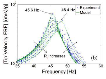
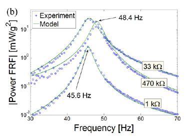
36 Experimental Validation of Model Erturk and Inman, 2009
37 Review Covered the following concepts o Introduction to spring-mass-damper system modeling o Mass, stiffness, damping and external force o Mechanical resonance and damping ratio o Inductive Lumped mass parameter modeling of relative motion between magnet and coil under base excitation (Poulin et al., 2004) Correction factor (Oliver and Priya, 2009) o Piezoelectric Distributer parameter modeling of strain distribution in piezoelectric bimorph (Erturk and Inman, 2009) Next we will discuss the experimental methods used to validate the models

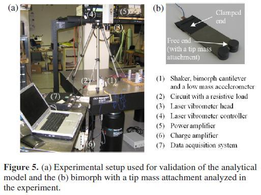
38 Typical Experimental Setup Marin et. al, 2011
39 Electrodynamic shakers which apply a force through a range of frequencies (harmonic or random inputs) Accelerometer - produce a signal proportional to acceleration at the point of attachment Laser vibrometers - produce a signal proportional to local velocity Measurement
 The analog signals can be sampled or digitized using a A/D converter Next, we use DFT to transform the digital time domain data to the frequency domain By computing Power Spectral")
40 Digital Acquisition Accelerometer and laser vibrometer output analog signals ex. x t and x (t) The analog signals can be sampled or digitized using a A/D converter Next, we use DFT to transform the digital time domain data to the frequency domain By computing Power Spectral Density and Cross Spectral Density we can create frequency response functions from which vibration data is extracted
41 Frequency response function 1 Autocorrelation : R xx ( ) lim T T T 0 x(t)x(t )d Power Spectral Density (PSD): S xx ( ) Crosscorrelation : R xf ( ) lim T T Cross Spectral Density: S xf ( ) 1 2 H jω DFT DFT T 0 x(t) f (t )d R xf ( )e j d = S xx(ω) S xf ω = 1 k mω 2 + cjω R xx ( )e j d Tells how fast x(t) is changing Tells how fast x(t) is changing relative to f(t) CPSD function in matlab Frequency response function H s = S xx(s) S xf s = 1 ms 2 + cs + k Transfer function γ 2 = S xf (ω) 2 S xx (ω)s ff (ω), 0 γ2 1 Coherence
42 Experimental Modal Analysis Oliver, J., Priya, S Design, Fabrication, and Modeling of a Four-bar Electromagnetic Vibration Power Generator, Journal of Intelligent Material Systems and Structures. Extract all system parameters through curve fitting of experimental results H s = S xx(s) S xf s = 1 ms 2 + cs + k = 1 s 2 + 2ζω n s + ω n 2 ζ = c 2 km ω n = k m
43 Other damping estimation methods Peak picking or 3 db method Logarithmic decrement method H( a ) H( b ) H( d ) 2 z b a 2 d
44 Power characterization Inductive Piezoelectric It has been proven, that the extraction of electrical power is maximized when ζ E = ζ M. Φ T i(t) R L,opt = R coil + Φ T 2 χ r s U t c m R L,opt = R s + 1 jωc
45 Vibration energy harvesting U = FR L Φ T Z e + R L Z jω + Φ T 2 U t = jωκ r M b L 2ζ r ω r jω + ω r 2 ω 2 L Φ r x dx M 0 t Φ r (L) C p a + a s + jωκ 2R r χ r L ω 2 Y 0 e jωt Φ T B(y c, z c ) L coil cos θ y c, z c Φ(y b ) Geometry and source parameters + Material parameters Harvester performance κ r = d 31h pc b s 11 E dφ r (x) dx x=l
46 Maximum power extraction for given geometry and source Maximum power conversion occurs at resonance Inductive high relative velocity Piezoelectric high relative strain (b) x(t) Tip mass C K y(t) Harvester Base Vibration Input mz + c z + k z = my
47 Maximum Power Extraction z t = k m ω2 ω c Tω m 2 Y sin ωt φ Maximum power conversion occurs at resonance at peak amplitude z t = 1 2ζ T 2 Y sin ω nt φ The maximum power dissipated into an electrical load consists of multiplying maximum applied force applied to the damper caused by the load itself times maximum relative velocity. Where P max = z max = c E z max z max ω n 2ζ T 2 Y
48 Maximum Power Extraction Therefore P max = c E ω n Y 2ζ T 2 ω n Y 2ζ T 2 P max = c E ω n 2 Y 2 2ζ T 2 Substituting ζ E = c E 2mω n P max = 2ζ E mω n ω n 2 Y 2 4ζ T 2 The extraction of electrical power is maximized when ζ E = ζ M therefore ζ e = ζ T 2. P max = mω n 3 Y 2 4ζ T P max = ma2 4ζ T ω n
49 Vibration energy harvesting U = FR L Φ T Z e + R L Z jω + Φ T 2 U t = jωκ r M b L 2ζ r ω r jω + ω r 2 ω 2 L Φ r x dx M 0 t Φ r (L) C p a + a s + jωκ 2R r χ r L ω 2 Y 0 e jωt Φ T B(y c, z c ) L coil cos θ y c, z c Φ(y b ) Geometry and source parameters + Material parameters Harvester performance κ r = d 31h pc b s 11 E dφ r (x) dx x=l
50 Inductive coupling (magnets) Φ T B(y c, z c ) L coil cos θ y c, z c Φ(y b ) Neodymium Iron Boron Magnetic Field Strength koe Curie temperature F (310 C) Operating temperature F (80 C) Samarium Cobalt Magnetic Field Strength koe Curie temperature F (750 C) Operating temperature F (300 C)
 fill factor = A wire L wire π")

51 Inductive coupling (coil) Φ T B(y c, z c ) L coil cos θ y c, z c Φ(y b ) fill factor = A wire L wire π r o 2 r i 2 t The fill factor of scramble wound coils will vary but a figure of 50 to 60% could be assumed.
 35 8 6 P avg, Simulated 30 25 20 V avg, Simulated Φ T B(y c, z c ) L coil cos θ y c, z c Φ(y b ) 4 2 15 10 5 10 8 6 4 2 38 AWG (100 μm dia) P avg, Simulated 8 7 6 5 4 3 2 1 0 0")
52 P avg (mw) V avg (V) P avg (mw) V avg (V) Inductive coupling (coil) cont AWG (40 μm dia) P avg, Simulated V avg, Simulated Φ T B(y c, z c ) L coil cos θ y c, z c Φ(y b ) AWG (100 μm dia) P avg, Simulated Resistance (kohm) V avg, Simulated Resistance (kohm) Assuming fill factor remains constant decreasing wire size does not affect the power output Resistance (kohm) Resistance (kohm)
53 Piezoelectric coupling κ r = d 31h pc b s 11 E dφ r (x) dx x=l d 31 is the piezoelectric constant s 11 E is the elastic constant d 31 while s 11 E FOM on resonance k Q / s 2 E 31 m 11
54 Piezoelectric coupling (doping) Typical doping effect on piezoelectric properties Kind Dopants Effect Hardener Acceptor Ion Li 1+, K 1+, Fe 3+, Ni 2+, Co 2+, Mn 2+ FOM on resonance k Q / s Decrease in piezoelectric constant, d Decrease in elastic compliance, s Decrease in electromechanical coupling factor, k Increase in Q κ r = d 31h pc b s 11 E 2 E 31 m 11 dφ r (x) dx x=l Softener Donor Ion La 3+, Bi 3+, Nb 5+, W 6+, Ta 5+ Increase in piezoelectric constant, d Increase in elastic compliance, s Increase in electromechanical coupling factor, k Decrease in Q

55 Textured Ceramics
56 Vibration energy harvesting Geometry and source parameters Φ T B(y c, z c ) L coil cos θ y c, z c Φ(y b ) κ r = d 31h pc b s 11 E + Material parameters Harvester performance Which Mechanism? dφ r (x) dx x=l Size?
57 Inductive or Piezoelectric? (a) Inductive: U = N B t suggesting P V 2 Piezoelectric: A = N B t L2 = B t L3 U = σ j g ij t = ρag ij L 2 ma A g ij L = ρl3 a L 2 g ij L = suggesting P α V 4/3 Marin et. Al, 2011
58 Survey of state of art P max = ma2 4ζ T ω n Normalize by source terms to compare coupling as a function of size Marin et. Al, 2011
59 Harvester size? High frequency 17 mw 50 Hz 0.2 G ~ 70 cm 3 Low frequency 4 mw Hz 0.25 G ~ 6 cm 3 Marin et. Al, 2011
Dynamics of structures
 Dynamics of structures 1.2 Viscous damping Luc St-Pierre October 30, 2017 1 / 22 Summary so far We analysed the spring-mass system and found that its motion is governed by: mẍ(t) + kx(t) = 0 k y m x x
Chapter 5 Design. D. J. Inman 1/51 Mechanical Engineering at Virginia Tech
 Chapter 5 Design Acceptable vibration levels (ISO) Vibration isolation Vibration absorbers Effects of damping in absorbers Optimization Viscoelastic damping treatments Critical Speeds Design for vibration
Chapter 7 Vibration Measurement and Applications
 Chapter 7 Vibration Measurement and Applications Dr. Tan Wei Hong School of Mechatronic Engineering Universiti Malaysia Perlis (UniMAP) Pauh Putra Campus ENT 346 Vibration Mechanics Chapter Outline 7.1
Modeling and Experimentation: Mass-Spring-Damper System Dynamics
 Modeling and Experimentation: Mass-Spring-Damper System Dynamics Prof. R.G. Longoria Department of Mechanical Engineering The University of Texas at Austin July 20, 2014 Overview 1 This lab is meant to
Introduction to Vibration. Mike Brennan UNESP, Ilha Solteira São Paulo Brazil
 Introduction to Vibration Mike Brennan UNESP, Ilha Solteira São Paulo Brazil Vibration Most vibrations are undesirable, but there are many instances where vibrations are useful Ultrasonic (very high
Finite Element Analysis of Piezoelectric Cantilever
 Finite Element Analysis of Piezoelectric Cantilever Nitin N More Department of Mechanical Engineering K.L.E S College of Engineering and Technology, Belgaum, Karnataka, India. Abstract- Energy (or power)
Introduction to Vibration. Professor Mike Brennan
 Introduction to Vibration Professor Mie Brennan Introduction to Vibration Nature of vibration of mechanical systems Free and forced vibrations Frequency response functions Fundamentals For free vibration
Appendix C. Modal Analysis of a Uniform Cantilever with a Tip Mass. C.1 Transverse Vibrations. Boundary-Value Problem
 Appendix C Modal Analysis of a Uniform Cantilever with a Tip Mass C.1 Transverse Vibrations The following analytical modal analysis is given for the linear transverse vibrations of an undamped Euler Bernoulli
Math Assignment 5
 Math 2280 - Assignment 5 Dylan Zwick Fall 2013 Section 3.4-1, 5, 18, 21 Section 3.5-1, 11, 23, 28, 35, 47, 56 Section 3.6-1, 2, 9, 17, 24 1 Section 3.4 - Mechanical Vibrations 3.4.1 - Determine the period
Chapter 3 Mathematical Methods
 Chapter 3 Mathematical Methods Slides to accompany lectures in Vibro-Acoustic Design in Mechanical Systems 0 by D. W. Herrin Department of Mechanical Engineering Lexington, KY 40506-0503 Tel: 859-8-0609
SENSOR DESIGN FOR PIEZOELECTRIC CANTILEVER BEAM ENERGY HARVESTERS
 SENSOR DESIGN FOR PIEZOELECTRIC CANTILEVER BEAM ENERGY HARVESTERS Michael I. Friswell and Sondipon Adhikari School of Engineering Swansea University Singleton Park, Swansea SA2 8PP, UK E-mail: m.i.friswell@swansea.ac.uk;
The Phasor Analysis Method For Harmonically Forced Linear Systems
 The Phasor Analysis Method For Harmonically Forced Linear Systems Daniel S. Stutts, Ph.D. April 4, 1999 Revised: 10-15-010, 9-1-011 1 Introduction One of the most common tasks in vibration analysis is
Nonlinear Considerations in Energy Harvesting
 Nonlinear Considerations in Energy Harvesting Daniel J. Inman Alper Erturk* Amin Karami Center for Intelligent Material Systems and Structures Virginia Tech Blacksburg, VA 24061, USA dinman@vt.edu www.cimss.vt.edu
Frequency Response of Linear Time Invariant Systems
 ME 328, Spring 203, Prof. Rajamani, University of Minnesota Frequency Response of Linear Time Invariant Systems Complex Numbers: Recall that every complex number has a magnitude and a phase. Example: z
EE C245 - ME C218. Fall 2003
 EE C45 - E C8 Introduction to ES Design Fall Roger Howe and Thara Srinivasan ecture 9 Energy ethods II Today s ecture echanical structures under driven harmonic motion develop analytical techniques for
Finite Element Analysis and Experiment on a Piezoelectric Harvester with Multiple Cantilevers
 doi: 10.14355/ijep.2015.04.003 Finite Element Analysis and Experiment on a Piezoelectric Harvester with Multiple Cantilevers Hongbing WANG *1, Chunhua SUN 2, Zhirong LI 3, Yiping ZhANG 4 Department of
Laboratory notes. Torsional Vibration Absorber
 Titurus, Marsico & Wagg Torsional Vibration Absorber UoB/1-11, v1. Laboratory notes Torsional Vibration Absorber Contents 1 Objectives... Apparatus... 3 Theory... 3 3.1 Background information... 3 3. Undamped
Raktim Bhattacharya. . AERO 632: Design of Advance Flight Control System. Preliminaries
 . AERO 632: of Advance Flight Control System. Preliminaries Raktim Bhattacharya Laboratory For Uncertainty Quantification Aerospace Engineering, Texas A&M University. Preliminaries Signals & Systems Laplace
Laboratory handouts, ME 340
 Laboratory handouts, ME 34 This document contains summary theory, solved exercises, prelab assignments, lab instructions, and report assignments for Lab 6. 214-216 Harry Dankowicz, unless otherwise noted
Chapter 14 Periodic Motion
 Chapter 14 Periodic Motion 1 Describing Oscillation First, we want to describe the kinematical and dynamical quantities associated with Simple Harmonic Motion (SHM), for example, x, v x, a x, and F x.
ME 375 EXAM #1 Friday, March 13, 2015 SOLUTION
 ME 375 EXAM #1 Friday, March 13, 2015 SOLUTION PROBLEM 1 A system is made up of a homogeneous disk (of mass m and outer radius R), particle A (of mass m) and particle B (of mass m). The disk is pinned
Identification Methods for Structural Systems. Prof. Dr. Eleni Chatzi Lecture March, 2016
 Prof. Dr. Eleni Chatzi Lecture 4-09. March, 2016 Fundamentals Overview Multiple DOF Systems State-space Formulation Eigenvalue Analysis The Mode Superposition Method The effect of Damping on Structural
Outline of parts 1 and 2
 to Harmonic Loading http://intranet.dica.polimi.it/people/boffi-giacomo Dipartimento di Ingegneria Civile Ambientale e Territoriale Politecnico di Milano March, 6 Outline of parts and of an Oscillator
Research Article Development and Validation of an Enhanced Coupled-Field Model for PZT Cantilever Bimorph Energy Harvester
 Mathematical Problems in Engineering Volume 213, Article ID 98161, 1 pages http://dx.doi.org/1.11/213/98161 Research Article Development and Validation of an Enhanced Coupled-Field Model for PZT Cantilever
Maximizing Output Power in a Cantilevered Piezoelectric Vibration Energy Harvester by Electrode Design
 Maximizing Output Power in a Cantilevered Piezoelectric Vibration Energy Harvester by Electrode Design Item Type Article Authors Du, Sijun; Jia, Yu; Seshia, Ashwin A. Citation Du, S., Jia, Y., & Seshia,
Robotics Intelligent sensors (part 2)
") Robotics Intelligent sensors (part ) Tullio Facchinetti Tuesday 6 th December, 06 http://robot.unipv.it/toolleeo Pressure measurement static pressure is a force applied to
Robotics Intelligent sensors (part ) Tullio Facchinetti Tuesday 6 th December, 06 http://robot.unipv.it/toolleeo Pressure measurement static pressure is a force applied to
Differential Equations
 Differential Equations A differential equation (DE) is an equation which involves an unknown function f (x) as well as some of its derivatives. To solve a differential equation means to find the unknown
EE C245 - ME C218 Introduction to MEMS Design Fall Today s Lecture
 EE C45 - ME C8 Introduction to MEMS Design Fall 3 Roger Howe and Thara Srinivasan Lecture 9 Energy Methods II Today s Lecture Mechanical structures under driven harmonic motion develop analytical techniques
CIVL 8/7117 Chapter 12 - Structural Dynamics 1/75. To discuss the dynamics of a single-degree-of freedom springmass
 CIV 8/77 Chapter - /75 Introduction To discuss the dynamics of a single-degree-of freedom springmass system. To derive the finite element equations for the time-dependent stress analysis of the one-dimensional
Module 4: Dynamic Vibration Absorbers and Vibration Isolator Lecture 19: Active DVA. The Lecture Contains: Development of an Active DVA
 The Lecture Contains: Development of an Active DVA Proof Mass Actutor Application of Active DVA file:///d /chitra/vibration_upload/lecture19/19_1.htm[6/25/2012 12:35:51 PM] In this section, we will consider
Laboratory handouts, ME 340
 Laboratory handouts, ME 340 This document contains summary theory, solved exercises, prelab assignments, lab instructions, and report assignments for Lab 4. 2014-2016 Harry Dankowicz, unless otherwise
Modeling of Resonators
 . 23 Modeling of Resonators 23 1 Chapter 23: MODELING OF RESONATORS 23 2 23.1 A GENERIC RESONATOR A second example where simplified discrete modeling has been found valuable is in the assessment of the
Vibrations of Single Degree of Freedom Systems
 Vibrations of Single Degree of Freedom Systems CEE 541. Structural Dynamics Department of Civil and Environmental Engineering Duke University Henri P. Gavin Fall, 16 This document describes free and forced
Measurement Techniques for Engineers. Motion and Vibration Measurement
 Measurement Techniques for Engineers Motion and Vibration Measurement Introduction Quantities that may need to be measured are velocity, acceleration and vibration amplitude Quantities useful in predicting
Dr.Vinod Hosur, Professor, Civil Engg.Dept., Gogte Institute of Technology, Belgaum
 STRUCTURAL DYNAMICS Dr.Vinod Hosur, Professor, Civil Engg.Dept., Gogte Institute of Technology, Belgaum Overview of Structural Dynamics Structure Members, joints, strength, stiffness, ductility Structure
Effect of Strain Nodes and Electrode Configuration on Piezoelectric Energy Harvesting From Cantilevered Beams
 A. Erturk 1 Center for Intelligent Material Systems and Structures, Department of Engineering Science and Mechanics, Virginia Tech, Blacksburg, VA 24061 e-mail: erturk@vt.edu P. A. Tarazaga J. R. Farmer
Dynamics of Structures: Theory and Analysis
 1. Free vibrations 2. Forced vibrations 3. Transient response 4. Damping mechanisms Dynamics of Structures: Theory and Analysis Steen Krenk Technical University of Denmark 5. Modal analysis I: Basic idea
Vibration Testing. an excitation source a device to measure the response a digital signal processor to analyze the system response
 Vibration Testing For vibration testing, you need an excitation source a device to measure the response a digital signal processor to analyze the system response i) Excitation sources Typically either
(Refer Slide Time: 1: 19)
") Mechanical Measurements and Metrology Prof. S. P. Venkateshan Department of Mechanical Engineering Indian Institute of Technology, Madras Module - 4 Lecture - 46 Force Measurement So this will be lecture
Mechanical Measurements and Metrology Prof. S. P. Venkateshan Department of Mechanical Engineering Indian Institute of Technology, Madras Module - 4 Lecture - 46 Force Measurement So this will be lecture
R-L-C Circuits and Resonant Circuits
 P517/617 Lec4, P1 R-L-C Circuits and Resonant Circuits Consider the following RLC series circuit What's R? Simplest way to solve for is to use voltage divider equation in complex notation. X L X C in 0
Oscillatory Motion SHM
 Chapter 15 Oscillatory Motion SHM Dr. Armen Kocharian Periodic Motion Periodic motion is motion of an object that regularly repeats The object returns to a given position after a fixed time interval A
C.-H. Lamarque. University of Lyon/ENTPE/LGCB & LTDS UMR CNRS 5513
 Nonlinear Dynamics of Smooth and Non-Smooth Systems with Application to Passive Controls 3rd Sperlonga Summer School on Mechanics and Engineering Sciences on Dynamics, Stability and Control of Flexible
In the presence of viscous damping, a more generalized form of the Lagrange s equation of motion can be written as
 2 MODELING Once the control target is identified, which includes the state variable to be controlled (ex. speed, position, temperature, flow rate, etc), and once the system drives are identified (ex. force,
ECEN 420 LINEAR CONTROL SYSTEMS. Lecture 6 Mathematical Representation of Physical Systems II 1/67
 1/67 ECEN 420 LINEAR CONTROL SYSTEMS Lecture 6 Mathematical Representation of Physical Systems II State Variable Models for Dynamic Systems u 1 u 2 u ṙ. Internal Variables x 1, x 2 x n y 1 y 2. y m Figure
First and Second Order Circuits. Claudio Talarico, Gonzaga University Spring 2015
 First and Second Order Circuits Claudio Talarico, Gonzaga University Spring 2015 Capacitors and Inductors intuition: bucket of charge q = Cv i = C dv dt Resist change of voltage DC open circuit Store voltage
10 Measurement of Acceleration, Vibration and Shock Transducers
 Chapter 10: Acceleration, Vibration and Shock Measurement Dr. Lufti Al-Sharif (Revision 1.0, 25/5/2008) 1. Introduction This chapter examines the measurement of acceleration, vibration and shock. It starts
Laboratory handout 5 Mode shapes and resonance
 laboratory handouts, me 34 82 Laboratory handout 5 Mode shapes and resonance In this handout, material and assignments marked as optional can be skipped when preparing for the lab, but may provide a useful
Lecture 19. Measurement of Solid-Mechanical Quantities (Chapter 8) Measuring Strain Measuring Displacement Measuring Linear Velocity
 Measuring Strain Measuring Displacement Measuring Linear Velocity") MECH 373 Instrumentation and Measurements Lecture 19 Measurement of Solid-Mechanical Quantities (Chapter 8) Measuring Strain Measuring Displacement Measuring Linear Velocity Measuring Accepleration and
MECH 373 Instrumentation and Measurements Lecture 19 Measurement of Solid-Mechanical Quantities (Chapter 8) Measuring Strain Measuring Displacement Measuring Linear Velocity Measuring Accepleration and
سایت آموزش مهندسی مکانیک
 http://www.drshokuhi.com سایت آموزش مهندسی مکانیک 1 Single-degree-of-freedom Systems 1.1 INTRODUCTION In this chapter the vibration of a single-degree-of-freedom system will be analyzed and reviewed. Analysis,
Mathematical Modeling and response analysis of mechanical systems are the subjects of this chapter.
 Chapter 3 Mechanical Systems A. Bazoune 3.1 INRODUCION Mathematical Modeling and response analysis of mechanical systems are the subjects of this chapter. 3. MECHANICAL ELEMENS Any mechanical system consists
Math 266 Midterm Exam 2
 Math 266 Midterm Exam 2 March 2st 26 Name: Ground Rules. Calculator is NOT allowed. 2. Show your work for every problem unless otherwise stated (partial credits are available). 3. You may use one 4-by-6
Transduction Based on Changes in the Energy Stored in an Electrical Field
 Lecture 6- Transduction Based on Changes in the Energy Stored in an Electrical Field Actuator Examples Microgrippers Normal force driving In-plane force driving» Comb-drive device F = εav d 1 ε oε F rwv
e jωt = cos(ωt) + jsin(ωt),
 + jsin(ωt),") This chapter introduces you to the most useful mechanical oscillator model, a mass-spring system with a single degree of freedom. Basic understanding of this system is the gateway to the understanding
This chapter introduces you to the most useful mechanical oscillator model, a mass-spring system with a single degree of freedom. Basic understanding of this system is the gateway to the understanding
Chapter 2 Basics of Vibration Dynamics
 Chapter 2 Basics of Vibration Dynamics Vibrations are mechanical oscillations about an equilibrium position. There are cases when vibrations are desirable, such as in certain types of machine tools or
Exercises Lecture 15
 AM1 Mathematical Analysis 1 Oct. 011 Feb. 01 Date: January 7 Exercises Lecture 15 Harmonic Oscillators In classical mechanics, a harmonic oscillator is a system that, when displaced from its equilibrium
1-DOF Forced Harmonic Vibration. MCE371: Vibrations. Prof. Richter. Department of Mechanical Engineering. Handout 8 Fall 2011
 MCE371: Vibrations Prof. Richter Department of Mechanical Engineering Handout 8 Fall 2011 Harmonic Forcing Functions Transient vs. Steady Vibration Follow Palm, Sect. 4.1, 4.9 and 4.10 Harmonic forcing
PH.D. PRELIMINARY EXAMINATION MATHEMATICS
 UNIVERSITY OF CALIFORNIA, BERKELEY Dept. of Civil and Environmental Engineering FALL SEMESTER 2014 Structural Engineering, Mechanics and Materials NAME PH.D. PRELIMINARY EXAMINATION MATHEMATICS Problem
Final Exam December 11, 2017
 Final Exam Instructions: You have 120 minutes to complete this exam. This is a closed-book, closed-notes exam. You are NOT allowed to use a calculator with communication capabilities during the exam. Usage
Lecture 4: R-L-C Circuits and Resonant Circuits
 Lecture 4: R-L-C Circuits and Resonant Circuits RLC series circuit: What's V R? Simplest way to solve for V is to use voltage divider equation in complex notation: V X L X C V R = in R R + X C + X L L
MAE106 Laboratory Exercises Lab # 6 - Vibrating systems
 MAE106 Laboratory Exercises Lab # 6 - Vibrating systems Goals Understand how the oscillations in a mechanical system affect its behavior. Parts & equipment Qty Part/Equipment 1 Seeeduino board 1 Motor
Q. 1 Q. 25 carry one mark each.
 GATE 5 SET- ELECTRONICS AND COMMUNICATION ENGINEERING - EC Q. Q. 5 carry one mark each. Q. The bilateral Laplace transform of a function is if a t b f() t = otherwise (A) a b s (B) s e ( a b) s (C) e as
School of Mechanical Engineering Purdue University
 Case Study ME375 Frequency Response - 1 Case Study SUPPORT POWER WIRE DROPPERS Electric train derives power through a pantograph, which contacts the power wire, which is suspended from a catenary. During
Driven RLC Circuits Challenge Problem Solutions
 Driven LC Circuits Challenge Problem Solutions Problem : Using the same circuit as in problem 6, only this time leaving the function generator on and driving below resonance, which in the following pairs
CE 6701 Structural Dynamics and Earthquake Engineering Dr. P. Venkateswara Rao
 CE 6701 Structural Dynamics and Earthquake Engineering Dr. P. Venkateswara Rao Associate Professor Dept. of Civil Engineering SVCE, Sriperumbudur Difference between static loading and dynamic loading Degree
Lecture 27: Structural Dynamics - Beams.
 Chapter #16: Structural Dynamics and Time Dependent Heat Transfer. Lectures #1-6 have discussed only steady systems. There has been no time dependence in any problems. We will investigate beam dynamics
MATH 251 Week 6 Not collected, however you are encouraged to approach all problems to prepare for exam
 MATH 51 Week 6 Not collected, however you are encouraged to approach all problems to prepare for exam A collection of previous exams could be found at the coordinator s web: http://www.math.psu.edu/tseng/class/m51samples.html
Chapter III Harmonic Excitation of Single-Degree-of-Freedom systems Forced Vibration
 Chapter III Harmonic Excitation of Single-Degree-of-Freedom systems Forced Vibration There are many sources of excitations that cause machines and structures to vibrate. They include Unbalance rotating
MATH 251 Final Examination August 14, 2015 FORM A. Name: Student Number: Section:
 MATH 251 Final Examination August 14, 2015 FORM A Name: Student Number: Section: This exam has 11 questions for a total of 150 points. Show all your work! In order to obtain full credit for partial credit
ScienceDirect. Effect of Heat on the Performance of Novel Energy Harvester by using PZT-5H Transducers
 Available online at www.sciencedirect.com ScienceDirect Procedia Engineering 144 (016 ) 668 673 1th International Conference on Vibration Problems, ICOVP 015 Effect of Heat on the Performance of Novel
RLC Circuit (3) We can then write the differential equation for charge on the capacitor. The solution of this differential equation is
 We can then write the differential equation for charge on the capacitor. The solution of this differential equation is") RLC Circuit (3) We can then write the differential equation for charge on the capacitor The solution of this differential equation is (damped harmonic oscillation!), where 25 RLC Circuit (4) If we charge
RLC Circuit (3) We can then write the differential equation for charge on the capacitor The solution of this differential equation is (damped harmonic oscillation!), where 25 RLC Circuit (4) If we charge
Introduction to Geotechnical Earthquake Engineering
 Module 1 Introduction to Geotechnical Earthquake Engineering by Dr. Deepankar Choudhury Professor Department of Civil Engineering IIT Bombay, Powai, Mumbai 400 076, India. Email: dc@civil.iitb.ac.in URL:
Theoretical Basis of Modal Analysis
 American Journal of Mechanical Engineering, 03, Vol., No. 7, 73-79 Available online at http://pubs.sciepub.com/ajme//7/4 Science and Education Publishing DOI:0.69/ajme--7-4 heoretical Basis of Modal Analysis
Introduction to Modern Control MT 2016
 CDT Autonomous and Intelligent Machines & Systems Introduction to Modern Control MT 2016 Alessandro Abate Lecture 2 First-order ordinary differential equations (ODE) Solution of a linear ODE Hints to nonlinear
STRUCTURAL DYNAMICS BASICS:
 BASICS: STRUCTURAL DYNAMICS Real-life structures are subjected to loads which vary with time Except self weight of the structure, all other loads vary with time In many cases, this variation of the load
Introduction to structural dynamics
 Introduction to structural dynamics p n m n u n p n-1 p 3... m n-1 m 3... u n-1 u 3 k 1 c 1 u 1 u 2 k 2 m p 1 1 c 2 m2 p 2 k n c n m n u n p n m 2 p 2 u 2 m 1 p 1 u 1 Static vs dynamic analysis Static
A Guide to linear dynamic analysis with Damping
 A Guide to linear dynamic analysis with Damping This guide starts from the applications of linear dynamic response and its role in FEA simulation. Fundamental concepts and principles will be introduced
Oscillations. Simple Harmonic Motion of a Mass on a Spring The equation of motion for a mass m is attached to a spring of constant k is
 Dr. Alain Brizard College Physics I (PY 10) Oscillations Textbook Reference: Chapter 14 sections 1-8. Simple Harmonic Motion of a Mass on a Spring The equation of motion for a mass m is attached to a spring
Faraday's Law ds B B G G ΦB B ds Φ ε = d B dt
 Faraday's Law ds ds ε= d Φ dt Φ Global Review Electrostatics» motion of q in external E-field» E-field generated by Σq i Magnetostatics» motion of q and i in external -field» -field generated by I Electrodynamics»
Experimental Modal Analysis of a Flat Plate Subjected To Vibration
 American Journal of Engineering Research (AJER) 2016 American Journal of Engineering Research (AJER) e-issn: 2320-0847 p-issn : 2320-0936 Volume-5, Issue-6, pp-30-37 www.ajer.org Research Paper Open Access
Vibrational Motion. Chapter 5. P. J. Grandinetti. Sep. 13, Chem P. J. Grandinetti (Chem. 4300) Vibrational Motion Sep.
 Vibrational Motion Sep.") Vibrational Motion Chapter 5 P. J. Grandinetti Chem. 4300 Sep. 13, 2017 P. J. Grandinetti (Chem. 4300) Vibrational Motion Sep. 13, 2017 1 / 20 Simple Harmonic Oscillator Simplest model for harmonic oscillator
Vibrational Motion Chapter 5 P. J. Grandinetti Chem. 4300 Sep. 13, 2017 P. J. Grandinetti (Chem. 4300) Vibrational Motion Sep. 13, 2017 1 / 20 Simple Harmonic Oscillator Simplest model for harmonic oscillator
2.4 Models of Oscillation
 2.4 Models of Oscillation In this section we give three examples of oscillating physical systems that can be modeled by the harmonic oscillator equation. Such models are ubiquitous in physics, but are
Handout 10: Inductance. Self-Inductance and inductors
 1 Handout 10: Inductance Self-Inductance and inductors In Fig. 1, electric current is present in an isolate circuit, setting up magnetic field that causes a magnetic flux through the circuit itself. This
ET3-7: Modelling II(V) Electrical, Mechanical and Thermal Systems
 Electrical, Mechanical and Thermal Systems") ET3-7: Modelling II(V) Electrical, Mechanical and Thermal Systems Agenda of the Day 1. Resume of lesson I 2. Basic system models. 3. Models of basic electrical system elements 4. Application of Matlab/Simulink
ET3-7: Modelling II(V) Electrical, Mechanical and Thermal Systems Agenda of the Day 1. Resume of lesson I 2. Basic system models. 3. Models of basic electrical system elements 4. Application of Matlab/Simulink
Faculty of Computers and Information. Basic Science Department
 18--018 FCI 1 Faculty of Computers and Information Basic Science Department 017-018 Prof. Nabila.M.Hassan 18--018 FCI Aims of Course: The graduates have to know the nature of vibration wave motions with
Module I Module I: traditional test instrumentation and acquisition systems. Prof. Ramat, Stefano
 Preparatory Course (task NA 3.6) Basics of experimental testing and theoretical background Module I Module I: traditional test instrumentation and acquisition systems Prof. Ramat, Stefano Transducers A
EE 5344 Introduction to MEMS CHAPTER 6 Mechanical Sensors. 1. Position Displacement x, θ 2. Velocity, speed Kinematic
 I. Mechanical Measurands: 1. Classification of main types: EE 5344 Introduction MEMS CHAPTER 6 Mechanical Sensors 1. Position Displacement x, θ. Velocity, speed Kinematic dx dθ v =, = ω 3. Acceleration
Modeling and Simulation Revision IV D R. T A R E K A. T U T U N J I P H I L A D E L P H I A U N I V E R S I T Y, J O R D A N
 Modeling and Simulation Revision IV D R. T A R E K A. T U T U N J I P H I L A D E L P H I A U N I V E R S I T Y, J O R D A N 2 0 1 7 Modeling Modeling is the process of representing the behavior of a real
ELECTROMAGNETIC INDUCTION
 ELECTROMAGNETIC INDUCTION 1. Magnetic Flux 2. Faraday s Experiments 3. Faraday s Laws of Electromagnetic Induction 4. Lenz s Law and Law of Conservation of Energy 5. Expression for Induced emf based on
PREMED COURSE, 14/08/2015 OSCILLATIONS
 PREMED COURSE, 14/08/2015 OSCILLATIONS PERIODIC MOTIONS Mechanical Metronom Laser Optical Bunjee jumping Electrical Astronomical Pulsar Biological ECG AC 50 Hz Another biological exampe PERIODIC MOTIONS
Nonlinear Dynamic Systems Homework 1
 Nonlinear Dynamic Systems Homework 1 1. A particle of mass m is constrained to travel along the path shown in Figure 1, which is described by the following function yx = 5x + 1x 4, 1 where x is defined
Vibrations Qualifying Exam Study Material
 Vibrations Qualifying Exam Study Material The candidate is expected to have a thorough understanding of engineering vibrations topics. These topics are listed below for clarification. Not all instructors
Chapter 31 Electromagnetic Oscillations and Alternating Current LC Oscillations, Qualitatively
 Chapter 3 Electromagnetic Oscillations and Alternating Current LC Oscillations, Qualitatively In the LC circuit the charge, current, and potential difference vary sinusoidally (with period T and angular
Department of Architecture & Civil Engineering ( ) 2 2a. L = 65 2 ρπa4 L. + asinα = 3aθ 2. ( ) = a 1 cos( θ ρπa4 L.
 2 2a. L = 65 2 ρπa4 L. + asinα = 3aθ 2. ( ) = a 1 cos( θ ρπa4 L.") MODE ANSWER age: 1 QUESTION Mass of tube = ρπ 3a ( ) ( a) Moment of inertia of tube = ρπ 3 Mass of bar = ρπa Moment of inertia of bar = = 5ρπa ( 3a) 4 a ( ) 4 ρπ ( a )4 = 1 3 ρπa4 Horizontal displacement
MODE ANSWER age: 1 QUESTION Mass of tube = ρπ 3a ( ) ( a) Moment of inertia of tube = ρπ 3 Mass of bar = ρπa Moment of inertia of bar = = 5ρπa ( 3a) 4 a ( ) 4 ρπ ( a )4 = 1 3 ρπa4 Horizontal displacement
Preliminary Examination - Dynamics
 Name: University of California, Berkeley Fall Semester, 2018 Problem 1 (30% weight) Preliminary Examination - Dynamics An undamped SDOF system with mass m and stiffness k is initially at rest and is then
INF5490 RF MEMS. LN03: Modeling, design and analysis. Spring 2008, Oddvar Søråsen Department of Informatics, UoO
 INF5490 RF MEMS LN03: Modeling, design and analysis Spring 2008, Oddvar Søråsen Department of Informatics, UoO 1 Today s lecture MEMS functional operation Transducer principles Sensor principles Methods
Dynamics of the synchronous machine
 ELEC0047 - Power system dynamics, control and stability Dynamics of the synchronous machine Thierry Van Cutsem t.vancutsem@ulg.ac.be www.montefiore.ulg.ac.be/~vct October 2018 1 / 38 Time constants and
An energy harvester with Two degrees of freedom Nonlinear oscillations. Zuyao Wang
 International Conference on Advances in Energy and Environmental Science (ICAEES 05) An energy harvester with Two degrees of freedom Nonlinear oscillations Zuyao Wang School of Sciences, Zhejiang University
Get Discount Coupons for your Coaching institute and FREE Study Material at ELECTROMAGNETIC INDUCTION
 ELECTROMAGNETIC INDUCTION 1. Magnetic Flux 2. Faraday s Experiments 3. Faraday s Laws of Electromagnetic Induction 4. Lenz s Law and Law of Conservation of Energy 5. Expression for Induced emf based on
2.4 Harmonic Oscillator Models
 2.4 Harmonic Oscillator Models In this section we give three important examples from physics of harmonic oscillator models. Such models are ubiquitous in physics, but are also used in chemistry, biology,
Chapter 5: Electromagnetic Induction
 Chapter 5: Electromagnetic Induction 5.1 Magnetic Flux 5.1.1 Define and use magnetic flux Magnetic flux is defined as the scalar product between the magnetic flux density, B with the vector of the area,