Short Course: Advanced Flow Diagnostic Techniques for Thermal Fluid Studies
|
|
|
- Daniella Lane
- 5 years ago
- Views:
Transcription
1 Short Course: Advanced Flow Diagnostic Techniques for Thermal Fluid Studies Lecture : Shadowgraph, Schlieren; Interferometry; Hotwire Anemometry, LDV and PDV Dr. Hui H Hu Department of Aerospace Engineering Iowa State University Ames, Iowa 50011, U.S.A
2 Shadowgraph, Schlieren and Interferometry
3 Refractive index: Light propagate through media λ n c / v 0 > 1 λ Index of refraction of a material generally increasing slightly with decreasing wavelength of the light. Such phenomena is called dispersion. 1+ K Lρ n 1 K ρ Gas Air He CO H n nm Liquid Water Ethyl alcohol Turpentine Benzene n L c Solid 0 Fused quartz Pyrex glass Crown glass Flint glass Plexiglas Lexan Polystyrene sapphire zircon Diamond 3x10 8 n m / s ~
4 Light Refraction Snell s Law: θ 1 n 1sin θ1 n sin θ n 1 < n Medium 1 Medium θ
5 Example, Refraction in Water Water Surface Pole


 Interferometry systems: response directly the difference of optical path length,, especially giving the index of reflection")
6 Index of refraction: λ n c / v 0 > 1 λ Depend on variation of index of refraction in a transparent medium and the resulting effect on a light beam passing through the test section Introduction-1 Shadowgraph systems: are used to indicate the variation of the second derivatives (normal to the light beam) of the index of refraction. Schlieren Systems: are used to indicate the variation of the first directive of the index of refraction shadowgraph depicting the flow generated by a bullet at supersonic speeds. (by Andrew Davidhazy ) Interferometry systems: response directly the difference of optical path length,, especially giving the index of reflection field within the flow field. Holographic interferometry image of shock-vortex interaction Schlieren images of the muzzle blast and supersonic bullet from firing a caliber high-powered rifle (by Gary S. Settles )


7 Introduction- Shadowgraph and Schlieren Systems are often used in shock waves and flame phenomena, in which density gradient is quite big. Interfereometry are often used to study a flow in which density gradient are small. While these techniques are mostly used for qualitative flow visualization, they can be used to determine pressure, density or temperature measurements theoretically. These techniques are often used to determine the integrated quantity over the length of light beam. These techniques are usually used for -D D flow without index of refraction or density variations along the beam. shadowgraph image of plumes during solidification process (by Lum Chee) temperature fields and the heat transfer around a heated cylinder Schlieren image
8 Introduction-3 Index of refraction is a function of thermodynamic state (density) for homogeneous medium: Lorenz-Lorentz Lorentz relationship: When n 1, n for gaseous flow: at standard condition, with n o and ρ o, : 1 n ρ n 1 + const When first and second derivative is determined as in Schlieren and shadowgraph apparatus: n 1 n 1 const ρ ρ const n0 1 const ρ 0 ρ n 1 ( n0 1) ρ0 n 1 ρ ρ0 n 1 ρ 1 n ρ ρ0 n y const y y n0 1 y ρ 1 n ρ ρ0 n y const y y n 1 y 0 0
9 Introduction-4 Application of the Schlieren and shadowgraph techniques: Compressible flow with shock waves Natural convective flow density changes density changes Flame and combustion system: density changes Temperature changes inside flows: For low speed flow with heat transfer: P constant ρ P T ρ T ρ P / RT y RT y T y n n0 1 ρ n0 1 ρ T y ρ0 y T ρ0 y T T ρ0 n y n 1 ρ y n y 0 n0 1 ρ T [ ρ T y 0 ρ T + ( ) T y ]
10 Copyright by Dr. Hui Iowa State University. All Rights Reserved! Introduction-5 For reversible, adiabatic process: For reversible, adiabatic process: y n k n P y n y n n P y n n n P y P n n P P const n k P P const P k k k k k 1) ( ) ( 1) ( ) 1 1 ( 1 C C specific heat; k the ratio of is ) ( v p 0 0 ρ ρ ρ ρ
11 Fundamentals of Schlieren System According to definition of index of refraction, the light velocity will be VC o /n. The slope of the wave front of the light: If the angle Δα' is quite small. dy dz C0 ΔZ Δτ n 1 Δ Z ΔZ ΔZ y+δy C0( Δ( ) / Δy) Δτ Δy n Δ Z 1 Δα' n ( Δ( ) / Δy) ΔZ Δy n 1 d( ) dy n 1 dn 1 dn d(ln n) dα' n[ ] dz n [ ] dz ( ) dz dz dz dy n dy n dy dy d y d(ln n) dz dy Parallel lights y λ n c / v 0 > 1 λ Δy Δα' Δ ΔZ Z Z Δα' 1 d( ) n 1 dn 1 dn d(ln n) dα' n[ ] dz n [ ] dz ( ) dz dz dy n dy n dy dy 1 dn n 1 dn α' ( ) dz α' dz n dy dy
12 Fundamentals of Schlieren System The intensity after the shape razor blade (knife edge) before the experiment I k a a K 0 I 0 The intensity after the deformation due to the variation of the index of refraction Δa Δa I d I k + I k (1 + ) I k ak ak ΔI I d I k Δa contrast I k I k ak d( contrast) f sensitivity : dα a Sensitivity is proportional to f and inversely to a k. K α f ± a K
13 Fundamentals of Schlieren System The intensity after the shape razor blade (knife edge) before the experiment I k a a K 0 I 0 The intensity after the deformation due to the variation of the index of refraction Δa Δa I d I k + I k (1 + ) I k ak ak ΔI I d I k Δa contrast I k I k ak d( contrast) f sensitivity : dα a Sensitivity is proportional to f and inversely to a k. K α f ± a K
14 Fundamentals of Schlieren System


15 Fundamentals of Schlieren System

16 Fundamentals of Schlieren System
17 Fundamentals of Schlieren System For a gas flow with density change: ΔI α f ± I k ak dn ΔI α' dz dy I k ρ ρ 0 n y n0 1 y ΔI f n 1 ± I a k K f dn ± dz a K dy ΔI f n0 1 ± I k ak ρ0 n0 1 dρ L ρ dy 0 dρ dz dy
18 Fundamentals of Schlieren System For a gas flow with constant pressure distribution: ΔI f dn ± dz I a k K dy T T ρ0 n y n0 1 ρ y ΔI f n0 1 ρ dt ± dz I k ak ρ 0 T dy ΔI f n0 1 P dt ± I k ak ρ 0 RT dy ΔI f n0 1 P dt ± L I a ρ RT dy k K 0 dz

19 Fundamentals of Schlieren System For a liquid flow: n is a function of temperature T. dn n T dy T y ΔI f dn f n T ± dz I a dy a k K K T y n T if n 1 const T y ΔI f n T ± L I a T y k K dz


20 Visualization of shock wave in a transonic/supersonic nozzle using Schlieren technique

 1-4.00 0.800-1.50 0.59 3-0.30 0.480 4-0.18 0.")

21 Lab#3: Pressure Measurements in a de Laval Nozzle Tank with compressed air Test section Tap No. Distance downstream of throat (inches) Area (Sq. inches)


22 1st, nd and 3 rd critic conditions nd critical shock is at nozzle exit Flow close to 3 rd critical Over-expanded expanded flow with shock between nozzle exit and throat Under- expanded flow Over- expanded flow 1 st critical shock is almost at the nozzle throat.

23 Alternative Schlieren system A. Setup with one converging and one plane mirror A. Setup with one converging mirror
24 Holographic Schlieren system
25 Shadowgraph technique Δy I sc I0 Δysc Δysc Δy + Z sc dα ΔI I sc I0 Δy 1 I0 I0 Δysc dα dα Z sc Z sc Δysc dy ΔI dα Z sc I0 dy 1 dn since α dz na dy ΔI Z sc d n dz I n dy 0 a Sensitive is proposal to Z sc
26 Shadowgraph technique Experimental setup with one converging mirror Experimental setup without lens or mirror
27 Schlieren vs. Shadowgraph Shadowgraph Displays a mere shadow Shows light ray displacement Contrast level responds to n y No knife edge used Schlieren Displays a focused image Shows ray refraction angle, ε Contrast level responds to n y Knife edge used for cutoff


28 Examples


29 Interferometers Unlike the Schlieren and shadowgraph systems, an interferometer does not depend upon the deflection of a light beam to determine density or index of refraction variation. Interferometers are often used for quantitative measurements

30 Interferometers

31 Coherent light Source Coherent sources... Two sources of light are said to be coherent if the waves emitted from them have the same frequency and are 'phase-linked'; that is, they have a zero or constant phase difference.
 λ λ if A0 A01 A0 then : AT A1 + A π π π π A0 [sin( ct Z0) + sin( ct Z0 Δ)] λ λ λ λ Δ π π Δ A0 cos sin( ct Z0 ) λ λ Therefore, the intensity of the combined wave (which is")
32 Interference of two coherence light waves Amplitude of a plate light wave in a homogeneous medium can be expressed as : π A A0 sin ( ct z) λ therefore : π π wave1: A1 A01 sin( ct Z0) λ λ π π wave : A A01 sin( ct Z0 Δ) λ λ if A0 A01 A0 then : AT A1 + A π π π π A0 [sin( ct Z0) + sin( ct Z0 Δ)] λ λ λ λ Δ π π Δ A0 cos sin( ct Z0 ) λ λ Therefore, the intensity of the combined wave (which is proportional to the square of the peak amplitude)will be : Δ I ~ 4A0 cos

33 Interference of light waves Thomas Young (1801)
34 Interferometers The ppticle path length along a light beam is defined as : PL ndz or C0 1 dz PL dz C λ 0 λ Therefore, the difference between path 1and path : ΔPL PL PL ndz ndz 0 1 path 1 path 1 dz dz ( 1 1 ) λ path 0 λ path λ The phase difference between the two wave will be : dz dz Δ π ( path 1 path 1 ) λ λ or Δ ΔPL π λ
 L λ0 or λ0ε λ0ε ρ0 ρ ρref const L n 1 L o for temepature measurements in gaseous flows λ0ε 1 T Tref L dn /")
35 Interferometers 1 ε ( n nref ) dz λ 0 n 1 Acording Glasdstone - Dale equation : ρ Const const ε ( ρ ρref ) dz λ 0 if only varies over a length L, then, the fringe shift will be : n nref ε L λ0 for gaseous flows const ε ( ρ ρref ) L λ0 or λ0ε λ0ε ρ0 ρ ρref const L n 1 L o for temepature measurements in gaseous flows λ0ε 1 T Tref L dn / DT

36 Examples


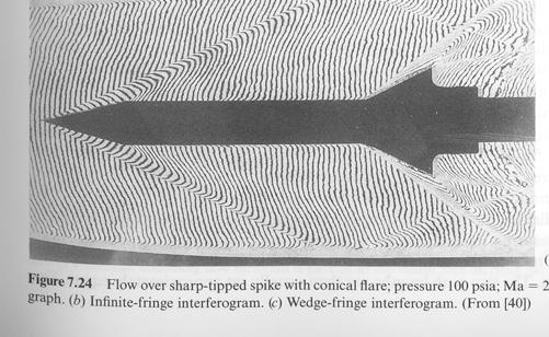

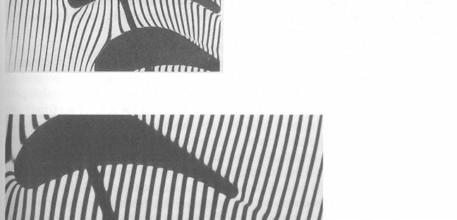

37 Examples
38 Methods for Local Flow Velocity Measurements


39 Methods to Measure Local Flow Velocity - 1 Mechanical methods: Taking advantage of force and moments that a moving stream applies on immersed objects. Vane anemometers Propeller anemometers
40 Methods to Measure Local Flow Velocity - Pressure difference methods: Utilize analytical relationship between the local velocity and the static and total pressures The tubes sensing static and stagnation pressures are usually combined into one instrument known as Pitotstatic tube. Pressure taps sensing static pressure (also the reference pressure for this measurement) are placed radially on the probe stem and then combined into one tube leading to the differential manometer (p stat ). The pressure tap located at the probe tip senses the stagnation pressure (p 0 ). Use of the two measured pressures in the Bernoulli equation allows to determine one component of the flow velocity at the probe location. Special arrangements of the pressure taps (Threehole, Five-hole, seven-hole Pitot) in conjunction with special calibrations are used two measure all velocity components. It is difficult to measure stagnation pressure in real, due to friction. The measured stagnation pressure is always less than the actual one. This is taken care of by an empirical factor C. a. streamlined airfoil ( p b. Flat plate ( p 1 + ρv ) / ρ p V V 0 C p stat 0 0 p stat p stat,( Bernoulli) ) / ρ
41 Methods to Measure Local Flow Velocity -3 Thermal methods: Compute flow velocity from its relationship between local flow velocity v and the convective heat transfer from heated elements. Hot wire anemometers Hot film anemometers
42 Methods to Measure Local Flow Velocity - 4 Frequency-shift methods: Based on the Doppler phenomenon, namely the shift of the frequency of waves scattered by moving particles. Laser Doppler Velocimetry(LDV) ) or Laser Doppler Anemometry (LDV) Planar Doppler Velocimetry (PDV) or Planar Doppler Anemometry (PDA) Interference fringes

 tt 0 PIV image pair tt 0 +4 ms 0.")

43 Methods to Measure Local Flow Velocity - 5 Marker tracing methods: Trace the motion of suitable flow makers, optically or by other means to derive local flow velocity. Particle Imaging Velocimetry (PIV) Particle Tracking Velocimetry (PTV) Molecular Tagging Velocimetry (MTV) tt 0 PIV image pair tt 0 +4 ms 0.03 m/s Temperature ( O C) tt 0 tt 0 +5ms MTV&T image pair Corresponding flow velocity field
44 Hotwire Anemometry
45 Thermal anemometers: Technical Fundamentals -1 Measure the local flow velocity through its relationship to the convective cooling of electrically heated metallic sensors. Hot wire anemometers: for clean air or other gas flows Hot film anemometers: for liquid or some gas flows
46 How a Hot wire Sensor Works The electric current (i) flowing through the wire generates heat (i R w ) Flow Field V In equilibrium, this must be balanced by heat lost (primarily convective) to the surroundings. Electric current, i, through wire
47 Technical Fundamentals - Heat transfer characteristics: Convection (nature convection, forced convection or mixed convection depending on Richardson numbers) Conduction to the supporting prong Radiation: <0.1%, is negligible. q& Nu πlk( Tw T ) Nu(Re, Pr, Gr, M, Kn, a T, l / d, θ ) Hot wire T w θ Fluid flow r V,T T w > T ρud Re ; μ 3 gα( Tw T ) d Gr ; ν λ 1 Kn πc p / cv d Tw T at T M Re ν Pr γ V M c prongs
48 Technical Fundamentals -3 Following King s s Law (1915), According to Collis and Willams (1959): Nu ( Re Nu 0.48 Re 0.51 )( )(1 + a T ) 1 n m Nu ( A + B Re )(1 + at ) , a T ) 0.17, for for 44 < Re < < Re < 44 For a given sensor and fixed overheat ratio, The above equation can transfer as the relationship between the voltage output, E, of the hot-wire operation circuit and the flow velocity R T w w E T R A + Wire temperature cannot be measured directly, but can be estimated ed from its relationship to the wire resistance, R w, directly measured by the operating bridge. For metallic wires: r BV r n [ 1+ a ( T T r w ar : thermal resistivit y coefficien T : reference temepature t )]
49 Technical Fundamentals - 4 Flow Field V The hot wire is electrically heated. If velocity changes for a unsteady flow, convective heat transfer changes, wire temperature will change and eventually reach a new equilibrium. Current flow through wire The rate of which heat is removed from the sensor is directly related to the velocity of the fluid flowing over the sensor
50 Technical Fundamentals - 5 For a sensor placed in a unsteady flow, the unsteady energy equation will become: mc dt dt w i R w q& ( V, T m : the mass of the sensor c : specifich heat of the sensor q& : convective heat flux q& q& ( V, The above equation has three unknowns: i, T w (or R w ) and V To render this equation solvable, one must keep with the electric c current, i, or the sensor temperature (T( w ) constant, which can be achieved with the use of suitable electric circuits. The corresponding methods are known as: (1). Constant Current Anemometry (). Constant Temperature Anemometry w ) T w )
51 Constant-current anemometry R s >> R w R s E Voltage follower C E c i E E o o /( R / R s s + Rw) const The voltage output will be E i R w E o R w sensor R c Compensation circuit R c. The unsteady energy equation is highly-nonlinear. When linearized in the vicinity of an operation point, namely at a particular flow speed, V op, and sensor temperature, T wop, it leads to the following first-order differential equation: dtw τ w + ( Tw Twop ) KT ( V Vop ) dt a time constant, which is proportional to the overheat ratio, and a a static sensitivity, τ w : Since voltage, E, is proportional to, Rw relationship will be: τ w : Rw, which, in turn, is linearly related to Tw,, the linearized E-V de τ w + ( E Eop ) K( V Vop ) dt is usually ~ 1ms for thin hot-wire and ~ 10 ms for slim cylindrical hot-film. For flow with variable velocity or temperature, overheat ratio will vary as well. Flow low speed flow, it may result in burnout,, for high-speed flow, sensitivity is low KT
52 Constant-temperature temperature anemometry (CTA) Electric current through the sensor is adjustable continuously through an electric feedback system, and in response to the changes in convective cooling, to make the temperature of the hot wire keep in constant. nt. The unsteady energy equation becomes steady equation. Dynamic response of the anemometer is the same as its static response with a wide frequency range. mc dt dt w i R q& ( V, T ) i R q& ( V w w w ) 0
53 Constant-temperature temperature anemometry (CTA) R R R 1 E sw E offset E B Rd R w sensor R sw E w - + Differential amplifier E Constant temperature circuit Sensor, Rw,, comprises one leg of the Wheatstone bridge. An adjustable decade resistor array, Rd, compress opposite leg of the bridge. The bridge ratio R /R 1 is fixed, and R /R 1 10~0 to make sure to supply most of the available power to the sensor. The two midpoints of the bridge are connected the input of a high-gain, gain, low noise differential amplifier, whose out put is fed back to the top of the bridge. If R /R d R 1 /R w, then E B -E w 0, the amplifier output will be zero. If R d is increased to a value R d, the resulting bridge imbalance will generate an input imbalance e to the amplifier. The amplifier will create some current through both legs of the bridge. The additional current through the hot wire will create additional joule heating, which tend to increase its temperature and thus its resistance, until the resistance increasing sufficiently y to balance the bridge once more.
54 Various effects and error source Velocity orientation effects: Effective cooling velocity V eff V cosθ. In reality, flow velocity tangential to the sensor would result in cooling. V eff V (cos θ + k sin θ ) 1/ Typical values of K are 0.05 and 0.0. Hot wire T w θ Fluid flow r V,T T w > T prongs
55 Various effects and error source Prong interference effects: Interference of the prongs and the probe body may produce additional complications of the heat transfer characteristics. For example a stream in binormal direction will produce higher cooling than a stream with the same velocity magnitude but in the normal direction. In reality,v eff (V N + K V T + h V B ) 1/ V N, V T and V B are the normal tangitail and binormal velocity components. Typically, h 1.1~1. To minimize the effect, it usually use long and thin prongs. Tapered prongs are also recommended. Hot wire T w prongs θ Fluid flow r V,T T w > T
56 Various effects and error source Heat conduction effects: Previous analysis is based on -D assumption with l/d. In reality, the effect of end conduct may effect the accuracy of the measurement results Cold length, l c 0.5*d ((K w /K)(1+a R )/Nu) 1/ K w is thermal conductivity of the sensor K is thermal conductivity of the fluid a R is overheat ratio Effect of the sensor length l/l c A recent study has demonstrate that end conduction effects are expected to decrease significantly as the Reynolds number increasing Hot wire T w prongs θ Fluid flow r V,T T w > T
57 Various effects and error source Compressibility effects: The velocity and temperature fields around the sensor become quite complicated when M>0.6. V ρ T0 For M 1. S S S V ρ T 0 S V S ρ Hot wire T w θ Fluid flow r V,T T w > T Modified King s s law for compressible flow: E A + n 0.55 B( ρv ) n prongs
58 Various effects and error source Temperature variation effects: Calibration at Temperature T1. Correlation is needed if real measurements will be conducted at Temperature T. When the flow temperature varies from position to position or contain turbulent fluctuations, corrections is much more complicated. It requires simultaneous flow temperature measurements. Sv is increasing with overheat ratio a T. At extremely low a T, a thermal anemometer is totally insensitive to velocity variations, and becomes a resistance thermometer. The sensor is called cold wire. Hot wire T w θ Fluid flow r V,T T w > T prongs
59 Various effects and error source Composition effects: Composition of flow may affect the convective heat transfer from a thermal anemometer in as much as it affect the heat conductivity of surrounding fluid. It requires simultaneous measurements of fluid species concentration. Hot wire T w θ Fluid flow r V,T T w > T prongs
60 Various effects and error source Reverse flow and high-turbulence effects: thermal anemometer could not resolve velocity orientation. Forward flow can not be identified from reversing flow In highly turbulent flow (turbulent intensity >5%), reverse flow will occurr statistically some time, therefore, using thermal anemometer for the flow velocity measurement may result quite large measurement uncertainty. Pulsed Hot wire concept Hot wire T w θ Fluid flow r V,T T w > T prongs
61 Multi-sensor probes Cross-wire (X-wire) design: V V eff A eff B V V 1 ( V ( V ( V ( V 1 1 eff A eff A + V V + V V ) ) eff B eff B ) ) V V 1 V r V V V eff-b V 1 V eff-a V 1
62 Multi-sensor probes Three sensor design Four sensor design:
63 Commonly-used Sensor Material Requirements for the sensor material: Good thermal properties Good mechanical strength Commonly-used sensor materials: Tungsten: High thermal resistivity, sufficient mechanical strength and high h melting temperature. However, it oxidized at about 350 o C. Platium: excellent thermal resistivity low mechanical strength. Platinum alloy: Platinum with 0% iridium, 10 rohdium and 10% tangsten Improved mechcanical strength. Slightly reduced thermal resistivity compared with pure platinum
64 Diameter of hot wires L 0.8 ~ 1.5 mm D ~ 5 μm m for conventional applications D ~ 10 μm m for high-speed applications D ~ μm m for low speed applications Prongs: usually tapered to be d d 1mm
65 Laser Doppler Velocimetry (LDV) and Planar Doppler Velocimetry (PDA)
66 Techniques for Flow Velocity Measurements Intrusive techniques Pitot-static probe hotwire, hot film etc... Flow velocity measurement techniques Non-intrusive techniques particle-based techniques molecule-based techniques Laser Doppler Velocimetry (LDV) Planar Doppler Velocimetry (PDV) Particle Image Velocimetry (PIV) etc Laser Induced Fluorescence (LIF) Molecular Tagging Velocimetry (MTV) etc
67 Particle-based Flow Diagnostic Techniques Seeded the flow with small particles (~ µm in size) Assumption: the particle tracers move with the same velocity as local flow velocity! Flow velocity V f Particle velocity V p Measurement of particle velocity
68 Laser Doppler Velocimetry (LDV) Laser Doppler velocimetry (LDV, also known as laser Doppler anemometry, or LDA) is a technique for measuring the direction and speed of fluids like air and water. In its simplest form, LDV crosses two beams of collimated, monochromatic laser light in the flow of the fluid being measured. A microscopic pattern of bright and dark stripes forms in the intersection volume. Small particles in the flow pass through this pattern and reflect t light towards a detector, with a characteristic frequency indicating, via the Doppler effect,, the velocity of the particle passing through the probe volume. Interference fringes

, while")
69 Doppler Shift The Doppler effect, named after Christian Doppler (an Austrian mathematician and physicist ),) is the change in frequency and wavelength of a wave that is perceived by an observer moving relative to the source of the waves. Light from moving objects will appear to have different wavelengths depending on the relative motion of the source and the observer. Observers looking at an object that is moving away from them see light that has a longer wavelength than it had when it was emitted (a red shift), while observers looking at an approaching source see light that is shifted to shorter wavelength (a blue shift).

 d.")
70 Doppler Shift a. Stationary Sound Source b. Source moving with Vsource < Vsound c. Source moving with Vsource Vsound ( Mach 1 - breaking the sound barrier ) d. Source moving with Vsource > Vsound (Mach supersonic)
71 Doppler Shift For waves that travel through a medium (sound, ultrasound, etc...) the relationship between observed frequency f f and emitted frequency f is given by: where v is the speed of waves in the medium v s is the velocity of the source For waves that travel at the speed of light, such as laser light, the relationship between observed frequency f f and emitted frequency is given by: Because the detected frequency increases for objects moving toward the observer, the object's velocity must be subtracted when motion is moving toward the observer. (This is because the source's velocity is in the denominator.) Conversely, detected frequency decreases when the object moves away, and so the object's velocity is added when the motion is away.
72 Fundamentals of LDV Take the coordinate system to be at rest with respect to the medium, whose speed of light wave is c. There is a source s moving with velocity V s and emitting light waves with a frequency f s. There is a detector r moving with velocity V r, and the unit vector from s to r is n i.e.. Then the frequency f r at the detector is found from If c>>v s, then the change in frequency depends mostly on the relative velocity of the source and detector. Δf f s fr fs f s r r Vr Vs nˆ c r ˆ ˆ ˆ ˆ V n er ei Δf Vs (ˆ er ei ) V 0 r fs c φ φ Vφ sin( ) f Vφ sin( ) Δf fλ λ φ φ sin( ) c
73 Fundamentals of LDV By using a laser bean of wavelength λ488nm (Argon-Ion laser), the maximum Doppler shift from a particle moving with a velocity of V would be: V1.0m/s Δf 4.1 MHz V10.0m/s Δf 41 MHz V100.0m/s Δf 410 MHz V1000m/s Δf 4100 MHz However, since C m/s, λ488nm, then, fc/ λ MHz. the Doppler shift in frequency is very small compared with the frequency of the source laser light. In practice, it is always quit difficult to measure the Doppler shift of frequency accurately for low- speed flows by measuring the received total frequency directly. Δf V φ φ sin( ) f Vφ sin( fλ λ φ ) Dual-beam LDV technique was developed to measure the relative frequency change due to the Doppler shift other than the total frequency.
74 Fundamentals of Dual-Beam LDV If the intensity of each scattered beam collected by the photo detector varies sinusoidal, A sin π ( f i + Δf ) t, i i 1,. Then, the optical mixing of these beams on the photoditector (heterodyning process) produces an output voltage E that is proportional to the squire of the combined light intensity. E ~ { A1 sin π ( f + Δf1) t + A sin π ( f + Δf ) t} A1 sin π ( f + Δf1) t + A sin π ( f + Δf) t + A1 A[sin π ( f + Δf1) t][sin π ( f + Δf1) t] A1 sin π ( f + Δf1) t + A sin π ( f + Δf) t + A1 A[cos π ( Δf1 Δf) t] cos π ( f + Δf1 + Δf) t] A1 sin π ( f + Δf1) t + A sin π ( f + Δf) t cos π ( f + Δf1 + Δf) t] + A1 A[cos π ( Δf1 Δf) t] high frequency low frequency If we define, Δf 1 Δf f ' then : E ~ a + bsin π f ' t r r r r r r V ( es 1 ei 1) V ( es ei ) f ' Δf1 Δf r r λ λ Since ei 1 ei, then r r r θ sin( ) V ( ei ei 1) f ' Vθ λ λ λ Vθ f ' θ sin( ) The above equation is independent of observation angle!
75 Generated Fringes for the Dual-Beam LDV Fring spacing : δ λ θ sin( / ) V Fring number : 4 DT N ; π de D f sin( θ / ) T T Frequency of the scattering light : V sin( θ / ) f V δ λ V T Frequency shift according to Doppler shift theory : sin( θ / ) f V λ
76 Fundamentals of Dual-Beam LDV Width : heigth : length : Volume : 4 ft λ d fe π d e d fe h cos( θ / ) d fe l sin( θ / ) 3 π d fe Volume 6sin( θ / ) cos( θ / )
77 Beam Expander of a Dual-Beam LDV A beam expander is a commonly used LDV accessory, whose function is to reduce the size of the measuring volume. This improves the spatial resolution of velocity measurement while also improving the amplitude resolution as a result of increased light power density within the measuring volume. A beam expander consists of a diverging lens and a converging lens, in addition to the transmitting lens. The beam expansion ratio: E x d ex /d e D Tx / D T 1 Ex ft θ x sin [ sin( θ / )] ftx f is the focal length of the transmitting lens Tx if ftx f 1 4 ftλ then :dfex d fe Ex π dex 4 DT 4 DTx Fringe Numbers : N ; π de π dex The fringe number within the measurement volume is remain unaffected. The fringe spacing will reduced by a factor of Ex, The measurement volume reduced by a factor ~Ex 4 The SNR is also increased! Width : heigth : length : Volume : 4 ft λ d fe π d e d fe h cos( θ / ) d fe l sin( θ / ) 3 π d fe Volume 6sin( θ / ) cos( θ / )
78 Doppler Signal Frequency of the burst signal V sin( θ / ) f δ fλ λ V V sin( θ / ) V a. Typical Doppler Signal of single particle V T b. Typical Doppler Signal of single particle with pedestal removed b. Typical Doppler Signal of multiple particle with pedestal removed The pedestal is due to the intensity of the laser beam is usually has a Gauss G Distribution. The scattering signal is depending on the size and reflective index of the particle and the its position in the measuring volume. Burst intensity: the number of the particles crossing the measuring volume
79 Frequency Shift Frequency of the burst signal V sin( θ / ) f δ fλ λ V V sin( θ / ) V The relationship between the frequency shift and the velocity is equally valid for both senses of direction of velocity. Bragg cell is used to remove this ambiguity. The frequency shift obtained by the Bragg cell makes the fringe pattern move at a constant velocity. Particles which are not moving will generate a signal of the shift frequency f shift. The velocities Vp and V shift will generate signal frequencies f p and V shift respectively. V T f f V then : V V p measured + f V + V particle measured p V shift shift shift
80 Doppler Signal Processing The signal is usually band pass filtered to remove the pedestal and high-frequency noise. A unit named as signal processor is used to determine the Doppler frequency. The signal processor includes: Burst analyzer: : FFT to get the power spectrum, then determine the Doppler frequency. Frequency counters: : count on the number of zero crossings of the filtered bursts. Determine the particle velocity as the ratio between the fringe space over the averaged time between the two zero crossing. Frequency trackers: : used for high particle density case. They contain an electric oscillator, which scans a frequency range and locks at the Doppler frequency, providing an analogue output proportional to it. Advantage is to provide analgue output, but has only limited dynamic range and need for heavy seeding. Photo correlators: : detect the emission of individual photons and correlated them with respect to their times of arrival to computer the time delay for peak correlation. Their advantage over other processor is that they can operate with very low light intensity and noisy signal. But their frequency range is limited, and quit time consuming. V fλ sin( θ / )


81 Errors and uncertainty in LDV measurements Fringe divergence uncertainty: if the beams do not intersect at their waists, the fringes will not be parallel planes. Velocity bias: due to many particles with different velocity passing the measuring volume. U m 1 + U u U V Directional bias: due to the small angle between the particle velocity and fringe direction. V T


82 Fiber Optical Probe of LDV system

 Yellow (514.")
83 -component LDV systems Dual-beam laser setup only can measure one component of the velocity with its direction normal to the fringe planes. V Two-color LDV system can be used for - components of flow velocity measurements. Ar-ion Laser beams Blue (488nm) Yellow (514.5 nm) V T -component LDV


 Yellow (514.")
84 3-component LDV systems Dual-beam laser setup only can measure one component of the velocity with its direction normal to the fringe planes. V Two-color LDV system can be used for - components of flow velocity measurements. Ar-ion Laser beams Blue (488nm) Yellow (514.5 nm) Purple (476.4nm) V T 3-component LDV

85 Phase Doppler Particle Analyzers/PDPA Systems As particles pass through the probe volume, they scatter light from the beams and create an interference fringe pattern. A receiving lens at an off-axis collection angle projects part of this fringe pattern onto detectors, which produce a Doppler burst signal with a frequency proportional to the particle velocity. The phase shift between the Doppler burst signals from the different detectors is proportional to the size of the spherical particles. PDPA system
86 Theoretical Model for PDPA Measurements S. V. Sankar,, B. J. Weber, D. Y. Kamemoto,, and W. D. Bachalo, APPLIED OPTICS, Vol. 30, No. 33 / 0, S. A. Schaub,, A. A. Naqwi,, and F. L. Harding, Copyright APPLIED by Dr. OPTICS, Hui Hu Iowa 37, State University. All Rights Reserved! No. 3., 1998.

87 Phase Doppler Particle Analyzers/PDPA Systems For proper performance, there must be a high probability of having only one particle in the sample volume at one time.. Current phase-doppler instruments are designed with a sample volume that is larger than the largest particle to be measured. Phase-Doppler systems are relatively complex instrumentation and a high level of experience is required to obtain accurate results. The phase-doppler instrument only provides reliable data for spherical droplets.. Irregular droplets or particles yield irregular light-scattering patterns and are not measured reliably with the phase-doppler instrument, especially when observed very close to the tip of a pneumatic nebulizer. In practice, the instrument rejects a high percentage of the irregular particles, but some false readings are included. photomultiplier tubes PDPA system


88 PDPA Measurement Results
89 Advantages and disadvantages of LDV technique Advantages: Non-intrusive High resolution High accuracy Wide dynamic range for velocity measurements Disadvantages Single point measurements Expansive in instrumentation

90 Planar Doppler Velocimetry (PDV) or Doppler Global Velocimetry (DGV) technique Planar Doppler Velocimetry (PDV) or Doppler Global Velocimetry (DGV) is capable of determining instantaneous, three-dimensional velocity vectors of moving particles or solid material in a laser light sheet everywhere in the field of view.

91 PDV or DGV technique PDV or DGV relies on light scattering (single exposure) by clouds of Particles (high concentration) carried by the flow, rather than the imaging of each individual particle. it has the ability to generate velocity vector field information more quickly than LDV, and over a plane of larger area. Each pixel within the sensor array could yield a potential velocity vector, therefore, a mega pixels imaging camera would potentially output a million velocity vectors at video rate. V LDV V T
92 PDV or DGV technique In DGV,, the velocity information is obtained by means of an optical & spectroscopic frequency converter (a pre-selected linear spectral line optical transfer function), known as an absorption line filter (ALF), that transforms the Doppler shifted frequency of light scattered by the particles in the flow to image intensity variations in the imaging plane. Once this transformation is completed, the converted Doppler signal intensity map can then be processed by light intensity detectors (CCD camera) and computers to obtain a velocity map of the flow of interest. To eliminate the problem of both scattering signal and illumination ion intensity variations spatially in the measurement window, the Doppler signal intensity y map is normalized by a reference intensity map from the same view of the flow. Δf f r f V φ φ sin( ) f Vφ sin( fλ λ φ ) Io Ix iodine vapor cell: Absorption line filter
 Io Ix iodine vapor cell: Absorption line")
93 PDV or DGV technique Δf f r f V φ φ sin( ) f Vφ sin( fλ λ φ ) Io Ix iodine vapor cell: Absorption line filter

94 PDV or DGV technique

 f Vφ sin(")
95 PDV or DGV technique PDV measurements in a supersonic jet Δf f r f V φ φ sin( ) f Vφ sin( fλ λ φ )
 f Vφ sin( fλ λ φ")
96 Multi component PDV or DGV technique Δf f r f V φ φ sin( ) f Vφ sin( fλ λ φ )
97 Advantages and disadvantages of PDV/GDV technique Advantages: PDV is well suited for high-speed flow measurements where concerns about particle seeding make PIV impractical. Although PDV requires particles to scatter light, individual particles do not need to be imaged thus allowing the use of much smaller seed particles and making the measurements less sensitive to particle seed density. For example, in some unheated supersonic flow facilities it is possible p to use condensation of a vapor, such as water, acetone or ethanol, to produce seed particles p in the flow. In addition, PDV has an inherently higher resolution than PIV as smaller image subregions can be used to determine the velocity. Disadvantages The main weakness of PDV is the complex optical set up required to get accurate measurements (position registration, etc..). For each component of velocity, two images (signal and reference) ) are required, which typically necessitates two cameras. To obtain all three components of velocity, therefore, requires the simultaneous use of up to six cameras. In addition, the laser used for the measurements must be narrow linewidth,, which is typically performed by injection seeding of the laser cavity. Even with seeding, the laser frequency can fluctuate with time and must be monitored. These introduce additional complexity to the experimental set-up. PDV systems, although used in many laboratories, are not yet commercially available and can be quite expensive (equipment, data processing, experience, labor, etc.) if built from scratch.
98 Thank you for your time! Questions?
Lecture #05. Methods for local Flow Velocity Measurements. AerE 545 class notes
 AerE 545 class notes Lecture #05 Methods for local Flo Velocity Measurements Hui Hu Department of Aerospace Engineering, Ioa State University Ames, Ioa 50011, U.S.A Methods to Measure Local Flo Velocity
Laser Doppler Velocimetry (LDV) Part - 01
 Part - 01") AerE 545 class notes #21 Laser Doppler Velocimetry (LDV) Part - 01 Hui Hu Department of Aerospace Engineering, Iowa State University Ames, Iowa 50011, U.S.A Techniques for Flow Velocity Measurements Intrusive
AerE 545 class notes #21 Laser Doppler Velocimetry (LDV) Part - 01 Hui Hu Department of Aerospace Engineering, Iowa State University Ames, Iowa 50011, U.S.A Techniques for Flow Velocity Measurements Intrusive
Instrumentation. Dr. Hui Hu Dr. Rye Waldman. Department of Aerospace Engineering Iowa State University Ames, Iowa 50011, U.S.A
 AerE 344 Lecture Notes Lecture # 05: elocimetry Techniques and Instrumentation Dr. Hui Hu Dr. Rye Waldman Department of Aerospace Engineering Iowa State University Ames, Iowa 500, U.S.A Sources/ Further
Lecture # 16: Review for Final Exam
 AerE 344 Lecture Notes Lecture # 16: Review for Final Exam Dr. Hui Hu Department of Aerospace Engineering, Iowa State University Ames, Iowa 511, U.S.A Dimensional Analysis and Similitude Commonly used
Laser Doppler Anemometry. Introduction to principles and applications
 Laser Doppler Anemometry Introduction to principles and applications Characteristics of LDA Invented by Yeh and Cummins in 1964 Velocity measurements in Fluid Dynamics (gas, liquid) Up to 3 velocity components
Pressure Measurement Techniques and Instrumentation
 AerE 344 class notes Lecture # 04 Pressure Measurement Techniques and Instrumentation Hui Hu Department of Aerospace Engineering, Iowa State University Ames, Iowa 50011, U.S.A Measurement Techniques for
6. Laser Doppler Anemometry. Introduction to principles and applications
 6. Laser Doppler Anemometry Introduction to principles and applications Characteristics of LDA Invented by Yeh and Cummins in 1964 Velocity measurements in Fluid Dynamics (gas, liquid) Up to 3 velocity
Density Field Measurement by Digital Laser Speckle Photography
 Density Field Measurement by Digital Laser Speckle Photography by M. Kawahashi and H. Hirahara Saitama University Department of Mechanical Engineering Shimo-Okubo 255, Urawa, Saitama, 338-8570, Japan ABSTRACT
(Refer slide Time 1:09)
") Mechanical Measurements and Metrology Prof. S. P. Venkateshan Department of Mechanical Engineering Indian Institute of Technology, Madras Module - 2 Lecture - 28 Hot Wire Anemometry and Laser Doppler Velocimetry
Mechanical Measurements and Metrology Prof. S. P. Venkateshan Department of Mechanical Engineering Indian Institute of Technology, Madras Module - 2 Lecture - 28 Hot Wire Anemometry and Laser Doppler Velocimetry
By Mehak Chopra Indian Institute of Technology Delhi. Guide: Dr B. Uensal
 By Mehak Chopra Indian Institute of Technology Delhi Guide: Dr B. Uensal Outline Characteristics of an ideal instrument Hot Wire Anemometry Advantages and Drawbacks of Hot Wire Anemometry Principle of
Lecture # 16: Review for Final Exam
 AerE 344 Lecture Notes Lecture # 16: Review for Final Exam Hui Hu Rye M Waldman Department of Aerospace Engineering, Iowa State University Ames, Iowa 511, U.S.A Final exam First contact Tues., 9:-1: a.m.
6. Laser Doppler Anemometry. Introduction to principles and applications
 6. Laser Doppler Anemometry Introduction to principles and applications Characteristics of LDA Invented by Yeh and Cummins in 1964 Velocity measurements in Fluid Dynamics (gas, liquid) Up to 3 velocity
APPENDIX 1 DESCRIPTION OF HOT WIRE ANEMOMETER
 146 APPENDIX 1 DESCRIPTION OF HOT WIRE ANEMOMETER Basic Principles of CTA Anemometer The hot-wire anemometer was introduced in its original form in the first half of the 0 th century. A major breakthrough
Measurement Technique in Multiphase Flows Dr. Rajesh Kumar Upadhyay Department of Chemical Engineering Indian Institute of Technology, Guwahati
 Measurement Technique in Multiphase Flows Dr. Rajesh Kumar Upadhyay Department of Chemical Engineering Indian Institute of Technology, Guwahati Lecture 05 Laser Doppler Anemometry So, welcome back. Now
Information on the Particle Dynamics Analysis (PDA) measurements
 measurements") Information on the Particle Dynamics Analysis (PDA) measurements Contents Contents... Introduction... Properties of the PDA System... Measurement principles []... Information on the variables in each column
Information on the Particle Dynamics Analysis (PDA) measurements Contents Contents... Introduction... Properties of the PDA System... Measurement principles []... Information on the variables in each column
Flow : the motion of a fluid (1) Blood flowmeters : - ultrasonic (doppler, transit time) -electromagnetic (2) Gas flowmeters : - pneumotachometer
 Blood flowmeters : - ultrasonic (doppler, transit time) -electromagnetic (2) Gas flowmeters : - pneumotachometer") Flow Sensors Flow : the motion of a fluid (1) Blood flowmeters : - ultrasonic (doppler, transit time) -electromagnetic (2) Gas flowmeters : - pneumotachometer -spirometer - Wright's respirometer - rotameter
Flow Sensors Flow : the motion of a fluid (1) Blood flowmeters : - ultrasonic (doppler, transit time) -electromagnetic (2) Gas flowmeters : - pneumotachometer -spirometer - Wright's respirometer - rotameter
Principle And Practice Of Hotwire Anemometry In Turbomachinery Applications
 Principle And Practice Of Hotwire Anemometry In Turbomachinery Applications Beni Cukurel Technion - Israel Institute of Technology Aerospace Engineering Haifa, Israel Introduction Advantages of Hot wire
Digital Holographic Measurement of Nanometric Optical Excitation on Soft Matter by Optical Pressure and Photothermal Interactions
 Ph.D. Dissertation Defense September 5, 2012 Digital Holographic Measurement of Nanometric Optical Excitation on Soft Matter by Optical Pressure and Photothermal Interactions David C. Clark Digital Holography
Module 3: Velocity Measurement Lecture 16: Validation of PIV with HWA. The Lecture Contains: Hotwire Anemometry. Uncertainity
 The Lecture Contains: Hotwire Anemometry Hotwire Measurements Calibration Methodology Curve Fitting Directional Probe Senstivity Data Reduction Uncertainity Validation of Experiments Comparision of Hot
Shadowgraph, Schlieren and Interferometry Part - 01
 AerE 545 class otes #8 Shadowgraph, Schliere ad tererometry Part - Hui Hu Departmet o Aerospace Egieerig, owa State Uiversity Ames, owa 5, U.S.A dex o reractio: λ c / v > λ Deped o variatio o idex o reractio
Simultaneous Velocity and Concentration Measurements of a Turbulent Jet Mixing Flow
 Simultaneous Velocity and Concentration Measurements of a Turbulent Jet Mixing Flow HUI HU, a TETSUO SAGA, b TOSHIO KOBAYASHI, b AND NOBUYUKI TANIGUCHI b a Department of Mechanical Engineering, Michigan
Background Information for Use of Pitot Tube, Manometer, Hot Wires, and Hot Films
 AAE 50 Notes, 9-Jan-04 Page 1 Background Information for Use of Pitot Tube, Manometer, Hot Wires, and Hot Films 1 Background The following is adapted from the handout in AAE333L. 1.1.1 Specific Applications:
Understanding Hot-Wire Anemometry
 Thermal Minutes Understanding Hot-Wire Anemometry Introduction Hot-wire anemometry is a technique for measuring the velocity of fluids, and can be used in many different fields. A hot-wire anemometer consists
DEPARTMENT OF MECHANICAL ENGINEERING. INDIAN INSTITUTE OF SCIENCE Bangalore
 DEPARTMENT OF MECHANICAL ENGINEERING INDIAN INSTITUTE OF SCIENCE Bangalore-560012 Experimental Methods Jaywant H. Arakeri Fluid Mechanics Laboratory, Department of Mechanical Engineering, Indian Institute
SIMULTANEOUS VELOCITY AND CONCENTRATION MEASUREMENTS OF A TURBULENT JET MIXING FLOW
 Proceedings of International Symposium on Visualization and Image in Transport Phenomena, Turkey, -9 Oct. SIMULTANEOUS VELOCITY AND CONCENTRATION MEASUREMENTS OF A TURBULENT JET MIXING FLOW Hui HU a, Tetsuo
(ADVANCED) FLOW MEASUREMENTS Dr. János VAD, associate professor, Dept. Fluid Mechanics, BME
 FLOW MEASUREMENTS Dr. János VAD, associate professor, Dept. Fluid Mechanics, BME") (ADVANCED) FLOW MEASUREMENTS Dr. János VAD, associate professor, Dept. Fluid Mechanics, BME Vad, J. (2008), Advanced flow measurements. Mőegyetemi Kiadó, 45085. Interactive presentations ( PREMIUM SCORES
(ADVANCED) FLOW MEASUREMENTS Dr. János VAD, associate professor, Dept. Fluid Mechanics, BME Vad, J. (2008), Advanced flow measurements. Mőegyetemi Kiadó, 45085. Interactive presentations ( PREMIUM SCORES
Lecture # 09: Technical Basis for Optical Instrumentation
 AerE 344 Lecture Notes Lecture # 09: Technical Basis for Optical Instrumentation Dr. Hui Hu Department of Aerospace Engineering Iowa State University Ames, Iowa 50011, U.S.A The nature of light According
Optics.
 Optics www.optics.rochester.edu/classes/opt100/opt100page.html Course outline Light is a Ray (Geometrical Optics) 1. Nature of light 2. Production and measurement of light 3. Geometrical optics 4. Matrix
A PIV Algorithm for Estimating Time-Averaged Velocity Fields
 Carl D. Meinhart Department of Mechanical & Environmental Engineering, University of California, Santa Barbara, CA 93106 e-mail: meinhart@engineering.vcsb.edu Steve T. Wereley Mechanical Engineering, Purdue
25 years of PIV development for application in aeronautical test facilities
 25 years of PIV development for application in aeronautical test facilities Jürgen Kompenhans and team Department Experimental Methods Institute of Aerodynamics and Flow Technology German Aerospace Center
EXPERIMENTAL STUDY OF JET FLOW FIELD BY DUAL HOLOGRAM INTERFEROMETRY
 7 TH INTERNATIONAL CONGRESS OF THE AERONAUTICAL SCIENCES EXPERIMENTAL STUDY OF JET FLOW FIELD BY DUAL HOLOGRAM INTERFEROMETRY Peng Lv*, Zhimin Chen, Xing Wang *Northwestern Polytechnical University, Xian,
Measurements in Optics for Civil Engineers
 Measurements in Optics for Civil Engineers I. FOCAL LENGTH OF LENSES The behavior of simplest optical devices can be described by the method of geometrical optics. For convex or converging and concave
Optical diagnostic techniques for spray systems
 Optical diagnostic techniques for spray systems V. Stetsyuk and C. Crua Centre for Automotive Engineering, University of Brighton Workshop: Utilisation and valorisation of CO 2 for green chemistry Chemical
Laser-Induced Iodine Fluorescence Applied to Confined Supersonic Mixing
 Laser-Induced Iodine Fluorescence Applied to Confined Supersonic Mixing Marc Havermann French-German Research Institute Saint-Louis (ISL) 5, Rue du Général Cassagnou, F-68301 Saint-Louis, France ABSTRACT
5. 3P PIV Measurements
 Micro PIV Last Class: 1. Data Validation 2. Vector Field Operator (Differentials & Integrals) 3. Standard Differential Scheme 4. Implementation of Differential & Integral quantities with PIV data 5. 3P
Velocimetry Techniques and Instrumentation
 AeE 344 Lectue Notes Lectue # 05: elocimety Techniques and Instumentation D. Hui Hu Depatment of Aeospace Engineeing Iowa State Univesity Ames, Iowa 500, U.S.A Methods to Measue Local Flow elocity - Mechanical
Development of an optical multi-purpose sensor using filtered scattered light
 Development of an optical multi-purpose sensor using filtered scattered light G Stockhausen, A Enns, U Doll, M eversdorff, C Willert Institute of Propulsion Technology, German Aerospace Center (DLR), 51170
Visualization of Xe and Sn Atoms Generated from Laser-Produced Plasma for EUV Light Source
 3rd International EUVL Symposium NOVEMBER 1-4, 2004 Miyazaki, Japan Visualization of Xe and Sn Atoms Generated from Laser-Produced Plasma for EUV Light Source H. Tanaka, A. Matsumoto, K. Akinaga, A. Takahashi
Forced Convection Around Obstacles
 Chapter 4 Forced Convection Around Obstacles 4.1. Description of the flow This chapter is devoted to heat transfer on bodies immersed in a stream. We consider a solid characterized by the length scale
1. Waves and Particles 2. Interference of Waves 3. Wave Nature of Light
 1. Waves and Particles 2. Interference of Waves 3. Wave Nature of Light 1. Double-Slit Eperiment reading: Chapter 22 2. Single-Slit Diffraction reading: Chapter 22 3. Diffraction Grating reading: Chapter
and methods. Manometers. Pressure-based measurement of velocity magnitude and direction. Anemometers, thermal probes. Temperature measurements.
 FLOW MEASUREMENTS Dr. János VAD, associate professor, Dept. Fluid Mechanics, BME Vad, J. (2008), Advanced flow measurements. Mőegyetemi Kiadó, 45085. Interactive presentations ( PREMIUM SCORES ): 1: Introduction.
Experimental Validation of Real Gas CO 2 Model near Critical Conditions
 1 Experimental Validation of Real Gas CO 2 Model near Critical Conditions March 30, 2016 D. Paxson, C. Lettieri*, Z. Spakovszky MIT Gas Turbine Lab P. Bryanston-Cross, Univ. of Warwick A. Nakaniwa Mitsubishi
Confocal Microscopy Imaging of Single Emitter Fluorescence and Hanbury Brown and Twiss Photon Antibunching Setup
 1 Confocal Microscopy Imaging of Single Emitter Fluorescence and Hanbury Brown and Twiss Photon Antibunching Setup Abstract Jacob Begis The purpose of this lab was to prove that a source of light can be
Detailed Outline, M E 320 Fluid Flow, Spring Semester 2015
 Detailed Outline, M E 320 Fluid Flow, Spring Semester 2015 I. Introduction (Chapters 1 and 2) A. What is Fluid Mechanics? 1. What is a fluid? 2. What is mechanics? B. Classification of Fluid Flows 1. Viscous
Doppler echocardiography & Magnetic Resonance Imaging. Doppler echocardiography. History: - Langevin developed sonar.
 1 Doppler echocardiography & Magnetic Resonance Imaging History: - Langevin developed sonar. - 1940s development of pulse-echo. - 1950s development of mode A and B. - 1957 development of continuous wave
MCE380: Measurements and Instrumentation Lab
 MCE380: Measurements and Instrumentation Lab Chapter 8: Flow Measurements Topics: Basic Flow Equations Flow Obstruction Meters Positive Displacement Flowmeters Other Methods Holman, Ch. 7 Cleveland State
ScienceDirect. Gas flow visualization using laser-induced fluorescence
 Available online at www.sciencedirect.com ScienceDirect Procedia Engineering 106 (2015 ) 92 96 Dynamics and Vibroacoustics of Machines (DVM2014) Gas flow visualization using laser-induced fluorescence
Laser Doppler Velocimetry (LDV) Part - 01
 Part - 01") AerE 545 cla note #1 Laer Doppler elocimetry (LD) Part - 01 Hui Hu Department o Aeropace Engineering, Iowa State Univerity Ame, Iowa 50011, U.S.A Technique or Flow elocity Meaurement Intruive technique
AerE 545 cla note #1 Laer Doppler elocimetry (LD) Part - 01 Hui Hu Department o Aeropace Engineering, Iowa State Univerity Ame, Iowa 50011, U.S.A Technique or Flow elocity Meaurement Intruive technique
LASER APPLICATIONS XII. QPR No Academic Research Staff. Ezekiel. Prof. S. Graduate Students
 XII. LASER APPLICATIONS Academic Research Staff Prof. S. Ezekiel Graduate Students L. A. Hackel J. A. Monjes J. P. Sullivan P. D. Henshaw T. J. Ryan D. G. Youmans J. W. Stafurik RESEARCH OBJECTIVES Our
= 6 (1/ nm) So what is probability of finding electron tunneled into a barrier 3 ev high?
 So what is probability of finding electron tunneled into a barrier 3 ev high?") STM STM With a scanning tunneling microscope, images of surfaces with atomic resolution can be readily obtained. An STM uses quantum tunneling of electrons to map the density of electrons on the surface
STM STM With a scanning tunneling microscope, images of surfaces with atomic resolution can be readily obtained. An STM uses quantum tunneling of electrons to map the density of electrons on the surface
Planar Laser-Induced Iodine Fluorescence Technique for Flow Visualization and Quantitative Measurements in Rarefied Flows
 Planar Laser-Induced Iodine Fluorescence Technique for Flow Visualization and Quantitative Measurements in Rarefied Flows Professor James McDaniel*, Eric Cecil*, Erin Reed* and Josh Codoni* Professor Iain
AS 101: Day Lab #2 Summer Spectroscopy
 Spectroscopy Goals To see light dispersed into its constituent colors To study how temperature, light intensity, and light color are related To see spectral lines from different elements in emission and
EE485 Introduction to Photonics
 Pattern formed by fluorescence of quantum dots EE485 Introduction to Photonics Photon and Laser Basics 1. Photon properties 2. Laser basics 3. Characteristics of laser beams Reading: Pedrotti 3, Sec. 1.2,
Chapter 6. Fiber Optic Thermometer. Ho Suk Ryou
 Chapter 6. Fiber Optic Thermometer Ho Suk Ryou Properties of Optical Fiber Optical Fiber Composed of rod core surrounded by sheath Core: conducts electromagnetic wave Sheath: contains wave within the core
Astronomy 203 practice final examination
 Astronomy 203 practice final examination Fall 1999 If this were a real, in-class examination, you would be reminded here of the exam rules, which are as follows: You may consult only one page of formulas
Chapter 33: ELECTROMAGNETIC WAVES 559
 Chapter 33: ELECTROMAGNETIC WAVES 1 Select the correct statement: A ultraviolet light has a longer wavelength than infrared B blue light has a higher frequency than x rays C radio waves have higher frequency
Visualization of high-speed gas jets and their airblast sprays of cross-injected liquid
 Short communications Experiments in Fluids 27 (1999) 102 106 Springer-Verlag 1999 Visualization of high-speed gas jets and their airblast sprays of cross-injected liquid K. D. Kihm, T. K. Kim, S. Y. Son
B 2 P 2, which implies that g B should be
 Enhanced Summary of G.P. Agrawal Nonlinear Fiber Optics (3rd ed) Chapter 9 on SBS Stimulated Brillouin scattering is a nonlinear three-wave interaction between a forward-going laser pump beam P, a forward-going
25 Instruments for Optical Spectrometry
 25 Instruments for Optical Spectrometry 25A INSTRUMENT COMPONENTS (1) source of radiant energy (2) wavelength selector (3) sample container (4) detector (5) signal processor and readout (a) (b) (c) Fig.
The E80 Wind Tunnel Experiment the experience will blow you away. by Professor Duron Spring 2012
 The E80 Wind Tunnel Experiment the experience will blow you away by Professor Duron Spring 2012 Objectives To familiarize the student with the basic operation and instrumentation of the HMC wind tunnel
A few Experimental methods for optical spectroscopy Classical methods Modern methods. Remember class #1 Generating fast LASER pulses
 A few Experimental methods for optical spectroscopy Classical methods Modern methods Shorter class Remember class #1 Generating fast LASER pulses, 2017 Uwe Burghaus, Fargo, ND, USA W. Demtröder, Laser
PDA Measurements of Single Point Injection in Cross-flow
 PDA Measurements of Single Point Injection in Cross-flow by M.J. Melo, J.M.M. Sousa and M. Costa Instituto Superior Técnico, Mechanical Engineering Department Av. Rovisco Pais, 1049-001 Lisboa, Portugal
PIV measurements and convective heat transfer of an impinging air jet
 PIV measurements and convective heat transfer of an impinging air jet by T. S. O Donovan (), D. B. Murray () and A.A. Torrance (3) Department of Mechanical & Manufacturing Engineering, Trinity College
Atomization. In Flame Emission
 FLAME SPECTROSCOPY The concentration of an element in a solution is determined by measuring the absorption, emission or fluorescence of electromagnetic by its monatomic particles in gaseous state in the
Introduction to FT-IR Spectroscopy
 Introduction to FT-IR Spectroscopy An FT-IR Spectrometer is an instrument which acquires broadband NIR to FIR spectra. Unlike a dispersive instrument, i.e. grating monochromator or spectrograph, an FT-IR
Constructive vs. destructive interference; Coherent vs. incoherent interference
 Constructive vs. destructive interference; Coherent vs. incoherent interference Waves that combine in phase add up to relatively high irradiance. = Constructive interference (coherent) Waves that combine
International Conference on Methods of Aerophysical Research, ICMAR 2008
 International Conference on Methods of Aerophysical Research, ICMAR 8 EXPERIMENTAL STUDY OF UNSTEADY EFFECTS IN SHOCK WAVE / TURBULENT BOUNDARY LAYER INTERACTION P.A. Polivanov, А.А. Sidorenko, A.A. Maslov
Temperature Measurement
 MECE 3320 Measurements & Instrumentation Temperature Measurement Dr. Isaac Choutapalli Department of Mechanical Engineering University of Texas Pan American Introduction Temperature is one of the most
In Situ Imaging of Cold Atomic Gases
 In Situ Imaging of Cold Atomic Gases J. D. Crossno Abstract: In general, the complex atomic susceptibility, that dictates both the amplitude and phase modulation imparted by an atom on a probing monochromatic
Evolution of the pdf of a high Schmidt number passive scalar in a plane wake
 Evolution of the pdf of a high Schmidt number passive scalar in a plane wake ABSTRACT H. Rehab, L. Djenidi and R. A. Antonia Department of Mechanical Engineering University of Newcastle, N.S.W. 2308 Australia
n The visual examination of the image of a point source is one of the most basic and important tests that can be performed.
 8.2.11 Star Test n The visual examination of the image of a point source is one of the most basic and important tests that can be performed. Interpretation of the image is to a large degree a matter of
Diagnósticos em Plasmas
 Tecnologia a Plasma para o Processamento de Materiais Diagnósticos em Plasmas Diagnósticos Ópticos João Santos Sousa, nº50901 Semestre Inverno 2004/2005 21 de Janeiro de 2005, 9h-10h, sala F8 Contents
ATS WHITE PAPER. Air Flow Measurement in Electronic Systems
 ATS WHITE PAPER Air Flow Measurement in Electronic Systems Air Flow Measurement in Electronic Systems Electronic circuit boards create some of the most complex and highly three dimensional fluid flows
A beam of coherent monochromatic light from a distant galaxy is used in an optics experiment on Earth.
 Waves_P2 [152 marks] A beam of coherent monochromatic light from a distant galaxy is used in an optics experiment on Earth. The beam is incident normally on a double slit. The distance between the slits
Lecture 19 Optical MEMS (1)
") EEL6935 Advanced MEMS (Spring 5) Instructor: Dr. Huikai Xie Lecture 19 Optical MEMS (1) Agenda: Optics Review EEL6935 Advanced MEMS 5 H. Xie 3/8/5 1 Optics Review Nature of Light Reflection and Refraction
EEL6935 Advanced MEMS (Spring 5) Instructor: Dr. Huikai Xie Lecture 19 Optical MEMS (1) Agenda: Optics Review EEL6935 Advanced MEMS 5 H. Xie 3/8/5 1 Optics Review Nature of Light Reflection and Refraction
THE ZEEMAN EFFECT PHYSICS 359E
 THE ZEEMAN EFFECT PHYSICS 359E INTRODUCTION The Zeeman effect is a demonstration of spatial quantization of angular momentum in atomic physics. Since an electron circling a nucleus is analogous to a current
EFFECT OF WALL JET ON OSCILLATION MODE OF IMPINGING JET
 EFFECT OF WALL JET ON OSCILLATION MODE OF IMPINGING JET Y. Sakakibara 1, M. Endo 2, and J. Iwamoto 3 ABSTRACT When an axisymmetric underexpanded jet impinges on a flat plate perpendicularly, the feedback
Dynamic Pressure Characterization of a Dual-Mode Scramjet
 26 th ICDERS July 30 th August 4 th, 2017 Boston, MA, USA Dynamic Pressure Characterization of a Dual-Mode Scramjet Camilo Aguilera, Amardip Ghosh, Kyung-Hoon Shin, Kenneth H. Yu Department of Aerospace
Experimental investigation of flow control devices for the reduction of transonic buffeting on rocket afterbodies
 Experimental investigation of flow control devices for the reduction of transonic buffeting on rocket afterbodies F.F.J. Schrijer 1, A. Sciacchitano 1, F. Scarano 1 1: Faculty of Aerospace Engineering,
Double Slit is VERY IMPORTANT because it is evidence of waves. Only waves interfere like this.
 Double Slit is VERY IMPORTANT because it is evidence of waves. Only waves interfere like this. Superposition of Sinusoidal Waves Assume two waves are traveling in the same direction, with the same frequency,
The Bernoulli Equation
 The Bernoulli Equation The most used and the most abused equation in fluid mechanics. Newton s Second Law: F = ma In general, most real flows are 3-D, unsteady (x, y, z, t; r,θ, z, t; etc) Let consider
Science TEKS Verification
 Science EKS Verification (1) Scientific processes. he student conducts investigations, for at least 40% of instructional time, using safe, environmentally appropriate, and ethical practices. hese investigations
MODERN OPTICS. P47 Optics: Unit 9
 MODERN OPTICS P47 Optics: Unit 9 Course Outline Unit 1: Electromagnetic Waves Unit 2: Interaction with Matter Unit 3: Geometric Optics Unit 4: Superposition of Waves Unit 5: Polarization Unit 6: Interference
= (fundamental constants c 0, h, k ). (1) k
. (1) k") Introductory Physics Laboratory, Faculty of Physics and Geosciences, University of Leipzig W 12e Radiation Thermometers Tasks 1 Measure the black temperature T s of a glowing resistance wire at eight different
Introductory Physics Laboratory, Faculty of Physics and Geosciences, University of Leipzig W 12e Radiation Thermometers Tasks 1 Measure the black temperature T s of a glowing resistance wire at eight different
FLOW VISUALIZATION AND SIMULTANEOUS VELOCITY AND TEMPERATURE MEASUREMENTS IN THE WAKE OF A HEATED CYLINDER
 TH INTERNATIONAL SYMPOSIUM ON FLOW VISUALIZATION August -,, University of Notre Dame, Notre Dame, Indiana, USA FLOW VISUALIZATION AND SIMULTANEOUS VELOCITY AND TEMPERATURE MEASUREMENTS IN THE WAKE OF A
Electricity & Optics
 Physics 24100 Electricity & Optics Lecture 26 Chapter 33 sec. 1-4 Fall 2017 Semester Professor Koltick Interference of Light Interference phenomena are a consequence of the wave-like nature of light Electric
Physics 9e/Cutnell. correlated to the. College Board AP Physics 2 Course Objectives
 correlated to the College Board AP Physics 2 Course Objectives Big Idea 1: Objects and systems have properties such as mass and charge. Systems may have internal structure. Enduring Understanding 1.A:
LASER DOPPLER VELOCIMETRY AND CONFINED FLOWS
 S825 LASER DOPPLER VELOCIMETRY AND CONFINED FLOWS by Jelena T. ILIĆ a*, Slavica S. RISTIĆ b, and Milesa Ž. SREĆKOVIĆ c a Faculty of Mechanical Engineering, University of Belgrade, Belgrade, Serbia b Institute
FLAME PHOTOMETRY AIM INTRODUCTION
 FLAME PHOTOMETRY AIM INTRODUCTION Atomic spectroscopy is based on the absorption, emission or fluorescence process of light by atoms or elementary ions. Information for atomic scale is obtained in two
Laser Types Two main types depending on time operation Continuous Wave (CW) Pulsed operation Pulsed is easier, CW more useful
 Pulsed operation Pulsed is easier, CW more useful") What Makes a Laser Light Amplification by Stimulated Emission of Radiation Main Requirements of the Laser Laser Gain Medium (provides the light amplification) Optical Resonator Cavity (greatly increase
What Makes a Laser Light Amplification by Stimulated Emission of Radiation Main Requirements of the Laser Laser Gain Medium (provides the light amplification) Optical Resonator Cavity (greatly increase
Lecture 16 Light transmission and optical detectors
 Lecture 6 Light transmission and optical detectors Charged particle traversing through a material can generate signal in form of light via electromagnetic interactions with orbital electrons of the atoms
Reflection = EM strikes a boundary between two media differing in η and bounces back
 Reflection = EM strikes a boundary between two media differing in η and bounces back Incident ray θ 1 θ 2 Reflected ray Medium 1 (air) η = 1.00 Medium 2 (glass) η = 1.50 Specular reflection = situation
Applied Fluid Mechanics
 Applied Fluid Mechanics 1. The Nature of Fluid and the Study of Fluid Mechanics 2. Viscosity of Fluid 3. Pressure Measurement 4. Forces Due to Static Fluid 5. Buoyancy and Stability 6. Flow of Fluid and
Application of Hydroxyl (OH) Radical Ultraviolet Absorption Spectroscopy to Rocket Plumes
 Radical Ultraviolet Absorption Spectroscopy to Rocket Plumes") Application of Hydroxyl (OH) Radical Ultraviolet Absorption Spectroscopy to Rocket Plumes M. W. Teague*, Tonya Felix*, M. K. Hudson, and R. Shanks *Department of Chemistry, Hendrix College, Conway, AR
Application of Hydroxyl (OH) Radical Ultraviolet Absorption Spectroscopy to Rocket Plumes M. W. Teague*, Tonya Felix*, M. K. Hudson, and R. Shanks *Department of Chemistry, Hendrix College, Conway, AR
Laboratory 3: Confocal Microscopy Imaging of Single Emitter Fluorescence and Hanbury Brown, and Twiss Setup for Photon Antibunching
 Laboratory 3: Confocal Microscopy Imaging of Single Emitter Fluorescence and Hanbury Brown, and Twiss Setup for Photon Antibunching Jonathan Papa 1, * 1 Institute of Optics University of Rochester, Rochester,
An Essential Requirement in CV Based Industrial Appliances.
 Measurement of Flow P M V Subbarao Professor Mechanical Engineering Department An Essential Requirement in CV Based Industrial Appliances. Mathematics of Flow Rate The Scalar Product of two vectors, namely
LC circuit: Energy stored. This lecture reviews some but not all of the material that will be on the final exam that covers in Chapters
 Disclaimer: Chapter 29 Alternating-Current Circuits (1) This lecture reviews some but not all of the material that will be on the final exam that covers in Chapters 29-33. LC circuit: Energy stored LC
Complementary studies on supersonic nozzle flow: Heterodyne interferometry, high-speed video shadowgraphy, and numerical simulation
 Computational Methods and Experimental Measurements XVII 223 Complementary studies on supersonic nozzle flow: Heterodyne interferometry, high-speed video shadowgraphy, and numerical simulation C. D. Fredrick,
Numerical Studies of Supersonic Jet Impingement on a Flat Plate
 Numerical Studies of Supersonic Jet Impingement on a Flat Plate Overset Grid Symposium Dayton, OH Michael R. Brown Principal Engineer, Kratos/Digital Fusion Solutions Inc., Huntsville, AL. October 18,
CHAPTER 6 INTRODUCTION TO SPECTROPHOTOMETRIC METHODS Interaction of Radiation With Matter
 CHAPTER 6 INTRODUCTION TO SPECTROPHOTOMETRIC METHODS Interaction of Radiation With Matter 1 Announcements Add to your notes of Chapter 1 Analytical sensitivity γ=m/s s Homework Problems 1-9, 1-10 Challenge