A Numerical Study of the Effects of Aerofoil Shape on Low Reynolds Number Aerodynamics
|
|
|
- Magnus Fletcher
- 5 years ago
- Views:
Transcription
1 Paper 131 Civil-Comp Press, 2012 Proceedings of the Eighth International Conference on Engineering Computational echnology, B.H.V. opping, (Editor), Civil-Comp Press, tirlingshire, cotland A Numerical tudy of the Effects of Aerofoil hape on Low Reynolds Number Aerodynamics H. Aono,. Nonomura, M. Anyoji, A. Oyama and K. Fujii Institute of pace and Astronautical cience Japan Aerospace Exploration Agency agamihara, Kanagawa, Japan Abstract A numerical study of the effects of airfoil shape on low Reynolds number aerodynamics is presented. he large-eddy simulations are performed with 6 th -order compact finite difference scheme and 10 th -order low pass filter, and 2 nd -order backward implicit time integration with inner iterations. ystematic numerical excesses show the feasibility of the current simulations to predict flow fields around fixed-wing configurations involving a laminar separation and laminar-to-turbulence transition at low Reynolds number. At the Reynolds number of , two types of thin and asymmetric airfoils as a target airfoil shape of micro-size air vehicle are considered. he results show that the airfoil cross section affects the formation of a laminar separation bubble and the transition to turbulence in the three-dimensional flow around the wings at low angle of attack and hence significant influence on the aerodynamic performance. Keywords: implicit large-eddy simulation, low Reynolds number flow, laminar separation bubble, transition 1 Introduction Interest in micro air vehicles (MAVs) has grown noticeably encouraged by the miniaturization and battery of technology and the advancements in micro systems. he potential benefits of those vehicles for civil, military, and search and rescue operations are numerous. As we design MAVs, several prominent features are identified: (i) low Reynolds numbers (i.e ), resulting in degraded aerodynamic performance, nonlinear response to variation of angle of attack of the wing, and massive flow separation at high angle of attack; (ii) small physical dimensions, leading to much reduced payload capabilities, and some favourable scaling characteristics including structural strength, reduced stall speed, and impact tolerance; and (iii) low flight speed, 1
2 resulting in an order one effect of the flight environment such as wind gust, and intrinsically unsteady fight characteristics [1, 2, 3]. For the MAVs generally two types of propulsive system are considered: (i) fixed wing-based system (that requires additional resources of propulsion); and (ii) moving wing-based system (that can generate propulsive forces by itself). It is well-known that commercial airplanes employ the fixed wing-based system, helicopters the rotating wing-based system, and biological flyers the flapping wing-based system. Although favourable flight performance of moving wing based micro-sized air vehicles is to be expected, the current state of the art and the knowledge of flapping and rotating wings learned from natural flyers and helicopters is still challenging to apply in the vehicle design because of the complicity of the problems. herefore current study focus on a fixedwing and aerodynamics associated with it at low Reynolds numbers. Figure 1 shows how a decrease of the Reynolds number affects the aerodynamic performance of represented airfoils. It is clearly observed that the lift-to-drag ratio substantially decreases as the Reynolds number decreases. he observed aerodynamic characteristics are associated with the laminar-turbulent transition process. For conventional aircraft wings, of which Reynolds numbers exceed 10 6, the flows surrounding them are typically turbulent and the sufficient momentum is provided in the near wall region by turbulent mixing. Consequently flow separation is not encountered until the high angle of attack. For low Reynolds number fluid physics, the flow around the airfoil is initially laminar and is prone to separate even under a mild adverse pressure gradient. Under certain circumstances, the separated flow reattaches and forms a laminar separation bubble (LB) while transitioning from a laminar to a turbulent state. Laminar separation can change the effective shape of an airfoil and consequently influence the aerodynamic performance [2, 4]. Liebeck L 1003 Eppler 193 Lissaman 7769 Dragonfly Pigeon Figure 1: Aerodynamic characteristics of representative airfoils. Plot data are from Lissaman [4]. 2
3 herefore, it is essential to understand the behaviour of laminar separation on an airfoil in order to attain high aerodynamic performance at low Reynolds numbers. Furthermore, detail of afore-mentioned features is expected to be varied with the change of airfoil cross sections, orientation, and flow condition. he objective of the current study is threefold: (i) to present the feasibility of numerical simulations to predict flows around fixed-wing configurations involving laminar separation and laminar-to-turbulence transition; (ii) to understand the impacts of the airfoil cross section on the formation of an LB and the transition to turbulence in the three-dimensional flow around infinite wings at several angles of attack and at the Reynolds number of ; and (iii) to elucidate the correlation between resulting aerodynamic performance and flow fields. 2 Case tatement We select the chord- and freestream-based Reynolds number of where small-scale air vehicles are operated in the Reynolds number range. As shown in Figure 2, we consider two types of airfoil shape: one is an elig-donovan (D) 7003 airfoil [5, 6] (see Figure 2 (a)) and another is an Ishii airfoil (see Figure 2 (b)) [7]. A common characteristic of airfoil shape is asymmetric with a positive curvature of a lower surface of the airfoil. he D7003 airfoil is designed for low bubble drag at low Reynolds numbers. Flow past the D7003 airfoil and wing have been often considered as a research topic for different numerical and experimental studies since it exhibits an LB on the upper surface that is present over a wide range of Reynolds numbers and angles of attack. On the other hand, the Ishii airfoil is designed by Mr. Ishii who has a world record of endurance time of non-propulsive flight. As seen in Figure 2: Images of airfoil shapes: (a) an D7003 airfoil; (b) an Ishii airfoil; (c) a virtual airfoil (an D7003-Ishii airfoil); (d) a comparison between D7003 and Ishii airfoil. 3
4 Figure 2 (b) it has a unique profile of cross section and consists of relatively flat upper surface and greater positive curvature of a lower surface as well as sharp leading edge. It is interesting to note that the cross-sectional shape of the Ishii airfoil looks similar to that of the Pigeon as shown in Figure 1. In addition to two airfoils, we further consider a virtual airfoil shape that is built based on the upper surface of D7003 airfoil and the lower surface of Ishii airfoil (see Figure 2 (c)). Although we cannot completely investigate individual effect of the upper and lower airfoil shape on the aerodynamic performance, we believe that this virtual airfoil could offer useful insights in our view. We analyse instantaneous and phase-averaged flows fields around three airfoils and compare time-averaged aerodynamic coefficients and lift-to-drag ratio at several angles of attack (i.e. 0 to 9 degrees). 3 Computational Methodology 3.1 Governing equations he governing equations considered in the present study are the three-dimensional compressible Navier-tokes equations. he system of governing equations is ρ + ( ρuk ) = 0 t xk 1 τ ik ( ρui) + ( ρuu i k + pδik) = t x Re x k a k e 1 uτ q + (( e+ p) uk ) = + t x Re x x l kl k k a k k (1) (2) (3) where the viscous stress tensor, τ ij, and the heat flux, q k, are given by, respectively, u u i j 2 u k τ ij = μ + δij xj x i 3 xk μ p qk = γ ( γ 1Pr ) xk ρ (4) (5) All variables are non-dimensionalized by the chord length (c), the density (ρ ), the dynamic viscosity (μ ) and the sound speed (a ) of the free-stream. Re a is defined as (ρ a c)/μ. In the above equations, ρ denotes the fluid density, u i the velocity component in the direction x i, p the static pressure, e the total energy per a volume, μ the dynamic viscosity coefficient, and Pr the flow Prandtl number assumed to be constant. he system is closed with the ideal gas equation of state written in the form 4
5 1 p = ( γ 1) e ρukuk 2 (4) For all the flows considered in the present work, the specific heat ratio is set to γ= 1.4 and the Prandtl number to Pr= In addition, the chord-and freestream-based Reynolds number is defined as Re= Re a M a where the freestream Mach number M a =U /a. 3.2 urbulence modelling Present work employs the implicit LE approach and accounts for the unresolved small eddies by means of numerical dissipation. hus no subgrid-scale model is employed and the unfiltered compressible Navier-tokes equations are solved. his approach has been utilized to simulate the flow around several kinds of airfoils at low Reynolds numbers (for example, an D7003 airfoil [8, 9], an NACA0012 airfoil [7, 10], an NACA0002 airfoil [7, 10], and Ishii airfoil [7, 10]). 3.3 patial and temporal discretization he aforementioned equations are solved with LAN3D [11] developed in IA/JAXA. he spatial derivatives of convective terms, viscous terms, metrics, and Jacobian are computed by the sixth-order compact-differencing scheme [12]. In order to eliminate spurious components, the tenth-order low-pass spatial filtering [12, 13] is introduced with filtering coefficient of econd-order backward differencing converged by symmetric alternating direction symmetric Gauss-eidel scheme [14] is used for time integration. Furthermore depending on the flow fields around the airfoils from three to five inner iterations are introduced to obtain the converged solution each time-step [15]. Computational time step is set to be c/a in non-dimensional time. he maximum local Courant-Friedrichs-Lewy number is approximately 1.6. At the outflow boundaries, all variables are extrapolated from one point inside of the outflow boundaries. On the airfoil surface, no-slip and adiabatic conditions are imposed. Periodic boundary condition is applied along with the spanwise direction in order to simulate an infinite wing. At the inlet boundaries, free-stream velocities are assigned without disturbances. 3.4 Grid sensitivity analysis and cross validation In order to identify the sufficient grid resolution to capture the transition to turbulent that occurs in a separation bubble, we examine three different grids, a base grid with total 8 million, an intermediate grid with total 12 million, and a fine grid with 20 million points, see Figure 3. C-type structure mesh is used. he first cell away from 5
6 the wing surface is fixed for all test grids and set to be 0.03c Re. he distance from the wing surface to the outer boundary is 30c. he wing span-to-chord ratio is set to 0.2 following in the findings of our previous studies [10, 11] and Galbraith and Visbal [8]. Figure 3: ested grids: (a) coarse (ξ η ζ: ); (b) intermediate (ξ η ζ: ); (c) fine (ξ η ζ: ). Figure 4 presents the averaged surface pressure and skin friction distributions for three tested grids and Figure 5 shows the wall-unit distribution of the intermediate grid. From the results shown in Figure 4 and Figure 5, the intermediate grid is selected and used for all simulations in present study. It should be mentioned that the intermediate grid satisfies the criterion (Δξ + <25, Δη + <15, and Δζ + <1) that are recommended for accurately performing turbulent analyses including near wall flow structure. Figure 4: Averaged surface pressure and skin friction distributions for three tested grids. Dash, solid, and dash-dotted lines correspond to the coarse, intermediate, and fine grids, respectively. 6
7 Figure 5: Grid-size distribution in the direction of chord of the intermediate grid around the D7003 airfoil. Note Δξ + is stream-wise grid spacing, Δη + is span-wise grid spacing, and Δζ + is wall-normal grid spacing. he superscript plus denotes the normalized value based on wall unit. Because the experimental data of the D7003 airfoil at several angles of attack at the Reynolds number considered in present study are not available, we compare the average surface pressure and skin friction distributions with the previous numerical result [9] for the similar case setup (AoA= 4 and Re= ) as shown in Figure 6. he previous numerical result was obtained by solving the Equations (1), (2), and (3) using a high-order Discontinues Galerkin finite-element method with implicit LE approach [9]. As seen in Figure 6, current simulation qualitatively and quantitatively agrees well with previous numerical result. Figure 6: Averaged surface pressure (left) and skin friction (right) distributions as function of normalized chord length. he open circles are adopted from the numerical result of Uranga et al. [9] 4 Results and Discussions 4.1 Instantaneous flow fields Figure 7 shows the instantaneous three-dimensional flow fields around the wings at specific angles of attack. Overall, instantaneous flow structures around three wings 7


.")
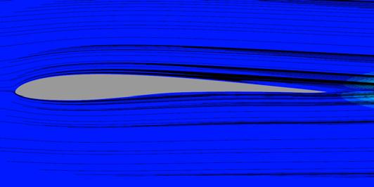
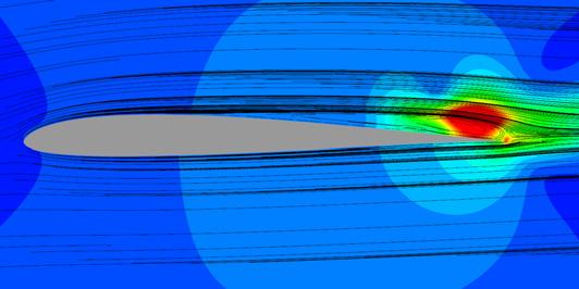
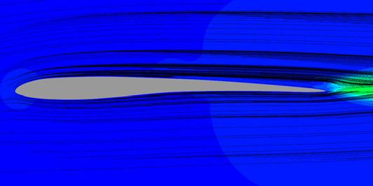
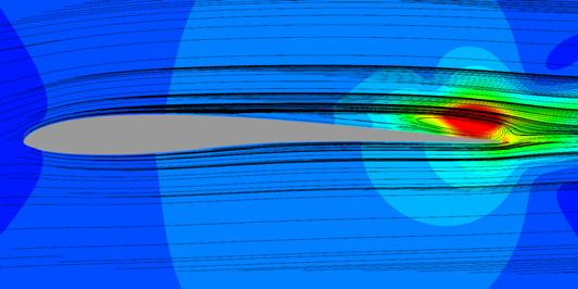
8 at each angle of attack look qualitatively similar. hus, we highlight common features and difference observed in instantaneous flow fields. he difference of flow fields around the wings is clearly seen at the angle of attack of 3. Although the flow past the Ishii wing shows two-dimensional coherent vortical structures in the wake, the flow around the D7003 and the D7003-Ishii wings presents formation and development of vortices in the suction side. he vortex structure observed in the suction side around the mid-span is a twodimensional coherent vortex. Gradually it breaks down and forms hair-pin like vortical structure near the trailing edge (vortices are colored by red or blue in Figure 7). Common features can be seen in the flow near the leading edge and the process of vortex formation and development in the suction side of the wing. Especially, at high angles of attack the difference of the airfoil shape has little influence in the instantaneous flow structure around the wings due to the fully separated from the leading edge (e.g. AoA= 6 in Figure 7) AoA (a) D7003 (b) Ishii (c) D7003-Ishii Figure 7: napshots of instantaneous flow fields around an D7003, an Ishii, and an D7003-Ishii wings. Iso-surfaces indicate the invariant of the velocity gradient (Q= 5) and its color shows streamwise vorticity (range: -5 to 5) 8


 D7003 R (b) Ishii R (c) D7003-Ishii Figure 8: Averaged stream-wise velocity contour and streamlines around three")
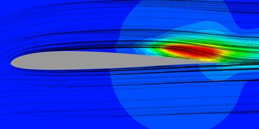
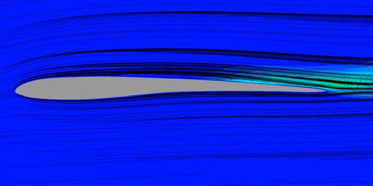
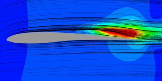
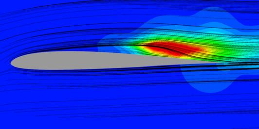
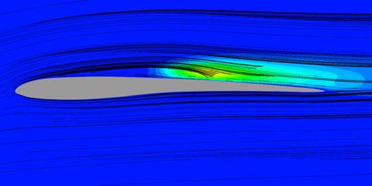
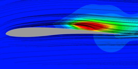
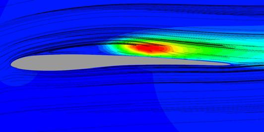
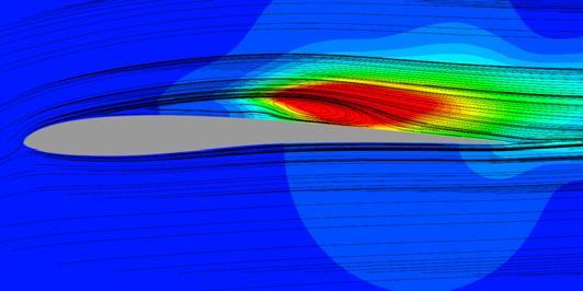
9 4.2 Averaged flow fields and surface pressure distributions Figure 8 shows phase- and spanwise-averaged flow for several angles of attack with computed separation, transition, and reattachment points that are denoted as,, and R. Note that the average fields and surface skin friction and pressure distribution are computed by averaging the solution over a non-dimensional time of 50c/a and then performing a spatial average over all spanwise planes. At the angle of attack of 0, the flow attaches on all wings. When the angle of attack becomes 3, the region where the flow separates around the D7003 and the D7003-Ishii wing (blue color region in Figure 8) is gradually expanded and moves toward the leading edge compared with those at low angles of attack. At the angle of attack of 4, a long LB is observed in the suction side of the wings. Moreover, it is clearly seen that larger and longer LB existed on the suction side of the D7003 and the D7003-Ishii wings than that of the Ishii wing. From the angles of attack of 5 to 6, the length of LB of the D7003 and the D7003-Ishii wings reduce while that of the Ishii wing increases R R R 5 R R R R 6 AoA (a) D7003 R (b) Ishii R (c) D7003-Ishii Figure 8: Averaged stream-wise velocity contour and streamlines around three wings. Contour ranges from 0.0 to hree points with notifications,, and R indicate the location of separation, laminar-to-turbulence transition, and reattachment point. 9
10 In order to gain further understanding of fluid physics including the LBs, separation and reattachment, the surface pressure distributions are plotted in Figure 9 and Figure 10. It is noted that the locations of those points are estimated based on the averaged skin friction coefficient distribution. It shows that from the angle of attack of 4 up to 6 the LBs are present for all wings. Furthermore all wings experience the laminar separation near the trailing edge at low angles of attack, the laminar separation at the leading edge and reattachment near the trailing edge (i.e. formation of the LB) at intermediate angles of attack, and then the laminar separation at the leading edge at high angles of attack. For all wings magnitude of suction peak increases with the angle of attack increases and similar peak values are observed. For the D7003-Ishii wing, it is found that the averaged upper surface pressure distribution of the D7003-Ishii wing are similar to that of the D7003 airfoil as well as the averaged lower surface pressure distribution of the D7003-Ishii wing are similar to that of the Ishii airfoil. his result implies that the change of airfoil cross-sectional shape does not significantly affect surface pressure distributions of each surface and the flow along with the lower surface. Furthermore, the length of the LB decreases with the angle of attack increases up to 5. However, the length of the LB observed around the Ishii wing becomes similar to those observed in the D7003 and the D7003-Ishii wing because the location of reattachment point moves to trailing edge. his movement of reattachment point might be because the Ishii airfoil has flatter upper surface than that of the D7003 airfoil. imilar dynamic behavior of the LB is observed around the flat plate at the Reynolds number of 10 3 [16]. Figure 9: Phase- and spanwise-averaged surface pressure coefficient distribution for (a) the D7003, (b) the Ishii, and (c) the D7003 wings. 10


11 Figure 10: Location of computed separation and reattachment point AoA (a) D7003 (b) Ishii (c) D7003-Ishii Figure 11: Phase- and spanwise-averaged turbulence kinetic energy and streamlines around three airfoils. indicates the transition point. 11
12 Figure 11 shows the phase- and spanwise-averaged turbulence kinetic energy (KE) distribution around the wings. he high KE region corresponds to the position where the three-dimensional hairpin vortex is generated by the deformation of two-dimensional vortex (see Figure 7). After the transition occurs in the LB high KE region can be observed for the angle of attack of 4, 5, and 6. his observation is consistent with the previous reports [1, 4]. As noted, the Ishii airfoil shows laminar-to-turbulent transition at higher angler of attack than the D7003 airfoil one. 4.3 Averaged aerodynamic performances he aerodynamic force coefficients as function of the angle of attack are plotted in Figure 12, Figure 13, and Figure 14. It should be noted that the angle of attack used in this study is the geometric angle of attack with respect to freestream and is not increment from the zero-lift angle of attack for each airfoil. From three figures several features are pointed out: (i) the lower surface shape of the Ishii airfoil increases lift generation without increase of the drag; (ii) the upper surface of the airfoil is a dominant factor for the drag generation at the angle of attack ranging between 0 and 5 ; (iii) the change in lift slope from the angle of attack of 3 to 4 is observed; and (vi) at same angle of attack all wings attain maximum lift-to-drag ratio and the Ishii airfoil shows best performance in terms of the lift-to-drag ratio due to the smallest drag and medium lift. Figure 12: Mean lift (left) and drag (right) coefficients for three wings as function of angle of attack. 12
13 Figure 13: Lift-to-drag ratio of three wings against the angle of attack. Figure 14: Comparison of phase- and spanwise-averaged surface pressure coefficient distribution: (a) AoA= 0, (b) AoA= 3, (c) AoA= 4, (d) AoA= 5, and (e) AoA= 6. 13
14 Looking at the surface pressure distributions of the D7003 and the D7003-Ishii wing as shown in Figure 14, although the pressure distribution of upper surface of both airfoils are almost same including the region of plateau, the pressure distribution of lower surface are clearly different. his suggests that the greater positive curvature of the lower surface of the Ishii airfoil helps to increase lift generation. Note its influence is also observed in the pressure distribution near the trailing edge. Furthermore the reasons that the D7003-Ishii wing generates largest lift at the angles of attack of 4 are 5 are the presence of longer LB than that of Ishii wing and the positive camber of lower surface. In addition, the formation of the long LB is strongly related to the point (iii) [10]. he characteristic of a long LB is seen in the plateau of the pressure distribution at the angle of attack of 4. It leads to increase not only in lift but also in drag. 5 Concluding Remarks he effects of airfoil shape on low Reynolds number aerodynamics are numerically investigated. he flowfield around the wing is obtained by numerically solving Navier-tokes equations. In order to compute unsteady turbulent flow with certain accuracy we perform the large-eddy simulations with 6 th -order compact finite difference scheme and 10 th -order low pass filter, and 2 nd -order backward implicit time integration with inner iterations. ystematic numerical excesses show the feasibility of current simulations to predict flow fields around fixed-wing configurations involving a laminar separation and laminar-to-turbulence transition at low Reynolds number. At the Reynolds number of , two types of thin and asymmetric airfoils are considered. he results show that the upper surface of airfoil shape affects the formation of an LB and the transition to turbulence in the threedimensional flow around the wings and the lower surface of airfoil shape does not significantly affect the flow structures around the airfoil, however, it can help to increase lift generation if its shape is designed appropriately. herefore significant influence in the aerodynamic performance is observed. References [1].J. Mueller (ed.), Fixed and Flapping Wing Aerodynamics for Micro Air Vehicle Applications, American Institute of Aeronautics and Astronautics, Inc., Reston, VA, U..A., [2] W. hyy, Y. Lian, J. ang, D. Viieru, H. Liu, Aerodynamics of Low Reynolds Number Flyers, Cambridge University Press, New York, NY, U..A., [3] F. W. chmitz, he Aerodynamics of mall Reynolds Number, NAA M- 51, [4] P. B.. Lissaman, Low-Reynolds-Number Airfoils, Annual Review in Fluid Mechanics, 15, ,
15 [5] M.. elig, J.F. Donovan, D.B. Fraser, Airfoils at Low peeds, oartech 8, H.A. tokely Publisher: Virginia Beach, VA, U..A., [6] M.. elig, J.J Guglielmo, A.P. Groeren, P. Giguere, ummary of Low-speed Airfoil Data, oartech Aero Publications, H.A. tokely: Virginia Beach, VA, U..A., [7] M. Anyoji,. Nonomura, A. Oyama, K. Fujii, K. Nose, D. Numata, H. Nagai, K. Asai, Aerodynamic Characteristics of Ishii Airfoil at Low Reynolds Numbers, Proceeding of Eighth International Conference on Flow Dynamics, endai, Miyagi, Japan, [8] M. C. Galbraith, M. R. Visbal, Implicit Large-eddy imulation of low Reynolds Number Flow Past the D7003 Airfoil, Forty-sixth AIAA Aerospace ciences Meeting and Exhibit, Reno, NV, U..A., AIAA , [9] A. Uranga, P.-O. Persson, M. Drela, J. Peraire, Implicit Large Eddy imulation of ransition to urbulence at Low Reynolds Numbers Using a Discontinuous Galerkin Method, International Journal For Numerical Methods in Engineering, 87, , [10] R. Kojima,. Nonomura, A. Oyama, K. Fujii, Computational tudy of Flow Characteristics of hick and hin Airfoil with Implicit Large-eddy imulation at Low Reynolds Number, Proceedings of AME-JME-KME Joint Fluids Engineering Conference 2011, Hamamatsu, hizuoka, Japan, [11] K. Fujii,. Obayashi, High-resolution upwind scheme for vortical-flow simulations, Journal of Aircraft, 26, , [12]. K. Lele, Compact Finite Difference cheme with pectral-like Resolution, Journal of Computational Physics, 103, 16-22, [13] D. V. Gaitonde, M. R. Visbal, Pade ype Higher-order Boundary Filters for the Navier-tokes Equations, 38, , [14] H. Nishida,. Nonomura, ADI-G cheme on Ideal Magnetohydrodynamics, Journal of Computational Physics, 228, , [15]. R. Chakravarthy, Relaxation Methods for Unfactored Implicit Upwind chemes, twenty-second Aerospace ciences Meeting, Reno, NV, U..A., AIAA , [16] M. Anyoji, Development of a Mars Wing unnel and Its Applications to Low Reynolds Number and High-subsonic Airfoil esting, Ph.D dissertation, ohoku University, Japan,
COMPUTATIONAL STUDY OF SEPARATION CONTROL MECHANISM WITH THE IMAGINARY BODY FORCE ADDED TO THE FLOWS OVER AN AIRFOIL
 COMPUTATIONAL STUDY OF SEPARATION CONTROL MECHANISM WITH THE IMAGINARY BODY FORCE ADDED TO THE FLOWS OVER AN AIRFOIL Kengo Asada 1 and Kozo Fujii 2 ABSTRACT The effects of body force distribution on the
COMPUTATIONAL STUDY OF THE SYNTHETIC JET ON SEPARATED FLOW OVER A BACKWARD-FACING STEP. Kozo Fujii
 ASME 1 International Mechanical Engineering Congress & Exposition IMECE1 November 1-18, Vancouver, British Colombia, Canada IMECE1-38767 COMPUTATIONAL STUDY OF THE SYNTHETIC JET ON SEPARATED FLOW OVER
Given the water behaves as shown above, which direction will the cylinder rotate?
 water stream fixed but free to rotate Given the water behaves as shown above, which direction will the cylinder rotate? ) Clockwise 2) Counter-clockwise 3) Not enough information F y U 0 U F x V=0 V=0
Numerical Simulation of Flow Separation Control using Multiple DBD Plasma Actuators
 Journal of Applied Fluid Mechanics, Vol. 9, No. 4, pp. 1865-1875, 2016. Available online at www.jafmonline.net, ISSN 1735-3572, EISSN 1735-3645. DOI: 10.18869/acadpub.jafm.68.235.25325 Numerical Simulation
Burst Frequency effect of DBD Plasma actuator on the control of separated flow over an airfoil
 24 Burst Frequency effect of DBD Plasma actuator on the control of separated flow over an airfoil,, 252-5210 3-1-1, asada@flab.isas.jaxa.jp, ISAS/JAXA, 252-5210 3-1-1, fujii@flab.isas.jaxa.jp Kengo Asada,
COMPUTATIONAL SIMULATION OF THE FLOW PAST AN AIRFOIL FOR AN UNMANNED AERIAL VEHICLE
 COMPUTATIONAL SIMULATION OF THE FLOW PAST AN AIRFOIL FOR AN UNMANNED AERIAL VEHICLE L. Velázquez-Araque 1 and J. Nožička 2 1 Division of Thermal fluids, Department of Mechanical Engineering, National University
344 JAXA Special Publication JAXA-SP E 2. Prediction by the CFD Approach 2.1 Numerical Procedure The plane shape of the thin delta wing of the r
 5th Symposium on Integrating CFD and Experiments in Aerodynamics (Integration 2012) 343 Aerodynamic Characteristics of a Delta Wing with Arc Camber for Mars Exploration Takao Unoguchi,* 1 Shogo Aoyama,*
SIMULATION OF GAS FLOW OVER MICRO-SCALE AIRFOILS USING A HYBRID CONTINUUM-PARTICLE APPROACH
 33rd AIAA Fluid Dynamics Conference and Exhibit 3-6 June 3, Orlando, Florida AIAA 3-44 33 rd AIAA Fluid Dynamics Conference and Exhibit / Orlando, Florida / 3-6 Jun 3 SIMULATION OF GAS FLOW OVER MICRO-SCALE
Implicit Large Eddy Simulation of Transitional Flow over a SD7003 Wing Using High-order Spectral Difference Method
 40th Fluid Dynamics Conference and Exhibit 28 June - 1 July 2010, Chicago, Illinois AIAA 2010-4442 Implicit Large Eddy Simulation of Transitional Flow over a SD7003 Wing Using High-order Spectral Difference
저작권법에따른이용자의권리는위의내용에의하여영향을받지않습니다.
 저작자표시 - 비영리 - 변경금지 2.0 대한민국 이용자는아래의조건을따르는경우에한하여자유롭게 이저작물을복제, 배포, 전송, 전시, 공연및방송할수있습니다. 다음과같은조건을따라야합니다 : 저작자표시. 귀하는원저작자를표시하여야합니다. 비영리. 귀하는이저작물을영리목적으로이용할수없습니다. 변경금지. 귀하는이저작물을개작, 변형또는가공할수없습니다. 귀하는, 이저작물의재이용이나배포의경우,
Numerical study of battle damaged two-dimensional wings
 Advances in Fluid Mechanics IX 141 Numerical study of battle damaged two-dimensional wings S. Djellal, T. Azzam, M. Djellab & K. Lakkaichi Fluid Mechanics Laboratory Polytechnical School Bordj El Bahri,
Large-eddy simulations for wind turbine blade: rotational augmentation and dynamic stall
 Large-eddy simulations for wind turbine blade: rotational augmentation and dynamic stall Y. Kim, I.P. Castro, and Z.T. Xie Introduction Wind turbines operate in the atmospheric boundary layer and their
FEDSM COMPUTATIONAL AEROACOUSTIC ANALYSIS OF OVEREXPANDED SUPERSONIC JET IMPINGEMENT ON A FLAT PLATE WITH/WITHOUT HOLE
 Proceedings of FEDSM2007: 5 th Joint ASME/JSME Fluids Engineering Conference July 30-August 2, 2007, San Diego, CA, USA FEDSM2007-37563 COMPUTATIONAL AEROACOUSTIC ANALYSIS OF OVEREXPANDED SUPERSONIC JET
Wall treatments and wall functions
 Wall treatments and wall functions A wall treatment is the set of near-wall modelling assumptions for each turbulence model. Three types of wall treatment are provided in FLUENT, although all three might
Part 3. Stability and Transition
 Part 3 Stability and Transition 281 Overview T. Cebeci 1 Recent interest in the reduction of drag of underwater vehicles and aircraft components has rekindled research in the area of stability and transition.
INFLUENCE OF ACOUSTIC EXCITATION ON AIRFOIL PERFORMANCE AT LOW REYNOLDS NUMBERS
 ICAS 2002 CONGRESS INFLUENCE OF ACOUSTIC EXCITATION ON AIRFOIL PERFORMANCE AT LOW REYNOLDS NUMBERS S. Yarusevych*, J.G. Kawall** and P. Sullivan* *Department of Mechanical and Industrial Engineering, University
Masters in Mechanical Engineering Aerodynamics 1 st Semester 2015/16
 Masters in Mechanical Engineering Aerodynamics st Semester 05/6 Exam st season, 8 January 06 Name : Time : 8:30 Number: Duration : 3 hours st Part : No textbooks/notes allowed nd Part : Textbooks allowed
Introduction to Atmospheric Flight. Dr. Guven Aerospace Engineer (P.hD)
") Introduction to Atmospheric Flight Dr. Guven Aerospace Engineer (P.hD) What is Atmospheric Flight? There are many different ways in which Aerospace engineering is associated with atmospheric flight concepts.
Introduction to Atmospheric Flight Dr. Guven Aerospace Engineer (P.hD) What is Atmospheric Flight? There are many different ways in which Aerospace engineering is associated with atmospheric flight concepts.
OpenFOAM Simulations for MAV Applications
 16 th Annual CFD Symposium 11th-12th August 2014, Bangalore 1 OpenFOAM Simulations for MAV Applications Syed Zahid*, A. Rajesh, M.B. Subrahmanya, B.N. Rajani *Student, Dept. of Mech. Engg, SDM, Dharwad,
Active Control of Separated Cascade Flow
 Chapter 5 Active Control of Separated Cascade Flow In this chapter, the possibility of active control using a synthetic jet applied to an unconventional axial stator-rotor arrangement is investigated.
Effect of Flow-Acoustic Resonant Interactions on Aerodynamic Response of Transitional Airfoils
 Dissertations and Theses 12-2016 Effect of Flow-Acoustic Resonant Interactions on Aerodynamic Response of Transitional Airfoils Joseph Hayden Follow this and additional works at: https://commons.erau.edu/edt
A Multi-Dimensional Limiter for Hybrid Grid
 APCOM & ISCM 11-14 th December, 2013, Singapore A Multi-Dimensional Limiter for Hybrid Grid * H. W. Zheng ¹ 1 State Key Laboratory of High Temperature Gas Dynamics, Institute of Mechanics, Chinese Academy
Masters in Mechanical Engineering. Problems of incompressible viscous flow. 2µ dx y(y h)+ U h y 0 < y < h,
+ U h y 0 < y < h,") Masters in Mechanical Engineering Problems of incompressible viscous flow 1. Consider the laminar Couette flow between two infinite flat plates (lower plate (y = 0) with no velocity and top plate (y =
Masters in Mechanical Engineering Problems of incompressible viscous flow 1. Consider the laminar Couette flow between two infinite flat plates (lower plate (y = 0) with no velocity and top plate (y =
Mestrado Integrado em Engenharia Mecânica Aerodynamics 1 st Semester 2012/13
 Mestrado Integrado em Engenharia Mecânica Aerodynamics 1 st Semester 212/13 Exam 2ª época, 2 February 213 Name : Time : 8: Number: Duration : 3 hours 1 st Part : No textbooks/notes allowed 2 nd Part :
The Simulation of Wraparound Fins Aerodynamic Characteristics
 The Simulation of Wraparound Fins Aerodynamic Characteristics Institute of Launch Dynamics Nanjing University of Science and Technology Nanjing Xiaolingwei 00 P. R. China laithabbass@yahoo.com Abstract:
FLOW OVER NACA-4415 AEROFOIL AT EXTREME REYNOLDS NUMBERS
 FLOW OVER NACA-4415 AEROFOIL AT EXTREME REYNOLDS NUMBERS Kamma Pradeep 1, Enugurthi Manasa 2, Adimulam Neha 3 1, 2, 3 Student, Mechanical Engineering, CVR College of Engineering (India) ABSTRACT Computational
WALL ROUGHNESS EFFECTS ON SHOCK BOUNDARY LAYER INTERACTION FLOWS
 ISSN (Online) : 2319-8753 ISSN (Print) : 2347-6710 International Journal of Innovative Research in Science, Engineering and Technology An ISO 3297: 2007 Certified Organization, Volume 2, Special Issue
Large-eddy simulation of jet mixing in a supersonic turbulent crossflow
 Center for Turbulence Research Annual Research Briefs 8 9 Large-eddy simulation of jet mixing in a supersonic turbulent crossflow By S. Kawai AN S. K. Lele. Motivation and objectives Important recent research
INSTITUTE OF AERONAUTICAL ENGINEERING (Autonomous) Dundigal, Hyderabad
 Dundigal, Hyderabad") INSTITUTE OF AERONAUTICAL ENGINEERING (Autonomous) Dundigal, Hyderabad - 500 043 AERONAUTICAL ENGINEERING TUTORIAL QUESTION BANK Course Name : LOW SPEED AERODYNAMICS Course Code : AAE004 Regulation : IARE
INSTITUTE OF AERONAUTICAL ENGINEERING (Autonomous) Dundigal, Hyderabad - 500 043 AERONAUTICAL ENGINEERING TUTORIAL QUESTION BANK Course Name : LOW SPEED AERODYNAMICS Course Code : AAE004 Regulation : IARE
Explicit algebraic Reynolds stress models for internal flows
 5. Double Circular Arc (DCA) cascade blade flow, problem statement The second test case deals with a DCA compressor cascade, which is considered a severe challenge for the CFD codes, due to the presence
Brenda M. Kulfan, John E. Bussoletti, and Craig L. Hilmes Boeing Commercial Airplane Group, Seattle, Washington, 98124
 AIAA--2007-0684 Pressures and Drag Characteristics of Bodies of Revolution at Near Sonic Speeds Including the Effects of Viscosity and Wind Tunnel Walls Brenda M. Kulfan, John E. Bussoletti, and Craig
HISTORY EFFECTS FOR CAMBERED AND SYMMETRIC
 HISTORY EFFECTS FOR CAMBERED AND SYMMETRIC WING PROFILES A. Tanarro, R. Vinuesa and P. Schlatter Linné FLOW Centre, KTH Mechanics and Swedish e-science Research Centre (SeRC), SE-1 44 Stockholm, Sweden
Chapter 3 Lecture 8. Drag polar 3. Topics. Chapter-3
 Chapter 3 ecture 8 Drag polar 3 Topics 3.2.7 Boundary layer separation, adverse pressure gradient and favourable pressure gradient 3.2.8 Boundary layer transition 3.2.9 Turbulent boundary layer over a
1. Introduction, tensors, kinematics
 1. Introduction, tensors, kinematics Content: Introduction to fluids, Cartesian tensors, vector algebra using tensor notation, operators in tensor form, Eulerian and Lagrangian description of scalar and
Numerical Investigation of Shock wave Turbulent Boundary Layer Interaction over a 2D Compression Ramp
 Advances in Aerospace Science and Applications. ISSN 2277-3223 Volume 4, Number 1 (2014), pp. 25-32 Research India Publications http://www.ripublication.com/aasa.htm Numerical Investigation of Shock wave
Investigation of Co-Flow Jet Airfoil Mixing Mechanism Using Large Eddy Simulation
 4st AIAA Fluid Dynamics Conference and Exhibit 27-3 June 2, Honolulu, Hawaii AIAA 2-398 Investigation of Co-Flow Jet Airfoil Mixing Mechanism Using Large Eddy Simulation Hong-Sik IM, Ge-Cheng Zha, Bertrand
AN ABSTRACT OF THE THESIS OF
 AN ABSTRACT OF THE THESIS OF Kevin J. Drost for the degree of Honors Baccalaureate of Science in Mechanical Engineering presented May 21, 2010. Title: Direct Numerical Simulation of a Flat Wing with a
Turbulent Boundary Layers & Turbulence Models. Lecture 09
 Turbulent Boundary Layers & Turbulence Models Lecture 09 The turbulent boundary layer In turbulent flow, the boundary layer is defined as the thin region on the surface of a body in which viscous effects
SPC Aerodynamics Course Assignment Due Date Monday 28 May 2018 at 11:30
 SPC 307 - Aerodynamics Course Assignment Due Date Monday 28 May 2018 at 11:30 1. The maximum velocity at which an aircraft can cruise occurs when the thrust available with the engines operating with the
NUMERICAL STUDY OF THE AERODYNAMIC PERFORMANCE OF NACA 0012 IN THE PRESENCE OF AN UNSTEADY HEAT SOURCE
 NUMERICAL STUDY OF THE AERODYNAMIC PERFORMANCE OF NACA 0012 IN THE PRESENCE OF AN UNSTEADY HEAT SOURCE M.A. Mendez Soto, D.P. Porfiriev Samara National Research University, Samara, Russia Abstract. The
Detached Eddy Simulation on Hypersonic Base Flow Structure of Reentry-F Vehicle
 Available online at www.sciencedirect.com ScienceDirect Procedia Engineering 00 (2014) 000 000 www.elsevier.com/locate/procedia APISAT2014, 2014 Asia-Pacific International Symposium on Aerospace Technology,
ADVERSE REYNOLDS NUMBER EFFECT ON MAXIMUM LIFT OF TWO DIMENSIONAL AIRFOILS
 ICAS 2 CONGRESS ADVERSE REYNOLDS NUMBER EFFECT ON MAXIMUM LIFT OF TWO DIMENSIONAL AIRFOILS Kenji YOSHIDA, Masayoshi NOGUCHI Advanced Technology Aircraft Project Center NATIONAL AEROSPACE LABORATORY 6-
Analysis of Shock Motion in STBLI Induced by a Compression Ramp Configuration Using DNS Data
 45th AIAA Aerospace Science Meeting and Exhibit, January 8 11, 25/Reno, Nevada Analysis of Shock Motion in STBLI Induced by a Compression Ramp Configuration Using DNS Data M. Wu and M.P. Martin Mechanical
Preliminary Study of the Turbulence Structure in Supersonic Boundary Layers using DNS Data
 35th AIAA Fluid Dynamics Conference, June 6 9, 2005/Toronto,Canada Preliminary Study of the Turbulence Structure in Supersonic Boundary Layers using DNS Data Ellen M. Taylor, M. Pino Martín and Alexander
Aerodynamic Investigation of a 2D Wing and Flows in Ground Effect
 26 2 2009 3 CHINESE JOURNAL OF COMPUTATIONAL PHYSICS Vol. 26,No. 2 Mar., 2009 Article ID : 10012246 X(2009) 0220231210 Aerodynamic Investigation of a 2D Wing and Flows in Ground Effect YANG Wei, YANG Zhigang
Validation 3. Laminar Flow Around a Circular Cylinder
 Validation 3. Laminar Flow Around a Circular Cylinder 3.1 Introduction Steady and unsteady laminar flow behind a circular cylinder, representing flow around bluff bodies, has been subjected to numerous
Numerical study of the effects of trailing-edge bluntness on highly turbulent hydro-foil flows
 Numerical study of the effects of trailing-edge bluntness on highly turbulent hydro-foil flows T. Do L. Chen J. Tu B. Anderson 7 November 2005 Abstract Flow-induced noise from fully submerged lifting bodies
Numerical Investigation of the Transonic Base Flow of A Generic Rocket Configuration
 1 Numerical Investigation of the Transonic Base Flow of A Generic Rocket Configuration A. Henze, C. Glatzer, M. Meinke, W. Schröder Institute of Aerodynamics, RWTH Aachen University, Germany March 21,
Numerical Methods in Aerodynamics. Turbulence Modeling. Lecture 5: Turbulence modeling
 Turbulence Modeling Niels N. Sørensen Professor MSO, Ph.D. Department of Civil Engineering, Alborg University & Wind Energy Department, Risø National Laboratory Technical University of Denmark 1 Outline
CFD COMPUTATION OF THE GROUND EFFECT ON AIRPLANE WITH HIGH ASPECT RATIO WING
 28 TH INTERNATIONAL CONGRESS OF THE AERONAUTICAL SCIENCES CFD COMPUTATION OF THE GROUND EFFECT ON AIRPLANE WITH HIGH ASPECT RATIO WING Sun Tae Kim*, Youngtae Kim**, Tae Kyu Reu* *Agency for Defense Development,
On the Aerodynamic Performance of Dragonfly Wing Section in Gliding Mode
 Advances in Aerospace Science and Applications. ISSN 2277-3223 Volume 3, Number 3 (2013), pp. 227-234 Research India Publications http://www.ripublication.com/aasa.htm On the Aerodynamic Performance of
AIRFRAME NOISE MODELING APPROPRIATE FOR MULTIDISCIPLINARY DESIGN AND OPTIMIZATION
 AIRFRAME NOISE MODELING APPROPRIATE FOR MULTIDISCIPLINARY DESIGN AND OPTIMIZATION AIAA-2004-0689 Serhat Hosder, Joseph A. Schetz, Bernard Grossman and William H. Mason Virginia Tech Work sponsored by NASA
Study on lattice Boltzmann method/ large eddy simulation and its application at high Reynolds number flow
 Research Article Study on lattice Boltzmann method/ large eddy simulation and its application at high Reynolds number flow Advances in Mechanical Engineering 1 8 Ó The Author(s) 2015 DOI: 10.1177/1687814015573829
Simulating Drag Crisis for a Sphere Using Skin Friction Boundary Conditions
 Simulating Drag Crisis for a Sphere Using Skin Friction Boundary Conditions Johan Hoffman May 14, 2006 Abstract In this paper we use a General Galerkin (G2) method to simulate drag crisis for a sphere,
Application of turbulence. models to high-lift airfoils. By Georgi Kalitzin
 Center for Turbulence Research Annual Research Briefs 997 65 Application of turbulence models to high-lift airfoils By Georgi Kalitzin. Motivation and objectives Accurate prediction of the ow over an airfoil
A Non-Intrusive Polynomial Chaos Method For Uncertainty Propagation in CFD Simulations
 An Extended Abstract submitted for the 44th AIAA Aerospace Sciences Meeting and Exhibit, Reno, Nevada January 26 Preferred Session Topic: Uncertainty quantification and stochastic methods for CFD A Non-Intrusive
Direct comparison between RANS turbulence model and fully-resolved LES
 International Journal of Gas Turbine, Propulsion and Power Systems July 2016, Volume 8, Number 2 Direct comparison between RANS turbulence model and fully-resolved LES Takuya Ouchi 1 Susumu Teramoto 2
2-D and 3-D Assessment of Cambered and Symmetric Airfoils: A CFD Study
 Clemson University TigerPrints All Theses Theses 12-2009 2-D and 3-D Assessment of Cambered and Symmetric Airfoils: A CFD Study Tuncay Kamas Clemson University, tkamas@clemson.edu Follow this and additional
1082. Computational study on aerodynamic characteristics of a flying wing MAV
 1082. Computational study on aerodynamic characteristics of a flying wing MAV Hongming Cai 1, Zhilin Wu 2, Tianhang Xiao 3, Shuanghou Deng 4 1, 2 School of Mechanical Engineering, Nanjing University of
Experimental Study on Flow Control Characteristics of Synthetic Jets over a Blended Wing Body Configuration
 Experimental Study on Flow Control Characteristics of Synthetic Jets over a Blended Wing Body Configuration Byunghyun Lee 1), Minhee Kim 1), Chongam Kim 1), Taewhan Cho 2), Seol Lim 3), and Kyoung Jin
SENSITIVITY ANALYSIS OF THE FACTORS AFFECTING FORCE GENERATION BY WING FLAPPING MOTION
 Proceedings of the ASME 2013 International Mechanical Engineering Congress and Exposition IMECE2013 November 15-21, 2013, San Diego, California, USA IMECE2013-65472 SENSITIVITY ANALYSIS OF THE FACTORS
Application of Dual Time Stepping to Fully Implicit Runge Kutta Schemes for Unsteady Flow Calculations
 Application of Dual Time Stepping to Fully Implicit Runge Kutta Schemes for Unsteady Flow Calculations Antony Jameson Department of Aeronautics and Astronautics, Stanford University, Stanford, CA, 94305
ME 425: Aerodynamics
 ME 45: Aerodynamics Dr. A.B.M. Toufique Hasan Professor Department of Mechanical Engineering Bangladesh University of Engineering & Technology (BUET), Dhaka Lecture-0 Introduction toufiquehasan.buet.ac.bd
DIRECT NUMERICAL SIMULATIONS OF HIGH SPEED FLOW OVER CAVITY. Abstract
 3 rd AFOSR International Conference on DNS/LES (TAICDL), August 5-9 th, 2001, Arlington, Texas. DIRECT NUMERICAL SIMULATIONS OF HIGH SPEED FLOW OVER CAVITY A. HAMED, D. BASU, A. MOHAMED AND K. DAS Department
Parallel Computation of Forced Vibration for A Compressor Cascade
 44th AIAA Aerospace Sciences Meeting and Exhibit 9-2 January 26, Reno, Nevada AIAA 26-628 AIAA Paper 26-628 Parallel Computation of Forced Vibration for A Compressor Cascade Zongjun Hu and Gecheng Zha
Research on Dynamic Stall and Aerodynamic Characteristics of Wind Turbine 3D Rotational Blade
 Research on Dynamic Stall and Aerodynamic Characteristics of Wind Turbine 3D Rotational Blade HU Guo-yu, SUN Wen-lei, Dong Ping The School of Mechanical Engineering Xinjiang University Urumqi, Xinjiang,
Two-Equation Turbulence Models for Turbulent Flow over a NACA 4412 Airfoil at Angle of Attack 15 Degree
 Two-Equation Turbulence Models for Turbulent Flow over a NACA 4412 Airfoil at Angle of Attack 15 Degree Omar Badran * Mechanical Engineering Department, Faculty of Engineering Technology, Al-Balqa` Applied
RECENT near-sonic and low-sonic boom transport aircraft
 JOURNAL OF AIRCRAFT Vol. 44, No. 6, November December 2007 Aerodynamic Characteristics of Bodies of Revolution at Near-Sonic Speeds Brenda M. Kulfan, John E. Bussoletti, and Craig L. Hilmes The Boeing
THE EFFECT OF INTERNAL ACOUSTIC EXCITATION ON THE AERODYNAMIC CHARACTERISTICS OF AIRFOIL AT HIGH ANGLE OF ATTACKE
 Vol.1, Issue.2, pp-371-384 ISSN: 2249-6645 THE EFFECT OF INTERNAL ACOUSTIC EXCITATION ON THE AERODYNAMIC CHARACTERISTICS OF AIRFOIL AT HIGH ANGLE OF ATTACKE Dr. Mohammed W. Khadim Mechanical Engineering
High Speed Aerodynamics. Copyright 2009 Narayanan Komerath
 Welcome to High Speed Aerodynamics 1 Lift, drag and pitching moment? Linearized Potential Flow Transformations Compressible Boundary Layer WHAT IS HIGH SPEED AERODYNAMICS? Airfoil section? Thin airfoil
CFD Analysis of Micro-Ramps for Hypersonic Flows Mogrekar Ashish 1, a, Sivakumar, R. 2, b
 Applied Mechanics and Materials Submitted: 2014-04-25 ISSN: 1662-7482, Vols. 592-594, pp 1962-1966 Revised: 2014-05-07 doi:10.4028/www.scientific.net/amm.592-594.1962 Accepted: 2014-05-16 2014 Trans Tech
Introduction to Turbulence AEEM Why study turbulent flows?
 Introduction to Turbulence AEEM 7063-003 Dr. Peter J. Disimile UC-FEST Department of Aerospace Engineering Peter.disimile@uc.edu Intro to Turbulence: C1A Why 1 Most flows encountered in engineering and
Lift Enhancement by Dynamically Changing Wingspan. in Forward Flapping Flight (09/10/2013)
") Lift Enhancement by Dynamically Changing Wingspan in Forward Flapping Flight Shizhao Wang 1, Xing Zhang 1, Guowei He 1a), ianshu Liu 2,1 (09/10/2013) 1 he State Key Laboratory of Nonlinear Mechanics, Institute
Lift Enhancement by Dynamically Changing Wingspan in Forward Flapping Flight Shizhao Wang 1, Xing Zhang 1, Guowei He 1a), ianshu Liu 2,1 (09/10/2013) 1 he State Key Laboratory of Nonlinear Mechanics, Institute
Available online at ScienceDirect. Procedia Engineering 79 (2014 ) 49 54
 49 54") Available online at www.sciencedirect.com ScienceDirect Procedia Engineering 79 (2014 ) 49 54 37th National Conference on Theoretical and Applied Mechanics (37th NCTAM 2013) & The 1st International Conference
Available online at www.sciencedirect.com ScienceDirect Procedia Engineering 79 (2014 ) 49 54 37th National Conference on Theoretical and Applied Mechanics (37th NCTAM 2013) & The 1st International Conference
Experimental Verification of CFD Modeling of Turbulent Flow over Circular Cavities using FLUENT
 Experimental Verification of CFD Modeling of Turbulent Flow over Circular Cavities using FLUENT T Hering, J Dybenko, E Savory Mech. & Material Engineering Dept., University of Western Ontario, London,
Aerodynamics. High-Lift Devices
 High-Lift Devices Devices to increase the lift coefficient by geometry changes (camber and/or chord) and/or boundary-layer control (avoid flow separation - Flaps, trailing edge devices - Slats, leading
1. Fluid Dynamics Around Airfoils
 1. Fluid Dynamics Around Airfoils Two-dimensional flow around a streamlined shape Foces on an airfoil Distribution of pressue coefficient over an airfoil The variation of the lift coefficient with the
Large eddy simulation of turbulent flow over a backward-facing step: effect of inflow conditions
 June 30 - July 3, 2015 Melbourne, Australia 9 P-26 Large eddy simulation of turbulent flow over a backward-facing step: effect of inflow conditions Jungwoo Kim Department of Mechanical System Design Engineering
Resolving the dependence on free-stream values for the k-omega turbulence model
 Resolving the dependence on free-stream values for the k-omega turbulence model J.C. Kok Resolving the dependence on free-stream values for the k-omega turbulence model J.C. Kok This report is based on
SIMULATION OF THREE-DIMENSIONAL INCOMPRESSIBLE CAVITY FLOWS
 ICAS 2000 CONGRESS SIMULATION OF THREE-DIMENSIONAL INCOMPRESSIBLE CAVITY FLOWS H Yao, R K Cooper, and S Raghunathan School of Aeronautical Engineering The Queen s University of Belfast, Belfast BT7 1NN,
Y. Abe, N. Iizuka, T. Nonomura, K. Fujii Corresponding author:
 Seventh International Conference on Computational Fluid Dynamics (ICCFD7), Big Island, Hawaii, July 9-13, 2012 ICCFD7-2012-2801 ICCFD7-2801 Symmetric-conservative metric evaluations for higher-order finite
Simulation of Aeroelastic System with Aerodynamic Nonlinearity
 Simulation of Aeroelastic System with Aerodynamic Nonlinearity Muhamad Khairil Hafizi Mohd Zorkipli School of Aerospace Engineering, Universiti Sains Malaysia, Penang, MALAYSIA Norizham Abdul Razak School
Aerodynamic force analysis in high Reynolds number flows by Lamb vector integration
 Aerodynamic force analysis in high Reynolds number flows by Lamb vector integration Claudio Marongiu, Renato Tognaccini 2 CIRA, Italian Center for Aerospace Research, Capua (CE), Italy E-mail: c.marongiu@cira.it
CHAPTER 4 OPTIMIZATION OF COEFFICIENT OF LIFT, DRAG AND POWER - AN ITERATIVE APPROACH
 82 CHAPTER 4 OPTIMIZATION OF COEFFICIENT OF LIFT, DRAG AND POWER - AN ITERATIVE APPROACH The coefficient of lift, drag and power for wind turbine rotor is optimized using an iterative approach. The coefficient
Coupled Fluid and Heat Flow Analysis Around NACA Aerofoil Profiles at Various Mach Numbers
 International Journal of Engineering Research and Technology. ISSN 0974-3154 Volume 6, Number 2 (2013), pp. 249-258 International Research Publication House http://www.irphouse.com Coupled Fluid and Heat
Contents. I Introduction 1. Preface. xiii
 Contents Preface xiii I Introduction 1 1 Continuous matter 3 1.1 Molecules................................ 4 1.2 The continuum approximation.................... 6 1.3 Newtonian mechanics.........................
Lecture 7 Boundary Layer
 SPC 307 Introduction to Aerodynamics Lecture 7 Boundary Layer April 9, 2017 Sep. 18, 2016 1 Character of the steady, viscous flow past a flat plate parallel to the upstream velocity Inertia force = ma
Near-wall Reynolds stress modelling for RANS and hybrid RANS/LES methods
 Platzhalter für Bild, Bild auf Titelfolie hinter das Logo einsetzen Near-wall Reynolds stress modelling for RANS and hybrid RANS/LES methods Axel Probst (now at: C 2 A 2 S 2 E, DLR Göttingen) René Cécora,
AERODYNAMICS OF WINGS AT LOW REYNOLDS NUMBERS. John McArthur. A Qualifying Exam Proposal Presented to the FACULTY OF THE GRADUATE SCHOOL
 AERODYNAMICS OF WINGS AT LOW REYNOLDS NUMBERS by John McArthur A Qualifying Exam Proposal Presented to the FACULTY OF THE GRADUATE SCHOOL UNIVERSITY OF SOUTHERN CALIFORNIA In Partial Fulfillment of the
Department of Mechanical Engineering
 Department of Mechanical Engineering AMEE401 / AUTO400 Aerodynamics Instructor: Marios M. Fyrillas Email: eng.fm@fit.ac.cy HOMEWORK ASSIGNMENT #2 QUESTION 1 Clearly there are two mechanisms responsible
41st AIAA Aerospace Sciences Meeting and Exhibit January 6 9, 2003/Reno, NV
 AIAA 3 267 Calculation of Unsteady Transonic Flow by an Euler Method with Small Perturbation Boundary Conditions C. Gao, S. Luo, F. Liu Department of Mechanical and Aerospace Engineering University of
Optimization of Flapping Airfoils for Maximum Thrust and Propulsive Efficiency I. H. Tuncer, M. Kay
 Czech Technical University in Prague Acta Polytechnica Vol. 44 No. 1/2004 Optimization of Flapping Airfoils for Maximum Thrust and Propulsive Efficiency I. H. Tuncer, M. Kay A numerical optimization algorithm
Definitions. Temperature: Property of the atmosphere (τ). Function of altitude. Pressure: Property of the atmosphere (p). Function of altitude.
. Function of altitude. Pressure: Property of the atmosphere (p). Function of altitude.") Definitions Chapter 3 Standard atmosphere: A model of the atmosphere based on the aerostatic equation, the perfect gas law, an assumed temperature distribution, and standard sea level conditions. Temperature:
Definitions Chapter 3 Standard atmosphere: A model of the atmosphere based on the aerostatic equation, the perfect gas law, an assumed temperature distribution, and standard sea level conditions. Temperature:
Implicit numerical scheme based on SMAC method for unsteady incompressible Navier-Stokes equations
 172 Pet.Sci.(28)5:172-178 DOI 1.17/s12182-8-27-z Implicit numerical scheme based on SMAC method for unsteady incompressible Navier-Stokes equations Li Zhenlin and Zhang Yongxue School of Mechanical and
Modeling of Pitching and Plunging Airfoils at Reynolds Number between and
 27th AIAA Applied Aerodynamics Conference 22-25 June 2009, San Antonio, Texas AIAA 2009-4100 Modeling of Pitching and Plunging Airfoils at Reynolds Number between 1 10 4 and 6 10 4 Chang-kwon Kang 1 *,
Investigation on Boundary Layer Ingestion Propulsion for UAVs
 International Micro Air Vehicle Conference and Flight Competition (IMAV) 2017 293 Investigation on Boundary Layer Ingestion Propulsion for UAVs L. Teperin, M. El-Salamony, A. Moharam, and M. Shehata, Central
1. Introduction Some Basic Concepts
 1. Introduction Some Basic Concepts 1.What is a fluid? A substance that will go on deforming in the presence of a deforming force, however small 2. What Properties Do Fluids Have? Density ( ) Pressure
BOUNDARY LAYER FLOWS HINCHEY
 BOUNDARY LAYER FLOWS HINCHEY BOUNDARY LAYER PHENOMENA When a body moves through a viscous fluid, the fluid at its surface moves with it. It does not slip over the surface. When a body moves at high speed,
AER1310: TURBULENCE MODELLING 1. Introduction to Turbulent Flows C. P. T. Groth c Oxford Dictionary: disturbance, commotion, varying irregularly
 1. Introduction to Turbulent Flows Coverage of this section: Definition of Turbulence Features of Turbulent Flows Numerical Modelling Challenges History of Turbulence Modelling 1 1.1 Definition of Turbulence
Prediction of noise from a wing-in-junction flow using computational fluid dynamics
 Proceedings of Acoustics - Fremantle -3 November, Fremantle, Australia Prediction of noise from a wing-in-junction flow using computational fluid dynamics Con J. Doolan, Jesse L. Coombs, Danielle J. Moreau,