TABLE OF CONTANINET 1. Design criteria. 2. Lateral loads. 3. 3D finite element model (SAP2000, Ver.16). 4. Design of vertical elements (CSI, Ver.9).
|
|
|
- Virginia Wilkinson
- 5 years ago
- Views:
Transcription
1 TABLE OF CONTANINET 1. Design criteria. 2. Lateral loads Wind loads calculation 2-2. Seismic loads 3. 3D finite element model (SAP2000, Ver.16). 4. Design of vertical elements (CSI, Ver.9) Columns 4-2. Shear walls and core 5. Design of horizontal elements (SAP2000, Ver.16) Design of slabs 5-2. Design of stairs 5-3. Design of beams 6. Design of foundation (SAP2000, Ver.16) Shallow foundation (Raft) 6-2. Deep foundation (Pile cap) 7. Structural drawings list of project.
2 1. DESIGN CRITERIA
3 1-1. DESCRIPTION OF PROJECT: The building's plot is nearly a rectangular shape with dimensions of 21.1 m X m No Minimum required set-back, the building has two neighbours plots The proposed building consists of the following floors: 1- Basement floor - Car parking with 2.7 m height occupying the full plot area. 2- Ground floor - Main lobbies, commercial stores. 3- Nine Typical floors STRUCTURAL SYSTEM: Reinforced concrete slabs supported cast-in-situ Columns and Walls. Raft foundation will be used to support the building. The lateral stability is provided by Cast in-situ frames and/or Core walls DESIGN STANDARD AND CODES: Egyptian code of practice (ECCS , 2010), Design and construction of Concrete Structures. Egyptian code of practice (ECP ), Loading for Buildings. Egyptian code of practice (ECP ), Loading for Buildings.
4 1-4. MATERIALS: CONCRETE: The characteristic concrete cube compressive strength after 28 days shall be as follows: Plain concrete and Blinding = 20 N/mm2 Raft Foundation = 25 N/mm2 Reinforced Slabs and Beams = 25 N/mm2 Cast in-situ Columns and Walls = 25 N/mm2 Own weight of reinforced concrete = 25 KN/m3 Own weight of plain concrete = 22 KN/m STEEL REINFORCEMENT: High yield steel T - Specified characteristic strength F Y = 360 N/mm2 - Minimum elongation on gauge length = 14% 1-5. CONCRETE COVER TO STEEL REINFORCEMENT: Concrete cover to steel reinforcement shall be provided to protect the reinforcement against corrosion and fire. Adopted fire rating requirements: Load bearing walls & columns = 2 hrs. fire rating Floor construction including beams = 2 hrs. fire rating Shafts and stair walls = 2 hrs. fire rating According to fire resistance requirements adopted and as listed in table 3.4 (BS 8110-Part 1:1997): Cast in-situ Beams simply supported = 30 mm Cast in-situ Beams continuous = 25 mm Cast in-situ slabs simply supported = 30 mm Cast in-situ slabs continuous = 25 mm Columns & walls = 30 mm
5 1-6. LOADS: Vertical loads (in excess of self-weight of members): A- Basement: Finishes Services & False ceiling Dead Load Live Load = 1.50 kn/m2 = 0.50 kn/m2 = 4.50 kn/m2 = 5.00 kn/m2 A- Ground: Finishes Services & False ceiling Live Load = 1.50 kn/m2 = 0.50 kn/m2 = 5.00 kn/m2 B- Typical Floors: Finishes Services & False ceiling Live Load = 1.50 kn/m2 = 0.50 kn/m2 = 2.00 kn/m2 C- Stairs loads: Finishes Live Load = 2.00 kn/m2 = 3.00 kn/m2
6 2. LATERAL LOADS
7 2-1.Wind loads F= C K q Where: C=1.3 Where 0.8 for compression+0.5 for suction K= 1.0 for 0-30m, 1.05 for (30-50) Area B (Suburban Exposure) q= 0.5x10⁻³ V 2 C t C s Where:- Ƥ Air Density =1.25 Kg/m 3 V Wind Velocity =30 m/sec at Tanta C t Earth topography = 1.00 in flat land C s Structure height =1.00 for structures heights no exceed 60m

8 Calculations of wind loads Area B Height of Building = 32.80m Width of Building = 38.70m

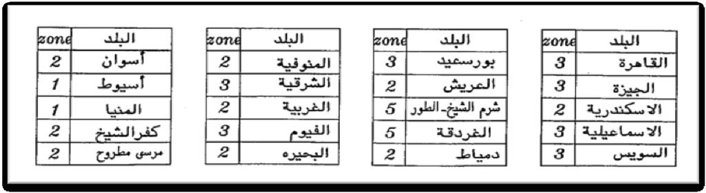
9 -2. Seismic Loads Equivalent static load According to the ECP1993 using Equivalent static load- see attached calculation in next calculation -Y-Y Direction -X-X Direction -Overturning Moment
10 Y-Y Direction Base Shear Basic Equiation: Equivalent Static Seismic Loads V = Z. I. K. C. S. W where: Z = Seismic Intensity Factor 0.1 first zone 0.2 second zone Enter value of Z third zone I = Building Importance Factor 1.25 Emergancy buildings: Hospitals, fire stations, Police stations, emergancy centers, communication building Enter value of I 1 1 Other buildings: Residential, commercial, public K = Structural System Coefficient 1.33 depends on lateral load resisting system and its ductility Box using shear walls or braced frames Frames only: 0.67 ductile frames 0.80 non-ductile frames Enter value of K Mixed system (shear walls and frames) where T: C = 1/ [15 sqrt( T )] C < = 0.12 Enter "1" for case (a) or "2" for case (b) 2 Enter No. of floors Calculated "T" = Calculated "C" = Chosen "C" 11 T = 0.1 N Case (a): for building with frames able to carry all the lateral force; where N = number of floors Enter value of H 33 T = 0.09 H / sqrt(b) Case (b): for other systems Enter value of B H = Height of building above foundation level Calculated "T" = Calculated "C" = Chosen "C" B = width of building in the direction of Earthquake S = Soil Coefficient 1.00 Rock, very dense > 15m, mid-dense < 15m above better soil conditions 1.15 Mid-dense or dense > 15m, or loose soil above better soil conditions Enter value of S loose or weak soil > 15m W = Weight of the building Enter weight of each floor in the followig table = Permenant loads; for building with live loads less or equal 500 kg/m2 = Permenant loads + 1/2 LL; for buildings with storage loads > 500 kg/m2
11 Lateral Load Distribution: Entered and Calculated Coefficient: Floor No. Floor Load (W) Height (H) from foundation Wi x Hi Force on each floor Z I K C S W V = Additional force at roof level (Ft) = 0.07 T. V (max V ; = 0 if T <= 0.7) Chosen "T" = Caculated "Ft" = Caculated "0.25 V" = S Ft = 0.00 T < or = 0.7 Over turning moment in Y- Dir Floor No Force on each floor Height (H) from foundation over turning moment total
12 X-X Direction Base Shear Basic Equiation: Equivalent Static Seismic Loads V = Z. I. K. C. S. W where: Z = Seismic Intensity Factor 0.1 first zone 0.2 second zone Enter value of Z third zone I = Building Importance Factor 1.25 Emergancy buildings: Hospitals, fire stations, Police stations, emergancy centers, communication building Enter value of I 1 1 Other buildings: Residential, commercial, public K = Structural System Coefficient 1.33 depends on lateral load resisting system and its ductility Box using shear walls or braced frames Frames only: 0.67 ductile frames 0.80 non-ductile frames Enter value of K Mixed system (shear walls and frames) where T: C = 1/ [15 sqrt( T )] C < = 0.12 Enter "1" for case (a) or "2" for case (b) 2 Enter No. of floors Calculated "T" = Calculated "C" = Chosen "C" 11 T = 0.1 N Case (a): for building with frames able to carry all the lateral force; where N = number of floors Enter value of H 33 T = 0.09 H / sqrt(b) Case (b): for other systems Enter value of B 38.8 H = Height of building above foundation level Calculated "T" = Calculated "C" = Chosen "C" B = width of building in the direction of Earthquake S = Soil Coefficient 1.00 Rock, very dense > 15m, mid-dense < 15m above better soil conditions 1.15 Mid-dense or dense > 15m, or loose soil above better soil conditions Enter value of S loose or weak soil > 15m W = Weight of the building Graduation Enter weight Project of each floor in the followig table = Permenant loads; for building with live loads less or equal 500 kg/m2 = Permenant loads + 1/2 Eng. LL; Magdy for buildings Mahmoud with storage loads > 500 kg/m2
13 Lateral Load Distribution: Entered and Calculated Coefficient: Floor No. Floor Load (W) Height (H) from foundation Wi x Hi Force on each floor Z I K C S W V = Additional force at roof level (Ft) = 0.07 T. V (max V ; = 0 if T <= 0.7) Chosen "T" = Caculated "Ft" = Caculated "0.25 V" = S Ft = 0.00 T < or = 0.7 Over turning moment in X- Dir Floor No Force on each floor Height (H) from foundation over turning moment total


14 Loads At X Direction At Y Direction
15 Response spectrum A- Response spectrum types B- Selected soil type Value of damping coefficient η = 1 Value of a g /g A g /g =0.125

16 C- Response modification factor R- (Reduction factor) R=5 E- Importance Factor Ordinary Residential Building I = 1 F- Modelling Requirements The mathematical model of the physical structure shall include all elements of the lateral force-resisting system. The model shall also include the stiffness and strength of elements, which are significant to the distribution of forces and shall represent the spatial distribution of the mass and stiffness of the structure. In addition, stiffness properties shall consider the effects of cracked sections. A reduction factor of Reduction factor of stiffness properties Beam Ieff/Ig 0.5 Column Ieff/Ig 0.7 Wall Ieff/Ig 0.7 Slabs Ieff/Ig 0.25 Calculated story drift shall not exceed 0.01 times the story height. Calculated Total drift at the final floor shall not exceed H/500, where H is the total Height of Building. G- Total Weight of Building Due to Ordinary Residential Building So W t = D.L L.L


17 The Egyptian code of loads ( )

18
19 Input Data SOIL TYPE A,B,C or D = c ZONE 1,2,3,4,5A or 5B = 2 REDUCTION FACTOR (R) = 5 Total Weight of building (TON)= 9319 TOTAL HEIGHT of building (m)= 32.8 IMPORTANCE FACTOR 1 or 1.2 = 1 T1= SR RESPONSE SPECTRUM CURVE hi Wi (ton) hi wi Fi (ton) Base Monet Summations
20 1.8. LOAD COMBINATIONS Combinations for Lateral Loads Case (1) Case (2) Case (3) P= (1.4 DL+1.6LL) P= 0.8(1.4 DL+1.6 LL+ lateral) P= (0.9DL +1.3 Lateral) E1 = 1.12 D.L. & 1.28 L.L & 0.8 EQx1 E2 = 1.12 D.L. & 1.28 L.L & -0.8 EQx1 E3 = 1.12 D.L. & 1.28 L.L & 0.8 EQx2 E4 = 1.12 D.L. & 1.28 L.L & -0.8 EQx2 E5 = 1.12 D.L. & 1.28 L.L & 0.8 EQY1 E6 = 1.12 D.L. & 1.28 L.L & -0.8 EQY1 E7 = 1.12 D.L. & 1.28 L.L & 0.8 EQY2 E8 = 1.12 D.L. & 1.28 L.L & -0.8 EQY2 E9 = 0.9 D.L. & 1.3 EQX1 E10 = 0.9 D.L. & -1.3 EQX1 E11 = 0.9 D.L. & 1.3 EQX2 E12 = 0.9 D.L. & -1.3 EQX2 E13 = 0.9 D.L. & 1.3 EQY1 E14 = 0.9 D.L. & -1.3 EQY1 E15 = 0.9 D.L. & 1.3 EQY2 E16 = 0.9 D.L. & EQY2 Because of wind is not affected in Egypt We designed under seismic loads only
21 3.3D FINITE ELEMENT MODEL
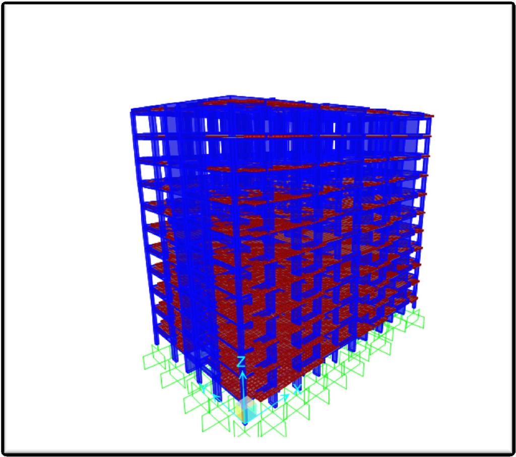
22
23 Max drift in X Direction= m Max drift in Y Direction= m Allowable Drift D=H/500 =32.8/500 = m Hense, Drift due to Seismic is less than allowabe Safe Drift.
24 4. DESIGN OF VERTICAL ELEMENTS DESIGN OF COLUMNS DESIGN OF SHEAR WALLS
25 4.1 DESIGN OF COLUMNS C1 (30x50) cm Material Properties: F cu = kg/cm2 E c = kg/cm2 F y = kg/cm2 E s = kg/cm2 Bracing System: Braced in both X and Y directions Geometry: Rectangular column Column Type: Short Column Reinforcement: Confinement: Tied Cover = mm Steel Area: 8 φ 16 Steel Ratio =.77% Min Steel Ratio = 0.60% Max Steel Ratio = 4.00% Stirrups: 2 φ 8 Stirrups Spacing = cm
26 C2 (30x70) cm Material Properties: F cu = kg/cm2 E c = kg/cm2 F y = kg/cm2 E s = kg/cm2 Bracing System: Braced in both X and Y directions Geometry: Rectangular column Column Type: Short Column Reinforcement: Confinement: Tied Cover = mm Steel Area: 12 φ 16 Steel Ratio = 1.15 % Min Steel Ratio = 0.60% Max Steel Ratio = 4.00% Stirrups:3 φ 8 Stirrups Spacing = cm
27 C3 (30x100) cm Material Properties: F cu = kg/cm2 E c = kg/cm2 F y = kg/cm2 E s = kg/cm2 Bracing System: Braced in both X and Y directions Geometry: Rectangular column Column Type: Short Column Reinforcement: Confinement: Tied Cover = mm Steel Area: 14 φ 16 Steel Ratio = 0.94 % Min Steel Ratio = 0.60% Max Steel Ratio = 4.00% Stirrups: 3 φ 8 Stirrups Spacing = cm
28 C4 (30x120) cm Material Properties: F cu = kg/cm2 E c = kg/cm2 F y = kg/cm2 E s = kg/cm2 Bracing System: Braced in both X and Y directions Geometry: Rectangular column Column Type: Short Column Reinforcement: Confinement: Tied Cover = mm Steel Area: 18 φ 16 Steel Ratio =1.01% Min Steel Ratio = 0.60% Max Steel Ratio = 4.00% Stirrups: 3 φ 8 Stirrups Spacing = cm
29 C5 (30x130) cm Material Properties: F cu = kg/cm2 E c = kg/cm2 F y = kg/cm2 E s = kg/cm2 Bracing System: Braced in both X and Y directions Geometry: Rectangular column Column Type: Short Column Reinforcement: Confinement: Tied Cover = mm Steel Area: 20 φ 16 Steel Ratio =1.03% Min Steel Ratio = 0.60% Max Steel Ratio = 4.00% Stirrups: 3 φ 8 Stirrups Spacing = cm
30 C6 (30x150) cm Material Properties: F cu = kg/cm2 E c = kg/cm2 F y = kg/cm2 E s = kg/cm2 Bracing System: Braced in both X and Y directions Geometry: Rectangular column Column Type: Short Column Reinforcement: Confinement: Tied Cover = mm Steel Area: 22 φ 16 Steel Ratio =0.98% Min Steel Ratio = 0.60% Max Steel Ratio = 4.00% Stirrups: 2 φ 8 Stirrups Spacing = cm
31 C7 (40x150) cm Material Properties: F cu = kg/cm2 E c = kg/cm2 F y = kg/cm2 E s = kg/cm2 Bracing System: Braced in both X and Y directions Geometry: Rectangular column Column Type: Short Column Reinforcement: Confinement: Tied Cover = mm Steel Area: 24 φ 16 Steel Ratio =0.80% Min Steel Ratio = 0.60% Max Steel Ratio = 4.00% Stirrups: 2 φ 8 Stirrups Spacing = cm
 cm Basic Design Parameters Caption = SW1 Default Concrete Strength, Fc = 250 kg/cm^2 Default Concrete Modulus, Ec = 240000 kg/cm^2 Maximum Concrete")
32 m 6 12 m DESIGN OF SHEAR WALLS AND CORE SW1 (30x308) cm Basic Design Parameters Caption = SW1 Default Concrete Strength, Fc = 250 kg/cm^2 Default Concrete Modulus, Ec = kg/cm^2 Maximum Concrete Strain = in/in Rebar Set = User Default Rebar Yeild Strength, Fy = 3600 kg/cm^2 Default Rebar Modulus, Es = kg/cm^2 Default Cover to Rebars = 2.50 cm Maximum Steel Strain = Infinity Transverse Rebar Type = Ties Total Shapes in Section = 1 Consider Slenderness = No Cross-section Shapes Shape Width Height Conc Fc S/S Curve cm cm kg/cm^2 Rectangular Shape PCA Parabola Rebar Properties Basic Section Properties: Total Width = cm Total Height = cm Center, Xo = 0.00 cm Center, Yo = 0.00 cm X-bar (Right) X-bar (Left) Y-bar (Top) Y-bar (Bot) Transformed Properties: Base Material Area, A Inertia, I33 Inertia, I22 Inertia, I32 Radius, r3 Radius, r2 = cm = cm = cm = cm = fc' = 250 kg/cm^2 = 9,000.0 cm^2 = 6.75E+07 cm^4 = 6.75E+05 cm^4 = 0.00E+00 cm^4 = cm = 8.66 cm 3.08

33 m 6 12 m 8 12 SW2 (30x360) cm Basic Design Parameters Caption = SW2 Default Concrete Strength, Fc = 250 kg/cm^2 Default Concrete Modulus, Ec = kg/cm^2 Maximum Concrete Strain = in/in Rebar Set = user Default Rebar Yeild Strength, Fy = 3600 kg/cm^2 Default Rebar Modulus, Es = kg/cm^2 Default Cover to Rebars = 2.50 cm Maximum Steel Strain = Infinity Transverse Rebar Type = Ties Total Shapes in Section = 1 Consider Slenderness = No Cross-section Shapes Shape Width Height Conc Fc S/S Curve cm cm kg/cm^2 Rectangular Shape PCA Parabola Rebar Properties Basic Section Properties: Total Width = cm Total Height = cm Center, Xo = 0.00 cm Center, Yo = 0.00 cm X-bar (Right) X-bar (Left) Y-bar (Top) Y-bar (Bot) = cm = cm = cm = cm Transformed Properties: Base Material = fc' = 250 kg/cm^2 Area, A Inertia, I33 Inertia, I22 Inertia, I32 Radius, r3 Radius, r2 = 1.08E+04 cm^2 = 1.17E+08 cm^4 = 8.10E+05 cm^4 = 0.00E+00 cm^4 = cm = 8.66 cm 3.60

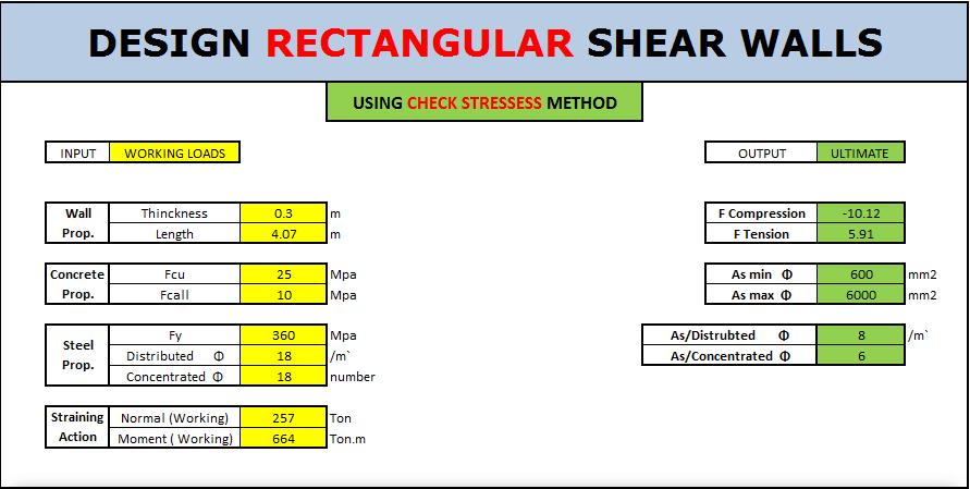
34 m 6 16 m 8 16 SW3 (30x407) cm Basic Design Parameters Caption = SW3 Default Concrete Strength, Fc = 250 kg/cm^2 Default Concrete Modulus, Ec = kg/cm^2 Maximum Concrete Strain = in/in Rebar Set = User Default Rebar Yeild Strength, Fy = 3600 kg/cm^2 Default Rebar Modulus, Es = kg/cm^2 Default Cover to Rebars = 2.50 cm Maximum Steel Strain = Infinity Transverse Rebar Type = Ties Total Shapes in Section = 1 Consider Slenderness = No Cross-section Shapes Shape Width Height Conc Fc S/S Curve cm cm kg/cm^2 Rectangular Shape PCA Parabola Rebar Properties Basic Section Properties Total Width = cm Total Height = cm Center, Xo = 0.00 cm Center, Yo = 0.00 cm X-bar (Right) X-bar (Left) Y-bar (Top) Y-bar (Bot) Transformed Properties: Base Material = fc' Area, A Inertia, I33 Inertia, I22 Inertia, I32 Radius, r3 Radius, r2 = cm = cm = cm = cm = 250 kg/cm^2 = 1.22E+04 cm^2 = 1.69E+08 cm^4 = 9.16E+05 cm^4 = 0.00E+00 cm^4 = cm = 8.66 cm 4.07

35 m 6 12 m 4 12 SW4 (30x252) cm Basic Design Parameters Caption = SW4 Default Concrete Strength, Fc = 250 kg/cm^2 Default Concrete Modulus, Ec = kg/cm^2 Maximum Concrete Strain = in/in Rebar Set = User Default Rebar Yeild Strength, Fy = 3600 kg/cm^2 Default Rebar Modulus, Es = kg/cm^2 Default Cover to Rebars = 2.50 cm Maximum Steel Strain = Infinity Transverse Rebar Type = Ties Total Shapes in Section = 1 Consider Slenderness = No Cross-section Shapes Shape Width Height Conc Fc S/S Curve cm cm kg/cm^2 Rectangular Shape PCA Parabola Basic Section Properties: Total Width Total Height Center, Xo Center, Yo X-bar (Right) X-bar (Left) Y-bar (Top) Y-bar (Bot) Transformed Properties: Base Material = fc' Area, A Inertia, I33 Inertia, I22 Inertia, I32 Radius, r3 Radius, r2 = cm = cm = 0.00 cm = 0.00 cm = cm = cm = cm = cm = 250 kg/cm^2 = 7,560.0 cm^2 = 4.00E+07 cm^4 = 5.67E+05 cm^4 = 0.00E+00 cm^4 = cm = 8.66 cm 2.52

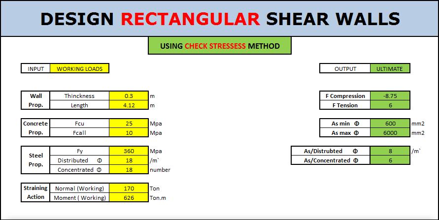
36 m 6 16 m 8 16 SW5 (30x412) cm Basic Design Parameters Caption = SW5 Default Concrete Strength, Fc = 250 kg/cm^2 Default Concrete Modulus, Ec = kg/cm^2 Maximum Concrete Strain = in/in Rebar Set = User Default Rebar Yeild Strength, Fy = 3600 kg/cm^2 Default Rebar Modulus, Es = kg/cm^2 Default Cover to Rebars = 2.50 cm Maximum Steel Strain = Infinity Transverse Rebar Type = Ties Total Shapes in Section = 1 Consider Slenderness = No Cross-section Shapes Shape Width Height Conc Fc S/S Curve cm cm kg/cm^2 Rectangular Shape PCA Parabola Basic Section Properties: Total Width Total Height Center, Xo Center, Yo X-bar (Right) X-bar (Left) Y-bar (Top) Y-bar (Bot) Transformed Properties: Base Material = fc' Area, A Inertia, I33 Inertia, I22 Inertia, I32 Radius, r3 Radius, r2 = cm = cm = 0.00 cm = 0.00 cm = cm = cm = cm = cm = 250 kg/cm^2 = 1.24E+04 cm^2 = 1.75E+08 cm^4 = 9.27E+05 cm^4 = 0.00E+00 cm^4 = cm = 8.66 cm 4.12
37 CORE Basic Design Parameters Caption = core Default Concrete Strength, Fc = 250 kg/cm^2 Default Concrete Modulus, Ec = kg/cm^2 Maximum Concrete Strain = in/in Rebar Set = User Default Rebar Yeild Strength, Fy = 3600 kg/cm^2 Default Rebar Modulus, Es = kg/cm^2 Default Cover to Rebars = 2.50 cm Maximum Steel Strain = Infinity Transverse Rebar Type = Ties Total Shapes in Section = 1 Consider Slenderness = No Cross-section Shapes Shape Width Height Conc Fc S/S Curve cm cm kg/cm^2 Rectangular Shape PCA Parabola Basic Section Properties: Total Width Total Height Center, Xo Center, Yo X-bar (Right) X-bar (Left) Y-bar (Top) Y-bar (Bot) Transformed Properties: Base Material = fc' Area, A Inertia, I33 Inertia, I22 Inertia, I32 Radius, r3 Radius, r2 = cm = cm = cm = cm = cm = cm = cm = cm = 250 kg/cm^2 = 1.62E+04 cm^2 = 5.55E+07 cm^4 = 2.44E+08 cm^4 = 0.00E+00 cm^4 = cm = cm m 6 18 m 6 12 m 6 12 m

38 SW1 SW2

39 SW3 SW4

40 SW5
41 5. DESIGN OF HORIZONTAL ELEMENTS DESIGN OF SLABS DESIGN OF STAIRS DESIGN OF BEAMS
42 5-1-1.Solid Slab (Typical Floors) Thickness of two way slabs =L/35 Simply supported =L/40 Continuous from one side =L/45 Continuous from two sides Take T=12cm for all slabs Check Deflection Allowable deflection = L/250 =3.32/250 =0.013m So actual deflection is < allowable Safe deflection
 b (mm) t (mm) d (mm) C1 J As (mm^2) As min As choose Rft. safty 1 3.7 1000 120 100 8.220 0.825 124.")
 6ø10 /m`")
43 Design of Section Fcu= 25 N/mm^2 Fy= 360 N/mm^2 cover = 20 mm slabs Mu (Kn.m/m') b (mm) t (mm) d (mm) C1 J As (mm^2) As min As choose Rft. safty f 10 safe f 10 safe f 10 safe f 10 safe Use lower mesh in both directions (11, 22) 6ø10 /m`
 Thickness of slab without drop panel =L/32 External panel =L/36 Internal panel Take T=18cm for all")
44 5-2-2.Flat Slab (First Floor) Thickness of slab without drop panel =L/32 External panel =L/36 Internal panel Take T=18cm for all slabs Check Deflection Allowable deflection = L/360 =3.32/360 =0.0092m So actual deflection is.0012 < allowable Safe deflection
45 Design of Section Check Punching Column 1
46 a=c+d/2 = /2=0.38 m b= c+d =1+0.16=1.16 m A net =2* *1.16= 6.83 m2 b0 =1.16+2*0.38=1.92 m Q=Wu *A net =( 0.18* )*6.83= ton qb = Q*103 / b o * d = 5.464*104 / 1920 *160 =0.178 MPa =1.29 MPa qall 0.8(α*d/b ) =1.1 MPa 0.316(a/b +0.5) =2.2 Mpa 1.6 MPa q all = 1.1 MPa q p Safe Punching
47 Column 2
48 a=c+d/2 = =0.46 m b= c+d = =0.86 m A net =2.52*4-0.46*0.86= 9.68 m2 b0 =2*0.86+2*0.46=2.64 m Q=Wu *A net =( 0.18* )*9.68= ton qb = Q*103 / b o * d = 7.744*104 / 2640 *160 =0.183 kg/cm2 =1.29 MPa qall 0.8(α*d/b ) =1.44 MPa 0.316(a/b +0.5) =3.05 Mpa 1.6 MPa q all = 1.1 MPa q p Safe Punching
49 5-1-2.Flat Slab (Ground Floor) Thickness of slab without drop panel =L/32 External panel =L/36 Internal panel Take T=18cm for all slabs Check Deflection Allowable deflection = L/360 =3.32/360 =0.0092m So actual deflection is.0021 < allowable Safe deflection

50 5-2. DESIGN OF STAIRS Using SAP2000 V16
 W u h =1.5(.2*2.5+.2+.3) =1.")
51 MANUAL DESIGN Statically system Concrete dimension L`= = =3.05m T S= for steel 400/600 T S= =13cm Take T S = 15cm Loads Wu=1.5(ts Ɣc +F.c + L.L) W u h =1.5(.2* ) =1.50 t/m 2 W u in =1.5((.2*2.5)/(cos29.4)+.2+.3)=1.61 t/m
52 Straining action Max Moment=6.40 ton.m Design D=ts-cover =20-2=18cm D=C 1 18=C 1 / C 1 =3.9 J=.8 As = cm 2 /m` Use 7Ф16/m`

53 Using Eng M.Zaghlal Program
54 DESIGN OF BEAMS Sec Beam (B1) Input data M U 4.4 t.m f y 3600 Kg/cm 2 Q U 5 t f cu 250 Kg/cm 2 b 12 cm E s 2E+06 Kg/cm 2 t 70 cm d 65 cm * Design of Beams concrete Fcu = 250 kg/cm 2 Steel F y = 3600 kg/cm 2 Sec. Ult. Moment Mu (m.t) Breadth b (cm) Depth t (cm) C1 J As (cm) ɸ Rft. Notes ɸ 12 safe m * Check Of shear in beams Concrete F cu = 300 kg/cm 2 Concrete q all = kg/cm 2 Stirrups F y = 2400 kg/cm Sec. Ult. Shear Breadth Depth q u b (cm) t (cm) Q u (ton) (kg/cm 2 ) As (cm) NO. of Branch ɸ Stirrups Notes ɸ 8 safe
55 0.70 Sec Beam (B2) Input data M U 8.8 t.m f y 3600 Kg/cm 2 Q U 9 t f cu 250 Kg/cm 2 b 12 cm E s 2E+06 Kg/cm 2 t 70 cm d 65 cm * Design of Beams concrete Fcu = 250 kg/cm 2 Steel F y = 3600 kg/cm 2 Sec. Ult. Moment Mu (m.t) Breadth b (cm) Depth t (cm) C1 J As (cm) ɸ Rft. Notes ɸ 12 safe m * Check Of shear in beams Concrete F cu = 250 kg/cm 2 Concrete q all = kg/cm 2 Stirrups F y = 2400 kg/cm Sec. Ult. Shear Breadth Depth q u b (cm) t (cm) Q u (ton) (kg/cm 2 ) As (cm) NO. of Branch ɸ Stirrups Notes ɸ 8 safe
56 0.70 Sec Beam (B3) Input data M U 13 t.m f y 3600 Kg/cm 2 Q U 9 t f cu 250 Kg/cm 2 b 12 cm E s 2E+06 Kg/cm 2 t 70 cm d 65 cm * Design of Beams concrete Fcu = 250 kg/cm 2 Steel F y = 3600 kg/cm 2 Sec. Ult. Moment Mu (m.t) Breadth b (cm) Depth t (cm) C1 J As (cm) ɸ Rft. Notes 2 ɸ 16 2 ɸ 12 safe ( With the same way shear in beam safe at 6 ɸ 8 / m \ ) m
57 0.70 Sec Beam (B4) Input data M U 15 t.m f y 3600 Kg/cm 2 Q U 10 t f cu 250 Kg/cm 2 b 12 cm E s 2E+06 Kg/cm 2 t 70 cm d 65 cm * Design of Beams concrete Fcu = 250 kg/cm 2 Steel F y = 3600 kg/cm 2 Sec. Ult. Moment Mu (m.t) Breadth b (cm) Depth t (cm) C1 J As (cm) ɸ Rft. Notes ɸ 16 safe (With the same way shear in beam safe at 6 ɸ 8 / m \ ) m
58 0.70 Sec Beam (B5) Input data M U 18 t.m f y 3600 Kg/cm 2 Q U 13.8 t f cu 250 Kg/cm 2 b 25 cm E s 2E+06 Kg/cm 2 t 70 cm d 65 cm * Design of Beams concrete Fcu = 250 kg/cm 2 Steel F y = 3600 kg/cm 2 Sec. Ult. Moment Mu (m.t) Breadth b (cm) Depth t (cm) C1 J As (cm) ɸ Rft. Notes ɸ 16 safe m * Check Of shear in beams Concrete F cu = 250 kg/cm 2 Concrete q all = kg/cm 2 Stirrups F y = 2400 kg/cm Sec. Ult. Shear Breadth Depth q u b (cm) t (cm) Q u (ton) (kg/cm 2 ) As (cm) NO. of Branch ɸ Stirrups Notes ɸ 8 safe
59 FINAL DESIGN OF BEAMS * Design of Beams concrete Fcu = 250 kg/cm 2 Steel F y = 3600 kg/cm 2 Sec. Ult. Moment Mu (m.t) Breadth b (cm) Depth t (cm) C1 J As (cm) ɸ R.F.T Notes ɸ 12 safe ɸ 12 safe ɸ 16 2 ɸ 12 safe ɸ 16 safe ɸ 16 safe Sec. * Check Of shear in beams Concrete F cu = 250 kg/cm 2 Concrete q all = kg/cm 2 Stirrups F y = 2400 kg/cm 2 Ult. Shear Breadth Depth q u b (cm) t (cm) Q u (ton) (kg/cm 2 ) As (cm) NO. of Branch ɸ Stirrups Notes ɸ 8 safe ɸ 8 safe ɸ 8 safe ɸ 8 safe ɸ 8 safe
60 DESIGN OF FOUNDATION DESIGN OF RAFT DESIGN OF PILE CAP
61 6-1.SHALLOW FOUNDATION (RAFT) Thickness of Raft Mx=72.25 ton.m D= D= =80.64 cm Take D=110 cm Check Stress under raft due to axial loads only -Get eccentricity Normal= t M x = t.m M y = t.m Y`= M x /N = 11.2 m X`= M y /N =19.28 m e x = = 0.2 m e y = = 0.13 m In order to eliminate eccentricity in Y Direction We took 30cm projection of raft in street in Y Direction so M x = zero -Get Additional moments due to eccentricity M Y = N*e y = *0.2= t.m Drawing showing that
62 11.07 Center of Mass and Center of Area Y X X Y
63 Get Properties of Section Area =821 m2 Iy = m4 0.5 ton / m X =±18.84 m Allowable stress q all = q allnet + ɣs *D F - ɣ p.c * t p.c - ɣ R.c * t R.c L.L = * *.3-2.5* = t/m2 -Actual stress F max = - * x = - - = t/m2 < t/m2 Less than allowable (safe) F min = - + * x = - + = t/m2 < zero No tension stress (safe)
64 6-2.Deep FOUNDATION (Pile Cap) Pile cap Manual Calculations
Design of Reinforced Concrete Structures (II)
") Design of Reinforced Concrete Structures (II) Discussion Eng. Mohammed R. Kuheil Review The thickness of one-way ribbed slabs After finding the value of total load (Dead and live loads), the elements are
Design of Reinforced Concrete Structures (II) Discussion Eng. Mohammed R. Kuheil Review The thickness of one-way ribbed slabs After finding the value of total load (Dead and live loads), the elements are
ε t increases from the compressioncontrolled Figure 9.15: Adjusted interaction diagram
 CHAPTER NINE COLUMNS 4 b. The modified axial strength in compression is reduced to account for accidental eccentricity. The magnitude of axial force evaluated in step (a) is multiplied by 0.80 in case
Sabah Shawkat Cabinet of Structural Engineering Walls carrying vertical loads should be designed as columns. Basically walls are designed in
 Sabah Shawkat Cabinet of Structural Engineering 17 3.6 Shear walls Walls carrying vertical loads should be designed as columns. Basically walls are designed in the same manner as columns, but there are
Annex - R C Design Formulae and Data
 The design formulae and data provided in this Annex are for education, training and assessment purposes only. They are based on the Hong Kong Code of Practice for Structural Use of Concrete 2013 (HKCP-2013).
4.3 Moment Magnification
 CHAPTER 4: Reinforced Concrete Columns 4.3 Moment Magnification Description An ordinary or first order frame analysis does not include either the effects of the lateral sidesway deflections of the column
A q u a b l u e a t t h e G o l d e n M i l e
 A q u a b l u e a t t h e G o l d e n M i l e H a t o R e y, P u e r t o R i c o G e n e r a l B u i l d i n g I n f o r m a t i o n Building Facts: 7-story parking structure + luxury apartments 900,000
Chapter (6) Geometric Design of Shallow Foundations
 Geometric Design of Shallow Foundations") Chapter (6) Geometric Design of Shallow Foundations Introduction As we stated in Chapter 3, foundations are considered to be shallow if if [D (3 4)B]. Shallow foundations have several advantages: minimum
Chapter (6) Geometric Design of Shallow Foundations Introduction As we stated in Chapter 3, foundations are considered to be shallow if if [D (3 4)B]. Shallow foundations have several advantages: minimum
Design of a Multi-Storied RC Building
 Design of a Multi-Storied RC Building 16 14 14 3 C 1 B 1 C 2 B 2 C 3 B 3 C 4 13 B 15 (S 1 ) B 16 (S 2 ) B 17 (S 3 ) B 18 7 B 4 B 5 B 6 B 7 C 5 C 6 C 7 C 8 C 9 7 B 20 B 22 14 B 19 (S 4 ) C 10 C 11 B 23
CHAPTER 4. Design of R C Beams
 CHAPTER 4 Design of R C Beams Learning Objectives Identify the data, formulae and procedures for design of R C beams Design simply-supported and continuous R C beams by integrating the following processes
Lecture-09 Introduction to Earthquake Resistant Analysis & Design of RC Structures (Part I)
") Lecture-09 Introduction to Earthquake Resistant Analysis & Design of RC Structures (Part I) By: Prof Dr. Qaisar Ali Civil Engineering Department UET Peshawar www.drqaisarali.com 1 Topics Introduction Earthquake
Lecture-09 Introduction to Earthquake Resistant Analysis & Design of RC Structures (Part I) By: Prof Dr. Qaisar Ali Civil Engineering Department UET Peshawar www.drqaisarali.com 1 Topics Introduction Earthquake
Rigid and Braced Frames
 RH 331 Note Set 12.1 F2014abn Rigid and raced Frames Notation: E = modulus of elasticit or Young s modulus F = force component in the direction F = force component in the direction FD = free bod diagram
Lecture-08 Gravity Load Analysis of RC Structures
 Lecture-08 Gravity Load Analysis of RC Structures By: Prof Dr. Qaisar Ali Civil Engineering Department UET Peshawar www.drqaisarali.com 1 Contents Analysis Approaches Point of Inflection Method Equivalent
Visit Abqconsultants.com. This program Designs and Optimises RCC Chimney and Foundation. Written and programmed
 Prepared by : Date : Verified by : Date : Project : Ref Calculation Output Design of RCC Chimney :- 1) Dimensions of Chimney and Forces 200 Unit weight of Fire Brick Lining 19000 N/m3 100 Height of Fire
PROPOSED SATSANG HALL TECHNICAL REPORT
 PROPOSED SATSANG HALL - VERTICAL STRIP V1 1 ------------------------------------------------------------------------------ ADAPT CORPORATION STRUCTURAL CONCRETE SOFTWARE SYSTEM 1733 Woodside Road, Suite
Case Study in Reinforced Concrete adapted from Simplified Design of Concrete Structures, James Ambrose, 7 th ed.
 ARCH 631 Note Set 11 S017abn Case Study in Reinforced Concrete adapted from Simplified Design of Concrete Structures, James Ambrose, 7 th ed. Building description The building is a three-story office building
Entrance exam Master Course
 - 1 - Guidelines for completion of test: On each page, fill in your name and your application code Each question has four answers while only one answer is correct. o Marked correct answer means 4 points
Civil Engineering Design (1) Design of Reinforced Concrete Columns 2006/7
 Design of Reinforced Concrete Columns 2006/7") Civil Engineering Design (1) Design of Reinforced Concrete Columns 2006/7 Dr. Colin Caprani, Chartered Engineer 1 Contents 1. Introduction... 3 1.1 Background... 3 1.2 Failure Modes... 5 1.3 Design Aspects...
Civil Engineering Design (1) Design of Reinforced Concrete Columns 2006/7 Dr. Colin Caprani, Chartered Engineer 1 Contents 1. Introduction... 3 1.1 Background... 3 1.2 Failure Modes... 5 1.3 Design Aspects...
spslab v3.11. Licensed to: STRUCTUREPOINT, LLC. License ID: D2DE-2175C File: C:\Data\CSA A Kt Revised.slb
 X Z Y spslab v3.11. Licensed to: STRUCTUREPOINT, LLC. License ID: 00000-0000000-4-2D2DE-2175C File: C:\Data\CSA A23.3 - Kt Revised.slb Project: CSA A23.3 - Kt Torsional Stiffness Illustration Frame: Engineer:
QUESTION BANK SEMESTER: III SUBJECT NAME: MECHANICS OF SOLIDS
 QUESTION BANK SEMESTER: III SUBJECT NAME: MECHANICS OF SOLIDS UNIT 1- STRESS AND STRAIN PART A (2 Marks) 1. Define longitudinal strain and lateral strain. 2. State Hooke s law. 3. Define modular ratio,
CIVIL DEPARTMENT MECHANICS OF STRUCTURES- ASSIGNMENT NO 1. Brach: CE YEAR:
 MECHANICS OF STRUCTURES- ASSIGNMENT NO 1 SEMESTER: V 1) Find the least moment of Inertia about the centroidal axes X-X and Y-Y of an unequal angle section 125 mm 75 mm 10 mm as shown in figure 2) Determine
PUNCHING SHEAR CALCULATIONS 1 ACI 318; ADAPT-PT
 Structural Concrete Software System TN191_PT7_punching_shear_aci_4 011505 PUNCHING SHEAR CALCULATIONS 1 ACI 318; ADAPT-PT 1. OVERVIEW Punching shear calculation applies to column-supported slabs, classified
QUESTION BANK DEPARTMENT: CIVIL SEMESTER: III SUBJECT CODE: CE2201 SUBJECT NAME: MECHANICS OF SOLIDS UNIT 1- STRESS AND STRAIN PART A
 DEPARTMENT: CIVIL SUBJECT CODE: CE2201 QUESTION BANK SEMESTER: III SUBJECT NAME: MECHANICS OF SOLIDS UNIT 1- STRESS AND STRAIN PART A (2 Marks) 1. Define longitudinal strain and lateral strain. 2. State
CHAPTER 5. T a = 0.03 (180) 0.75 = 1.47 sec 5.12 Steel moment frame. h n = = 260 ft. T a = (260) 0.80 = 2.39 sec. Question No.
 0.75 = 1.47 sec 5.12 Steel moment frame. h n = = 260 ft. T a = (260) 0.80 = 2.39 sec. Question No.") CHAPTER 5 Question Brief Explanation No. 5.1 From Fig. IBC 1613.5(3) and (4) enlarged region 1 (ASCE 7 Fig. -3 and -4) S S = 1.5g, and S 1 = 0.6g. The g term is already factored in the equations, thus
CHAPTER 5 Question Brief Explanation No. 5.1 From Fig. IBC 1613.5(3) and (4) enlarged region 1 (ASCE 7 Fig. -3 and -4) S S = 1.5g, and S 1 = 0.6g. The g term is already factored in the equations, thus
Design of AAC wall panel according to EN 12602
 Design of wall panel according to EN 160 Example 3: Wall panel with wind load 1.1 Issue Design of a wall panel at an industrial building Materials with a compressive strength 3,5, density class 500, welded
Fayoum University. Dr.: Youssef Gomaa Youssef
 Fayoum University Faculty o Engineering Department o Civil Engineering CE 40: Part Shallow Foundation Design Lecture No. (6): Eccentric Footing Dr.: Yousse Gomaa Yousse Eccentric Footing Eccentric ooting:
This Technical Note describes how the program checks column capacity or designs reinforced concrete columns when the ACI code is selected.
 COMPUTERS AND STRUCTURES, INC., BERKELEY, CALIFORNIA DECEMBER 2001 CONCRETE FRAME DESIGN ACI-318-99 Technical Note This Technical Note describes how the program checks column capacity or designs reinforced
DESIGN AND DETAILING OF COUNTERFORT RETAINING WALL
 DESIGN AND DETAILING OF COUNTERFORT RETAINING WALL When the height of the retaining wall exceeds about 6 m, the thickness of the stem and heel slab works out to be sufficiently large and the design becomes
1. ARRANGEMENT. a. Frame A1-P3. L 1 = 20 m H = 5.23 m L 2 = 20 m H 1 = 8.29 m L 3 = 20 m H 2 = 8.29 m H 3 = 8.39 m. b. Frame P3-P6
 Page 3 Page 4 Substructure Design. ARRANGEMENT a. Frame A-P3 L = 20 m H = 5.23 m L 2 = 20 m H = 8.29 m L 3 = 20 m H 2 = 8.29 m H 3 = 8.39 m b. Frame P3-P6 L = 25 m H 3 = 8.39 m L 2 = 3 m H 4 = 8.5 m L
Generation of Biaxial Interaction Surfaces
 COPUTERS AND STRUCTURES, INC., BERKELEY, CALIFORNIA AUGUST 2002 CONCRETE FRAE DESIGN BS 8110-97 Technical Note This Technical Note describes how the program checks column capacity or designs reinforced
Figure 1: Representative strip. = = 3.70 m. min. per unit length of the selected strip: Own weight of slab = = 0.
 Example (8.1): Using the ACI Code approximate structural analysis, design for a warehouse, a continuous one-way solid slab supported on beams 4.0 m apart as shown in Figure 1. Assume that the beam webs
SERVICEABILITY LIMIT STATE DESIGN
 CHAPTER 11 SERVICEABILITY LIMIT STATE DESIGN Article 49. Cracking Limit State 49.1 General considerations In the case of verifications relating to Cracking Limit State, the effects of actions comprise
ENERGY DIAGRAM w/ HYSTERETIC
 ENERGY DIAGRAM ENERGY DIAGRAM w/ HYSTERETIC IMPLIED NONLINEAR BEHAVIOR STEEL STRESS STRAIN RELATIONSHIPS INELASTIC WORK DONE HYSTERETIC BEHAVIOR MOMENT ROTATION RELATIONSHIP IDEALIZED MOMENT ROTATION DUCTILITY
Seismic Pushover Analysis Using AASHTO Guide Specifications for LRFD Seismic Bridge Design
 Seismic Pushover Analysis Using AASHTO Guide Specifications for LRFD Seismic Bridge Design Elmer E. Marx, Alaska Department of Transportation and Public Facilities Michael Keever, California Department
twenty one concrete construction: shear & deflection ARCHITECTURAL STRUCTURES: FORM, BEHAVIOR, AND DESIGN DR. ANNE NICHOLS SUMMER 2014 lecture
 ARCHITECTURAL STRUCTURES: FORM, BEHAVIOR, AND DESIGN DR. ANNE NICHOLS SUMMER 2014 lecture twenty one concrete construction: Copyright Kirk Martini shear & deflection Concrete Shear 1 Shear in Concrete
Flexure: Behavior and Nominal Strength of Beam Sections
 4 5000 4000 (increased d ) (increased f (increased A s or f y ) c or b) Flexure: Behavior and Nominal Strength of Beam Sections Moment (kip-in.) 3000 2000 1000 0 0 (basic) (A s 0.5A s ) 0.0005 0.001 0.0015
Practical Design to Eurocode 2
 Practical Design to Eurocode 2 The webinar will start at 12.30 (Any questions beforehand? use Questions on the GoTo Control Panel) Course Outline Lecture Date Speaker Title 1 21 Sep Jenny Burridge Introduction,
Example 2.2 [Ribbed slab design]
![Example 2.2 [Ribbed slab design]](/thumbs/78/77625473.jpg "Example 2.2 [Ribbed slab design]") Example 2.2 [Ribbed slab design] A typical floor system of a lecture hall is to be designed as a ribbed slab. The joists which are spaced at 400mm are supported by girders. The overall depth of the slab
Example 2.2 [Ribbed slab design] A typical floor system of a lecture hall is to be designed as a ribbed slab. The joists which are spaced at 400mm are supported by girders. The overall depth of the slab
USER BULLETIN 3: DETERMINATION OF UNSUPPORTED LENGTH RATIO L/Db
 USER BULLETIN 3: DETERMINATION OF UNSUPPORTED LENGTH RATIO L/Db The unsupported length ratio (L/Db) is calculated by the automatic Sectional modeler spreadsheet using Dhakal and Maekawa [1]. This method
Mechanics of Structure
 S.Y. Diploma : Sem. III [CE/CS/CR/CV] Mechanics of Structure Time: Hrs.] Prelim Question Paper Solution [Marks : 70 Q.1(a) Attempt any SIX of the following. [1] Q.1(a) Define moment of Inertia. State MI
Slenderness Effects for Concrete Columns in Sway Frame - Moment Magnification Method (CSA A )
") Slenderness Effects for Concrete Columns in Sway Frame - Moment Magnification Method (CSA A23.3-94) Slender Concrete Column Design in Sway Frame Buildings Evaluate slenderness effect for columns in a
Slenderness Effects for Concrete Columns in Sway Frame - Moment Magnification Method (CSA A23.3-94) Slender Concrete Column Design in Sway Frame Buildings Evaluate slenderness effect for columns in a
FRAME ANALYSIS. Dr. Izni Syahrizal bin Ibrahim. Faculty of Civil Engineering Universiti Teknologi Malaysia
 FRAME ANALYSIS Dr. Izni Syahrizal bin Ibrahim Faculty of Civil Engineering Universiti Teknologi Malaysia Email: iznisyahrizal@utm.my Introduction 3D Frame: Beam, Column & Slab 2D Frame Analysis Building
Roadway Grade = m, amsl HWM = Roadway grade dictates elevation of superstructure and not minimum free board requirement.
 Example on Design of Slab Bridge Design Data and Specifications Chapter 5 SUPERSTRUCTURES Superstructure consists of 10m slab, 36m box girder and 10m T-girder all simply supported. Only the design of Slab
SRI CHANDRASEKHARENDRA SARASWATHI VISWA MAHAVIDHYALAYA
 SRI CHANDRASEKHARENDRA SARASWATHI VISWA MAHAVIDHYALAYA (Declared as Deemed-to-be University under Section 3 of the UGC Act, 1956, Vide notification No.F.9.9/92-U-3 dated 26 th May 1993 of the Govt. of
A Comparative Study on RC Frame Structure Considering Lead Rubber Bearing and Triple Friction Pendulum Bearing
 A Comparative Study on RC Frame Structure Considering Lead Rubber Bearing and Triple Friction Pendulum Bearing Dr. H.M.Somasekharaiah 1, Er. Dharmesh. N 2, Mohammed Ghouse 3 Professor, Department of Civil
SPECIFIC VERIFICATION Chapter 5
 As = 736624/(0.5*413.69) = 3562 mm 2 (ADAPT 3569 mm 2, B29, C6) Data Block 27 - Compressive Stresses The initial compressive strength, f ci, is the strength entered in the Material/Concrete input screen.
Job No. Sheet No. Rev. CONSULTING Engineering Calculation Sheet. Member Design - Reinforced Concrete Staircase BS8110
 CONSULTING Engineering Calculation Sheet E N G I N E E R S Consulting Engineers jxxx 1 Material Properties Characteristic strength of concrete, f cu ( 60N/mm 2 ; HSC N/A) 30 N/mm 2 OK Yield strength of
DESIGN REINFORCED CEMENT CONCRETE STRUCTURAL MEMBERS
 DESIGN OF REINFORCED CEMENT CONCRETE STRUCTURAL MEMBERS Contents CHAPTER 1.0 General: 1.1 Symbols 1. Materials 1..1 Cement 1.. Aggregate 1..3 Water 1..4 Admixtures 1..5 Reinforcement CHAPTER.0 Concrete:.1
Design of a Balanced-Cantilever Bridge
 Design of a Balanced-Cantilever Bridge CL (Bridge is symmetric about CL) 0.8 L 0.2 L 0.6 L 0.2 L 0.8 L L = 80 ft Bridge Span = 2.6 L = 2.6 80 = 208 Bridge Width = 30 No. of girders = 6, Width of each girder
Bending and Shear in Beams
 Bending and Shear in Beams Lecture 3 5 th October 017 Contents Lecture 3 What reinforcement is needed to resist M Ed? Bending/ Flexure Section analysis, singly and doubly reinforced Tension reinforcement,
REINFORCED CONCRETE STRUCTURES DESIGN AND DRAWING (ACE009)
") LECTURE NOTES ON REINFORCED CONCRETE STRUCTURES DESIGN AND DRAWING (ACE009) III B. Tech I semester (Regulation- R16) Mr. Gude Ramakrishna Associate Professor DEPARTMENT OF CIVIL ENGINEERING INSTITUTE OF
LECTURE NOTES ON REINFORCED CONCRETE STRUCTURES DESIGN AND DRAWING (ACE009) III B. Tech I semester (Regulation- R16) Mr. Gude Ramakrishna Associate Professor DEPARTMENT OF CIVIL ENGINEERING INSTITUTE OF
A Modified Response Spectrum Analysis Procedure (MRSA) to Determine the Nonlinear Seismic Demands of Tall Buildings
 to Determine the Nonlinear Seismic Demands of Tall Buildings") Fawad A. Najam Pennung Warnitchai Asian Institute of Technology (AIT), Thailand Email: fawad.ahmed.najam@ait.ac.th A Modified Response Spectrum Analysis Procedure (MRSA) to Determine the Nonlinear Seismic
Fawad A. Najam Pennung Warnitchai Asian Institute of Technology (AIT), Thailand Email: fawad.ahmed.najam@ait.ac.th A Modified Response Spectrum Analysis Procedure (MRSA) to Determine the Nonlinear Seismic
DESIGN OF STAIRCASE. Dr. Izni Syahrizal bin Ibrahim. Faculty of Civil Engineering Universiti Teknologi Malaysia
 DESIGN OF STAIRCASE Dr. Izni Syahrizal bin Ibrahim Faculty of Civil Engineering Universiti Teknologi Malaysia Email: iznisyahrizal@utm.my Introduction T N T G N G R h Flight Span, L Landing T = Thread
FLEXIBLE BUILDING BASEMENT WITH MULTICOLUMNS
 011 FLEXIBLE BUILDING BASEMENT WITH MULTICOLUMNS Luis CARRILLO-GUTIERR 1 SUMMARY This invention is a passive seismic isolation system, which taking advantage of the resilience and flexibility that characterise
PEER/SSC Tall Building Design. Case study #2
 PEER/SSC Tall Building Design Case study #2 Typical Plan View at Ground Floor and Below Typical Plan View at 2 nd Floor and Above Code Design Code Design Shear Wall properties Shear wall thickness and
Beam Design and Deflections
 Beam Design and Deflections tation: a = name for width dimension A = name for area Areq d-adj = area required at allowable stress when shear is adjusted to include self weight Aweb = area of the web of
CONSULTING Engineering Calculation Sheet. Job Title Member Design - Reinforced Concrete Column BS8110
 E N G I N E E R S Consulting Engineers jxxx 1 Job Title Member Design - Reinforced Concrete Column Effects From Structural Analysis Axial force, N (tension-ve and comp +ve) (ensure >= 0) 8000kN OK Major
REINFORCED CONCRETE DESIGN 1. Design of Column (Examples and Tutorials)
") For updated version, please click on http://ocw.ump.edu.my REINFORCED CONCRETE DESIGN 1 Design of Column (Examples and Tutorials) by Dr. Sharifah Maszura Syed Mohsin Faculty of Civil Engineering and Earth
For updated version, please click on http://ocw.ump.edu.my REINFORCED CONCRETE DESIGN 1 Design of Column (Examples and Tutorials) by Dr. Sharifah Maszura Syed Mohsin Faculty of Civil Engineering and Earth
EFFECT OF SHEAR REINFORCEMENT ON FAILURE MODE OF RC BRIDGE PIERS SUBJECTED TO STRONG EARTHQUAKE MOTIONS
 EFFECT OF SHEAR REINFORCEMENT ON FAILURE MODE OF RC BRIDGE PIERS SUBJECTED TO STRONG EARTHQUAKE MOTIONS Atsuhiko MACHIDA And Khairy H ABDELKAREEM SUMMARY Nonlinear D FEM was utilized to carry out inelastic
Associate Professor. Tel:
 DEPARTMENT OF CIVIL ENGINEERING IIT DELHI Dr. Suresh Bhalla Associate Professor Tel: 2659-1040 Email: Sbhalla@civil.iitd.ac.in FOUNDATIONS Geotechnical Engineer Structural Engineer Location and depth criteria
Job No. Sheet No. Rev. CONSULTING Engineering Calculation Sheet. Member Design - Steel Composite Beam XX 22/09/2016
 CONSULTING Engineering Calculation Sheet jxxx 1 Member Design - Steel Composite Beam XX Introduction Chd. 1 Grade 50 more common than Grade 43 because composite beam stiffness often 3 to 4 times non composite
UNIT-I STRESS, STRAIN. 1. A Member A B C D is subjected to loading as shown in fig determine the total elongation. Take E= 2 x10 5 N/mm 2
 UNIT-I STRESS, STRAIN 1. A Member A B C D is subjected to loading as shown in fig determine the total elongation. Take E= 2 x10 5 N/mm 2 Young s modulus E= 2 x10 5 N/mm 2 Area1=900mm 2 Area2=400mm 2 Area3=625mm
ME Final Exam. PROBLEM NO. 4 Part A (2 points max.) M (x) y. z (neutral axis) beam cross-sec+on. 20 kip ft. 0.2 ft. 10 ft. 0.1 ft.
 M (x) y. z (neutral axis) beam cross-sec+on. 20 kip ft. 0.2 ft. 10 ft. 0.1 ft.") ME 323 - Final Exam Name December 15, 2015 Instructor (circle) PROEM NO. 4 Part A (2 points max.) Krousgrill 11:30AM-12:20PM Ghosh 2:30-3:20PM Gonzalez 12:30-1:20PM Zhao 4:30-5:20PM M (x) y 20 kip ft 0.2
ME 323 - Final Exam Name December 15, 2015 Instructor (circle) PROEM NO. 4 Part A (2 points max.) Krousgrill 11:30AM-12:20PM Ghosh 2:30-3:20PM Gonzalez 12:30-1:20PM Zhao 4:30-5:20PM M (x) y 20 kip ft 0.2
DEFORMATION CAPACITY OF OLDER RC SHEAR WALLS: EXPERIMENTAL ASSESSMENT AND COMPARISON WITH EUROCODE 8 - PART 3 PROVISIONS
 DEFORMATION CAPACITY OF OLDER RC SHEAR WALLS: EXPERIMENTAL ASSESSMENT AND COMPARISON WITH EUROCODE 8 - PART 3 PROVISIONS Konstantinos CHRISTIDIS 1, Emmanouil VOUGIOUKAS 2 and Konstantinos TREZOS 3 ABSTRACT
Downloaded from Downloaded from / 1
 PURWANCHAL UNIVERSITY III SEMESTER FINAL EXAMINATION-2002 LEVEL : B. E. (Civil) SUBJECT: BEG256CI, Strength of Material Full Marks: 80 TIME: 03:00 hrs Pass marks: 32 Candidates are required to give their
Lecture-05 Serviceability Requirements & Development of Reinforcement
 Lecture-05 Serviceability Requirements & Development of Reinforcement By: Prof Dr. Qaisar Ali Civil Engineering Department UET Peshawar drqaisarali@uetpeshawar.edu.pk www.drqaisarali.com 1 Section 1: Deflections
Where and are the factored end moments of the column and >.
 11 LIMITATION OF THE SLENDERNESS RATIO----( ) 1-Nonsway (braced) frames: The ACI Code, Section 6.2.5 recommends the following limitations between short and long columns in braced (nonsway) frames: 1. The
Chapter 4 Seismic Design Requirements for Building Structures
 Chapter 4 Seismic Design Requirements for Building Structures where: F a = 1.0 for rock sites which may be assumed if there is 10 feet of soil between the rock surface and the bottom of spread footings
7.2 Design of minaret: Geometry:
 7. Design of minaret: Geometry: The figure below shows the longitudinal section in the minaret and the cross section will be shown when start calculate the self-weight of each section. Figure 7..1 Longitudinal
Design of Beams (Unit - 8)
") Design of Beams (Unit - 8) Contents Introduction Beam types Lateral stability of beams Factors affecting lateral stability Behaviour of simple and built - up beams in bending (Without vertical stiffeners)
Design of Beams (Unit - 8) Contents Introduction Beam types Lateral stability of beams Factors affecting lateral stability Behaviour of simple and built - up beams in bending (Without vertical stiffeners)
R13. II B. Tech I Semester Regular Examinations, Jan MECHANICS OF SOLIDS (Com. to ME, AME, AE, MTE) PART-A
 PART-A") SET - 1 II B. Tech I Semester Regular Examinations, Jan - 2015 MECHANICS OF SOLIDS (Com. to ME, AME, AE, MTE) Time: 3 hours Max. Marks: 70 Note: 1. Question Paper consists of two parts (Part-A and Part-B)
SET - 1 II B. Tech I Semester Regular Examinations, Jan - 2015 MECHANICS OF SOLIDS (Com. to ME, AME, AE, MTE) Time: 3 hours Max. Marks: 70 Note: 1. Question Paper consists of two parts (Part-A and Part-B)
SERVICEABILITY OF BEAMS AND ONE-WAY SLABS
 CHAPTER REINFORCED CONCRETE Reinforced Concrete Design A Fundamental Approach - Fifth Edition Fifth Edition SERVICEABILITY OF BEAMS AND ONE-WAY SLABS A. J. Clark School of Engineering Department of Civil
Accordingly, the nominal section strength [resistance] for initiation of yielding is calculated by using Equation C-C3.1.
![Accordingly, the nominal section strength [resistance] for initiation of yielding is calculated by using Equation C-C3.1.](/thumbs/89/98617066.jpg "Accordingly, the nominal section strength [resistance] for initiation of yielding is calculated by using Equation C-C3.1.") C3 Flexural Members C3.1 Bending The nominal flexural strength [moment resistance], Mn, shall be the smallest of the values calculated for the limit states of yielding, lateral-torsional buckling and distortional
C3 Flexural Members C3.1 Bending The nominal flexural strength [moment resistance], Mn, shall be the smallest of the values calculated for the limit states of yielding, lateral-torsional buckling and distortional
Chapter. Materials. 1.1 Notations Used in This Chapter
 Chapter 1 Materials 1.1 Notations Used in This Chapter A Area of concrete cross-section C s Constant depending on the type of curing C t Creep coefficient (C t = ε sp /ε i ) C u Ultimate creep coefficient
Assignment 1 - actions
 Assignment 1 - actions b = 1,5 m a = 1 q kn/m 2 Determine action on the beam for verification of the ultimate limit state. Axial distance of the beams is 1 to 2 m, cross section dimensions 0,45 0,20 m
Job No. Sheet No. Rev. CONSULTING Engineering Calculation Sheet. Member Design - Reinforced Concrete Staircase BS8110
 CONSULTING Engineering Calculation Sheet E N G I N E E R S Consulting Engineers jxxx 1 Material Properties Characteristic strength of concrete, f cu ( 60N/mm 2 ; HSC N/A) 25 N/mm 2 OK Yield strength of
ENG1001 Engineering Design 1
 ENG1001 Engineering Design 1 Structure & Loads Determine forces that act on structures causing it to deform, bend, and stretch Forces push/pull on objects Structures are loaded by: > Dead loads permanent
Engineering Science OUTCOME 1 - TUTORIAL 4 COLUMNS
 Unit 2: Unit code: QCF Level: Credit value: 15 Engineering Science L/601/10 OUTCOME 1 - TUTORIAL COLUMNS 1. Be able to determine the behavioural characteristics of elements of static engineering systems
OP-023. INTERPRETATION OF INSTRUMENTED TEST PILE RESULT
 INTERPRETATION OF INSTRUMENTED TEST PILE RESULT Page 1 of 9 WORK INSTRUCTIONS FOR ENGINEERS GSJ Compiled by : Checked by KYW : LSS Approved by : OP-23. INTERPRETATION OF INSTRUMENTED TEST PILE RESULT INTERPRETATION
Design of reinforced concrete sections according to EN and EN
 Design of reinforced concrete sections according to EN 1992-1-1 and EN 1992-2 Validation Examples Brno, 21.10.2010 IDEA RS s.r.o. South Moravian Innovation Centre, U Vodarny 2a, 616 00 BRNO tel.: +420-511
Design of Reinforced Concrete Beam for Shear
 Lecture 06 Design of Reinforced Concrete Beam for Shear By: Prof Dr. Qaisar Ali Civil Engineering Department UET Peshawar drqaisarali@uetpeshawar.edu.pk 1 Topics Addressed Shear Stresses in Rectangular
Earthquake Loads According to IBC IBC Safety Concept
 Earthquake Loads According to IBC 2003 The process of determining earthquake loads according to IBC 2003 Spectral Design Method can be broken down into the following basic steps: Determination of the maimum
Lecture-04 Design of RC Members for Shear and Torsion
 Lecture-04 Design of RC Members for Shear and Torsion By: Prof. Dr. Qaisar Ali Civil Engineering Department UET Peshawar drqaisarali@uetpeshawar.edu.pk www.drqaisarali.com 1 Topics Addressed Design of
A Mathematical Formulation to Estimate the Fundamental Period of High-Rise Buildings Including Flexural-Shear Behavior and Structural Interaction
 Journal of Solid Mechanics Vol. 6, No. (014) pp. 1-134 A Mathematical Formulation to Estimate the Fundamental Period of High-Rise Buildings Including Flexural-Shear Behavior and Structural Interaction
Prof. A. Meher Prasad. Department of Civil Engineering Indian Institute of Technology Madras
 Prof. A. Meher Prasad Department of Civil Engineering Indian Institute of Technology Madras email: prasadam@iitm.ac.in Dynamic - Loads change with time Nonlinear - Loaded beyond Elastic Limit Type Usual
Deep Foundations 2. Load Capacity of a Single Pile
 Deep Foundations 2 Load Capacity of a Single Pile All calculations of pile capacity are approximate because it is almost impossible to account for the variability of soil types and the differences in the
Chapter 7: Bending and Shear in Simple Beams
 Chapter 7: Bending and Shear in Simple Beams Introduction A beam is a long, slender structural member that resists loads that are generally applied transverse (perpendicular) to its longitudinal axis.
STRUCTURAL ANALYSIS CHAPTER 2. Introduction
 CHAPTER 2 STRUCTURAL ANALYSIS Introduction The primary purpose of structural analysis is to establish the distribution of internal forces and moments over the whole part of a structure and to identify
Special edition paper
 Development of New Aseismatic Structure Using Escalators Kazunori Sasaki* Atsushi Hayashi* Hajime Yoshida** Toru Masuda* Aseismatic reinforcement work is often carried out in parallel with improvement
Beam Design - Shed Roof Back Wall Beam-S
 Beam Design - Shed Roof Back Wall Beam-S 1. Beam Data Load Type: Uniform Dist. Load Support: Simple Beam Beam Type: Glulam Species: Western Species Grade: 24F-V4 1.8E DF/DF Size: 2.5 x 6 Design Span (L):
999 TOWN & COUNTRY ROAD ORANGE, CALIFORNIA TITLE PUSHOVER ANALYSIS EXAMPLE BY R. MATTHEWS DATE 5/21/01
 DESCRIPTION Nonlinear static (pushover) analysis will be performed on a railroad bridge bent using several methods to determine its ultimate lateral deflection capability. 1. SAP2000 Nonlinear with axial-moment
Serviceability Deflection calculation
 Chp-6:Lecture Goals Serviceability Deflection calculation Deflection example Structural Design Profession is concerned with: Limit States Philosophy: Strength Limit State (safety-fracture, fatigue, overturning
UNIT II SHALLOW FOUNDATION
 Introduction UNIT II SHALLOW FOUNDATION A foundation is a integral part of the structure which transfer the load of the superstructure to the soil. A foundation is that member which provides support for
An Investigation on the Correlation of Inter-story Drift and Performance Objectives in Conventional RC Frames
 Available online at www.ijournalse.org Emerging Science Journal Vol., No. 3, June, 18 An Investigation on the Correlation of Inter-story Drift and Performance Objectives in Conventional RC Frames Saeed
Suspended high-rise. Suspended high-rise Copyright G G Schierle, press Esc to end, for next, for previous slide 1
 Suspended high-rise Suspended high-rise Copyright G G Schierle, 2001-06 press Esc to end, for next, for previous slide 1 Suspended high-rise 1 Gravity load path 2 Differential deflection 3 Prestress to
Comparative Study of Strengths of Two-Way Rectangular Continuous Slabs with Two Openings Parallel to Long Side and Short Side
 Volume 6, No. 2, February 17 9 Comparative Study of Strengths of Two-Way Rectangular Continuous Slabs with Two Openings Parallel to Long Side and Short Side D. Manasa, Assistant Professor, Gayatri Vidya
PERIYAR CENTENARY POLYTECHNIC COLLEGE PERIYAR NAGAR - VALLAM THANJAVUR. DEPARTMENT OF MECHANICAL ENGINEERING QUESTION BANK
 PERIYAR CENTENARY POLYTECHNIC COLLEGE PERIYAR NAGAR - VALLAM - 613 403 - THANJAVUR. DEPARTMENT OF MECHANICAL ENGINEERING QUESTION BANK Sub : Strength of Materials Year / Sem: II / III Sub Code : MEB 310
IVIL.COM, C. English - Arabic. Arrow Assume Assumption Available Average Axes Axial Axis
 Abrupt Action Accuracy Accurate Advantage Algebra Algebraic Algebraic equation English - Arabic Algebraic expression Algebraic sum Allow Allowable Ambiguous Analyze Analysis f sections Structural analysis
APRIL Conquering the FE & PE exams Formulas, Examples & Applications. Topics covered in this month s column:
 APRIL 2015 DR. Z s CORNER Conquering the FE & PE exams Formulas, Examples & Applications Topics covered in this month s column: PE Exam Specifications (Geotechnical) Transportation (Horizontal Curves)
Only for Reference Page 1 of 18
 Only for Reference www.civilpddc2013.weebly.com Page 1 of 18 Seat No.: Enrolment No. GUJARAT TECHNOLOGICAL UNIVERSITY PDDC - SEMESTER II EXAMINATION WINTER 2013 Subject Code: X20603 Date: 26-12-2013 Subject
Earthquake Simulation Tests on a 1:5 Scale 10 - Story RC Residential Building Model
 Earthquake Simulation Tests on a 1:5 Scale 1 - Story RC Residential Building Model H. S. Lee, S. J. Hwang, K. B. Lee, & C. B. Kang Korea University, Seoul, Republic of Korea S. H. Lee & S. H. Oh Pusan