Pine Falls Generation Station Facility Up-grade Interconnection Facility Study
|
|
|
- Aubrie Shepherd
- 5 years ago
- Views:
Transcription
1 Pine Falls Generation Station Facility Up-grade Interconnection Facility Study Performed by: Manitoba Hydro System Planning Department Project Leader: Dave Jacobson, P.Eng, PhD Principal Contributors: Glenn Evans, CET Other Contributors: Gerry Lane Rae Yang, P.Eng Mike Wonsiak File: 7-2D Date: March 3, 2009
2 2
3 Executive Summary The objective of this study was to identify any possible system deficiencies and impacts attributed to a planned facility upgrade at Pine Falls Generation Station. For this study, two levels of generation increase were studied. The primary analysis was a proposed generation increase of 11.7 MW total (Pmax output from 89.6 MW to MW). The estimated output increase would be to units 1 & 2 at 5.85 MW each. An alternative generation increase involving units 1-4 was also looked at as a sensitivity. Total output was increased 19.8 MW from 89.6 MW to MW assuming an increase to units 1-4 of 4.95 MW each. The latest proposed in service date for units 1 & 2 is summer 2011 and for units 3 & 4 is summer At present there are two types of Interconnection Services available for Pine Falls GS. They are as follows; 1. Network Resource Interconnection Service (NRIS) Language within the Manitoba Hydro Open Access Interconnection Tariff (OAIT) states, NRIS allows the Generator s Facility to be designated as a Network Resource, up to the facility s full output, on the same basis as existing Network Resources interconnected to Manitoba Hydro s System. NRIS in and of itself does not convey any right to deliver electricity to any specific customer or Point of Delivery. In order to be classified as NRIS status: Interconnection Facilities, Interconnection System Upgrades and Network upgrades must be satisfied. The Manitoba Hydro Transmission System Interconnections Generation Queue has allotted 14 MW for study purposes and accreditation. With option 2 upgrades of 19.8 MW (Units 1-4), only 14 MW could be granted NRIS status. The additional 5.8 MW would have to be placed back into the generation queue for evaluation. 2. Energy Resource Interconnection Service (ERIS) Language within the Manitoba Hydro Open Access Interconnection Tariff (OAIT) states, ERIS allows the Generator to connect the facility to the system and be eligible to deliver the facility s output using existing firm or non-firm capacity of the Transmission System on an as available basis. ERIS does not in and of itself convey any right to deliver electricity to any specific customer or Point of Delivery. In order to be classified as ERIS status: Interconnection Facilities, Interconnection System Upgrades but not Network upgrades are satisfied. Again only 14 MW could be deemed as Energy Resource and the remainder would have to be placed back into the queue for evaluation. This study also investigated the impact of varied export levels and generation output from Selkirk with the proposed Pine Falls facility upgrades on the system. Generally speaking, conditions of Selkirk Generation in service with high Winnipeg River Generation and high exports to Ontario introduced overloads within the Winnipeg River Transmission system. Refer to the Pine Falls IES for more detail. Single Contingency Analysis, Stability Analysis and Short Circuit Analysis were investigated. Both stability analysis and short circuit analysis investigations demonstrated no impact due to the Pine Falls Facility upgrade. Single contingency analysis identified 3
4 major transmission line deficiencies. Minimum network facility upgrades incurred from the proposed Pine Falls upgrades are as follows. These minimum requirements are based on firm exports to Ontario (200 MW). It should be noted that irregardless of the upgrade option, the affected facilities remain the same. Costs for these upgrades are approximately $117 k, for option 1. Further enhancement costs of approximately $24 K would be required for combining options 1 & 2. There is a possibility of cost adjustment for the Transcona - WT 34 riser upgrades depending on time of the projects. The projects being; Pine Falls Units 1 & 2, Transcona New 230 kv - 66kV Station and Pine Falls Units 3 &4. The Transcona project has previously identified the deficiencies of the risers. Pine Falls Unit 1 & 2 upgrades would advance the replacement of the risers. Refer to appendix E for an estimate breakdown. A list of the affected equipment is as follows: Station Work Upgrade Ridgeway R23R Riser (pre-existing problem, not (N/A) required for IFS, see section 3.2) Transcona WT34 (Network Upgrade) Pine Falls - Hourly Unit Discharge (Inter-connection System Upgrade) Pine Falls - Breaker CT upgrade (Inter-connection System Upgrade) Pine Falls - Line Protection Issues (Inter-connection System Upgrades) Risers (during summer peak conditions) TSIR requirement 600 A CT s, in conjunction with breaker replacement project. 600 A CT s with new breakers Of significant notability was the investigation into a stuck breaker scenario, based on the existing protection system. Independently, Rae Yang of System Planning supplied comments from her study of a Single Line to Ground 99% down PC4. It was discovered that the SLG fault would not clear and adjusting adjacent GP1 and PR2 protection would not isolate the fault. Rae recommends breaker fail protection, negative sequence generator protection and replacement of the existing relay protection to newer micro processor protection. An excerpt from her comments is as follows: "At the moment, Pine Falls generators do not have negative sequence current protection and the criteria for negative sequence current at the generator after the fault is not exceeding 10% of the nominal current of the machine. If the single line to ground fault cannot be cleared, the unbalanced fault causes a negative sequence current component in the stator current. This current leads to a counter-rotating flux field in the machine and causes double frequency currents to flow in the rotor iron and slot wedges, resulting in local heating the generators could be damaged if the fault is not cleared." 4
5 It is my general understanding that Generation Maintenance Engineering has a number of projects planned for Pine Falls including breaker replacements, low voltage breaker additions, generation controls and protection systems. In light of this, information was sent to Generation for support in reference to the protection systems upgrades. Therefore, deficiencies found from the stuck breaker study are required to be rectified in conjunction with this project. Further to the breaker replacement, Pine Falls will be required to have all existing 14 HV breakers replaced by These breakers have been mechanically failing and contain PCB s within the bushings. A sensitivity study was performed to explore alternate breaker numbers and some site modifications. That was; high side breaker reduction from 14 to 11 and co-termination of generators units 1-2, units 3-4 and units 5-6. Operationally and system stability wise either one-for-one high-side breaker replacement or breaker reduction and generation co-termination creates no issues. With the increase in generation capacity, there are some concerns pertaining to current flow within the ring. The switchyard arrangement at Pine Falls is of two ring busses tied together through one section. The existing CT ratings of the breakers are 300 A. In both schemes, whenever one breaker was simulated out of service the rating of all the remaining breakers CT s were exceeded. The bus rating was not violated. It is recommended that the replacement breakers have CT s rated at 600 A. This could have an impact on the line protection relay scheme and new relay equipment maybe required. 5
6 Table of Contents 1.0 Introduction Objectives ACCC analysis Stability analysis Fault analysis Study Criteria Operating Criteria Generator Interconnection Requirements Base Case Study Models for steady state analysis ACCC Analysis Single Contingency ACCC Analysis Single Contingency (Multiple Elements) ACCC Analysis Conclusions Stability Analysis Stability Disturbance Analysis Results Fault p1z observations Fault p2z observations Fault p3z observations Fault p4z observations Fault p6s observations Faults p7s and p8s observations Fault p9s observations Stability Disturbance Analysis Conclusions Short Circuit Analysis Breaker Replacement Sensitivity Breaker Replacement Sensitivity - Load Flow Breaker Replacement Sensitivity - Stability Conclusions 23 Appendices Appendix A Appendix B Appendix C Appendix D Appendix E Appendix F Appendix G Appendix H Appendix I Appendix J Appendix K Appendix L LF/ACCC File Names ACCC Screening Summary, Summer Off-Peak ACCC Screening Summary, Summer Peak ACCC Screening Summary, Winter Peak Facility Up-grades Estimated Dollars and WT34 SLD Summer Off-Peak, Stability and Power Flow (Faults p1z, p2z, p3z, p4z, p6s, p7s, and p8s) Winnipeg River Accredited Generation Outputs Pine Falls Proposed Generation Upgrades Relay Report, Stuck Breaker Study Pine Falls Up-grades, Fault Levels on Local Circuit Breakers Generator Interconnection Requirements, Table A1 Pine Falls Breaker Replacement SLD s 6
7 1.0 Introduction The purpose of this study was to evaluate the impacts attributed to a facility upgrade at Pine Falls Generation Station. The previous Interconnection Evaluation Study (IES) based existing Pine Falls maximum generation capability on a Northern MAPP operating guideline. After some consultation, it is felt that the IFS will use the URGE / accredited value (89.6 MW value). Furthermore, revised generation output values will be utilized for the upgraded units. Refurbished generator parameters (impedance and inertia) will not be appreciably affected. For this study, a proposed generation increase of 11.7 MW total was used (Plant Total P urge output from 89.6 MW to MW). This estimated output increase was applied to units 1 & 2 at 5.85 MW increase each. A sensitivity study with units 1-4 upgraded was also reviewed. The sensitivity study plant total output was MW for a 19.8 MW total increase applied as a 4.95 MW increase to each of the four units. The latest proposed in service date (ISD) for units 1 & 2 is summer 2011 and summer 2013 for units 3 & 4. The Manitoba Hydro Transmission System Interconnections Generation Queue has allotted 14 MW for study purposes and accreditation. This study has identified which facilities are needed for accreditation of either NRIS or ERIS. 1.1 Objectives In order to evaluate the proposed facility upgrades at Pine Falls a number of different studies were required. Load Flow analysis included single contingencies and multielement contingencies. Stability analysis simulated a number of disturbances on the system. Also, a short circuit analysis was performed to indicate any equipment violations due to increased fault contributions. Brief descriptions of each are as follows; ACCC analysis AC single contingency analysis was performed to identify any transmission limitations and voltage violation possibilities within the load flows following a single contingency outage. Common tower (two separate circuits sharing the same tower) contingency outages were also included. Screening parameters for ACCC analysis was set to 0.01 p.u. voltage change and 2% flow change Stability Analysis This study utilized the existing NMORWG UIP package and updated models (provided by Rae Yang of System Planning). System transient response, including voltage, relay margin and local area damping were reviewed for the disturbances below: 3 phase, 5-cycle, 110 kv fault at Pine Falls end of Pine Falls Great Falls Line GP1 3 phase, 5-cycle, 110 kv fault at Pine Falls end of Pine Falls Parkdale Line PC3 7
8 3 phase, 5-cycle, 110 kv fault at Pine Falls end of Pine Falls Macarthur Falls Line PR2 3 phase, 5-cycle, 110 kv fault at Pine Falls end of Pine Falls Pine Falls Paper Co. Line PA1 SLG, 5-cycle, 110 kv fault at Pine Falls end of Pine Falls Great Falls Line GP1 SLG, cycle, 110 kv fault at Pine Falls end of Pine Falls - Parkdale Line PC4, simulates a stuck breaker disturbance Fault Analysis Short Circuit Analysis was required to indicate any impact of increased short circuit levels on local breakers with the increased output of Pine Fall. Three phase and single-line-to-ground fault levels were calculated with PSS/E. 2.0 Study Criteria 2.1 Operating Study Criteria Standard MAPP Members Reliability Criteria and Study Procedures were applied, revised November 19, No single contingency overloads (based on Rate C) were considered acceptable. Any single contingency loading above 100% Rate C was considered to require upgrades. A short term transmission line conductor overload of up to 115% can be accepted for multiple contingency events (including common tower) on a case by case basis. Substation equipment overloads exceeding 100% capacity were considered to require upgrades. 2.2 Reference to MH Transmission System Interconnection Requirements Section 3 of the TSIR document [1], Generator Interconnection Requirements, defines the requirements applicable for generators applying to connect to the 66 kv, 115 kv, 138 kv, 230 kv and 500 kv nominal voltage levels on the MH Interconnected Transmission System. Section 3 states that some of the requirements are to be defined/determined by the Interconnection Studies. Table A.1 (Refer to Appendix K) makes reference to only these requirements, and provides information for those requirements that were to be determined by Interconnection Studies. 3.0 Base Case Study Models This study utilized the MRO 2006 Series PSS/E power flow models. Models representing years 2011 and 2016 were studied. Each study case contains five files, a base case file and a steady state files with incremental Pine Falls upgrades. All working 8
9 cases were modified to reflect known system changes. Listed below are the major changes; Set accredited generation (refer to Appendix J) Set Winnipeg River maximum generation (Varied from MW) Base of MW includes approved DRS increase of 8 MW due to upgrade of Great Falls units 3 (complete) and 4 (2010). Refer to Appendix G. Set Winnipeg River minimum generation (125 MW sum and 220 MW wtr) Set Great Falls accredited generation to MW. Add Manigotagan Station and Great Falls South Station. Increase GS21, GS22, GP1, and SG12 rating. St. Leon Wind Generation in service System changes for new Transcona kv Station not included. In conjunction with the load flow and contingency analysis, a number of export scenarios were evaluated. For each case (summer off peak, summer peak and winter peak) Ontario export levels were varied from 0 MW MW with Selkirk G.S. on. A summer peak Ontario export level of 200 MW was also created for comparisons for a few contingency issues with Selkirk G.S. output set at 0 MW. Maximum power export to the US was 2175 MW (if possible) for summer and up to 1394 MW in winter. Starting from a Pine Falls base rating of 89.6 MW, capability would increase to and MW for the proposed upgrade to units 1 & 2, respectively. Similarly, capability would increase to 94.55, 99.5, , and MW for the proposed alternative upgrade to units 1 through 4, respectively. This is tabulated in Appendix H. To capture impacts at each stage of improvement, base power flows were therefore developed with five increasing levels of Pine Falls output: 89.6, 95.45, 101.3, , and MW. A comprehensive listing of file names, generation, and export levels identified for study can be found in Appendix A (LF/ACCC File Names). 3.1 ACCC Analysis Single Contingency AC single contingency analysis was performed to identify any transmission limitations and voltage violations between base case and Pine Falls generation enhancements. Due to time constraints, only worst case scenarios from Appendix A were investigated with transfer and generation levels at extremes. Intermediate levels (e.g. Selkirk at 1 unit) were not studied. Based on these parameters, there were no single contingency issues found. 3.2 ACCC Analysis Single Contingency (Common Tower) AC single contingency (multiple elements - common tower) analysis was performed to identify any transmission limitations and violations between base case and Pine Falls generation enhancements. The summer off peak cases produced one violation. Line 9
10 WT34 exceeded the riser limitation. A recommended action to rectify WT34 overload would be to upgrade Transcona risers to 721 A minimum summer rating. Though this is a pre-existing summer off-peak condition, it only becomes evident for summer peak conditions with increased Pine Falls output. An overview of the ACCC Screening Summary Summer Off-Peak can be found on Table 2. Complete ACCC Screening Summary Summer Off-peak results can be located in Appendix B. ACCC Screening Summary Single Contingency (Multiple Elements) Summer Off Peak PF2_so11b1 PF2_so11b3 PF2_so11b5 PF2_so16b1 PF2_so16b3 PF2_so16b MW MW MW 89.6 MW MW MW Conductor Limit Overload Overload Overload Overload Overload Overload Facility Size (MCM) MVA Contingency (% Rate C) (% Rate C) (% Rate C) (% Rate C) (% Rate C) (% Rate C) Comment WT ST Pre-existing O/L condition. ST6 Table 2. ACCC Screening Summary, Single Contingency (Multiple Elements) - Summer Off Peak The Summer Peak ACCC screening summary produced three line overload violations. Lines WT34, R23R and GP1 were in violation. Line GP1 risers should be upgraded to 93.2 MVA by fall 2008, as identified in P08242 (Great Falls GS 115kV Indoor Substation safety). Newly observed deficiency of the line and risers on R23R requires them to be upgraded. However, this is a pre-existing condition and is not required for this project to correct. This information will be forwarded to the appropriate section for investigation. A recommended action to rectify WT34 overload would be to upgrade Transcona risers to 721 A minimum summer rating. An overview of the ACCC Screening Summary Summer Peak can be found on Table 3. Complete ACCC Screening Summary Summer peak results can be located in Appendix C. ACCC Screening Summary Single Contingency (Multiple Elements) Summer Peak PF1_sp11b3 PF1_sp11b5 PF2_sp11b3 PF2_sp11b5 PF1_sp16b3 PF1_sp16b5 PF2_sp16b3 PF2_sp16b MW MW MW MW MW MW MW MW Conductor Limit Overload Overload Overload Overload Overload Overload Overload Overload Facility Size (MCM) MVA Contingency (% Rate C) (% Rate C) (% Rate C) (% Rate C) (% Rate C) (% Rate C) (% Rate C) (% Rate C) Comment GP GS GP1 Riser to be upgraded 2008 (93.2 MVA) Revised GS22 R23R D36R Pre-existing O/L condition. D72V WT ST Upgrade Transc. Riser ST6 Table 3. ACCC Screening Summary, Single Contingency (Multiple Elements) - Summer Peak The Winter Peak ACCC screening summary produced no overload violations. However, there was a low bus voltage violation at MacGregor Station. The station 110 kv bus voltage dipped to 0.9 pu. The minimum allowable bus voltage in a post-contingency situation for this station is 0.94 pu (or 90% of nominal 115 kv). Information obtained from this report will be forwarded to the appropriate section. An overview of the ACCC Screening Summary Winter Peak can be found in Table 4. Note that the low voltage is a local issue, independent of Pine Falls generation addition or Manitoba - Ontario transfer level. Complete ACCC Screening Summary Winter peak results can be located in Appendix D. 10
11 ACCC Screening Summary Single Contingency (Multiple Elements) Winter Peak MH/ON - 0 MW MH/ON MW Pre-C. min Post-C. min Voltage Facility Limit (pu) Limit (pu) Contingency Limit (pu) Comment MacGregor CP Pre-existing RP16 Table 4. ACCC Screening Summary, Single Contingency (Multiple Elements) - Winter Peak 3.3 ACCC Analysis Conclusions Single Contingency multiple elements summer peak had the most impact on the system with 3 separate lines affected. The majority of the system deficiencies were within the Winnipeg River Transmission Line system. Although the 115 kv line WT34 risers at Transcona Station has a pre-existing summer off peak overload, the Pine falls upgrades exceed these equipment ratings during summer peak. Therefore, the risers on WT34 are required to be upgraded for this project. An estimate of $82 K is required for this work. An estimate breakdown of upgrade costs, conceptual SLD for work and a proposed schedule can be located in Appendix E. 4.0 Stability Analysis Existing stability models from the NMORWG UIP package were utilized. It was an updated version of pkg2005, originally based on MRO 2004 series cases. Available year 2009 models were modified to attain desired summer off-peak conditions. Base case system intact models without Pine Falls upgrades and subsequently with Pine Falls upgrades were created. From these models, five different disturbances were monitored. There were 4 single contingency 3-phase, 5 cycle, 110 kv faults at Pine Falls end of transmission lines GP1, PC3, PR2 and PA1. A Single Line to Ground, 5 cycle, 110 kv fault at Pine Falls end of GP1 was performed. Additionally, a Single Line to Ground, cycle, 110 kv fault at Pine Falls on PC4, this extended SLG fault was performed to simulate a stuck breaker scenario. In order to accommodate file changes required for this fault analysis, two cases were created. Case p7s utilized Pine Falls with an output of MW (base upgrade scenario) and includes a proposed addition of breaker failure protection. Case p8s evaluated Pine Falls with an output of MW (alternative upgrade scenario) and includes breaker failure protection. An evaluation of the existing protection system was performed with fault p9s. Interconnections and local area impacts of disturbances were investigated. Listed within Table 5 are the particulars of the cases used for the different disturbances monitored. 11
12 Pine Falls IFS Stability Files PF Gen param Wpg River File Name Type Dorsey Selkirk Output based on MW Output MHEX MH / ON output pf1-so09aa Dyn pfa-so09aa Dyn pfb-so09aa Dyn pf2-so09aa Dyn pfc-so09aa Dyn pfd-so09aa Dyn *Files derived from R. Yang 2005 Stab file: i00-so09aa.uzvv4w4 All files up-dated to 2011 Faults p1z p2z p3z p4z p6s p7s p8s p9s 3P, 5 cycle, 110 kv fault at Pine Falls on line GP1 3P, 5 cycle, 110 kv fault at Pine Falls on line PC3 3P, 5 cycle, 110 kv fault at Pine Falls on line PR2 3P, 5 cycle, 110 kv fault at Pine Falls on line PA1 SLG, 5 cycle, 110 kv fault at Pine Falls on GP1 SLG, cycle, 110 kv fault at Pine Falls on PC4 MW) SLG, cycle, 110 kv fault at Pine Falls on PC4 (PF@ MW) SLG, cycle, 110 kv fault at Pine Falls on PC4 (existing protection) Table 5. Stability File Names and Fault Descriptions 4.1 Stability Disturbance Analysis Results Complete tabular summaries of the summer off-peak results can be found in Appendix F Fault p1z observations Interconnection power flow and stability was studied for summer off peak. Steady state flows produced no impact due to the increased output of Pine Falls. Transient voltages and out of step relay margins portion of the stability study produced marginal changes. Transient voltages only varied 1-3% from base case and are well within acceptable limits. The out of step relay margins varied 2-20% from base case. The largest reduction in transient relay margins occurred for 115 kv line L20D with Pine Falls at maximum MW generation, where it decreased from 681% to 661%. All relay margins were within acceptable limits. Local area impact was observed to be very damped during recovery of the contingency. Results are acceptable for stability analysis. Figure 1.1 demonstrates an example of the post contingency results for fault p1z in relation to Power (MW) flow at various monitored locations. Figure 1.2 demonstrates an example of the post contingency results for fault p1z in relation to Voltage (PU) at various monitored locations. 12
13 Figure Phase Fault at Pine Falls on GP1 (p1z Fault) Power Flow (MW) 13
14 4.1.2 Fault p2z observations Figure Phase Fault at Pine Falls on GP1 (p1z Fault) Voltage (PU) Interconnection power flow and stability was studied for summer off peak. Steady state flows produced no impact due to the increased output of Pine Falls. Transient voltages and out of step relay margins portion of the stability study produced marginal changes. Transient voltages are well within acceptable limits. The out of step relay margins varied 0-20% from base case. The largest reduction in relay margins occurred for L20D at Drayton during summer off peak, where it decreased from 681% to 661%. All relay margins were within acceptable limits. Local area impact was observed to be very damped during recovery of the contingency. Results are acceptable for stability analysis. Figure 2 demonstrates an example of the post contingency results for fault p2z. 14

15 4.1.3 Fault p3z observations Figure 2. 3 Phase Fault at Pine Falls on PC3 (p2z Fault) Interconnection power flow and stability was studied for summer off peak. Steady state flows produced no impact due to the increased output of Pine Falls. Transient voltages and out of step relay margins portion of the stability study produced marginal changes. Transient voltages are well within acceptable limits. The out of step relay margins varied 0-20% from base case. The largest reduction in relay margins occurred for Drayton 230 kv line L20D during summer off peak, where it decreased from 681% to 661%. All relay margins were within acceptable limits. Local area impacts were observed to be very damped during recovery of the contingency. Results are acceptable for stability analysis. Figure 3 demonstrates an example of the post contingency results for fault p3z. 15
16 Figure 3. 3 Phase Fault at Pine Falls on PR2 (p3z Fault) Fault p4z observations Interconnection power flow and stability was studied for summer off peak. Steady state flows produced no impact due to the increased output of Pine Falls. Transient voltages and out of step relay margins portion of the stability study produced marginal changes. Transient voltages are well within acceptable limits. The out of step relay margins varied 0-20% from base case. The largest reduction in relay margins occurred for Drayton 230 kv line (L20D) during summer off peak, decreased from 681% to 661%. All relay margins were within acceptable limits. Local area impact was observed to be very damped during recovery of the contingency. Results are acceptable for stability analysis. Figure 4 demonstrates an example of the post contingency results for fault p4z. 16

17 Figure 3. 3 Phase Fault at Pine Falls on PR2 (p4z Fault) Fault p6s observations Interconnection power flow and stability was studied for summer off peak. Steady state flows produced virtually no impact due to the increased output of Pine Falls. Transient voltages and out of step relay margins portion of the stability study produced no changes. Transient voltages are well within acceptable limits. The out of step relay margins varied 0-20% from base case. The largest reduction in relay margins occurred for Drayton 230 kv line (L20D) during summer off peak, decreased from 681% to 661%. All relay margins were within acceptable limits. Local area impact was observed to be very damped during recovery of the contingency. Results are acceptable for stability analysis. Figure 4 demonstrates an example of the post contingency results for fault p6s. 17
18 Figure 4. SLG Fault at Pine Falls on GP1 (p6s Fault) Faults p7s and p8s observations Interconnection power flow and stability was studied for summer off peak. These studies were performed with corrective actions completed. Ie: breaker fail protection at Pine Falls. Steady state flows produced virtually no impact due to the increased output of Pine Falls. Transient voltages and out of step relay margins portion of the stability study produced no changes. Transient voltages are well within acceptable limits. The out of step relay margins varied 0-13% from base case. The largest reduction in relay margins occurred for Drayton 230 kv line L20D during summer off peak, decreased from 681% to 661%. All relay margins were within acceptable limits. Local area impact was observed to be very damped during recovery of the contingency. Results are acceptable for stability analysis. Figure 5 demonstrates an example of the post contingency results for fault p8s. 18
19 Figure 5. SLG Fault (5+15 cycles) at Pine Falls on PC4 (p8s Fault) Fault p9s observations Ray Yang of System Planning performed a stuck breaker relay study based on a Single Line to Ground 99% down PC4. It was discovered that the SLG fault would not clear and adjusting adjacent GP1 and PR2 protection would not isolate the fault. The existing protection system has been deemed inadequate and is required to be corrected in conjunction with this project. A copy of Rae s results can be located in Appendix I. Also, comments from Walter Marusenko (System Performance) can be reviewed here as well. 4.2 Stability Disturbance Analysis Conclusion With the exception of the existing stuck breaker scenario, the proposed Pine Falls facility upgrades of up to MW (total plant output) does not negatively affect system stability. 5.0 Short Circuit Analysis A short circuit analysis was performed to indicate if there is any impact due to increased short circuit levels on local breakers with the proposed increased output of Pine Falls. Both three phase and single-line-to-ground fault levels were used. A report written by M. 19
20 Wonsiak regarding short circuit levels concluded that the fault level rise due to the facility improvements would not exceed the capabilities of the surrounding equipment. Furthermore, the maximum fault level on the 115 kv bus at Pine falls was under 82% of the breaker interrupting rating. Also, fault levels on the 66 kv portions of Pine Falls were only 15% of the breaker interrupting rating. In conclusion, the Pine Falls facility increase does not adversely affect any equipment in the surrounding area. A copy of Mr. Wonsiak s report can be located in Appendix J. 6.0 Breaker Replacement Sensitivity Breaker replacement sensitivity was performed to indicate if there were any issues arising from two different High Voltage breaker replacement schemes. Option one was a direct replacement of the 14 BPOB oil filled breakers with new SF6 style breakers. Option two was a breaker reduction scheme with co-termination of generator units 1-2, units 3-4 and units 5-6. Refer to appendix L for SLD s of both options. Newer PSS/E models were utilized to perform these studies as they included the explicit representation of the generators at Pine Falls. Both load flow studies and stability studies were performed. 6.1 Breaker Replacement Sensitivity - Load Flow Load Flow studies looked at both existing and co-termination schemes for overloads and voltage concerns. Load flow analysis of voltage did not raise any issues. However, there were some concerns pertaining to current flow within the ring. The switchyard arrangement at Pine Falls is of two ring busses tied together through one section. The existing CT ratings of the breakers are 300 A. In both schemes, whenever one breaker was simulated out of service the rating of all the remaining breakers CT s were exceeded. The bus rating was not violated. It is recommended that the replacement breakers have CT s rated at 600 A. This could have an impact on the line protection relay scheme and new relay equipment maybe required. 6.2 Breaker Replacement Sensitivity - Stability A number of stability cases were evaluated. These included a number of simulated fault situations on PC3, GP1, Pine Falls and dropping generation units at Pine Falls. Bus voltage, system frequency and rotor angles were scrutinized. In all cases the system was observed to be very well damped and stable. A study case that simulated a fault on the Pine Falls HV bus was created. The intent of the study was to verify the system stability/response when comparing an existing breaker configuration to a co-termination configuration. Bus voltage, system frequency and units 4 and 6 rotor angles were captured. Figure 6 demonstrated the rotor angle response of units 4 and 6 when comparing 1 for 1 replacement to co-termination for a fault on Pine Falls bus. Note that wave forms are uniform and that they damp within 5 seconds. Figure 7 represented the bus voltage and frequency response at Pine Falls. Again, both 20
21 wave forms are uniform and that they damp within 5 seconds. These results demonstrate that co-termination of the Pine Falls units have little to no effect on Manitoba Hydro System Stability. Figure 6. 3 Phase Fault at Pine Falls Compare Dropping Units 1 and 2 (Rotor Angles) 21
22 Figure7. 3 Phase Fault at Pine Falls Compare Dropping Units 1 and 2 (Bus Voltage, Hz) 22
23 7.0 Conclusions The Manitoba Hydro Transmission System Interconnections Generation Queue has allotted 14 MW for study purposes and accreditation. Any additional generation would have to be placed back into the generation queue for evaluation. As a note, the proposed generator upper limits (14 MW plus extra 5.8 MW = 19.8 MW) indicated no other deficiencies during this study. With saying that, there are two types of Interconnection Services available for Pine Falls GS. They are as follows; 1. Network Resource Interconnection Service (NRIS) In order to be classified as NRIS status: Interconnection Facilities, Interconnection System Upgrades and Network upgrades must be completed. This pertains only for the generator upgrades to the 14 MW level. These items would be the following. Station Work Transcona WT34 (Network Upgrade) Pine Falls - Hourly Unit Discharge (Inter-connection System Upgrade) Pine Falls - Breaker CT upgrade (Inter-connection System Upgrade) Pine Falls - Line Protection Issues (Inter-connection System Upgrades) Upgrade Risers (during summer peak conditions) TSIR requirement 600 A CT s, in conjunction with breaker replacement project. 600 A CT s with new breakers The total cost for these upgrades depends on the generator option chosen. However, the costs vary from approximately $117 K to $141 K. A detailed breakdown of associated costs and options is available in appendix E. 2. Energy Resource Interconnection Service (ERIS) In order to be classified as ERIS status: Interconnection Facilities, Interconnection System Upgrades but not Network upgrades are completed. This pertains only for the generator upgrades to the 14 MW level. These items would be the following. Station Work Pine Falls - Hourly Unit Discharge (Inter-connection System Upgrade) Pine Falls - Breaker CT upgrade (Inter-connection System Upgrade) Upgrade TSIR requirement 600 A CT s, in conjunction with breaker replacement project. 23
24 Pine Falls - Line Protection Issues (Inter-connection System Upgrades) 600 A CT s with new breakers The total cost for these upgrades depends on the generator option chosen. However, the costs vary from approximately $35 K to $59 K. A detailed breakdown of associated costs and options is available in appendix E. There was an investigation into a stuck breaker scenario, based on the existing protection system. Independently, Rae Yang of System Planning supplied comments from her study of a Single Line to Ground 99% down PC4. It was discovered that the SLG fault would not clear and adjusting adjacent GP1 and PR2 protection would not isolate the fault. Rae recommends breaker fail protection, negative sequence generator protection and replacement of the existing relay protection to newer micro processor protection. An excerpt from her comments is as follows: "At the moment, Pine Falls generators do not have negative sequence current protection and the criteria for negative sequence current at the generator after the fault is not exceeding 10% of the nominal current of the machine. If the single line to ground fault cannot be cleared, the unbalanced fault causes a negative sequence current component in the stator current. This current leads to a counter-rotating flux field in the machine and causes double frequency currents to flow in the rotor iron and slot wedges, resulting in local heating the generators could be damaged if the fault is not cleared." There are a number of projects planned for Pine Falls including breaker replacements, low voltage breaker additions, generation controls and protection systems. In light of this, information was sent to Generation for support in reference to the protection systems upgrades. Therefore, deficiencies found from the stuck breaker study are required to be rectified in conjunction with this project. Further to the breaker replacement, Pine Falls will be required to have all existing 14 HV breakers replaced by These breakers have been mechanically failing and contain PCB s within the bushings. A sensitivity study was performed to explore alternate breaker numbers and some site modifications. That was; high side breaker reduction from 14 to 11 and co-termination of generators units 1-2, units 3-4 and units 5-6. Operationally and system stability wise either one-for-one high-side breaker replacement or breaker reduction and generation co-termination creates no issues. With the increase in generation capacity, there are some concerns pertaining to current flow within the ring. The switchyard arrangement at Pine Falls is of two ring busses tied together through one section. The existing CT ratings of the breakers are 300 A. In both schemes, whenever one breaker was simulated out of service the rating of all the remaining breakers CT s were exceeded. The bus rating was not violated. It is recommended that the replacement breakers have CT s rated at 600 A. This could have an impact on the line protection relay scheme and new relay equipment maybe required. 24
25 Appendices 25
26 Appendix A1 Pine Falls IFS Pine Falls IFS Summer 2011 Off Peak Files Summer 2016 Off Peak Files Case File Name Type Dorsey Selkirk Output Pine Falls MHEX MH / ON Case File Name Type Dorsey Selkirk Output Pine Falls MHEX MH / ON 1 pf1-so11a1 LF /ACCC pf1-so16a1 LF /ACCC pf1-so11a pf1-so16a Wpg River pf1-so11a3 LF /ACCC Wpg River pf1-so16a3 LF /ACCC max gen pf1-so11a max gen pf1-so16a (597.4 MW) + pf1-so11a5 LF /ACCC (597.4 MW) + pf1-so16a5 LF /ACCC pf2-so11a1 LF /ACCC pf2-so16a1 LF /ACCC pf2-so11a pf2-so16a pf2-so11a3 LF /ACCC pf2-so16a3 LF /ACCC pf2-so11a pf2-so16a pf2-so11a5 LF /ACCC pf2-so16a5 LF /ACCC pf3-so11a pf3-so16a pf3-so11a pf3-so16a pf3-so11a pf3-so16a pf3-so11a pf3-so16a pf3-so11a pf3-so16a pf4-so11a pf4-so16a pf4-so11a pf4-so16a pf4-so11a pf4-so16a pf4-so11a pf4-so16a pf4-so11a pf4-so16a pf5-so11a1 LF /ACCC pf5-so16a1 LF /ACCC pf5-so11a pf5-so16a pf5-so11a3 LF /ACCC pf5-so16a3 LF /ACCC pf5-so11a pf5-so16a pf5-so11a5 LF /ACCC pf5-so16a5 LF /ACCC pf6-so11a pf6-so16a pf6-so11a pf6-so16a pf6-so11a pf6-so16a pf6-so11a pf6-so16a pf6-so11a pf6-so16a
27 Appendix A2 Pine Falls IFS Pine Falls IFS Summer 2011 Peak Files Summer 2016 Peak Files Case File Name Type Dorsey Selkirk Output Pine Falls NDEX MH / ON Case File Name Type Dorsey Selkirk Output Pine Falls NDEX MH / ON 1 pf1-sp11b1 LF /ACCC pf1-sp16b1 LF /ACCC pf1-sp11b pf1-sp16b Wpg River pf1-sp11b3 LF /ACCC Wpg River pf1-sp16b3 LF /ACCC max gen pf1-sp11b max gen pf1-sp16b (597.4 MW) + pf1-sp11b5 LF /ACCC (597.4 MW) + pf1-sp16b5 LF /ACCC pf2-sp11b1 LF /ACCC pf2-sp16b1 LF /ACCC pf2-sp11b pf2-sp16b pf2-sp11b3 LF /ACCC pf2-sp16b3 LF /ACCC pf2-sp11b pf2-sp16b pf2-sp11b5 LF /ACCC pf2-sp16b5 LF /ACCC pf3-sp11b pf3-sp16b pf3-sp11b pf3-sp16b pf3-sp11b pf3-sp16b pf3-sp11b pf3-sp16b pf3-sp11b pf3-sp16b pf4-sp11b pf4-sp16b pf4-sp11b pf4-sp16b pf4-sp11b pf4-sp16b pf4-sp11b pf4-sp16b pf4-sp11b pf4-sp16b pf5-sp11b1 LF /ACCC pf5-sp16b1 LF /ACCC pf5-sp11b pf5-sp16b pf5-sp11b3 LF /ACCC pf5-sp16b3 LF /ACCC pf5-sp11b pf5-sp16b pf5-sp11b5 LF /ACCC pf5-sp16b5 LF /ACCC pf6-sp11b pf6-sp16b pf6-sp11b pf6-sp16b pf6-sp11b pf6-sp16b pf6-sp11b pf6-sp16b pf6-sp11b pf6-sp16b
28 Appendix A3 Pine Falls IFS Winter 2011, 2016 Peak Files Case File Name Type Dorsey Selkirk Output Pine Falls NDEX MH / ON 1 pf1-wp11c1 LF /ACCC pf1-wp11c Wpg River pf1-wp11c3 LF /ACCC max gen pf1-wp11c (220 MW) pf1-wp11c5 LF /ACCC pf2-wp11c1 LF /ACCC pf2-wp11c pf2-wp11c3 LF /ACCC pf2-wp11c pf2-wp11c5 LF /ACCC
29 Appendix B1 Pine Falls IFS PF1-so11 SUMMARY Selkirk 0 MW, ON 199 MW, US 2175 MW Rating so11a1 so11a3 so11a5 Monitored Element Contingency MVA Base Flow Flow Flow Comments DORSEY DORSY2M DSY BK DC reduction DORSEY DORSEYM DSY BK DC reduction DORSEY DORSY2M DSY BK DC reduction DORSEY DORSEYM DSY BK DC reduction WHTSL WHSL1PH K22W adjust phase shifters WHTSL WHSL2PH K21W adjust phase shifters WHITESH WHSL1PH K22W adjust phase shifters WHSL2PH WHITESH K21W adjust phase shifters SLAVEFL SCOTLDB WH Wpg Cntrl adjustments SLAVEFL SCOTLDB WH Wpg Cntrl adjustments RAVLAKE RAVLAKE C28R Close Mr11 tap
30 Appendix B2 Pine Falls IFS PF1-so16 SUMMARY Selkirk 0 MW, ON 200 MW, US 2175 MW Rating so16a1 so16a3 so16a5 Monitored Element Contingency MVA Base Flow Flow Flow Comments WHTSL WHSL1PH K22W Adjust Phase shifters WHTSL WHSL2PH K21W Adjust Phase shifters WHITESH WHSL1PH K22W Adjust Phase shifters WHSL2PH WHITESH K21W Adjust Phase shifters RAVLAKE RAVLAKE C28R Close Mr11 tap RAVLAKE MR11 T C28R Close Mr11 tap DC6 JCT SCA-4-6G G37C DC Reduction DC5 JCT SCE-1-3G G37C DC Reduction 30
31 Appendix B3 Pine Falls IFS PF2-so11-SUMMARY Selkirk 0 MW, ON 0 MW, US 2175 MW so11a1 so11a3 so11a5 Rating 89.6 MW MW MW Monitored Element Contingency MVA Base Flow Flow Flow Comments DORSEY DORSY2M DSY BK DC Reduction DORSEY DORSEYM DSY BK DC Reduction DORSEY DORSY2M DSY BK DC Reduction DORSEY DORSEYM DSY BK DC Reduction SLAVEFL SCOTLDB WH Wpg Cntrl adjustments SLAVEFL SCOTLDB WH Wpg Cntrl adjustments GREATFL PF-BK MH Rating Change, '08 OK RAVLAKE RAVLAKE C28R close MR11 tap TRANSCO WHITESH ST Pre-existing O/L condition ST6 31
32 Appendix B4 Pine Falls IFS PF2-so16-Summary Selkirk 0 MW, ON 0 MW, US 2175 MW Rating so16a1 so16a3 so16a5 Monitored Element Contingency MVA Base Flow Flow Flow Comments RAVLAKE RAVLAKE C28R Close MR11 Tap RAVLAKE MR11 T C28R Close MR11 Tap GREATFL PF-BK MH Rating change OK! TRANSCO WHITESH ST Pre-existing O/L condition ST6 32
33 Appendix C1 Pine Falls IFS PF1_SP11_SUMMARY Selkirk 0 MW, ON 200 MW, US MW sp11a1 sp11a3 sp11a5 Rating 89.6 MW MW MW Monitored Element Contingency MVA Base Flow Flow Flow comments ROSSER RIDGEWY D36R Existing condition D72V DORSEY DORSY2M DSY BK DC Reduction DORSEY DORSEYM DSY BK DC Reduction DORSEY LAVEREN MH DC Reduction WHTSL WHSL1PH K22W Adjust phase shifters WHTSL WHSL2PH K21W Adjust phase shifters RADSNDC KETTLDC RAD BK Northern AC adjustment WHITESH WHSL1PH K22W Adjust phase shifters WHSL2PH WHITESH K21W Adjust phase shifters SLAVEFL SCOTLDB WH Wpg Cntrl adjustments SLAVEFL SCOTLDB WH Wpg Cntrl adjustments DC6 JCT SCA-4-6G DSY BK DC Reduction DC5 JCT SCE-1-3G DSY BK DC Reduction MC PHIL MCPHL-P SB Wpg Cntrl adjustments MCPHL-P MC.PHIL SB Wpg Cntrl adjustments MCPHL-P MC.PHIL SB Wpg Cntrl adjustments DORSEY DORSY2M DSY BK DC Reduction DORSEY DORSEYM DSY BK DC Reduction TRANSCO TRANSCO TRAN BK At Limit 33
34 Appendix C2 Pine Falls IFS PF1_SP16_SUMMARY Selkirk 0 MW, ON 200 MW, US MW sp16a1 sp16a3 sp16a5 Rating 89.6 MW Percent MW MW Monitored Element Facility Contingency MVA Base Flow Loading Flow Flow Comments RAVLAKE RAVLAKE C28R Close MR11 Tap DORSEY LAVEREN MH DC Reduction GREATFL GTFNET5G MH Rating Change OK STVITAL SCOTLDB HS Wpg Cntrl adjustments WHTSL WHSL1PH K22W Adjust Phase Shifters WHTSL WHSL2PH K21W Adjust Phase Shifters HIGHLND BRANE BD Base Case O/L: ignore ROSSER RIDGEWY R23R D36R Exisitng Condition D72V WHITESH WHSL1PH K22W Adjust Phase Shifters WHSL2PH WHITESH K21W Adjust Phase Shifters SCOTLDB HRWYH MH Adjust Phase Shifters LAVEREN HRWYH MH Wpg Cntrl adjustments OVERFLO RALL G8P AC cross trip GR.RPDS WILRIVR F27P AC cross trip RAVLAKE MR11 T C28R Close MR11 Tap GREATFL PF-BK GP1 GS GP1 Riser to be fixed 2008 (93.2 MVA) / (OK) GS22 34
35 Appendix C3 Pine Falls IFS PF2_SP11_SUMMARY Selkirk 0 MW, ON 0 MW, US MW sp11b1 sp11b3 sp11b5 Rating 89.6 MW MW MW Monitored Element Contingency MVA Base Flow Flow Flow Comments STVITAL SCOTLDB HS Wpg Cntrl adjustments MC PHIL MCPHL-P SB Wpg Cntrl adjustments MC PHIL MCPHL-P SB Wpg Cntrl adjustments MCPHL-P MC.PHIL SB Wpg Cntrl adjustments MCPHL-P MC.PHIL SB Wpg Cntrl adjustments LAVEREN HRWYH MH Wpg Cntrl adjustments SCOTLDB HRWYH MH Wpg Cntrl adjustments DC6 JCT SCA-4-6G D72V DC reduction GR.RPDS WILRIVR F27P AC Cross trip GR.RPDS ASHERN G1A AC Cross trip GR.RPDS ASHERN G2A AC Cross trip OVERFLO RALL G8P AC Cross trip LETELER DRAYTON A G82R DC reduction DC5 JCT SCE-1-3G S53G DC reduction DC5 JCT SCE-1-3G MH DC reduction LETELER LAVEREN S60L DC reduction GLENBOR CORNWLS Y51L DC reduction RAVLAKE RAVLAKE C28R Close MR RAVLAKE MR11 T C28R Close MR DORSEY DORSY2M DSY BK DC reduction DORSEY DORSY2M DSY BK DC reduction DORSEY DORSEYM DSY BK DC reduction DORSEY DORSEYM DSY BK DC reduction TRANSCO TRANSCO TRAN BK LD Transfer TRANSCO TRANSCO TRAN BK LD Transfer TRANSCO TRANSCO TRAN BK LD Transfer DC6 JCT SCA-4-6G MH DC reduction ROSSER RIDGEWY D36R Pre-existing O/L Condition D72V GREATFL PF-BK GS GP1 Riser to be fixed 2008 (93.2 MVA) GS GREATFL GTFNET5G MH Rating Change, ok! TRANSCO WHITESH ST Upgrade WT34 Riser ST6 35
36 Appendix C4 Pine Falls IFS PF2_SP16_SUMMARY Selkirk 0 MW, ON 0 MW, US MW sp16a1 sp16a3 sp16a5 Rating 89.6 MW MW MW Monitored Element Contingency MVA Base Flow Flow Flow Comments STVITAL SCOTLDB HS Wpg Cntrl adjustments MC PHIL MCPHL-P SB Wpg Cntrl adjustments MC PHIL MCPHL-P SB Wpg Cntrl adjustments MCPHL-P MC.PHIL SB Wpg Cntrl adjustments MCPHL-P MC.PHIL SB Wpg Cntrl adjustments ROSSER INKSTER YX At limit GR.RPDS WILRIVR F27P AC Cross Trip GR.RPDS ASHERN G1A AC Cross Trip GR.RPDS ASHERN G2A AC Cross Trip OVERFLO RALL G8P AC Cross Trip LETELER DRAYTON A G82R DC Reduction DC5 JCT SCE-1-3G L20D DC Reduction DC6 JCT SCA-4-6G R7B DC Reduction LETELER LAVEREN S60L DC Reduction RAVLAKE RAVLAKE C28R Close MR11 tap RAVLAKE MR11 T C28R Close MR11 tap HIGHLND FORTIER BD At limit TRANSCO TRANSCO TRAN BK Ld Transfers TRANSCO TRANSCO TRAN BK Ld Transfers TRANSCO TRANSCO TRAN BK Ld Transfers DORSEY LAVEREN MH DC Reduction ROSSER RIDGEWY D36R Existing Condition D72V GREATFL PF-BK GS GP1 Riser to be fixed 2008 GS GREATFL GTFNET5G MH Rating Change, OK! TRANSCO WHITESH ST Pre-existing O/L condition ST SCOTLDB HRWYH MH Wpg Cntrl adjustments LAVEREN HRWYH MH Wpg Cntrl adjustments 36
37 Appendix D1 ACCC Screening Summary Single Contingency (Multiple Elements) Winter Peak pf1-wp11/16c1 pf1-wp11/16c3 pf1-wp11/16c5 pf2-wp11/16c1 pf2-wp11/16c3 pf2-wp11/16c5 MH/ON -200 MW MH/ON -200 MW MH/ON MW MH/ON - 0 MW MH/ON - 0 MW MH/ON - 0 MW Pre-C. min Post-C. min Voltage Voltage Voltage Voltage Voltage Voltage Facility Limit (pu) Limit (pu) Contingency Limit (pu) Limit (pu) Limit (pu) Limit (pu) Limit (pu) Limit (pu) Comment MacGregor CP Pre-existing Condition RP16 37
38 APPENDIX E 38
39 39
40 APPENDIX F1 POWER FLOW AND STABILITY SUMMARY P1Z Case No Case Name pf1-so09aa.uzvv4w4-p1z pfa-so09aa.uzvv4w4-p1z pfb-so09aa.uzvv4w4-p1z pf2-so09aa.uzvv4w4-p1z pfc-so09aa.uzvv4w4-p1z pfd-so09aa.uzvv4w4-p1z Disturbance p1z p1z p1z p1z p1z p1z Prior Outage None None None None None None Date/Time MAR :41 MAR :14 FEB :24 MAR :11 FEB :23 FEB :44 Comments 3P. 5 cycle PF GP1 3P. 5 cycle PF GP1 3P. 5 cycle PF GP1 3P. 5 cycle PF GP1 3P. 5 cycle PF GP1 3P. 5 cycle PF GP1 Dorsey (MW) Selkirk Output (MW) Pine Falls Output (MW) MHEX MH / ON Wpg River Output (MW) Steady State Flows NDEX / EAST BIAS 1945 / / / / / / 121 MHEX / L20D 2141 / / / / / / 279 ECL-ARP / PRI-BYN 547 / / / / / / 946 MWSI / MNEX 1495 / / / / / / 595 D602F / F601C 120 / / / / / / 1523 B10T / MH>SPC 163 / / / / / / 61 OH E-W / OH>MH -158 / / / / / / -196 R50M / OH>MP 139 / / / / / / 150 G82R Dorsey BP1 / BP2-6 / / / / / / 1074 Dorsey Reserve / Wtrtn SVC 770 / / / / / / 87 Forbes SVC / MSC / / / / / / 600 Steady State Vltgs / 0 / 0 / 0 / 0 / 0 / 0 Dorsey 500/Dorsey 230 Roseau 500/Forbes / / / / / / Chisago 500/EauClaire / / / / / / 1.02 Int Falls 115/Badoura / / / / / / Drayton 230/Groton / / / / / / SS OS Relay Margins / / / / / / D602F at Forbes/Dorsey 82R at Rugby/L20D at Drayton 295% / 429% 294% / 428% 288% / 417% 295% / 429% 295% / 429% 295% / 429% R50M/F3M 999% / 681% 999% / 679% 999% / 661% 999% / 681% 999% / 681% 999% / 681% B10T 975% / 328% 972% / 327% 949% / 326% 999% / 329% 999% / 329% 999% / 329% Min/MaxTransientVltg 340% 339% 337% 336% 336% 336% Arrowhd 230 Boise Dorsey Forbes Riverton Coal Creek Dickinson Drayton Groton Tioga Wahpeton Watertown Dynamic Voltage Warnings none none none none none none Worst Case Angle Damping Dorsey SUVP / UdHold / / / / / / Forbes DC Red (DCAR) 463% 463% 460% 490% 490% 490% K22W (max t, d-ang) 93.0@( ,-3.1) 93.5@( ,-3.2) 94.2@( ,-3.2) 105.1@( ,-3.6) 105.1@( ,-3.6) 105.1@( ,-3.6) K22W (max t, d-ang) 0.0@( ,0.0) 0.0@( ,0.0) 0.0@( ,0.0) 0.2@( ,0.0) 0.1@( ,0.0) 0.1@( ,0.0) K22W (max t, dp) -6.2@( ,9.2) -6.2@( ,9.6) -6.4@( ,11.3) -3.7@( ,8.1) -3.7@( ,8.2) -3.7@( ,8.3) OS Rel Trip / Marg MH - OH D602F at Forbes/Dorsey 295% / 429% 294% / 428% 288% / 417% 295% / 429% 295% / 429% 295% / 429% 82R at Rugby/L20D at Drayton 999% / 681% 999% / 679% 999% / 661% 999% / 681% 999% / 681% 999% / 681% R50M / F3M 975% / 328% 972% / 327% 949% / 326% 993% / 329% 993% / 329% 993% / 329% B10T 340% 339% 337% 325% 325% 326% FSCAPS (SS/Unav/Final) Balta 230 ( 0 0 0) ( 0 0 0) ( 0 0 0) ( 0 0 0) ( 0 0 0) ( 0 0 0) Eau Cl 345 / Park Lk 115 ( 3 3 3) / ( 0 0 0) ( 3 3 3) / ( 0 0 0) ( 3 3 3) / ( 0 0 0) ( 3 3 3) / ( 0 0 0) ( 3 3 3) / ( 0 0 0) ( 3 3 3) / ( 0 0 0) Prairie 115 / Ramsey 230 ( 1 1 1) / ( 0 0 0) ( 1 1 1) / ( 0 0 0) ( 1 1 1) / ( 0 0 0) ( 1 1 1) / ( 0 0 0) ( 1 1 1) / ( 0 0 0) ( 1 1 1) / ( 0 0 0) Roseau 230 / Running 230 ( 0 0 0) / ( 2 2 2) ( 0 0 0) / ( 2 2 2) ( 0 0 0) / ( 2 2 2) ( 0 0 0) / ( 2 2 2) ( 0 0 0) / ( 2 2 2) ( 0 0 0) / ( 2 2 2) Shey 115 / Split Rock 115 ( 1 1 1) / ( 0 0 0) ( 1 1 1) / ( 0 0 0) ( 1 1 1) / ( 0 0 0) ( 1 1 1) / ( 0 0 0) ( 1 1 1) / ( 0 0 0) ( 1 1 1) / ( 0 0 0) Case pf1-so09aa.uzvv4w4-p1z pfa-so09aa.uzvv4w4-p1z pfb-so09aa.uzvv4w4-p1z pf2-so09aa.uzvv4w4-p1z pfc-so09aa.uzvv4w4-p1z pfd-so09aa.uzvv4w4-p1z Disturbance p1z p1z p1z p1z p1z p1z System Response OK OK OK OK OK OK 70% or 120% Violations ORWG Criteria Violations Line Tripping
41 APPENDIX F2 POWER FLOW AND STABILITY SUMMARY P2Z Case No Case Name pf1-so09aa.uzvv4w4-p2z pfa-so09aa.uzvv4w4-p2z pfb-so09aa.uzvv4w4-p2z pf2-so09aa.uzvv4w4-p2z pfc-so09aa.uzvv4w4-p2z pfd-so09aa.uzvv4w4-p2z Disturbance p2z p2z p2z p2z p2z p2z Prior Outage None None None None None None Date/Time MAR :44 MAR :28 FEB :28 MAR :17 FEB :28 FEB :48 Comments 3P. 5 cycle PF PC3 3P. 5 cycle PF PC3 3P. 5 cycle PF PC3 3P. 5 cycle PF PC3 3P. 5 cycle PF PC3 3P. 5 cycle PF PC3 Dorsey (MW) Selkirk Output (MW) Pine Falls Output (MW) MHEX MH / ON Wpg River Output (MW) Steady State Flows NDEX / EAST BIAS 1945 / / / / / / 242 MHEX / L20D 2141 / / / / / / 279 ECL-ARP / PRI-BYN 547 / / / / / / 946 MWSI / MNEX 1495 / / / / / / 2380 D602F / F601C 1680 / / / / / / 1523 B10T / MH>SPC 163 / / / / / / 61 OH E-W / OH>MH -158 / / / / / / -196 R50M / OH>MP 139 / / / / / / 150 G82R Dorsey bipole / CU bipole -150 / / / / / / 1074 Dorsey Reserve / Wtrtn SVC 770 / / / / / / 87 Forbes SVC / MSC -121 / / / / / / 600 Arrowhd-Wstn/ RCDC / 0 / 0 / 0 / 0 / 0 / 0 Steady State Vltgs Dorsey 500/Dorsey / / / / / / Roseau 500/Forbes / / / / / / Chisago 500/EauClaire / / / / / / Int Falls 115/Badoura / / / / / / Drayton 230/Groton / / / / / / SS OS Relay Margins D602F at Forbes/Dorsey 295% / 429% 294% / 428% 288% / 417% 295% / 429% 295% / 429% 295% / 429% 82R at Rugby/L20D at Drayton 999% / 681% 999% / 679% 999% / 661% 999% / 681% 999% / 681% 999% / 681% R50M/F3M 975% / 328% 972% / 327% 949% / 326% 999% / 329% 999% / 329% 999% / 329% B10T 340% 339% 337% 336% 336% 336% Min/MaxTransientVltg Arrowhd Boise Dorsey Forbes Riverton Coal Creek Dickinson Drayton Groton Tioga Wahpeton Watertown Dynamic Voltage Warnings none none none none none none Worst Case Angle Damping Dorsey SUVP / UdHold / / / / / / Forbes DC Red (DCAR) 484% 484% 482% 497% 496% 496% K22W (max t, d-ang) 93.0@( ,-3.1) 93.5@( ,-3.2) 94.2@( ,-3.2) 105.1@( ,-3.6) 105.1@( ,-3.6) 105.1@( ,-3.6) K22W (max t, d-ang) 18.2@( ,1.3) 18.1@( ,1.3) 18.7@( ,-0.1) 4.9@( ,-0.2) 5.0@( ,-0.2) 5.1@( ,-0.2) K22W (max t, dp) -3.2@( ,90.7) -3.2@( ,91.1) -3.3@( ,91.6) -3.6@( ,105.1) -3.6@( ,105.1) -3.6@( ,105.1) OS Rel Trip / Marg MH - OH D602F at Forbes/Dorsey 284% / 411% 283% / 409% 275% / 397% 289% / 419% 289% / 419% 289% / 419% 82R at Rugby/L20D at Drayton 999% / 662% 999% / 660% 999% / 642% 999% / 663% 999% / 663% 999% / 663% R50M / F3M 937% / 315% 933% / 314% 906% / 312% 981% / 328% 981% / 327% 981% / 327% B10T 321% 320% 318% 316% 316% 316% FSCAPS (SS/Unav/Final) Balta 230 ( 0 0 0) ( 0 0 0) ( 0 0 0) ( 0 0 0) ( 0 0 0) ( 0 0 0) Eau Cl 345 / Park Lk 115 ( 3 3 3) / ( 0 0 0) ( 3 3 3) / ( 0 0 0) ( 3 3 3) / ( 0 0 0) ( 3 3 3) / ( 0 0 0) ( 3 3 3) / ( 0 0 0) ( 3 3 3) / ( 0 0 0) Prairie 115 / Ramsey 230 ( 1 1 1) / ( 0 0 0) ( 1 1 1) / ( 0 0 0) ( 1 1 1) / ( 0 0 0) ( 1 1 1) / ( 0 0 0) ( 1 1 1) / ( 0 0 0) ( 1 1 1) / ( 0 0 0) Roseau 230 / Running 230 ( 0 0 0) / ( 2 2 2) ( 0 0 0) / ( 2 2 2) ( 0 0 0) / ( 2 2 2) ( 0 0 0) / ( 2 2 2) ( 0 0 0) / ( 2 2 2) ( 0 0 0) / ( 2 2 2) Shey 115 / Split Rock 115 ( 1 1 1) / ( 0 0 0) ( 1 1 1) / ( 0 0 0) ( 1 1 1) / ( 0 0 0) ( 1 1 1) / ( 0 0 0) ( 1 1 1) / ( 0 0 0) ( 1 1 1) / ( 0 0 0) Case pf1-so09aa.uzvv4w4-p2z pfa-so09aa.uzvv4w4-p2z pfb-so09aa.uzvv4w4-p2z pf2-so09aa.uzvv4w4-p2z pfc-so09aa.uzvv4w4-p2z pfd-so09aa.uzvv4w4-p2z Disturbance p2z p2z p2z p2z p2z p2z System Response OK OK OK OK OK OK 70% or 120% Violations ORWG Criteria Violations Line TrippingT)(3T)(4T)(5T)(6T)(7T)(8T)(9T)(3T)(4T)(5T)(6T)(7T)(8T)(9T)(3T)(4T)(5T)(6T)(7T)(8T)(9T) (1T)(3T)(4T)(5T)(6T)(7T)(8T)(9T)(3T)(4T)(5T)(6T)(7T)(8T)(9T)(3T)(4T)(5T)(6T)(7T)(8T)(9 41
42 APPENDIX F3 POWER FLOW AND STABILITY SUMMARY P3Z Case No Case Name pf1-so09aa.uzvv4w4-p3z pfa-so09aa.uzvv4w4-p3z pfb-so09aa.uzvv4w4-p3z pf2-so09aa.uzvv4w4-p3z pfc-so09aa.uzvv4w4-p3z pfd-so09aa.uzvv4w4-p3z Disturbance p3z p3z p3z p3z p3z p3z Prior Outage None None None None None None Date/Time MAR :47 MAR :32 FEB :33 MAR :21 FEB :36 FEB :52 Comments 3P. 5 cycle PF PR2 3P. 5 cycle PF PR2 3P. 5 cycle PF PR2 3P. 5 cycle PF PR2 3P. 5 cycle PF PR2 3P. 5 cycle PF PR2 Dorsey (MW) Selkirk Output (MW) Pine Falls Output (MW) MHEX MH / ON Wpg River Output (MW) Steady State Flows NDEX / EAST BIAS 1945 / / / / / / 242 MHEX / L20D 2141 / / / / / / 279 ECL-ARP / PRI-BYN 547 / / / / / / 946 MWSI / MNEX 1495 / / / / / / 2380 D602F / F601C 1680 / / / / / / 1523 B10T / MH>SPC 163 / / / / / / 61 OH E-W / OH>MH -158 / / / / / / -196 R50M / OH>MP 139 / / / / / / 150 G82R Dorsey bipole / CU bipole -150 / / / / / / 1074 Dorsey Reserve / Wtrtn SVC 770 / / / / / / 87 Forbes SVC / MSC -121 / / / / / / 600 Arrowhd-Wstn/ RCDC / 0 / 0 / 0 / 0 / 0 / 0 Steady State Vltgs Dorsey 500/Dorsey / / / / / / Roseau 500/Forbes / / / / / / Chisago 500/EauClaire / / / / / / Int Falls 115/Badoura / / / / / / Drayton 230/Groton / / / / / / SS OS Relay Margins D602F at Forbes/Dorsey 295% / 429% 294% / 428% 288% / 417% 295% / 429% 295% / 429% 295% / 429% 82R at Rugby/L20D at Drayton 999% / 681% 999% / 679% 999% / 661% 999% / 681% 999% / 681% 999% / 681% R50M/F3M 975% / 328% 972% / 327% 949% / 326% 999% / 329% 999% / 329% 999% / 329% B10T 340% 339% 337% 336% 336% 336% Min/MaxTransientVltg Arrowhd Boise Dorsey Forbes Riverton Coal Creek Dickinson Drayton Groton Tioga Wahpeton Watertown Dynamic Voltage Warnings none none none none none none Worst Case Angle Damping Dorsey SUVP / UdHold / / / / / / Forbes DC Red (DCAR) 476% 476% 472% 496% 496% 496% K22W (max t, d-ang) 93.0@( ,-3.1) 93.5@( ,-3.2) 94.2@( ,-3.2) 105.1@( ,-3.6) 105.1@( ,-3.6) 105.1@( ,-3.6) K22W (max t, d-ang) 3.7@( ,-3.0) 3.9@( ,-3.0) 4.9@( ,-3.0) 7.3@( ,-0.3) 7.5@( ,-0.3) 7.5@( ,-0.3) K22W (max t, dp) -3.5@( ,5.7) -3.5@( ,6.1) -3.7@( ,7.7) -3.6@( ,105.1) -3.6@( ,105.1) -3.6@( ,105.1) OS Rel Trip / Marg MH - OH D602F at Forbes/Dorsey 293% / 425% 292% / 423% 284% / 410% 291% / 421% 291% / 421% 291% / 421% 82R at Rugby/L20D at Drayton 999% / 681% 999% / 679% 999% / 661% 999% / 668% 999% / 668% 999% / 668% R50M / F3M 956% / 328% 951% / 327% 922% / 326% 986% / 327% 986% / 327% 986% / 327% B10T 335% 333% 330% 314% 312% 298% FSCAPS (SS/Unav/Final) Balta 230 ( 0 0 0) ( 0 0 0) ( 0 0 0) ( 0 0 0) ( 0 0 0) ( 0 0 0) Eau Cl 345 / Park Lk 115 ( 3 3 3) / ( 0 0 0) ( 3 3 3) / ( 0 0 0) ( 3 3 3) / ( 0 0 0) ( 3 3 3) / ( 0 0 0) ( 3 3 3) / ( 0 0 0) ( 3 3 3) / ( 0 0 0) Prairie 115 / Ramsey 230 ( 1 1 1) / ( 0 0 0) ( 1 1 1) / ( 0 0 0) ( 1 1 1) / ( 0 0 0) ( 1 1 1) / ( 0 0 0) ( 1 1 1) / ( 0 0 0) ( 1 1 1) / ( 0 0 0) Roseau 230 / Running 230 ( 0 0 0) / ( 2 2 2) ( 0 0 0) / ( 2 2 2) ( 0 0 0) / ( 2 2 2) ( 0 0 0) / ( 2 2 2) ( 0 0 0) / ( 2 2 2) ( 0 0 0) / ( 2 2 2) Shey 115 / Split Rock 115 ( 1 1 1) / ( 0 0 0) ( 1 1 1) / ( 0 0 0) ( 1 1 1) / ( 0 0 0) ( 1 1 1) / ( 0 0 0) ( 1 1 1) / ( 0 0 0) ( 1 1 1) / ( 0 0 0) Case pf1-so09aa.uzvv4w4-p3z pfa-so09aa.uzvv4w4-p3z pfb-so09aa.uzvv4w4-p3z pf2-so09aa.uzvv4w4-p3z pfc-so09aa.uzvv4w4-p3z pfd-so09aa.uzvv4w4-p3z Disturbance p3z p3z p3z p3z p3z p3z System Response OK OK OK OK OK OK 70% or 120% Violations ORWG Criteria Violations Line TrippingT)(3T)(4T)(5T)(6T)(7T)(8T)(9T)(3T)(4T)(5T)(6T)(7T)(8T)(9T)(3T)(4T)(5T)(6T)(7T)(8T)(9T) (1T)(3T)(4T)(5T)(6T)(7T)(8T)(9T)(3T)(4T)(5T)(6T)(7T)(8T)(9T)(3T)(4T)(5T)(6T)(7T)(8T)(9 42
43 APPENDIX F4 POWER FLOW AND STABILITY SUMMARY P4Z Case No Case Name pf1-so09aa.uzvv4w4-p4z pfa-so09aa.uzvv4w4-p4z pfb-so09aa.uzvv4w4-p4z pf2-so09aa.uzvv4w4-p4z pfc-so09aa.uzvv4w4-p4z pfd-so09aa.uzvv4w4-p4z Disturbance p4z p4z p4z p4z p4z p4z Prior Outage None None None None None None Date/Time MAR :50 MAR :36 FEB :45 MAR :26 FEB :40 FEB :57 Comments 3P. 5 cycle PF PA1 3P. 5 cycle PF PA1 3P. 5 cycle PF PA1 3P. 5 cycle PF PA1 3P. 5 cycle PF PA1 3P. 5 cycle PF PA1 Dorsey (MW) Selkirk Output (MW) Pine Falls Output (MW) MHEX MH / ON Wpg River Output (MW) Steady State Flows NDEX / EAST BIAS 1945 / / / / / / 242 MHEX / L20D 2141 / / / / / / 279 ECL-ARP / PRI-BYN 547 / / / / / / 946 MWSI / MNEX 1495 / / / / / / 2380 D602F / F601C 1680 / / / / / / 1523 B10T / MH>SPC 163 / / / / / / 61 OH E-W / OH>MH -158 / / / / / / -196 R50M / OH>MP 139 / / / / / / 150 G82R Dorsey bipole / CU bipole -150 / / / / / / 1074 Dorsey Reserve / Wtrtn SVC 770 / / / / / / 87 Forbes SVC / MSC -121 / / / / / / 600 Arrowhd-Wstn/ RCDC / 0 / 0 / 0 / 0 / 0 / 0 Steady State Vltgs Dorsey 500/Dorsey / / / / / / Roseau 500/Forbes / / / / / / Chisago 500/EauClaire / / / / / / Int Falls 115/Badoura / / / / / / Drayton 230/Groton / / / / / / SS OS Relay Margins D602F at Forbes/Dorsey 295% / 429% 294% / 428% 288% / 417% 295% / 429% 295% / 429% 295% / 429% 82R at Rugby/L20D at Drayton 999% / 681% 999% / 679% 999% / 661% 999% / 681% 999% / 681% 999% / 681% R50M/F3M 975% / 328% 972% / 327% 949% / 326% 999% / 329% 999% / 329% 999% / 329% B10T 340% 339% 337% 336% 336% 336% Min/MaxTransientVltg Arrowhd Boise Dorsey Forbes Riverton Coal Creek Dickinson Drayton Groton Tioga Wahpeton Watertown Dynamic Voltage Warnings none none none none none none Worst Case Angle Damping Dorsey SUVP / UdHold / / / / / / Forbes DC Red (DCAR) 483% 483% 480% 494% 494% 494% K22W (max t, d-ang) 93.0@( ,-3.1) 93.5@( ,-3.2) 94.2@( ,-3.2) 105.1@( ,-3.6) 105.1@( ,-3.6) 105.1@( ,-3.6) K22W (max t, d-ang) 20.5@( ,1.5) 20.5@( ,1.5) 19.7@( ,1.5) 14.7@( ,1.4) 14.9@( ,1.4) 15.0@( ,1.4) K22W (max t, dp) -3.2@( ,90.7) -3.2@( ,91.1) -3.3@( ,91.6) -3.6@( ,105.1) -3.6@( ,105.1) -3.6@( ,105.1) OS Rel Trip / Marg MH - OH D602F at Forbes/Dorsey 279% / 403% 278% / 401% 270% / 389% 280% / 405% 280% / 405% 280% / 405% 82R at Rugby/L20D at Drayton 999% / 642% 999% / 640% 999% / 623% 999% / 642% 999% / 642% 999% / 643% R50M / F3M 918% / 310% 914% / 309% 888% / 308% 964% / 310% 964% / 311% 964% / 311% B10T 312% 310% 308% 307% 307% 307% FSCAPS (SS/Unav/Final) Balta 230 ( 0 0 0) ( 0 0 0) ( 0 0 0) ( 0 0 0) ( 0 0 0) ( 0 0 0) Eau Cl 345 / Park Lk 115 ( 3 3 3) / ( 0 0 0) ( 3 3 3) / ( 0 0 0) ( 3 3 3) / ( 0 0 0) ( 3 3 3) / ( 0 0 0) ( 3 3 3) / ( 0 0 0) ( 3 3 3) / ( 0 0 0) Prairie 115 / Ramsey 230 ( 1 1 1) / ( 0 0 0) ( 1 1 1) / ( 0 0 0) ( 1 1 1) / ( 0 0 0) ( 1 1 1) / ( 0 0 0) ( 1 1 1) / ( 0 0 0) ( 1 1 1) / ( 0 0 0) Roseau 230 / Running 230 ( 0 0 0) / ( 2 2 2) ( 0 0 0) / ( 2 2 2) ( 0 0 0) / ( 2 2 2) ( 0 0 0) / ( 2 2 2) ( 0 0 0) / ( 2 2 2) ( 0 0 0) / ( 2 2 2) Shey 115 / Split Rock 115 ( 1 1 1) / ( 0 0 0) ( 1 1 1) / ( 0 0 0) ( 1 1 1) / ( 0 0 0) ( 1 1 1) / ( 0 0 0) ( 1 1 1) / ( 0 0 0) ( 1 1 1) / ( 0 0 0) Case pf1-so09aa.uzvv4w4-p4z pfa-so09aa.uzvv4w4-p4z pfb-so09aa.uzvv4w4-p4z pf2-so09aa.uzvv4w4-p4z pfc-so09aa.uzvv4w4-p4z pfd-so09aa.uzvv4w4-p4z Disturbance p4z p4z p4z p4z p4z p4z System Response OK OK OK OK OK OK 70% or 120% Violations ORWG Criteria Violations Line TrippingT)(3T)(4T)(5T)(6T)(7T)(8T)(9T)(3T)(4T)(5T)(6T)(7T)(8T)(9T)(3T)(4T)(5T)(6T)(7T)(8T)(9T) (1T)(3T)(4T)(5T)(6T)(7T)(8T)(9T)(3T)(4T)(5T)(6T)(7T)(8T)(9T)(3T)(4T)(5T)(6T)(7T)(8T)(9 43
44 APPENDIX F5 POWER FLOW AND STABILITY SUMMARY P6S Case No Case Name pf1-so09aa.uzvv4w4-p6s pfa-so09aa.uzvv4w4-p6s pfb-so09aa.uzvv4w4-p6s pf2-so09aa.uzvv4w4-p6s pfc-so09aa.uzvv4w4-p6s pfd-so09aa.uzvv4w4-p6s Disturbance p6s p6s p6s p6s p6s p6s Prior Outage None None None None None None Date/Time MAR :54 FEB :03 FEB :08 MAR :31 FEB :13 FEB :23 Comments SLG. 5 cycle PF GP1 SLG. 5 cycle PF GP1 SLG. 5 cycle PF GP1 SLG. 5 cycle PF GP1 SLG. 5 cycle PF GP1 SLG. 5 cycle PF GP1 Dorsey (MW) Selkirk Output (MW) Pine Falls Output (MW) MHEX MH / ON Wpg River Output (MW) Steady State Flows NDEX / EAST BIAS 1945 / / / / / / 242 MHEX / L20D 2141 / / / / / / 279 ECL-ARP / PRI-BYN 547 / / / / / / 946 MWSI / MNEX 1495 / / / / / / 2380 D602F / F601C 1680 / / / / / / 1523 B10T / MH>SPC 163 / / / / / / 61 OH E-W / OH>MH -158 / / / / / / -196 R50M / OH>MP 139 / / / / / / 150 G82R Dorsey bipole / CU bipole -150 / / / / / / 1074 Dorsey Reserve / Wtrtn SVC 770 / / / / / / 87 Forbes SVC / MSC -121 / / / / / / 600 Arrowhd-Wstn/ RCDC / 0 / 0 / 0 / 0 / 0 / 0 Steady State Vltgs Dorsey 500/Dorsey / / / / / / Roseau 500/Forbes / / / / / / Chisago 500/EauClaire / / / / / / Int Falls 115/Badoura / / / / / / Drayton 230/Groton / / / / / / SS OS Relay Margins D602F at Forbes/Dorsey 295% / 429% 294% / 428% 288% / 417% 295% / 429% 295% / 429% 295% / 429% 82R at Rugby/L20D at Drayton 999% / 681% 999% / 679% 999% / 661% 999% / 681% 999% / 681% 999% / 681% R50M/F3M 975% / 328% 972% / 327% 949% / 326% 999% / 329% 999% / 329% 999% / 329% B10T 340% 339% 337% 336% 336% 336% Min/MaxTransientVltg Arrowhd Boise Dorsey Forbes Riverton Coal Creek Dickinson Drayton Groton Tioga Wahpeton Watertown Dynamic Voltage Warnings none none none none none none Worst Case Angle Damping Dorsey SUVP / UdHold Forbes DC Red (DCAR) 496% 496% 495% 496% 496% 496% K22W (max t, d-ang) 40.8@( ,-1.1) 40.9@( ,-1.1) 40.5@( ,-1.1) 47.9@( ,-1.3) 47.8@( ,-1.3) 47.7@( ,-1.3) K22W (max t, d-ang) 10.3@( ,0.8) 10.3@( ,0.8) 9.9@( ,0.8) 9.6@( ,0.7) 9.5@( ,0.7) 9.5@( ,0.7) K22W (max t, dp) -1.2@( ,39.5) -1.2@( ,39.7) -1.2@( ,39.4) -1.3@( ,46.8) -1.3@( ,46.8) -1.3@( ,46.6) OS Rel Trip / Marg MH - OH D602F at Forbes/Dorsey 291% / 421% 290% / 420% 282% / 408% 290% / 421% 290% / 421% 290% / 421% 82R at Rugby/L20D at Drayton 999% / 668% 999% / 666% 999% / 649% 999% / 668% 999% / 668% 999% / 668% R50M / F3M 955% / 322% 952% / 322% 928% / 320% 993% / 326% 993% / 326% 993% / 326% B10T 320% 316% 315% 315% 315% 315% FSCAPS (SS/Unav/Final) Balta 230 ( 0 0 0) ( 0 0 0) ( 0 0 0) ( 0 0 0) ( 0 0 0) ( 0 0 0) Eau Cl 345 / Park Lk 115 ( 3 3 3) / ( 0 0 0) ( 3 3 3) / ( 0 0 0) ( 3 3 3) / ( 0 0 0) ( 3 3 3) / ( 0 0 0) ( 3 3 3) / ( 0 0 0) ( 3 3 3) / ( 0 0 0) Prairie 115 / Ramsey 230 ( 1 1 1) / ( 0 0 0) ( 1 1 1) / ( 0 0 0) ( 1 1 1) / ( 0 0 0) ( 1 1 1) / ( 0 0 0) ( 1 1 1) / ( 0 0 0) ( 1 1 1) / ( 0 0 0) Roseau 230 / Running 230 ( 0 0 0) / ( 2 2 2) ( 0 0 0) / ( 2 2 2) ( 0 0 0) / ( 2 2 2) ( 0 0 0) / ( 2 2 2) ( 0 0 0) / ( 2 2 2) ( 0 0 0) / ( 2 2 2) Shey 115 / Split Rock 115 ( 1 1 1) / ( 0 0 0) ( 1 1 1) / ( 0 0 0) ( 1 1 1) / ( 0 0 0) ( 1 1 1) / ( 0 0 0) ( 1 1 1) / ( 0 0 0) ( 1 1 1) / ( 0 0 0) Case pf1-so09aa.uzvv4w4-p6s pfa-so09aa.uzvv4w4-p6s pfb-so09aa.uzvv4w4-p6s pf2-so09aa.uzvv4w4-p6s pfc-so09aa.uzvv4w4-p6s pfd-so09aa.uzvv4w4-p6s Disturbance p6s p6s p6s p6s p6s p6s System Response OK OK OK OK OK OK 70% or 120% Violations ORWG Criteria Violations Line TrippingT)(3T)(4T)(5T)(6T)(7T)(8T)(9T)(3T)(4T)(5T)(6T)(7T)(8T)(9T)(3T)(4T)(5T)(6T)(7T)(8T)(9T) (1T)(3T)(4T)(5T)(6T)(7T)(8T)(9T)(3T)(4T)(5T)(6T)(7T)(8T)(9T)(3T)(4T)(5T)(6T)(7T)(8T)(9 44
45 APPENDIX F6 POWER FLOW AND STABILITY SUMMARY P7S SLG, CYCLE, 110 kv fault at Pine Falls on PC MW), P8S SLG, CYCLE, 110 kv fault at Pine Falls on PC MW) Case No Case Name pf1-so09aa.uzvv4w4-p7s pfa-so09aa.uzvv4w4-p7s pfb-so09aa.uzvv4w4-p8s pf2-so09aa.uzvv4w4-p8s pfc-so09aa.uzvv4w4-p7s pfd-so09aa.uzvv4w4-p8s Disturbance p7s p7s p8s p8s p7s p8s Prior Outage None None None None None None Date/Time MAR :57 MAR :55 FEB :29 MAR :42 FEB :50 FEB :34 Comments SLG cycle PF PC4SLG cycle PF PC4SLG cycle PF PC4 SLG cycle PF PC4SLG cycle PF PC4SLG cycle PF PC4 Dorsey (MW) Selkirk Output (MW) Pine Falls Output (MW) MHEX MH / ON Wpg River Output (MW) Steady State Flows NDEX / EAST BIAS 1945 / / / / / / 242 MHEX / L20D 2141 / / / / / / 279 ECL-ARP / PRI-BYN 547 / / / / / / 946 MWSI / MNEX 1495 / / / / / / 2380 D602F / F601C 1680 / / / / / / 1523 B10T / MH>SPC 163 / / / / / / 61 OH E-W / OH>MH -158 / / / / / / -196 R50M / OH>MP 139 / / / / / / 150 G82R Dorsey bipole / CU bipole -150 / / / / / / 1074 Dorsey Reserve / Wtrtn SVC 770 / / / / / / 87 Forbes SVC / MSC -121 / / / / / / 600 Arrowhd-Wstn/ RCDC / 0 / 0 / 0 / 0 / 0 / 0 Steady State Vltgs Dorsey 500/Dorsey / / / / / / Roseau 500/Forbes / / / / / / Chisago 500/EauClaire / / / / / / Int Falls 115/Badoura / / / / / / Drayton 230/Groton / / / / / / SS OS Relay Margins D602F at Forbes/Dorsey 295% / 429% 294% / 428% 288% / 417% 295% / 429% 295% / 429% 295% / 429% 82R at Rugby/L20D at Drayton 999% / 681% 999% / 679% 999% / 661% 999% / 681% 999% / 681% 999% / 681% R50M/F3M 975% / 328% 972% / 327% 949% / 326% 999% / 329% 999% / 329% 999% / 329% B10T 340% 339% 337% 336% 336% 336% Min/MaxTransientVltg Arrowhd Boise Dorsey Forbes Riverton Coal Creek Dickinson Drayton Groton Tioga Wahpeton Watertown Dynamic Voltage Warnings none none none none none none Worst Case Angle Damping Dorsey SUVP / UdHold Forbes DC Red (DCAR) 474% 474% 469% 493% 486% 484% K22W (max t, d-ang) 35.9@( ,-1.0) 36.1@( ,-1.0) 36.0@( ,-1.0) 42.3@( ,-0.9) 42.2@( ,-0.9) 42.1@( ,-0.9) K22W (max t, d-ang) 25.7@( ,-0.6) 26.4@( ,-0.5) 31.3@( ,-0.7) 0.2@( ,0.0) 12.2@( ,1.1) 9.3@( ,0.9) K22W (max t, dp) 2.9@( ,-20.0) 2.9@( ,-19.6) 3.3@( ,-19.6) -4.5@( ,27.8) -1.6@( ,-1.5) -2.4@( ,0.0) OS Rel Trip / Marg MH - OH D602F at Forbes/Dorsey 281% / 408% 280% / 405% 275% / 398% 280% / 404% 280% / 406% 280% / 406% 82R at Rugby/L20D at Drayton 999% / 657% 999% / 653% 999% / 639% 999% / 652% 999% / 652% 999% / 652% R50M / F3M 931% / 310% 928% / 309% 917% / 302% 929% / 329% 930% / 328% 931% / 329% B10T 316% 315% 315% 300% 312% 311% FSCAPS (SS/Unav/Final) Balta 230 ( 0 0 0) ( 0 0 0) ( 0 0 0) ( 0 0 0) ( 0 0 0) ( 0 0 0) Eau Cl 345 / Park Lk 115 ( 3 3 3) / ( 0 0 0) ( 3 3 3) / ( 0 0 0) ( 3 3 3) / ( 0 0 0) ( 3 3 3) / ( 0 0 0) ( 3 3 3) / ( 0 0 0) ( 3 3 3) / ( 0 0 0) Prairie 115 / Ramsey 230 ( 1 1 1) / ( 0 0 0) ( 1 1 1) / ( 0 0 0) ( 1 1 1) / ( 0 0 0) ( 1 1 1) / ( 0 0 0) ( 1 1 1) / ( 0 0 0) ( 1 1 1) / ( 0 0 0) Roseau 230 / Running 230 ( 0 0 0) / ( 2 2 2) ( 0 0 0) / ( 2 2 2) ( 0 0 0) / ( 2 2 2) ( 0 0 0) / ( 2 2 2) ( 0 0 0) / ( 2 2 2) ( 0 0 0) / ( 2 2 2) Shey 115 / Split Rock 115 ( 1 1 1) / ( 0 0 0) ( 1 1 1) / ( 0 0 0) ( 1 1 1) / ( 0 0 0) ( 1 1 1) / ( 0 0 0) ( 1 1 1) / ( 0 0 0) ( 1 1 1) / ( 0 0 0) Case pf1-so09aa.uzvv4w4-p7s pfa-so09aa.uzvv4w4-p7s pfb-so09aa.uzvv4w4-p8s pf2-so09aa.uzvv4w4-p8s pfc-so09aa.uzvv4w4-p7s pfd-so09aa.uzvv4w4-p8s Disturbance p7s p7s p8s p8s p7s p8s System Response OK OK OK OK OK OK 70% or 120% Violations ORWG Criteria Violations Line Tripping1T)(3T)(4T)(5T)(6T)(7T)(8T)(9T1T)(3T)(4T)(5T)(6T)(7T)(8T)(9T1T)(3T)(4T)(5T)(6T)(7T)(8T)(9T) (1T)(3T)(4T)(5T)(6T)(7T)(8T)(9T1T)(3T)(4T)(5T)(6T)(7T)(8T)(9T1T)(3T)(4T)(5T)(6T)(7T)(8T)(9T 45
46 APPENDIX G Generation Profiles Total SevSis McA GrFalls PineF Pointe Slave WRG Units Max gen Gen Sum Min Units Max gen Gen Wtr Min Units Max gen Max ('07) Gen Units Max gen Max ('10) Gen Units Max gen Max Gen Unit 1 & 2 Units Max gen Max Gen Units
47 APPENDIX H Pine Falls Proposed Generation Upgrades Existing Unit 1 Unit 2 Units 1-3 Units 1-4 Unit Output Upgrade Upgrade Upgrade Upgrade Total
48 APPENDIX I Single line to ground fault at 99% down PC4 1. TIME = 0 SLG Fault occurs on PC4 Thevenin Impedance at Fault Thevenin Impedance (ohm) Positive j Negative j Zero j Parkdale end PC4 opens at: 0.05 sec Thevenin Impedance at Fault Thevenin Impedance (ohm) Positive j Negative j Zero j Parkdale PC3 opens at: second ASPEN gives: no other relay will see the fault, and the SLG is not cleared. Adjusting relay setting on lines GP1 or PR2 cannot isolate the fault nominal current of Pine Falls generators = 15.5MVA/(13.8kV*sqrt(3)) = A negative sequence component of the current at generators = 73@-62A At the moment, pine fall generators do not have negative sequence current protection, and the criteria for negative sequence current at the generator after the fault is not exceeding 10% of the nominal current of the machine. If the single line to ground fault cannot be cleared, the unbalanced fault causes a negative sequence current component in the stator current. This current leads to a counter-rotating flux field in the machine and causes double frequency currents to flow in the rotor iron and slot wedges, resulting in local heating. 10% of A = 65.85A Therefore, the negative sequence component of the current of 73@-62A is higher than the criteria of 65.85A, and the generators could be damaged if the fault is not cleared. 48
49 Recommendations: 1 Install breaker fail protection for line PC4 at Pine Falls station with the following logic: 2 Install negative sequence current protection on all 6 Pine Falls generators. 3 Replace the existing relay at the station with new microprocessor relays. The relays at the station are very old (installed around 1952) and the protection schemes are not adequate. The new microprocessor relays would have all the components required, such as breaker fail and negative sequence protections.
50 Single line to ground fault at 99% down PC4 1. TIME = 0 SLG Fault occurs on PC4 ASPEN gives: Equipment Parkdale end of PC4 opens in 0.00 seconds on Ground instantaneous (51N) Parkdale end of PC3 opens in 1.26 seconds Pine Falls end of PC3 operates by 51N in 1.59 seconds Equipment Travel in Per Unit Parkdale end PC Pine Falls end PC3 Calculation: Parkdale PC3 travel = 0.050/1.26sec Pine Falls PC3 travel = 0.05/1.59sec Clearing Times and Thevenin Impedance: Parkdale end PC4 opens at: 0.05 sec Calculation: TIME = seconds (relay + breaker time at Parkdale end PC4) Thevenin Impedance at Fault Thevenin Impedance (ohm) Positive j Negative j Zero j Open Parkdale end of PC4 ASPEN gives: Equipment Relay Operating Time (sec) Parkdale PC Pine Falls PC Calculation: Parkdale PC3 time to travel 1.00 per unit = (1.00 per unit per unit)* 0.43 sec= sec Equipment Travel in Per Unit Detailed Calculation: Pine Falls PC Time = ( )/0.45 sec Clearing Times and Impedance at Fault Parkdale PC3 opens at: second Calculation: TIME = (previous time) (relay time) seconds (breaker time) Thevenin Impedance at Fault Thevenin Impedance (ohm) Positive j Negative j Zero j Open Parkdale PC3 ASPEN gives: no other relay will see the fault, and the SLG is not cleared. Adjusting relay setting on lines nominal current of Pine Falls generators = 15.5MVA/(13.8kV*sqrt(3)) = A negative sequence component of the current at generators = 73@-62A At the moment, pine fall generators do not have negative sequence current protection, and the criteria for negative sequence current at the generator after the fault is not exceeding 10% of the nominal current of the machine. If the single line to ground 50
51 fault cannot be cleared, the unbalanced fault causes a negative sequence current component in the stator current. This current leads to a counter-rotating flux field in the machine and causes double frequency currents to flow in the rotor iron and slot wedges, resulting in local heating. 10% of A = 65.85A Therefore, the negative sequence component of the current of 73@-62A is higher than the criteria of 65.85A, and the generators could be damaged if the fault is not cleared. Recommendations: 1 Install breaker fail protection for line PC4 at Pine Falls station with the following logic: 2 Install negative sequence current protection on all 6 Pine Falls generators. 3 Replace the existing relay at the station with new microprocessor relays. The relays at the station are very old (installed around 1952) and the protection schemes are not adequate. The new microprocessor relays would have all the components required, such as breaker fail and negative sequence protections. 51
52 Single line to ground fault at 99% down GP1 1. TIME = 0 SLG Fault occurs on GP1 ASPEN gives: Great Falls end of GP1 opens in 0.00 seconds on Ground instantaneous (51N) McArthur end of PR2 operates by 51N in 1.96 seconds Equipment Travel in Per Unit McArthur PR Calculation: McArthur PR2 travel = seconds/1.96sec = pu Clearing Times and Thevenin Impedance: Great Falls GP1 opens at: 0.05 sec Calculation: TIME = seconds (relay + breaker time at McArthur end of PR2) Thevenin Impedance at Fault Thevenin Impedance (ohm) Positive j Negative j Zero j Open Great Falls end of GP1 ASPEN gives: Equipment Relay Operating Time (sec) McArthur PR Pine Falls PR Pine Falls PA Pine Falls PA McArthur PR2 time to travel 1.00 per unit = (1.00 per unit per unit)* 0.39 sec= sec Equipmeent Travel in Per Unit Detailed Calculation: Pine Falls PR Pine Falls PR2 = ( )/0.45 Pine Falls PA Pine Falls PA1 = ( )/11.46 Pine Falls PA Pine Falls PA2 = ( )/12.22 Clearing Times and Impedance at Fault McArthur PR2 opens at: second Calculation: TIME = (previous time) (relay time) seconds (breaker time)= sec Thevenin Impedance at Fault Thevenin Impedance (ohm) Positive j Negative j Zero j Open McArthur end PR2 [take PR2 out of service (o/s)] ASPEN gives: Equipment Relay Operating Time (sec) Pine Falls G Pine Falls G Pine Falls G Pine Falls G Pine Falls G Pine Falls G Pine Falls PA Pine Falls PA Pine Falls PC
53 Pine Falls G1 open time = 4.88 seconds seconds breaker time = 4.93 sec Equipment Travel in Per Unit Detailed Calculations: Pine Falls G3 travel = 4.93 seconds per unit = 1.00 per unit Pine Falls G seconds Pine Falls G Pine Falls G2 travel = 4.93 seconds per unit = per unit Pine Falls G seconds Pine Falls G Pine Falls G Pine Falls G5 travel = 4.93 seconds per unit = per unit Pine Falls PA seconds Calculation: TIME = (previous time) (relay time) seconds breaker time = sec Pine Falls G3 opens at: Pine Falls PA2 Pine Falls PC Pine Falls G4 travel = 4.93 seconds per unit = per unit 5.49 seconds Pine Falls G6 travel = 4.93 seconds per unit = per unit 5.64 seconds Clearing Times and Impedance at Fault Pine Falls PA1 travel = 4.93 seconds per unit = per unit 6.00 seconds Pine Falls PA2 travel = 4.93 seconds per unit = per unit 6.33 seconds Pine Falls PC3 travel = 4.93/6.77 Pine Falls G1 opens at: Thevenin Impedance at Fault Thevenin Impedance (ohm) Positive j Negative j Zero j Open Pine Falls G1 & G3 ASPEN gives: Equipment Relay Operating Time (sec) Pine Falls G Pine Falls G Pine Falls G4 3.5 Pine Falls G Pine Falls PA Pine Falls PA Pine Falls PC Pine Falls G2 time to travel 1.00 per unit = (1.00 per unit pu) * 3.26 sec = sec Equipment Travel in Per Unit Detailed Calculations: Pine Falls G Pine Falls G5 travel = per unit + ( seconds seconds breaker time) Pine Falls G seconds Pine Falls G Pine Falls PA Pine Falls G4 travel = per unit + ( seconds seconds breaker time) Pine Falls PA seconds Pine Falls PC Pine Falls G6 travel = per unit + ( seconds seconds breaker time) 3.59 seconds Pine Falls PA1 travel = per unit + ( seconds seconds breakerime) 4.32 seconds Pine Falls PA2 travel = per unit + ( seconds seconds breakertime) 4.52 seconds Clearing Times and Impedance at Fault Pine Falls G2 opens at: Pine Falls PC3 travel = ( )/ sec Calculation: TIME = (previous time) (relay time) seconds breaker time Thevenin Impedance at Fault Thevenin Impedance (ohm) Positive j Negative j Zero j
54 5. Open Pine Falls G2 ASPEN gives Equipment Relay Operating Time (sec) Pine Falls G Pine Falls G Pine Falls G6 2.8 Pine Falls PA Pine Falls PA2 3.8 Pine Falls PC Pine Falls G5 time to travel 1.00 per unit = ( ) * 2.69 seconds = sec Equipment Travel in Per Unit Detailed Calculation: Pine Falls G Pine Falls G4 travel = per unit + ( seconds seconds breaker time) Pine Falls G seconds Pine Falls PA Pine Falls PA Pine Falls G6 travel = per unit + ( seconds seconds breaker time) Pine Falls PC seconds Pine Falls PA1 travel = per unit + ( seconds seconds brker time) 3.65 seconds Pine Falls PA2 travel = per unit + ( seconds seconds breakertime) 3.8 seconds Pine Falls PC3 travel = ( )/3.33 Clearing Times and Impedance at Fault Location Pine Falls G5 opens at: sec Calculation: TIME = (previous time) (relay time) seconds breaker time =5.714 sec Thevenin Impedance at Fault Thevenin Impedance (ohm) Positive j Negative j Zero j Open Pine Falls G5: ASPEN gives: Equipment Relay Operating Time (sec) Pine Falls G Pine Falls G Pine Falls PC Pine Falls PA1 3.1 Pine Falls PA Pine Falls G4 time to travel 1.00 per unit = ( ) * 2.11 seconds = sec Equipment Travel in Per Unit Detailed Calculations: Pine Falls G Pine Falls G6 travel = per unit + ( seconds seconds breaker time) Pine Falls PA seconds Pine Falls PA Pine Falls PC Pine Falls PA1 travel = per unit + ( seconds seconds breakertime) 3.1 seconds Pine Falls PA2 travel = per unit + ( seconds seconds breakertime) 3.21 seconds = per unit Pine Falls PC3 travel = ( )/2.56 Clearing Times and Impedance at Fault Location Pine Falls G4 opens at: sec Calculations: TIME = (previous time) (relay time) seconds breaker time Thevenin Impedance at Fault Thevenin Impedance (ohm) Positive j Negative j Zero j Open Pine Falls G4 ASPEN gives: Eqipment Relay Operating Time (sec) Pine Falls G Pine Falls PC Pine Falls PA Pine Fall PA2 2.7 Parkdale PC3 5.9 Pine Falls PC Pine Falls G6 time to travel 1.00 per unit = ( ) * 1.63 seconds = sec Eqipment Travel in Per Unit Detailed Calculations: Pine Falls PA1 travel = per unit + ( seconds seconds breakertime) Pine Falls PA seconds Pine Fall PA Pine Falls PC Pine Falls PA2 travel = per unit + ( seconds seconds breakertime) Pine Falls PC seconds Parkdale PC = per unit Pine Falls PC4 travel = 0.0 per unit + ( seconds seconds breakertime) 9.35 seconds Pine 54
55 Falls PC3 travel = ( )/1.92 Parkdale PC3 travel = ( )/5.9 Clearing Times and Impedance at Fault Location Pine Falls G6 opens at: sec Calculations: TIME = (previous time) (relay time) seconds breaker time Thevenin Impedance at Fault Thevenin Impedance (ohm) Positive j Negative j Zero j Open Pine Falls G6 ASPEN gives: Equipment Relay Operating Time (sec) Pine Falls PC Pine Falls PA1 2.2 Pine Fall PA Parkdale PC Pine Falls PC Pine Falls PC3 time to travel 1.00 per unit = ( ) * 1.41 seconds = sec Equipment Travel in Perunit Pine Falls PA Detailed Calculation: Pine Fall PA Pine Falls PA2 time to travel 1.00 per unit = (0.1972sec sec brk time)/2.26 sec Parkdale PC Pine Falls PC Parkdale PC4 travel = ( seconds seconds breakertime)= seconds Pine Falls PC4 travel = ( )/5.76 = Pine Falls PA1 travel = ( )/2.2 = Clearing Times and Impedance at Fault Location Pine Falls PC3 opens at: sec Calculation: TIME = (previous time) (relay time) seconds breaker time Pine Falls PA1 opens at: sec Thevenin Impedance at Fault Thevenin Impedance (ohm) Positive j Negative j Zero j Open Pine Falls PC3 and PA1 ASPEN gives: Equipment Breaker Operating Time (sec) Parkdale PC4 ZP2 0.4 Pine Falls PC Pine Falls PA Parkdale PC4 time to travel 1.00 per unit = ( ) * 0.4 seconds = sec Eqipment Travel in Per Unit Detailed Calculations: Pine Falls PC Pine Falls PC4 travel = ( )/ Pine Falls PA Pine Falls PA2 travel = ( )/ Clearing Times and Impedance at Fault Location Parkdale PC4 opens at: sec Calculation: TIME = (previous time) (relay time) seconds breaker time Pine Falls PA2 opens at: sec Thevenin Impedance at Fault Thevenin Impedance (ohm) Positive j Negative j Zero j
56 0. Open Parkdale PC4 and Pine Falls PA2 Thevenin Impedance at Fault Thevenin Impedance (ohm) Positive j12539 Negative j12539 Zero j
57 From: Marusenko, Walter Evans, Glenn Sent: Monday, December 17, :57 PM To: Borschawa, Earl Cc: Evans, Glenn; Lin, Ding; Neufeld, Maria; Aikens, Mark Subject: Justification for new generator protection at Pine Falls Generating Station Earl: Glen Evans asked me to provide some justification for the replacement of Pine Falls generator protection. Issues with the existing Pine Falls generator protection are as follows: 24 V/Hz does not exist The Volts per Hertz protection protects against overfluxing in the generator. A typical steady state maximum for generators is about 1.1 per unit. This means that if the frequency is below 60Hz and the voltage is above 1.0 per unit if the ratio of voltage to frequency exceeds 1.1 per unit then the machine may be damaged. 46 negative sequence overcurrent does not exist A typical steady state maximum for negative sequence current is 10% of the rating of the machine. Negative sequence is generated if you have a stuck pole on a breaker where one phase is closed and the other two are open or one phase is opened and the other two phases are closed. The consequences of too much negative sequence currents are overheating of the rotor. Negative sequence can also be generated if you have a line to line fault on the 115kV system with a breaker failure that does not separate the generation from the line to line fault. In general, there is no breaker failure protection on the 115kV transmission system breakers. This implies that a line to line fault may not be seen by all other 115kV elements connected to the faulted line and the fault would not be cleared. In this case, the machines may exceed their negative sequence capability and damage the machines. An example of this is a line to line fault on PR2 near the McArthur end of PR2 with a breaker failure of Pine Falls PR2 115kV breaker. Our simulations indicate that PC3, PC4 and GP1 open at the ends remote to Pine Falls. Lines PA1, PA2 and all generators do not clear the fault and this will leave the machines connected to an uncleared fault. The generators see just over 600 amps of negative sequence current and the typical negative sequence rating of the generator is 10% or 65 amp on the 13.8kV voltage. 50BF breaker failure does not exist on the generator 115kV breakers Pine Falls does not have a 13.8kV generator breaker but uses the 115kV breakers as the generator breakers.
58 A low fault level inside the generator would not be cleared with a 115kV generator breaker which has failed to open. The low level fault current inside the generator would have to become catastrophic in order to be cleared by all attached elements. As an example, a 3 phase fault on the 13.8kV bus or on the high voltage side of the machine winding would not be cleared by any other element if the 115kV generator breaker fails. In addition, a stuck phase on the 115kV generator breaker would generate sufficient negative sequence to destroy the machine even if the negative sequence overcurrent where to exist. An example of this type of event was the Great Falls unit 3 breaker failure of at 11:22 when low air pressure on the Great Falls unit 3 115kV breaker caused one phase to close. The negative sequence current existed for about 6 ½ minutes before all other lines and generators were disconnected from the faulty breaker. The Great Falls unit 3 rotor was damaged. We can discuss these issues further is you wish. 2 58
59 APPENDIX J 59
60 60
61 61
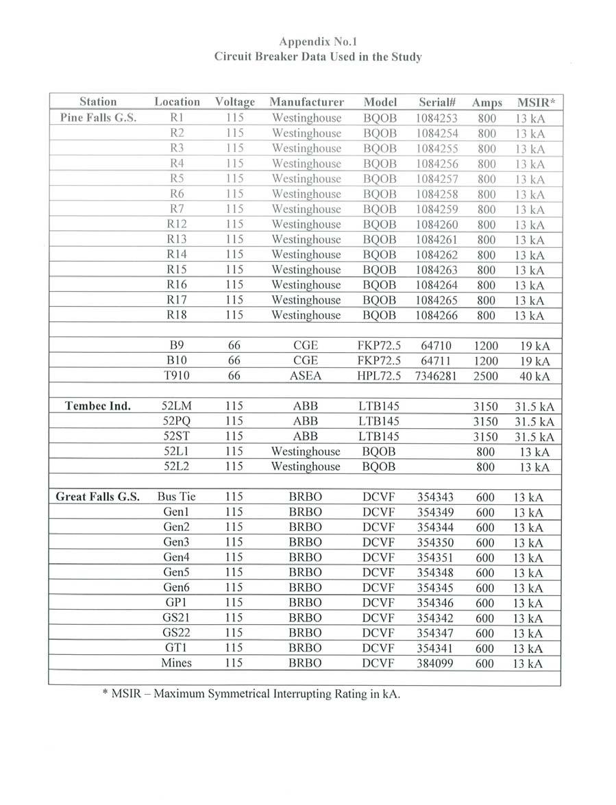
62 62
Section 5. TADS Data Reporting Instruction Manual DRAFT Section 5 and Associated Appendices With Proposed Event Type Numbers
 Section 5 TADS Data Reporting Instruction Manual DRAFT Section 5 and Associated Appendices With Proposed Event Type Numbers Rev. 5/10/2010 1 Section 5 Form for Event ID and Event Type Number Data TO s
System Impact Assessment Addendum #2 Greenfield & St. Clair Energy Centres
 IESO_REP_0292 System Impact Assessment Addendum #2 Greenfield & St. lair Energy entres onnection Assessment & Approval Process Issue 3.0 Greenfield Energy entre AA I 2004-167 Applicant: Greenfield Energy
ECE 585 Power System Stability
 Homework 1, Due on January 29 ECE 585 Power System Stability Consider the power system below. The network frequency is 60 Hz. At the pre-fault steady state (a) the power generated by the machine is 400
B.E. / B.Tech. Degree Examination, April / May 2010 Sixth Semester. Electrical and Electronics Engineering. EE 1352 Power System Analysis
 B.E. / B.Tech. Degree Examination, April / May 2010 Sixth Semester Electrical and Electronics Engineering EE 1352 Power System Analysis (Regulation 2008) Time: Three hours Answer all questions Part A (10
Chapter 9: Transient Stability
 Chapter 9: Transient Stability 9.1 Introduction The first electric power system was a dc system built by Edison in 1882. The subsequent power systems that were constructed in the late 19 th century were
UNITED STATES OF AMERICA BEFORE THE FEDERAL ENERGY REGULATORY COMMISSION. Interconnection for Wind Energy ) Docket No. RM
 Docket No. RM") UNITED STATES OF AMERICA BEFORE THE FEDERAL ENERGY REGULATORY COMMISSION Interconnection for Wind Energy ) Docket No. RM05-4-000 REQUEST FOR REHEARING OF THE NORTH AMERICAN ELECTRIC RELIABILITY COUNCIL
UNITED STATES OF AMERICA BEFORE THE FEDERAL ENERGY REGULATORY COMMISSION Interconnection for Wind Energy ) Docket No. RM05-4-000 REQUEST FOR REHEARING OF THE NORTH AMERICAN ELECTRIC RELIABILITY COUNCIL
Module 6 : Preventive, Emergency and Restorative Control. Lecture 27 : Normal and Alert State in a Power System. Objectives
 Module 6 : Preventive, Emergency and Restorative Control Lecture 27 : Normal and Alert State in a Power System Objectives In this lecture you will learn the following Different states in a power system
Effects of Capacitor Bank Installation in a Medium Voltage (MV) Substation
 Substation") Effects of Capacitor Bank Installation in a Medium Voltage (MV) Substation Adesina, Lambe Mutalub Department of Engineering & Standardization, Eko Electricity Distribution Plc, 24/25, Marina, Lagos Island,
Effects of Capacitor Bank Installation in a Medium Voltage (MV) Substation Adesina, Lambe Mutalub Department of Engineering & Standardization, Eko Electricity Distribution Plc, 24/25, Marina, Lagos Island,
EE2351 POWER SYSTEM OPERATION AND CONTROL UNIT I THE POWER SYSTEM AN OVERVIEW AND MODELLING PART A
 EE2351 POWER SYSTEM OPERATION AND CONTROL UNIT I THE POWER SYSTEM AN OVERVIEW AND MODELLING PART A 1. What are the advantages of an inter connected system? The advantages of an inter-connected system are
QUESTION BANK ENGINEERS ACADEMY. Power Systems Power System Stability 1
 ower ystems ower ystem tability QUETION BANK. A cylindrical rotor generator delivers 0.5 pu power in the steady-state to an infinite bus through a transmission line of reactance 0.5 pu. The generator no-load
Micro-grid to System Synchronization Based on Pre-Insertion Impedance Method (Version 1.0) By Peter Zhou University of Alberta Jan 30 th, 2015
 By Peter Zhou University of Alberta Jan 30 th, 2015") Micro-grid to System Synchronization Based on Pre-Insertion Impedance Method (Version 1.0) By Peter Zhou University of Alberta Jan 30 th, 2015 Outline 1. What is Synchronization? 2. Synchronization Concerns?
Micro-grid to System Synchronization Based on Pre-Insertion Impedance Method (Version 1.0) By Peter Zhou University of Alberta Jan 30 th, 2015 Outline 1. What is Synchronization? 2. Synchronization Concerns?
Power System Analysis Prof. A. K. Sinha Department of Electrical Engineering Indian Institute of Technology, Kharagpur
 Power System Analysis Prof. A. K. Sinha Department of Electrical Engineering Indian Institute of Technology, Kharagpur Lecture - 9 Transmission Line Steady State Operation Welcome to lesson 9, in Power
KINGS COLLEGE OF ENGINEERING Punalkulam
 KINGS COLLEGE OF ENGINEERING Punalkulam 613 303 DEPARTMENT OF ELECTRICAL AND ELECTRONICS ENGINEERING POWER SYSTEM ANALYSIS QUESTION BANK UNIT I THE POWER SYSTEM AN OVERVIEW AND MODELLING PART A (TWO MARK
Module 3 : Sequence Components and Fault Analysis
 Module 3 : Sequence Components and Fault Analysis Lecture 12 : Sequence Modeling of Power Apparatus Objectives In this lecture we will discuss Per unit calculation and its advantages. Modeling aspects
Reliability of Bulk Power Systems (cont d)
") Reliability of Bulk Power Systems (cont d) Important requirements of a reliable electric power service Voltage and frequency must be held within close tolerances Synchronous generators must be kept running
Reliability of Bulk Power Systems (cont d) Important requirements of a reliable electric power service Voltage and frequency must be held within close tolerances Synchronous generators must be kept running
EE 451 Power System Stability
 EE 451 Power System Stability Power system operates in synchronous mode Power system is subjected to a wide range of disturbances (small and large) - Loads and generation changes - Network changes - Faults
7. Transient stability
 1 7. Transient stability In AC power system, each generator is to keep phase relationship according to the relevant power flow, i.e. for a certain reactance X, the both terminal voltages V1and V2, and
SSC-JE EE POWER SYSTEMS: GENERATION, TRANSMISSION & DISTRIBUTION SSC-JE STAFF SELECTION COMMISSION ELECTRICAL ENGINEERING STUDY MATERIAL
 1 SSC-JE STAFF SELECTION COMMISSION ELECTRICAL ENGINEERING STUDY MATERIAL Power Systems: Generation, Transmission and Distribution Power Systems: Generation, Transmission and Distribution Power Systems:
GENERATOR INTERCONNECTION APPLICATION
 GENERATOR INTERCONNECTION APPLICATION FOR BUY-ALL/SELL-ALL PROJECTS WITH AGGREGATE GENERATOR OUTPUT OF MORE THAN 20 KW BUT LESS THAN OR EQUAL TO 1 MW Electric Utility Contact Information Great Lakes Energy
ECE 325 Electric Energy System Components 7- Synchronous Machines. Instructor: Kai Sun Fall 2015
 ECE 325 Electric Energy System Components 7- Synchronous Machines Instructor: Kai Sun Fall 2015 1 Content (Materials are from Chapters 16-17) Synchronous Generators Synchronous Motors 2 Synchronous Generators
Power System Stability and Control. Dr. B. Kalyan Kumar, Department of Electrical Engineering, Indian Institute of Technology Madras, Chennai, India
 Power System Stability and Control Dr. B. Kalyan Kumar, Department of Electrical Engineering, Indian Institute of Technology Madras, Chennai, India Contents Chapter 1 Introduction to Power System Stability
EDSA IEC 909 SHORT CIRCUIT ANALYSIS
 1.0 Tutorial Exercise This tutorial exercise will serve as a validation and verification test for the EDSA IEC 909 short circuit program. The tutorial will be based on two examples documented in the IEC
DISTANCE RELAY SETTINGS
 DISTANCE RELAY SETTINGS Introduction Commonly used >33kV Determine whether impedance measured is within set characteristic. Non-unit protection (boundaries not defined) During normal operation impedance
Request Ensure that this Instruction Manual is delivered to the end users and the maintenance manager.
 Request Ensure that this Instruction Manual is delivered to the end users and the maintenance manager. 1 -A - Introduction - Thank for your purchasing MITSUBISHI ELECTRIC MELPRO TM D Series Digital Protection
Pursuant to Section 205 of the Federal Power Act ( FPA ) 1 and the Commission s
 1 and the Commission s") PJM Interconnection 2750 Monroe Boulevard Norristown, PA 19403-2497 Steven R. Pincus Associate General Counsel 610.666.4370 fax 610.666.8211 steven.pincus@pjm.com July 31, 2017 Honorable Kimberly D. Bose
PJM Interconnection 2750 Monroe Boulevard Norristown, PA 19403-2497 Steven R. Pincus Associate General Counsel 610.666.4370 fax 610.666.8211 steven.pincus@pjm.com July 31, 2017 Honorable Kimberly D. Bose
EE 6501 POWER SYSTEMS UNIT I INTRODUCTION
 EE 6501 POWER SYSTEMS UNIT I INTRODUCTION PART A (2 MARKS) 1. What is single line diagram? A Single line diagram is diagrammatic representation of power system in which the components are represented by
CHAPTER 5 SIMULATION AND TEST SETUP FOR FAULT ANALYSIS
 47 CHAPTER 5 SIMULATION AND TEST SETUP FOR FAULT ANALYSIS 5.1 INTRODUCTION This chapter describes the simulation model and experimental set up used for the fault analysis. For the simulation set up, the
1. Explain the various methods of methods of grounding. In power system, grounding or earthing means connecting frame of electrical equipment (non-cur
 1. Explain the various methods of methods of grounding. In power system, grounding or earthing means connecting frame of electrical equipment (non-current carrying part) or some electrical part of the
Power System Stability GENERATOR CONTROL AND PROTECTION
 Power System Stability Outline Basis for Steady-State Stability Transient Stability Effect of Excitation System on Stability Small Signal Stability Power System Stabilizers Speed Based Integral of Accelerating
A COMPUTER PROGRAM FOR SHORT CIRCUIT ANALYSIS OF ELECTRIC POWER SYSTEMS
 NIJOTECH VOL. 5 NO. 1 MARCH 1981 EJEBE 46 A COMPUTER PROGRAM FOR SHORT CIRCUIT ANALYSIS OF ELECTRIC POWER SYSTEMS BY G.C. EJEBE DEPARTMENT OF ELECTRICAL/ELECTRONIC ENGINEERING UNIVERSITY OF NIGERIA, NSUKKA.
Chapter 3 AUTOMATIC VOLTAGE CONTROL
 Chapter 3 AUTOMATIC VOLTAGE CONTROL . INTRODUCTION TO EXCITATION SYSTEM The basic function of an excitation system is to provide direct current to the field winding of the synchronous generator. The excitation
1. Introduction. Keywords Transient Stability Analysis, Power System, Swing Equation, Three-Phase Fault, Fault Clearing Time
 Energy and Power 17, 7(1): -36 DOI: 1.593/j.ep.1771.3 Numerical Simulations for Transient Stability Analysis of Two-Machine Power System Considering Three-Phase Fault under Different Fault Clearing Times
Outage Coordination and Business Practices
 Outage Coordination and Business Practices 1 2007 Objectives What drove the need for developing a planning/coordination process. Why outage planning/coordination is crucial and important. Determining what
Optimal Placement & sizing of Distributed Generator (DG)
") Chapter - 5 Optimal Placement & sizing of Distributed Generator (DG) - A Single Objective Approach CHAPTER - 5 Distributed Generation (DG) for Power Loss Minimization 5. Introduction Distributed generators
Chapter - 5 Optimal Placement & sizing of Distributed Generator (DG) - A Single Objective Approach CHAPTER - 5 Distributed Generation (DG) for Power Loss Minimization 5. Introduction Distributed generators
ECEN 667 Power System Stability Lecture 20: Oscillations, Small Signal Stability Analysis
 ECEN 667 Power System Stability Lecture 20: Oscillations, Small Signal Stability Analysis Prof. Tom Overbye Dept. of Electrical and Computer Engineering Texas A&M University, overbye@tamu.edu 1 Announcements
RESULTS OF ON-GRID OPERATION OF SUPERCONDUCTOR DYNAMIC SYNCHRONOUS CONDENSER
 1 RESULTS OF ON-GRID OPERATION OF SUPERCONDUCTOR DYNAMIC SYNCHRONOUS CONDENSER Dr. Swarn S. Kalsi, David Madura, and Michael Ross American Superconductor Corporation (USA) Abstract: A high-temperature
Correlation between Lightning Impacts and Outages of Transmission Lines. H-D. BETZ Nowcast GmbH Munich Germany
 CIGRE C4 Colloquium on Power Quality and Lightning Sarajevo, Bosnia and Herzegovina, 13 16 May, 2012 Paper 01. Correlation between Lightning Impacts and Outages of Transmission Lines I. UGLEŠIĆ V. MILARDIĆ
Dynamic simulation of a five-bus system
 ELEC0047 - Power system dynamics, control and stability Dynamic simulation of a five-bus system Thierry Van Cutsem t.vancutsem@ulg.ac.be www.montefiore.ulg.ac.be/~vct November 2017 1 / 16 System modelling
International Studies about the Grid Integration of Wind Generation
 International Studies about the Grid Integration of Wind Generation Dr.-Ing. Markus Pöller/DIgSILENT GmbH Internation Studies About Grid Integration of Wind Generation Grid Integration of Wind Generationin
Final Exam, Second Semester: 2015/2016 Electrical Engineering Department
 Philadelphia University Faculty of Engineering Student Name Student No: Serial No Final Exam, Second Semester: 2015/2016 Electrical Engineering Department Course Title: Power II Date: 21 st June 2016 Course
EFFECTS OF EHV POWER CIRCUIT BREAKER RECLOSING ON POWER SYSTEM STABILITY
 EFFECTS OF EHV POWER CIRCUIT BREAKER RECLOSING ON POWER SYSTEM STABILITY A THESIS Presented to The Faculty of the Division of Graduate Studies By U. C. Roumillat, Jr. In Partial Fulfillment of the Requirements
Peterborough Distribution Inc Ashburnham Drive, PO Box 4125, Station Main Peterborough ON K9J 6Z5
 Peterborough Distribution Inc. 1867 Ashburnham Drive, PO Box 4125, Station Main Peterborough ON K9J 6Z5 November 15, 2017 Ontario Energy Board PO Box 2319 27 th Floor, 2300 Yonge St Toronto ON M4P 1E4
EE2351 POWER SYSTEM ANALYSIS UNIT I: INTRODUCTION
 EE2351 POWER SYSTEM ANALYSIS UNIT I: INTRODUCTION PART: A 1. Define per unit value of an electrical quantity. Write equation for base impedance with respect to 3-phase system. 2. What is bus admittance
From now, we ignore the superbar - with variables in per unit. ψ ψ. l ad ad ad ψ. ψ ψ ψ
 From now, we ignore the superbar - with variables in per unit. ψ 0 L0 i0 ψ L + L L L i d l ad ad ad d ψ F Lad LF MR if = ψ D Lad MR LD id ψ q Ll + Laq L aq i q ψ Q Laq LQ iq 41 Equivalent Circuits for
Mitigation of Distributed Generation Impact on Protective Devices in a Distribution Network by Superconducting Fault Current Limiter *
 Energy and Power Engineering, 2013, 5, 258-263 doi:10.4236/epe.2013.54b050 Published Online July 2013 (http://www.scirp.org/journal/epe) Mitigation of Distributed Generation Impact on Protective Devices
Comparative Study of Synchronous Machine, Model 1.0 and Model 1.1 in Transient Stability Studies with and without PSS
 Comparative Study of Synchronous Machine, Model 1.0 and Model 1.1 in Transient Stability Studies with and without PSS Abhijit N Morab, Abhishek P Jinde, Jayakrishna Narra, Omkar Kokane Guide: Kiran R Patil
O Plus Dry Bushing 69 kv system, 350 kv BIL, 3000 A. Table of contents
 Type test report O Plus Dry Bushing 69 kv system, 0 kv BIL, 000 A Table of contents Abstract... 2 2 Certification... 2 Introduction.... Description and ratings....2 Overview of tests.... Applicable standards....4
POWER SYSTEM STABILITY
 LESSON SUMMARY-1:- POWER SYSTEM STABILITY 1. Introduction 2. Classification of Power System Stability 3. Dynamic Equation of Synchronous Machine Power system stability involves the study of the dynamics
SINGLE OBJECTIVE RISK- BASED TRANSMISSION EXPANSION
 Vol.2, Issue.1, Jan-Feb 2012 pp-424-430 ISSN: 2249-6645 SINGLE OBJECTIVE RISK- BASED TRANSMISSION EXPANSION V.Sumadeepthi 1, K.Sarada 2 1 (Student, Department of Electrical and Electronics Engineering,
Hydra Fault Current Limiting HTS Cable to be Installed in the Consolidated Edison Grid
 Hydra Fault Current Limiting HTS Cable to be Installed in the Consolidated Edison Grid J. McCall, J. Yuan, D. Folts, N. Henderson, American Superconductor D. Knoll, Southwire M. Gouge, R. Duckworth, J.
Economic Operation of Power Systems
 Economic Operation of Power Systems Section I: Economic Operation Of Power System Economic Distribution of Loads between the Units of a Plant Generating Limits Economic Sharing of Loads between Different
THE UNIVERSITY OF NEW SOUTH WALES. School of Electrical Engineering & Telecommunications FINALEXAMINATION. Session
 Name: Student ID: Signature: THE UNIVERSITY OF NEW SOUTH WALES School of Electrical Engineering & Telecommunications FINALEXAMINATION Session 00 ELEC46 Power System Analysis TIME ALLOWED: 3 hours TOTAL
Weekly Operational Constraints Update
 Weekly Operational Constraints Update Applicable from 19 November 2018 to 25 November 2018 (Week 47) 16 November 2018 Disclaimer EirGrid plc, the Transmission System Operator (TSO) for Ireland, and SONI
Transient Stability Assessment of Synchronous Generator in Power System with High-Penetration Photovoltaics (Part 2)
") Journal of Mechanics Engineering and Automation 5 (2015) 401-406 doi: 10.17265/2159-5275/2015.07.003 D DAVID PUBLISHING Transient Stability Assessment of Synchronous Generator in Power System with High-Penetration
Journal of Mechanics Engineering and Automation 5 (2015) 401-406 doi: 10.17265/2159-5275/2015.07.003 D DAVID PUBLISHING Transient Stability Assessment of Synchronous Generator in Power System with High-Penetration
EE Branch GATE Paper 2010
 Q.1 Q.25 carry one mark each 1. The value of the quantity P, where, is equal to 0 1 e 1/e 2. Divergence of the three-dimensional radial vector field is 3 1/r 3. The period of the signal x(t) = 8 is 0.4
1. Wind turbines are designed to operate within specified design criteria. Often the operating environment extends beyond these limits and causes
 1 2 1. Wind turbines are designed to operate within specified design criteria. Often the operating environment extends beyond these limits and causes outages. How these outages are classified can be challenging
For the electronic measurement of current: DC, AC, pulsed..., with galvanic separation between the primary and the secondary circuit.
 Current Transducer LDSR 0.3-TP/SP1 I P R N = 300 ma For the electronic measurement of current: DC, AC, pulsed..., with galvanic separation between the primary and the secondary circuit. Features Closed
SCHOOL OF ELECTRICAL, MECHANICAL AND MECHATRONIC SYSTEMS. Transient Stability LECTURE NOTES SPRING SEMESTER, 2008
 SCHOOL OF ELECTRICAL, MECHANICAL AND MECHATRONIC SYSTEMS LECTURE NOTES Transient Stability SPRING SEMESTER, 008 October 7, 008 Transient Stability Transient stability refers to the ability of a synchronous
Title: Hurst / Littlebrook. Author: Sharon Green Version: 2.0 Date: March SPN Regional Development Plan. Regional Development Plan Page 1 of 24
 Title: SPN Author: Sharon Green Version: 2.0 Date: March 2014 Page 1 of 24 Document History Version Date Revision Class Originator Section Update Details 1.0 23/06/2013 S. Green First Draft for review
Chapter 2. Planning Criteria. Turaj Amraee. Fall 2012 K.N.Toosi University of Technology
 Chapter 2 Planning Criteria By Turaj Amraee Fall 2012 K.N.Toosi University of Technology Outline 1- Introduction 2- System Adequacy and Security 3- Planning Purposes 4- Planning Standards 5- Reliability
Grid Issues and Challenges Addressed by High Temperature Superconductor (HTS) Technology
 Technology") CIGRÉ US National Committee 21, rue d Artois, F-75008 PARIS Grid of the Future Symposium http : //www.cigre.org Kansas City, October 28-30, 2012 Grid Issues and Challenges Addressed by High Temperature
CIGRÉ US National Committee 21, rue d Artois, F-75008 PARIS Grid of the Future Symposium http : //www.cigre.org Kansas City, October 28-30, 2012 Grid Issues and Challenges Addressed by High Temperature
A. P. Sakis Meliopoulos and George J. Cokkinides Power System Relaying, Theory and Applications. Chapter 8 2 Generator Protection 2
 DRAFT and INCOMPLETE Table of Contents from A. P. Sakis Meliopoulos and George J. Cokkinides Power System Relaying, Theory and Applications Chapter 8 Generator Protection 8. Introduction 8. Generator Protection
Using a TCSC for Line Power Scheduling and System Oscillation Damping Small Signal and Transient Stability Studies
 Using a TCSC for Line Power Scheduling and System Oscillation Damping Small Signal and Transient Stability Studies Nelson Martins - CEPEL Herminio Pinto - CEPEL John J. Paserba - Mitsubishi Electric Products,
Power System Security. S. Chakrabarti
 Power System Security S. Chakrabarti Outline Introduction Major components of security assessment On-line security assessment Tools for contingency analysis DC power flow Linear sensitivity factors Line
THIRD GENERATION SYSTEM PROTECTION SCHEME PROJECT FOR ZEYA HYDRO POWER PLANT
 THIRD GENERATION SYSTEM PROTECTION SCHEME PROJECT FOR ZEYA HYDRO POWER PLANT Andrey GROBOVOY Power System Emergency Control Laboratory Ltd. - Russia andrey.grobovoy@ieee.org Elena DEDUKHINA Zeya Hydro
Eddy Current Heating in Large Salient Pole Generators
 Eddy Current Heating in Large Salient Pole Generators C.P.Riley and A.M. Michaelides Vector Fields Ltd., 24 Bankside, Kidlington, Oxford OX5 1JE, UK phone: (+44) 1865 370151, fax: (+44) 1865 370277 e-mail:
Mathematical Modeling and Dynamic Simulation of a Class of Drive Systems with Permanent Magnet Synchronous Motors
 Applied and Computational Mechanics 3 (2009) 331 338 Mathematical Modeling and Dynamic Simulation of a Class of Drive Systems with Permanent Magnet Synchronous Motors M. Mikhov a, a Faculty of Automatics,
Technical Requirements. Version No. 1.0 Effective Date 10/1/2008
 PURPOSE This document applies to wind Generators and describes technical standards that such wind Generators must satisfy to be qualified as a Participating Intermittent Resource (PIR) under the CAISO
Fault Calculation Methods
 ELEC9713 Industrial and Commercial Power Systems Fault Calculation Methods There are two major problems that can occur in electrical systems: these are open circuits and short circuits. Of the two, the
Role of Synchronized Measurements In Operation of Smart Grids
 Role of Synchronized Measurements In Operation of Smart Grids Ali Abur Electrical and Computer Engineering Department Northeastern University Boston, Massachusetts Boston University CISE Seminar November
INSTITUTE OF AERONAUTICAL ENGINEERING (Autonomous)
") INSTITUTE OF AERONAUTICAL ENGINEERING (Autonomous) Dundigal, Hyderabad - 500 043 ELECTRICAL AND ELECTRONICS ENGINEERING QUESTION BANK Course Name : Computer Methods in Power Systems Course Code : A60222
INSTITUTE OF AERONAUTICAL ENGINEERING (Autonomous) Dundigal, Hyderabad - 500 043 ELECTRICAL AND ELECTRONICS ENGINEERING QUESTION BANK Course Name : Computer Methods in Power Systems Course Code : A60222
ECE 422/522 Power System Operations & Planning/Power Systems Analysis II : 7 - Transient Stability
 ECE 4/5 Power System Operations & Planning/Power Systems Analysis II : 7 - Transient Stability Spring 014 Instructor: Kai Sun 1 Transient Stability The ability of the power system to maintain synchronism
TRANSMISSION LINES. All aluminum alloy conductor (AAAC) Aluminum conductor alloy reinforced (ACAR)
 Aluminum conductor alloy reinforced (ACAR)") TRANSMISSION LINES. Transmission Structures An overhead transmission line consists of conductor, insulators, support structures and in most cases shield wires. Overhead power transmission lines are classified
TRANSMISSION LINES. Transmission Structures An overhead transmission line consists of conductor, insulators, support structures and in most cases shield wires. Overhead power transmission lines are classified
Commissioning and Testing of AVR and PSS
 Commissioning and Testing of AVR and PSS Excitation System Upgrade and commissioning challenges Vetti Bala Principal C&I Engineer G E N E S I S E N E R G Y L I M I T E D Contents Asset Testing - AVR AVR
Harmonic Modeling of Networks
 Harmonic Modeling of Networks Thomas H. Ortmeyer ECE Dept. Clarkson University Potsdam, NY 13699-5720 M. Fayyaz Akram Dept. of Elec. Eng. Univ. of Engineering and Technology Lahore, Pakistan Takashi Hiyama
EVALUATION OF THE IMPACT OF POWER SECTOR REFORM ON THE NIGERIA POWER SYSTEM TRANSIENT STABILITY
 EVALUATION OF THE IMPACT OF POWER SECTOR REFORM ON THE NIGERIA POWER SYSTEM TRANSIENT STABILITY F. I. Izuegbunam * Department of Electrical & Electronic Engineering, Federal University of Technology, Imo
O Plus Dry Bushing 25 kv system, 150 kv BIL, 3000 A
 TYPE TEST REPORT O Plus Dry Bushing 25 kv system, 150 kv BIL, 3000 A 02 1 Abstract 02 2 Certification 03 3 Introduction 03 3.1 Description and ratings 03 3.2 Overview of tests 03 3.3 Applicable standards
A New Novel of transverse differential protection Scheme
 A New Novel of transverse differential protection Scheme Li Xiaohua, Yin Xianggen, Zhang Zhe, Chen Deshu Dept of Electrical Engineering, Huazhong University of science and technology, Wuhan Hubei, 430074,
Dynamic Behavior of Three phase Inductions Motors as Loads in an Electric Power System with Distributed Generation, a Case of Study.
 Dynamic Behavior of Three phase Inductions Motors as Loads in an Electric Power System with Distributed Generation, a Case of Study. Marcelo Rodrigo García Saquicela, Ernesto Ruppert Filho, José Luis Azcue
Estimation of Current Transformer Insulation Life with an Effect of Environmental Variables
 Estimation of Current Transformer Insulation Life with an Effect of Environmental Variables Priti N. Bawankule 1, Dr. A. G. Thosar 2, P. S. Swami 3 PG Student [EPS], Dept. of EE, Government College of
PUB NLH 185 Island Interconnected System Supply Issues and Power Outages Page 1 of 9
 PUB NLH 1 Page 1 of 1 Q. Provide Hydro s list of outage cause codes and indicate how troublemen are managed and trained to properly use the codes. Explain the method used to report outage causes. A. Hydro
Studies on hyper scaling dielectric loss of grading capacitors of 500kv breakers
 Studies on hyper scaling dielectric loss of grading capacitors of 500kv breakers Abstract: To solve the problem of hyper scaling dielectric loss of grading capacitors for 500 kv high voltage substation
High Voltage Capacitors Designed to Avoid Catastrophic Failure Modes
 GENERAL ATOMICS ENERGY PRODUCTS Engineering Bulletin High Voltage Capacitors Designed to Avoid Catastrophic Failure Modes F. W. MacDougall G. L. McKee, J.B. Ennis, R.A. Cooper Maxwell Energy Products,
February Industry Communique
 February 2019 Industry Communique Important notice PURPOSE This communique is to inform on the planned outages required in the North-West Victorian and South-West New South Wales transmission network and
Research Paper ANALYSIS OF POWER SYSTEM STABILITY FOR MULTIMACHINE SYSTEM D. Sabapathi a and Dr. R. Anita b
 Research Paper ANALYSIS OF POWER SYSTEM STABILITY FOR MULTIMACHINE SYSTEM D. Sabapathi a and Dr. R. Anita b Address for Correspondence a Research Scholar, Department of Electrical & Electronics Engineering,
Data Bulletin. SEPAM 49RMS Application Note Protection for Motor Applications Class Number SEPAM 49RMS Protection for Motor Applications
 Data Bulletin 3000DB08 09/008 LaVergne, TN, USA SEPAM 49RMS Application Note Protection for Motor Applications Class Number 3000 SEPAM 49RMS Protection for Motor Applications Introduction Thermal protection
Selecting the current rating for equipment
 Selecting the current rating for equipment 1. Rated current: the maximum continuous load current. Short-time withstand current: thermal withstand current term term is given for 1s or 3s short circuit current
Single Phase Motors Technical Datasheets
 Single Phase Motors Technical Datasheets EN A dynamic, strong and ambitious Group: Orange1 Holding is an international renown Group, one of the most important European manufacturers of single-phase and
Generators. What its all about
 Generators What its all about How do we make a generator? Synchronous Operation Rotor Magnetic Field Stator Magnetic Field Forces and Magnetic Fields Force Between Fields Motoring Generators & motors are
POWER SEMICONDUCTOR BASED ELECTRIC DRIVES
 POWER SEMICONDUCT BASED ELECTRIC DRIVES [Time: 3 Hrs] [Max. Marks: 80] Instructions: Solve any six questions from Q.No (1 or 2), Q.No (3 or 4), Q.No (5 or 6), Q.No (7 or 8), Q.No (9 or 10), Q.No (11 or
F F FAULT CURRENT Prospective. 1. Introduction. 2. Types of fault conditions
 FAULT CURRENT F F13-13 FAULT CURRENT - Contents 1. Introduction 2. Types of fault conditions 3 fault current must be determined 3.1 Purposes for which of prospective fault current magnitudes are used 3.2
Test Case: Power System Voltage Stability
 Test Case: Power System Voltage Stability Mats Larsson Corporate Research Mats Larsson / 2002-02-18 / 1 2002 Corporate Research Ltd, Baden, Switzerland Preview The People from Characteristics of Power
Transient Stability Analysis of Single Machine Infinite Bus System by Numerical Methods
 International Journal of Electrical and Electronics Research ISSN 348-6988 (online) Vol., Issue 3, pp: (58-66), Month: July - September 04, Available at: www.researchpublish.com Transient Stability Analysis
Dynamics of the synchronous machine
 ELEC0047 - Power system dynamics, control and stability Dynamics of the synchronous machine Thierry Van Cutsem t.vancutsem@ulg.ac.be www.montefiore.ulg.ac.be/~vct October 2018 1 / 38 Time constants and
, and ignoring all load currents, determine
 ECE43 Test 3 Dec 8, 5 Q. (33 pts.) The Zbus for the above 3-bus network with bus as reference, in per unit, is given to be 3.87 j.798 j.8 j Z.798 j.87 j.8 j bus.8 j.8 j j Assuming that the prefault values
HiLumi LHC FP7 High Luminosity Large Hadron Collider Design Study. Milestone Report. Cryogenic Scenarios for the Cold Powering System
 CERN-ACC-2014-0065 HiLumi LHC FP7 High Luminosity Large Hadron Collider Design Study Milestone Report Cryogenic Scenarios for the Cold Powering System Ballarino, A (CERN) et al 27 May 2014 The HiLumi LHC
Electric Machines I Three Phase Induction Motor. Dr. Firas Obeidat
 Electric Machines I Three Phase Induction Motor Dr. Firas Obeidat 1 Table of contents 1 General Principles 2 Construction 3 Production of Rotating Field 4 Why Does the Rotor Rotate 5 The Slip and Rotor
GATE 2010 Electrical Engineering
 GATE 2010 Electrical Engineering Q.1 Q.25 carry one mark each 1. The value of the quantity P, where P = xe dx, is equal to (A) 0 (B) 1 (C) e (D) 1/e 2. Divergence of the three-dimensional radial vector
74HC2G16; 74HCT2G16. The 74HC2G16; 74HCT2G16 is a high-speed Si-gate CMOS device. The 74HC2G16; 74HCT2G16 provides two buffers.
 Rev. 1 2 November 2015 Product data sheet 1. General description The is a high-speed Si-gate CMOS device. The provides two buffers. 2. Features and benefits 3. Ordering information Wide supply voltage
Power System Seminar Presentation Wind Forecasting and Dispatch 7 th July, Wind Power Forecasting tools and methodologies
 Power System Seminar Presentation Wind Forecasting and Dispatch 7 th July, 2011 Wind Power Forecasting tools and methodologies Amanda Kelly Principal Engineer Power System Operational Planning Operations