CITY OF PETALUMA. POST OFFICE Box 61 PETALUMA, CA ADDENDUM NO. 1
|
|
|
- Bernard Harrison
- 5 years ago
- Views:
Transcription
1 CITY OF PETALUMA POST OFFICE Box 61 PETALUMA, CA David Glass Mayor Chris Alhutson Teresa Barrett Mike Healy Gabe Kearney Dave King Kathy Miller Councilmembers ADDENDUM NO. 1 ONSITE VEHICULAR ACCESS BRIDGE OVER ELLIS CREEK City Project No. C December 14th, 2018 This Addendum No. 1 modifies the Bidding Documents for the Onsite Vehicular Access Bridge Over Ellis Creek Project, City Project No. C , and shall become part of the Contract Documents for this Project. I. TECHNICAL SPECIFICATIONS: Refer to SECTION 300- RAIL CAR BRIDGE, 300C MATERIALS: Public Works & Utilities City Engineer II English Sh eet Petaluma, CA Phone (707) Environmental Services Ellis Creek Water Recycling Facility 3890 Cypress Drive Petaluma, CA Phone (707) Fax: (707) Parks & Facility Maintenance 840 Hopper St. Ext. Petaluma, CA Phone (707) Fax (707) Transit Division 555 N. McDowell Blvd. Petaluma, CA Phone (707) Utilities & Field Operations 202 N. McDowell Blvd. Petaluma, CA Phone (707) Fax (707) publicworks@ ci.petaluma. ca. us Add the following: "Guardrails to conform with CalTrans Revised Standard Plan RSP A77L2 and Standard Plan A77M1." Refer to SECTION RAIL CAR BRIDGE, 300D CONSTRUCTION: Add the following: "300D-2 FINISH. Sandblast all exposed steel of finished bridge structure prior to installation onsite." Refer to SECTION 420- CAST -IN-PLACE CONCRETE, Part 1.05 Submittals: Remove any requirements for batch testing of submitted materials. II. GEOTECHNICAL ENGINEERING STUDY: Please see attached Geotechnical Engineering Study prepared by Consolidated Engineering Laboratories. pk& Assistant Engineer II Public Works & Utilities Department Attachments: Geotechnical Engineering Study
2 ADDENDUM NO. 1 ONSITE VEHICULAR ACCESS BRIDGE OVER ELLIS CREEK City Project No. C December 14th, 2018 ACKNOWLEDGEMENT Receipt of Addendum No. 1 is hereby acknowledged by (Contractor s Name) on the day of, By: Signature Title Company
3 GEOTECHNICAL ENGINEERING STUDY Ellis Creek Bridge Crossing Ellis Creek Water Recycling Facility 3890 Cypress Drive Petaluma, California Prepared for: City of Petaluma Department of Public Works & Utilities 202 North McDowell Boulevard Petaluma, California Prepared by: Consolidated Engineering Laboratories 2001 Crow Canyon Road, Suite 100 San Ramon, California CEL Project No A

4 December 8, 2015 City of Petaluma Department of Public Works & Utilities 202 North McDowell Boulevard Petaluma, California Attention: Subject: Ms. Erica Ahmann Smithies, P.E., Senior Engineer Geotechnical Engineering Study Ellis Creek Bridge Crossing Ellis Creek Water Recycling Facility 3890 Cypress Drive, Petaluma, California CEL Project No A Dear Ms. Smithies: Consolidated Engineering Laboratories (CEL) has prepared a Geotechnical Engineering Study for the proposed new bridge crossing to be located at the Ellis Creek Water Recycling Facility at 3890 Cypress Drive in Petaluma, California. It is our understanding that the proposed project will consist of the construction of a new vehicle bridge crossing within the existing Ellis Creek Water Recycling Facility. This bridge would cross Ellis Creek and connect the plant s solids processing facilities with the oxidation pond area located on the opposite side of the creek. Transmitted herewith are the results of our findings, conclusions, and recommendations for the design and construction of the proposed bridge foundations, site grading and drainage, utility trench backfilling and pavements. In general, the proposed improvements at the site are considered to be geotechnically feasible provided the recommendations of this report are implemented in the design and construction of the project. Should you or members of the design team have questions or need additional information, please contact Mr. Dare at (925) ; or by at cdare@ce-labs.com. We greatly appreciate the opportunity to be of service to the City of Petaluma and to be involved in the design of this project. Sincerely, CONSOLIDATED ENGINEERING LABORATORIES Corey T. Dare, P.E., G.E. Principal Engineer Eric J. Swenson, G.E., C.E.G. Principal Engineer & Geologist Distribution: 3 plus PDF to Addressee (eahmann@ci.petaluma.ca.us) CTD/EJS:pmf
5 TABLE OF CONTENTS 1.0 INTRODUCTION Purpose and Scope Proposed Development Site Conditions Validity of Report PROCEDURES AND RESULTS Literature Review Field Exploration Laboratory Testing GEOLOGY AND SEISMICITY Geologic Setting Seismic Setting FIELD AND LABORATORY FINDINGS Subsurface Soil Conditions Groundwater GEOLOGIC HAZARDS Seismic Induced Hazards CONCLUSIONS AND ENGINEERING RECOMMENDATIONS Seismic Coefficients Site Grading Utility Trench Construction Bridge Foundations Pavements Observation and Testing During Construction LIMITATIONS AND UNIFORMITY OF CONDITIONS REFERENCES... 22
6 TABLE OF CONTENTS (cont d.) FIGURES Figure 1 Site Vicinity Map Figure 2 Site Plan and Site Geology Map Figure 3 Site Vicinity Geologic Map Figure 4 Regional Fault Map Figure 5 Schematic Geologic Cross-Section A-A Figure 6 Liquefaction Susceptibility Map APPENDIX A FIELD EXPLORATION Key to Exploratory Boring Logs Boring Logs APPENDIX B LABORATORY TEST RESULTS Moisture-Density-Porosity Report (2) Liquid and Plastic Limits Test Report Unconsolidated-Undrained Triaxial Test R-value Test Report (2)
7 GEOTECHNICAL ENGINEERING STUDY Project: Client: Ellis Creek Bridge Crossing Ellis Creek Water Recycling Facility 3890 Cypress Drive, Petaluma, California City of Petaluma Department of Public Works & Utilities 202 North McDowell Boulevard Petaluma, California INTRODUCTION 1.1 Purpose and Scope The purpose of our work was to prepare a Geotechnical Engineering Study, evaluate the subsurface conditions at the site and prepare geotechnical recommendations for the proposed development. We have provided specific recommendations regarding suitability and geotechnical concerns relative to the proposed structural design. The scope of this study included conducting field exploration and laboratory testing programs, engineering analysis of the collected samples and test results, and preparation of this report. The conclusions and recommendations presented in this report are based on the limited samples collected and analyzed during this study, and on prudent engineering judgment and experience. This study did not include an in-depth assessment of potentially toxic or hazardous materials that may currently be present on or beneath the site. 1.2 Proposed Development The proposed improvement project will be within the City of Petaluma s Ellis Creek Water Recycling Facility located southeast of Lakeville Highway in Petaluma, and southwest of Browns Lane, as shown on Figure 1, Site Vicinity Map and Figure 2, Site Plan and Site Geology Map. The proposed construction, at the specific location indicated on Figure 2, will consist of a new vehicular bridge crossing Ellis Creek as well as short, connecting approach roads on each side of the bridge. The intent of the new bridge is to provide direct vehicular access across Ellis Creek between the main portion of the plant and the oxidation pond areas northwest and southeast, respectively, of Ellis Creek where currently access between the two areas requires separate access between the main plant entrance on Cypress Drive and the oxidation pond access gate located on Lakeville Highway. Specific design details of the project were not known at the time this study was performed, but the access roads are assumed to have a flexible pavement (i.e., asphalt concrete and underlying aggregate base) section.
8 Site grading is anticipated to consist of site clearing and grubbing, fill placement to construct subgrades for the approach roads, and excavations for bridge foundation construction. 1.3 Site Conditions The project site is within the existing Ellis Creek Water Recycling Facility (WRF) and is located between the eastern corner of the solids process area and near the northern corner of the oxidation ponds. The site is currently undeveloped, and level to gently sloping toward the creek banks. Survey data provided by the City of Petaluma indicates the top of creek bank elevations at the bridge site to be approximately El and at the southeast and northwest banks, respectively, and about El at the creek bottom. The lateral distance between the top of the creek banks along the proposed bridge alignment is about 45 feet. The southeastern end of the bridge road alignment connects with the existing perimeter levee road of Oxidation Pond No.4, and the northwest end of the bridge alignment connects with the solids process area perimeter loop road. The bridge and road alignment is currently covered by low grasses, and southeast of the creek, a few trees are present. 1.4 Validity of Report This report is valid for three years after publication. If construction begins after this time period, CEL should be contacted to confirm that the site conditions have not changed significantly. If the proposed development differs considerably from that described above, CEL should be notified to determine if additional recommendations are required. Additionally, if CEL is not involved during the geotechnical aspects of construction, this report may become wholly or in part invalid, since CEL s geotechnical personnel need to verify that the subsurface conditions anticipated preparing this report are consistent with the subsurface conditions revealed during construction. CEL s involvement should include bridge foundation and grading plan review; observation of foundation excavations; grading observation and testing; testing of utility trench backfill if any; and observation and testing of road subgrade and pavement section preparation. 2
9 2.0 PROCEDURES AND RESULTS 2.1 Literature Review Pertinent geologic and geotechnical literature pertaining to the site area were reviewed. These included various United States Geological Survey (USGS), California Geological Survey (CGS) and online resources, and other applicable government publications and maps, as included in the References section. 2.2 Field Exploration A total of four borings were drilled at the site on November 6, 2015 at the approximate locations shown on Figure 2. The borings were drilled to between 5 and 50 feet deep. Two of the borings were drilled at the site of the proposed bridge abutments. Two shallow (five-foot deep) borings were drilled along the approach roads on both sides of the bridge. The borings were drilled using a truck mounted drill rig (CME-55) supplied by Clear Heart Drilling of Santa Rosa, California, and equipped with a six-inch diameter, solid-stem flight auger. A CEL field engineer visually classified the materials encountered in the borings according to the Unified Soil Classification System as the borings were advanced. Relatively undisturbed soil samples were recovered at selected intervals using a three-inch outside diameter Modified California split spoon sampler containing six-inch long brass liners. A two-inch outside diameter Standard Penetration Test (SPT) sampler was used to obtain SPT blow counts and obtain disturbed soil samples. The samplers were driven by using a mechanical-trip, 140-pound hammer with an approximate 30-inch fall utilizing N-rods as necessary. Resistance to penetration was recorded in the field as the number of hammer blows required to drive the sampler the final foot of an 18-inch drive. Following the completion of drilling, the boreholes were backfilled using a cement grout in accordance with Sonoma County Permit and Resource Management Department (PRMD) requirements. For reporting purposes, all of the blow counts recorded using Modified California (MC) split spoon samplers in the field were subsequently converted to equivalent SPT blow counts using appropriate modification factors suggested by Burmister (1948); i.e., multiplied by a factor of 0.65 assuming a liner sample with an inner diameter of 2.5 inches. Therefore, all blow counts shown on the final boring logs are either directly measured (SPT sampler) or equivalent SPT (MC sampler) blow counts. The boring logs with descriptions of the various materials encountered in each boring, pocket penetration test resistance values, and some of the laboratory test results are presented in Appendix A. The ground surface 3
10 elevations indicated on the soil boring logs are approximate (i.e., rounded to the nearest foot) and were estimated using existing City of Petaluma survey data. Actual surface elevations at the boring locations may differ slightly. Boring locations were determined in the field by visual orientation in relation to both on-site and off-site physical landmarks. The locations and elevations of the borings should only be considered accurate to the degree implied by the means and methods used to define them. 2.3 Laboratory Testing Laboratory tests were performed on selected samples to determine some of the physical and engineering properties of the subsurface soils. The results of the laboratory testing are presented on the boring logs, and/or included in Appendix B. The following soil tests were performed for this study: Dry Density and Moisture Content (ASTM D2216 and D2937) In-situ density and moisture tests were conducted on several recovered soil samples to determine the in-place dry density and moisture content of the subsurface materials. These properties provide information for evaluating the physical characteristics of the subsurface soil. Test results are presented on the boring logs. Atterberg Limits (ASTM D4318 and CT204) - Liquid Limit, Plastic Limit, and Plasticity Index are useful in the classification and characterization of the engineering properties of soil, helps evaluate the expansive characteristics of the soil, and for determining the soil type according to the USCS. One test was performed, and the test results are presented in Section 4.1, Appendix B, and on the applicable boring log. Unconsolidated-Undrained Compressive Strength Test (ASTM D2850) Unconsolidated-Undrained compression tests were performed on two relatively undisturbed samples of the onsite cohesive subsurface soils to evaluate the undrained shear strength of these materials. The test was performed on samples having a diameter of 2.4 inches and height of about five inches. Failure was taken as the peak normal stress minus the confining pressure (i.e., deviator stress). The results of the tests are presented in Appendix B and on the boring logs at the appropriate sample depths. R-Value Test (ASTM D2844 and CT301) Two R-value tests were conducted on bulk composite samples of nearsurface clayey materials collected from cuttings generated from the borings within approximately the uppermost four feet of the soil profile to provide data on prospective pavement subgrade materials for use in new pavement section design. Test results are presented in Section 6.6 and in Appendix B. 4
11 3.0 GEOLOGY AND SEISMICITY 3.1 Geologic Setting The site is located within the central portion of the Coast Ranges geomorphic province of California on the northwestern side of San Pablo Bay. The Coast Ranges geomorphic province consists of numerous small to moderate linear mountain ranges trending north to south and northwest to southeast. The Coast Ranges province extends approximately 400 miles from the Klamath Mountains to the Santa Ynez River in Santa Barbara County. This province is characterized by northwest-trending faults and folds, erosion and deposition within the broad transform boundary between the North American and Pacific plates. Translational motion along the plate boundary occurs across a distributed zone of right-lateral shear expressed as a nearly 50-mile-wide zone of northwest-trending, near-vertical active strike-slip faults. In the greater San Francisco Bay area, this motion occurs primarily along the active San Andreas, Hayward-Rodgers Creek and Calaveras faults. Historically, the San Francisco Bay region is very seismically active and has been subjected to strong ground shaking from several large earthquakes. In particular, in the Peninsula, the Peninsula and North Coast Section of the San Andreas Fault experienced a M7.8 earthquake in 1906, also known as the Great San Francisco Earthquake of Recently, in the North Bay, the West Napa Fault experienced a M6.1 earthquake in A geologic map of the site vicinity based on Graymer et al. (1994) is presented as Figure 3, Site Vicinity Geologic Map. According to this mapping, the site is underlain by Quaternary-period, Holocene-age alluvium bordering Quaternary-period, late Holocene-age mud deposits associated with the nearby Petaluma River to the southwest. According to a slightly more detailed CGS geologic map prepared by Wagner et al. (2002),the Ellis Creek channel is underlain by late Holocene to modern age (< 150 years old) stream channel deposits consisting of loose alluvial gravel, sand and silt. The Wagner et al. map also shows the soils on both sides of the channel to consist of Holocene alluvial fan deposits consisting of poorly to moderately sorted sand, gravel, silt and clay stream deposits emanating from canyons onto alluvial valley floors. Bedrock, locally consisting of the Mesozoic and early-cenozoic Franciscan Formation, was estimated by Fugro West (2005) to be present at depths of 100 to 300 feet below the site. 3.2 Seismic Setting Regional transpression has caused uplift and folding of the bedrock units within the Coast Ranges. This structural deformation occurred during periods of tectonic activity that began in the Pliocene and continues today. 5
12 Northern California is a seismically active region that has experienced periodic, large magnitude earthquakes during historic times. This seismic activity appears to be largely controlled by displacement between the Pacific and North American crustal plates, separated by the San Andreas Fault zone. This plate displacement produced regional strain that is concentrated along major fault zones of the San Andreas Fault System including the San Andreas, Hayward-Rodgers Creek, and Calaveras Faults. These major fault zones extend through the San Francisco Bay Area in a northwesterly direction and have produced on the order of 12 earthquakes in the last two centuries that were strong enough to cause structural damage. The closest active fault systems include the Rodgers Creek Fault to the northeast, located approximately 3.5 miles from the site at its closest point, and the West Napa Fault, approximately 14.5 miles northeast of the site. In addition, the San Andreas Fault is mapped approximately 17 miles southwest of the site. In addition, the potentially active Tolay Fault has been mapped or inferred by various sources to be on the order of 0.5 miles east of the site (Fugro West, 2005). Faults in the region are shown on Figure 4, Regional Fault Map. In 2007, the Working Group on California Earthquake Probabilities (WGCEP 2007), in conjunction with the United States Geological Survey (USGS), published an updated report evaluating the probabilities of significant earthquakes occurring in the Bay Area over the next three decades. WGCEP 2007 estimated that there is a 93 percent probability that at least one magnitude 6.7 or greater earthquake will occur within the San Francisco Bay region over the next 30 years. This probability is an aggregate value that considered seven principal Bay Area fault systems and unknown faults (i.e., background values). 6
13 4.0 FIELD AND LABORATORY FINDINGS 4.1 Subsurface Soil Conditions Subsurface conditions below the project site were interpreted based on the results of our test borings performed for this study and the results of our laboratory testing. Detailed descriptions of the various subsurface soil units encountered during subsurface explorations are described in the following paragraphs. At the locations of our exploratory Borings B-1 and B-4, situated on the northwest and southeast approach roads, respectively, very stiff clay with fine gravel was encountered to the depth of exploration of about five feet. Boring B-2, drilled at the proposed northwest bridge abutment, encountered medium dense clayey sand to a depth of about nine feet below ground surface (bgs), underlain by very stiff clay to sandy clay to a depth of about 46 feet bgs, in turn underlain by very dense sand to the maximum depth of exploration of 50 feet. Boring B-3, drilled at the proposed southeast bridge abutment, encountered primarily medium dense to dense clayey sand to a depth of about six feet bgs, underlain by medium stiff to stiff silty to sandy clay to a depth of about 13.5 feet, in turn underlain by very stiff sandy clay to the maximum depth of exploration of 30 feet. A subsurface profile along the proposed road and bridge alignment is presented in Figure 5, Schematic Geologic Cross Section A-A. Additional details of soils encountered in the exploratory borings are included in the boring logs provided in Appendix A. One sample of the near-surface clayey soil was tested to measure Atterberg Limits. The sample, taken at a depth of five feet in Boring B-2, had a measured Liquid Limit (LL) of 35, Plastic Limit (PL) of 16 and corresponding Plasticity Index (PI) of 19. Based on the test measurements, the near-surface soils would be considered to be of medium plasticity and moderate expansion potential. 4.2 Groundwater Free groundwater was encountered during drilling in Borings B-2 and B-3 at approximate depths of 18 and 16 feet, respectively, below ground surface during drilling. These depths correspond to El and +2.4 for Borings B-2 and B-3, respectively. The borings were backfilled with a neat cement grout in accordance with Sonoma County Permit Resource Management Department requirements shortly after drilling. We note that the borings may not have been left 7
14 open for a sufficient period of time to establish equilibrium groundwater conditions. Groundwater levels can also vary in response to adjacent river levels, time of year, variations in seasonal rainfall, well pumping, irrigation, and alterations to site drainage. 8
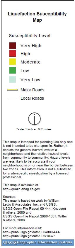
15 5.0 GEOLOGIC HAZARDS 5.1 Seismic Induced Hazards Seismic hazards resulting from the effects of an earthquake generally include ground shaking, liquefaction, lateral spreading, dynamic settlement (densification), fault ground rupture and fault creep, seismic slope failure, and tsunamis and seiches. The site is not necessarily impacted by all of these potential seismic hazards. Applicable potential seismic hazards are discussed and evaluated in the following sections in relation to the planned construction Ground Shaking The site may experience moderate to strong ground shaking from a major earthquake originating from a number of significant faults in the greater San Francisco Bay Area, including the Hayward-Rodgers Creek and San Andreas Faults. Earthquake intensities vary throughout the region depending upon the magnitude of the earthquake, the distance of the site from the causative fault, the type of materials underlying the site and other factors. In addition to shaking of the structure, strong ground shaking can induce other related phenomena that may have an effect on structures, such as liquefaction and dynamic densification settlement Liquefaction Induced Phenomena Research and historical data indicate that soil liquefaction generally occurs in saturated, loose granular soil (primarily fine to medium-grained, clean sand deposits) during or after strong seismic ground shaking and is typified by a loss of shear strength in the affected soil layer, thereby causing the soil to flow as a liquid. However, because of the higher inter-granular pressure of the soil at greater depths, the potential for liquefaction is generally limited to the upper 40 feet of the soil. Potential hazards associated with soil liquefaction below or near a structure include loss of foundation support, lateral spreading, sand boils, and areal and differential settlement. Lateral spreading is lateral ground movement, with some vertical component, as a result of liquefaction. The soil literally rides on top of the liquefied layer. Lateral spreading can occur on relatively flat sites with slopes less than two percent under certain circumstances, generally when the liquefied layer is in relatively close proximity 9
16 to an open, free slope face such as the bank of a creek channel. Lateral spreading can cause surficial ground tension cracking (i.e., lurch cracking) and settlement. Published mapping by the USGS and William Lettis & Associates in cooperation with the CGS shows the creek channel to be an area of very high liquefaction susceptibility, and the creek banks and adjacent areas to have moderate liquefaction susceptibility, as shown on Figure 6, Liquefaction Susceptibility Map. Subsurface soils encountered in our field explorations consisted of essentially cohesive clays and relatively cohesive clayey sands to a depth of 46 feet, below which dense to very dense clean sands were encountered to the maximum depth of exploration of 50 feet. Soils at the bottom of the creek channel were not evaluated, but will be spanned by the proposed bridge and not anticipated to impact the project. Due to the absence of liquefiable soils encountered in the creek bank borings, the potential for significant liquefaction occurring at the bridge abutment locations is judged to be low. Due to the lack of liquefiable soils encountered in the creek bank borings, based on the accumulated data, the potential for lateral spreading of the bank soils into the channel in the event of very strong ground shaking is judged to be low Dynamic Densification (Settlement) Dynamic densification or settlement is a process in which unsaturated, loose, relatively clean sands and silts are densified by the vibratory motion of a strong seismic event. Due to the lack of significant thicknesses of loose sandy soils encountered in our borings above the encountered groundwater table, the potential for significant dynamic densification is judged to be very low Fault Ground Rupture and Fault Creep The State of California adopted the Alquist-Priolo Earthquake Fault Zone Act of 1972 (Chapter 7.5, Division 2, Sections , California Public Resources Code), which regulates development near active faults for the purpose of preventing surface fault rupture hazards to structures for human occupancy. In accordance with the Alquist-Priolo (A-P) Act, the California Geological Survey established boundary zones or Earthquake Fault Zones surrounding faults or fault segments judged to be sufficiently active, well-defined and mapped for some distance. Structures for human occupancy within designated Earthquake Fault Zone boundaries are not permitted unless surface fault rupture and fault creep hazards are adequately addressed in a site-specific 10
17 evaluation of the development site. The site is not currently within a designated Earthquake Fault Zone as defined by the State (Hart and Bryant, 1997). The closest Earthquake Fault Zone is associated with the Rodgers Creek Fault, located about 3. 5 miles to the northeast of the site. Based on our evaluation, in our opinion, the potential for fault ground rupture and/or surface creep at the site is very low. 11
18 6.0 CONCLUSIONS AND ENGINEERING RECOMMENDATIONS The following conclusions and engineering recommendations are based upon the analysis of the information gathered during the course of this study and our understanding of the proposed improvements. The site is considered suitable from a geotechnical and geologic perspective for the proposed improvements provided the recommendations of this report are incorporated into the design and implemented during construction. The predominant geotechnical and geological issues that could affect design or construction at this site are summarized below and addressed in the following sections. Seismic Considerations - The site is located within a seismically active region and the structures should be designed to account for strong ground motion due to earthquake shaking, as described in this report. Potential Unstable Fill Subgrades Depending on time of year, exposed subgrade surfaces may consist of inplace soils significantly above optimum moisture content which may as a result be unstable prior to placement of new fill or compaction as pavement subgrade. Such soils may require stabilization using methods such as over-excavation of the exposed soils to competent stable supporting material, or if not feasible, use of geogrid, stabilization geotextile, or chemical treatment of the subgrade soils using lime or quicklime. Winter Construction - If grading occurs in the winter rainy season, rains may impact foundation excavations, road subgrades, and underground utilities (if any). 6.1 Seismic Coefficients Project structures should be designed in accordance with local design practice to resist the lateral forces generated by ground shaking associated with a major earthquake occurring within the greater Bay Area. Based on the subsurface conditions encountered in our borings and our evaluation of the geology of the site, Site Class D, representative of stiff soils averaged over the uppermost 100 feet of the subsurface profile would be appropriate for this site. Assuming the project is designed in accordance with the seismic provisions of the CBC 2013 and American Society of Civil Engineers (ASCE) 7-10 using Site Class D, the following seismic ground motion values should be used for design. 12
19 Table 1: Seismic Coefficients Based on 2013 CBC (per ASCE 7-10) Item Value 2013 CBC Source R1 ASCE 7-10 Table/Figure R2 Site Class D Chapter 20 Mapped Spectral Response Accelerations Short Period, S s 1-second Period, S g g Figure 22-1 Figure 22-2 Site Coefficient, F a 1.0 Table (1) Table Site Coefficient, F v 1.5 Table (2) Table MCE (S MS ) g Equation Equation MCE (S M1 ) g Equation Equation Design Spectral Response Acceleration Short Period, S DS 1-second Period, S D g g Equation Equation R1 California Building Standards Commission (CBSC), California Building Code, 2013 Edition. R2 U.S. Seismic Design Maps Web Application, Equation Equation ASCE indicates that the Seismic Design Category for Occupancy Category I, II and III structures is E because S 1 > 0.75g. For Seismic Design Category E, additional design parameters are presented in Table 2: Table 2: Additional Seismic Design Parameters Based on 2013 CBC Item ASCE 7-10 Value Table/Figure R2 PGA (Peak Ground Acceleration) 0.783g Figure 22-7 Site Coefficient, F PGA Table PGA M 0.783g Equation C RS Figure C R Figure Site Grading General Grading and Material Requirements Site grading is generally anticipated to consist of clearing and grubbing, plus grading to construct the new roadway subgrades and site bridge foundations as required. On-site soil having an organic content of less than three percent by weight can be reused as general (not select) fill as approved by the Geotechnical Engineer. 13
20 Imported, select soil should be non-expansive, having a Plasticity Index of 15 or less, an R-Value greater than 40, and contain sufficient fines so the soil can bind together. Imported materials should be free of environmental contaminants, organic materials and debris, and should not contain rocks or lumps greater than three inches in maximum size. Import fill materials should be approved by the Geotechnical Engineer prior to use on site Project Compaction Recommendations Table 3 provides the recommended compaction requirements for this project. Depending on final project details, some items listed below may not apply to this project. Specific moisture conditioning and relative compaction requirements may be discussed individually within applicable sections of this report. Description Table 3: Project Compaction Recommendations Minimum Percent Relative Compaction Minimum Percent Above Optimum Moisture Content General Structural Fill 90 3 AC Pavement, Subgrade, Upper AC Pavement, Subgrade Onsite Soil or Fill 90 3 AC Pavement, Class 2 Baserock 95 2 Concrete Hardscape, Class 2 Baserock 90 2 Concrete Hardscape, Subgrade Soil 90 3 Retaining Wall Backfill, upper Retaining Wall Backfill, below Underground Utility Backfill 90 3 Underground Utility Backfill Upper 3 below 95 3 Pavements Underground Utility Backfill, Clean Sand Site Preparation and Demolition Site grading should be performed in accordance with these recommendations. A pre-construction conference should be held at the jobsite with representatives from the owner, general contractor, grading contractor, and CEL prior to starting the stripping and demolition operations at the site. The site should be cleared of vegetation, debris, and other deleterious materials within the proposed development area. 14
21 6.2.4 Subgrade Preparation Following excavation to the required grades, subgrades in areas to receive engineered fill, slabs-on-grade, hardscapes or pavement sections should be scarified to a depth of at least six inches; moisture conditioned, and compacted to the requirements for engineered fill presented in Table 3. The compacted surface should be firm and unyielding and should be protected from damage caused by traffic or weather. Soil subgrades should be kept moist during construction. In order to achieve satisfactory compaction of the subgrade and fill materials, it may be necessary to adjust the water content at the time of construction. This may require that water be added to soils that are too dry, or that scarification and aeration be performed in any soils that are too wet. Fill material should be evenly spread and compacted in lifts not exceeding eight inches in pre-compacted thickness. Newly exposed near-surface clayey soils may be near-saturated to saturated, based on time of year. Therefore, it is possible that unstable subgrade conditions unworkable for compaction by construction equipment may be present, and compaction of the exposed soil subgrade to engineered fill requirements immediately after exposure may not be feasible. Possible options for subgrade stabilization include ripping, air-drying and recompacting exposed subgrade material; admixtures such as lime or quicklime; or use of reinforcing stabilization geotextile or geogrid, as discussed below. More detailed recommendations can be provided during construction should unstable subgrades be encountered by the contractor. Unstable subgrades in smaller, isolated areas can be stabilized by over excavating to a minimum of 18 inch depth below finished subgrade elevation where competent, stable soils are not encountered. The bottom of the excavation should then be completely covered with a ground stabilization geotextile fabric such as Mirafi 500X or equivalent, and typically backfilled with Class 2 aggregate base. Alternatively, with the approval of the Geotechnical Engineer, such areas can be stabilized by over-excavating at least one foot, placing Tensar TriAx TX- 140 or equivalent geogrid on the soil, and then placing at least 12 inches of Class 2 baserock on the geogrid. The upper six inches of the baserock in either case should be compacted to at least 95% relative compaction. 6.3 Utility Trench Construction Utility trenches may be backfilled with onsite soil or import soil pre-approved by the Geotechnical Engineer above the utility bedding and shading materials. Any on-site highly expansive clay soils should be avoided as backfill for trenches. If rocks or concrete larger than four inches in maximum size are encountered, they should be removed from the fill material prior to placement in the utility trenches. 15
22 Pipeline trenches should be backfilled with fill placed in lifts of approximately eight inches in pre-compacted thickness, and compacted to the requirements presented in Table 3. However, thicker lifts can be used, provided the method of compaction is approved by the Geotechnical Engineer, and the required minimum degree of compaction is achieved. If rain is expected and the trench will remain open, the bottom of the trench may be lined with one to two inches of gravel. This would provide a working surface in the trench bottom. The trench bottom may have to be sloped to a low point to pump the water out of the trench. 6.4 Bridge Foundations Bridge foundations should consist of cast-in-drilled hole (CIDH) pier foundations, also referred to as drilled piers, with the piers connected by a grade beam or retaining wall footing. CIDH pier foundations would derive their vertical supporting capacity through skin friction between the side surfaces of the foundations and the adjacent soil. For design purposes, the allowable skin friction (FS = 2) for dead plus live gravity loads may be assumed to be 500 psf. This value may be increased by one-third for seismic or transient loads. Uplift loads should be limited to two-thirds of these values. For piers situated adjacent to or on the creek bank slopes, the portion of pier with horizontal cover less than 10 feet, measured from outside perimeter of the pier to the slope surface or design depth of potential scour erosion, if any, should be neglected in computing vertical capacity. In order to fully mobilize skin friction capacity, vertical settlement on the order of 0.5 percent of the pier diameter would be required. Lateral resistance for drilled pier foundations may be determined for onsite soils using an allowable passive resistance equal to an equivalent fluid weighing 350 pounds per cubic foot (pcf) acting against the foundation for lateral load resistance against the sides of foundations perpendicular to the direction of loading where the foundation is poured neat against undisturbed material. The top foot of passive resistance at foundations should be neglected. For pier foundations, passive pressure can be assumed to act across two times the pier diameter. For piers situated adjacent to or on slopes, the portion of pier with horizontal cover less than 10 feet, measured from outside perimeter of the pier to the slope surface or design depth of potential scour erosion, if any, should be neglected in computing lateral resistance. 16
23 For bridge abutments that incorporate a retaining wall, for a level backfill condition, unrestrained walls (i.e., walls that are free to deflect or rotate) should be designed to resist an equivalent fluid pressure of 35 pounds per cubic foot. Restrained walls for a level backfill condition should be designed to resist an equivalent fluid pressure of 35 pounds per cubic foot, plus an additional uniform lateral pressure of 7H pounds per square foot, where H = height of backfill above the top of the wall footing, in feet. If required for seismic design, unrestrained walls and restrained walls with level backfill and with retained height of more than six feet should be designed to resist an additional uniform load equal to 24H psf. The seismic load increment should be added to the unrestrained condition in both cases. Walls subjected to surcharge loads should be designed for an additional uniform lateral pressure equal to 0.33 times the anticipated surcharge load for unrestrained walls, and 0.50 times the anticipated surcharge load for restrained walls. To account for typical vehicle loads, a surcharge pressure equivalent to two feet of fill (i.e., 250 psf) may be assumed for abutment wall design. Lateral resistance for pier caps or wall footings poured neat against native soil may be determined using an allowable passive resistance equal to an equivalent fluid weighing 350 pounds per cubic foot (pcf) acting against the foundation for lateral load resistance against the sides of foundations perpendicular to the direction of loading where the foundation is poured neat against undisturbed material. The top foot of passive resistance should be neglected. In addition, an allowable coefficient of friction of 0.35 between the base of the foundation elements and underlying material may be used. Retaining wall and wing wall backfill less than five feet deep should be compacted to at least 90 percent relative compaction using light compaction equipment. Backfill greater than a depth of five feet should be compacted to at least 95 percent relative compaction. If heavy compaction equipment is used, the walls should be appropriately designed to withstand loads exerted by the heavy equipment, and/or temporarily braced. Over compaction or surcharge from heavy equipment too close to the wall may cause excessive lateral earth pressures which could result in outward wall movement. 6.5 Pavements Recommendations for the design of asphalt concrete pavement sections were developed in accordance with the procedures outlined in the latest edition of the Caltrans Highway Design Manual. The Caltrans design method 17
24 uses Traffic Indices (TI) to represent anticipated wheel loads and frequency of usage for a given design life. A design life of 20 years is typically used in California. Factors such as surface and subsurface drainage have an effect on the overall life of a pavement section. An R-value of less than 5 was obtained by laboratory tests on representative samples of native near-surface soils taken on both sides of Ellis Creek along the proposed new road alignment. Traffic Indices of 5.0, 6.0 and 7.0 were assumed to be representative of a range of light maintenance truck and occasional heavier vehicle loadings. The following are recommended structural asphalt concrete (AC) pavement sections. Aggregate base (AB) from recycled sources offered by AB suppliers as well as AC grindings mixed with baserock and meeting Class 2 specifications can be utilized in lieu of virgin Class 2 AB upon approval of the Geotechnical Engineer. Table 5: Flexible Pavement Design Alternatives (Native Subgrade) Traffic Index Asphalt Concrete (in.) Class 2 AB (in.) Total Section Thickness (in.) Pavement section thicknesses may be reduced if the uppermost 12 inches of pavement subgrade are lime treated prior to construction of the pavement section. Assuming an R-value of 40 is used to represent the lime treated pavement subgrade soils the pavement section designs presented in Table 6 are suggested. These pavement section design thicknesses may also be used where fill meeting the requirements for import select fill presented in Section is used as road subgrade, as may be the case if existing grades must be raised by at least one foot to construct the new roadway subgrade. Table 6: Flexible Pavement Design Alternatives (Lime Treated Subgrade or Import Select Fill) Traffic Index Asphalt Concrete (in.) Class 2 AB (in.) Total Section Thickness (in.) * *minimum recommended pavement baserock thickness Design based on the aforementioned traffic indices should provide the design pavement life with only a normal amount of pavement maintenance. Selection of the design traffic parameters, however, was based on geotechnical engineering judgment, and not on an equivalent wheel load analysis either developed from a traffic 18
25 study or furnished to us by the project civil engineer. Therefore, the traffic indices provided herein should be confirmed by the civil engineer as appropriate for the intended use. AB for use in flexible pavements should conform to Caltrans Standard Specification Sections A and B (2010) for Class 2 AB. AB used in pavement sections should be compacted to a minimum 95 percent relative compaction (ASTM D1557) and should be firm and unyielding at the time of asphalt concrete placement. 6.6 Observation and Testing During Construction We recommend that CEL be retained to provide observation and testing services during site preparation, site grading, utility trench backfill construction and foundation excavation, and pavement section construction, and to observe final site drainage. This is to observe compliance with the design concepts, specifications and recommendations, and to allow for possible changes in the event that subsurface conditions differ from those anticipated prior to the start of construction. 19
26 7.0 LIMITATIONS AND UNIFORMITY OF CONDITIONS The recommendations of this report are based upon the soil and conditions encountered in the borings. If variations or undesirable conditions are encountered during construction, CEL should be contacted so that supplemental recommendations may be provided. This report is issued with the understanding that it is the responsibility of the owner or his representatives to see that the information and recommendations contained herein are called to the attention of the other members of the design team and incorporated into the plans and specifications, and that the necessary steps are taken to see that the recommendations are implemented during construction. The findings and recommendations presented in this report are valid as of the present time for the development as currently proposed. However, changes in the conditions of the property or adjacent properties may occur with the passage of time, whether by natural processes or the acts of other persons. In addition, changes in applicable or appropriate standards may occur through legislation or the broadening of knowledge. Accordingly the findings and recommendations presented in this report may be invalidated, wholly or in part, by changes outside our control. Therefore, this report is subject to review by CEL after a period of three (3) years has elapsed from the date of issuance of this report. In addition, if the currently proposed design scheme as noted in this report is altered, CEL should be provided the opportunity to review the changed design and provide supplemental recommendations as needed. Recommendations are presented in this report which specifically request that CEL be provided the opportunity to review the project plans prior to construction and that we be retained to provide observation and testing services during construction. The validity of the recommendations of this report assumes that CEL will be retained to provide these services. This report was prepared upon your request for our services, and in accordance with currently accepted geotechnical engineering practice. No warranty based on the contents of this report is intended, and none shall be inferred from the statements or opinions expressed herein. The scope of our services for this report did not include an environmental assessment or investigation for the presence or absence of wetlands or hazardous or toxic materials in the soil, surface water, groundwater or air, on, below or around this site. 20
27 CONSOLIDATED ENGINEERING LABORATORIES Any statements within this report or on the attached figures, logs or records regarding odors noted or other items or conditions observed are for the information of our client only. 21
28 8.0 REFERENCES American Society of Civil Engineers, 2013, Minimum Design Loads for Buildings and Other Structures; ASCE/SEI Standard Association of Bay Area Governments (ABAG), September 2003, Liquefaction Susceptibility maps, based on William Lettis and Associates and USGS mapping, website: Blake, Thomas F., EQSearch version 3.00, EQFault1 version 3.00, FriskSP version 4.00, software and manuals with 2004 CGS fault model updates. California Building Code, 2013, Chapter 18. California Department of Transportation (Caltrans), California Standard Specifications, California Department of Water Resources website, Planning and Local Assistance, Groundwater Data, California Division of Mines and Geology (CDMG), Digital Images of Official Maps of Alquist-Priolo Earthquake Fault Zones of California, Central Coast Region, DMG CD , California Division of Mines and Geology (CDMG), 1996, Probabilistic Seismic Hazard Assessment for the State of California: CDMG Open-File Report California Geological Survey, 2008, Guidelines for evaluating and mitigating seismic hazards in California: California Geological Survey Special Publication 117A, 98 p. California Geological Survey, 1996, Probabilistic seismic hazard assessment for the state of California, DMG Open-File report (USGS Open-File Report ), and updated Appendix A, Appendix A 2002 California Fault Parameters. Fugro West, Inc., 2005, Integrated Geotechnical Study, Lakeville Highway WRF Parcel A, Petaluma, California; consultant s report prepared for Carollo Engineers and the City of Petaluma dated April 29, Graymer, R.W., Moring, B.C., Saucedo, G.J., Wentworth, C.M., Brabb, E.E., and Knudsen, K.L., 2006, Geologic Map of the San Francisco Bay Region, California: U.S. Geological Survey Scientific Investigations Map 2918, Scale 1:275,000. Hart, E. W., 1983, Summary Report: Fault Evaluation Program, , Area-Northern Coast Ranges region, California, California Department of Conservation, Division of Mines and Geology, Open-File Report Hart, E.W., and Bryant, W.A., 1997, Fault-rupture hazard zones in California: California Geological Survey Special Publication 42, revised 1997 with Supplements 1 and 2 added 1999, 38 p. Jennings, C.W., and Bryant, W.A., compilers, 2010: 2010 Fault activity map of California: California Geological Survey, Geologic Data Map No. 6, scale 1:750,000, with 94-page Explanatory Text booklet. 22

29 Page, B.M., 1966, Geology of the Coast Ranges of California: in Bailey, E.H., Jr., editor, Geology of Northern California: California Geological Survey Bulletin 190, p U.S. Geological Survey, 1999, Earthquake probabilities in the San Francisco Bay region: 2000 to 2030 A summary of findings, by Working Group on California Earthquake Probabilities, Open File Report , Online Version 1.0. U. S. Geological Survey Earthquake Information Center, 2003, website earthquake.usgs.gov. U. S. Geological Survey, Earthquake Hazards Program website eqhazmaps.usgs.gov Working Group on California Earthquake Probabilities (WGCEP), 2008, The Uniform California Earthquake Rupture Forecast, Version 2 (UCERF 2): U.S. Geological Survey Open-File Report Wagner, D.L., Rice. S.R., Bezore, S., Randolph-Loar, C.E., Allen, J. and Witter R.C., 2002, Geologic map of the Petaluma River 7.5 quadrangle, Marin and Sonoma Counties, California: a Digital Database, Version 1.0; California Geological Survey. Youd, T.L., and Hoose, S.N., 1978, Historic ground failures in northern California triggered by earthquakes: U.S. Geological Survey Professional Paper 993, 177 p., 5 pls. in pocket Youd, T.L., Idriss, I.M., Andrus, R.D., Arango, I., Castro, G., Christian, J.T., Dobry, R., Finn, W.D.L., Harder, L.F. Jr., Hynes, M.E., Ishihara, K., Koester, J.P., Liao, S.S.C., Marcuson, W.F. III, Martin, G.R., Mitchell, J.K., Moriwaki, Y., Power, M.S., Robertson, P.K., Seed, R.B., and Stokoe, K.H. II, 2001, Liquefaction Resistance of Soils: Summary Report from the 1996 NCEER and 1998 NCEER/NSF Workshops on Evaluation of Liquefaction Resistance of Soils: ASCE Journal of Geotechnical and Environmental Engineering, Vol. 127, No. 10, October 2001, p Publications may have been used as general reference and not specifically cited in the report text. 23
30 FIGURES Figure 1 Site Vicinity Map Figure 2 Site Plan Map Figure 3 Site Vicinity Geologic Map Figure 4 Regional Fault Map Figure 5 Schematic Geologic Cross-Section A-A Figure 6 Liquefaction Susceptibility Map

31

32

33


34

35

36
37 APPENDIX A Key to Exploratory Boring Logs Boring Logs


 or effective cohesion and friction angles (C, KSF and degrees) LL - Liquid Limit PI - Plasticity")
38 Cu>4 and or 1>Cc>3 Cu<6 and or 1>Cc>3 Grab Bulk Sample Initial Water Level Reading Standard Penetration Test Final Water Level Reading 2.5 Inch Modified California Shelby Tube No Recovery Blow Count The number of blows of the sampling hammer required to drive the sampler through each of three 6-inch increments. Less than three increments may be reported if more than 50 blows are counted for any increment. The notation 50/5 indicates 50 blows recorded for 5 inches of penetration. N-Value Number of blows 140 LB hammer falling 30 inches to drive a 2 inch outside diameter (1-3/8 inch I.D) split barrel sampler the last 12 inches of an 18 inch drive (ASTM-1586 Standard Penetration Test) CU -Consolidated Undrained triaxial test completed. Refer to laboratory results DS - Results of Direct Shear test in terms of total cohesion (C, KSF) or effective cohesion and friction angles (C, KSF and degrees) LL - Liquid Limit PI - Plasticity Index PP - Pocket Penetrometer test TV - Torvane Shear Test results in terms of undrained shear strength (KSF) UC - Unconfined Compression test results in terms of undrained shear strength (KSF) #200 - Percent passing number 200 sieve Cu - Coefficient of Uniformity Cc - Coefficient of Concavity General Notes PLASTICITY INDEX (%) (Low) CL-ML CL-OL (Medium) OL-ML PLASTICITY CHART CH-OH "A" LINE LIQUID LIMITS (%) >50 (High) OH-MH The boring locations were determined by pacing, sighting and/or measuring from site features. Locations are approximate. Elevations of borings (if included) were determined by interpolation between plan contours or from another source that will be identified in the report or on the project site plan. The location and elevation of borings should be considered accurate only to the degree implied by the method used. 2. The stratification lines represent the approximate boundary between soil types. The transition may be gradual. 3. Water level readings in the drill holes were recorded at time and under conditions stated on the boring logs. This data has been reviewed and interpretations have been made in the text of this report. However, it must be noted that fluctuations in the level of the groundwater may occur due to variations in rainfall, tides, temperature and other factors at the time measurements were made. 4. The boring logs and attached data should only be used in accordance with the report. KEY TO EXPLORATORY BORING LOGS
39
40
41
42
43
44 APPENDIX B LABORATORY TEST RESULTS Moisture-Density-Porosity Report (2) Liquid and Plastic Limits Test Report Unconsolidated-Undrained Triaxial Test R-value Test Report (2)
45 Moisture-Density-Porosity Report Cooper Testing Labs, Inc. (ASTM D7263b) CTL Job No: a Project No A By: RU Client: CEL Date: 11/19/15 Project Name: Ellis Creek Bridge Remarks: Boring: B-1 B-2 B-2 B-2 B-2 B-2 B-3 B-3 Sample: Depth, ft: Visual Olive Olive Dark Olive Olive Gray Olive Gray Olive Gray Olive Gray Olive Description: Brown Brown Gray Sandy Sandy CLAY w/ Clayey Brown Sandy Clayey Clayey CLAY CLAY Sand SAND w/ Sandy CLAY w/ SAND SAND Gravel CLAY Gravel Actual G s Assumed G s Moisture, % Wet Unit wt, pcf Dry Unit wt, pcf Saturation, % Total Porosity, % Void Ratio Series Note: All reported parameters are from the as-received sample condition unless otherwise noted. If an assumed specific gravity (Gs) was used then the saturation, porosities, and void ratio should be considered approximate. Moisture-Density 140 Zero Air-voids Curves, Specific Gravity The Zero Air-Voids curves represent the dry density at 100% saturation for each value of specific gravity Series 1 Series 2 Series 3 Density, pcf Series 4 Series 5 Series 6 Series 7 Series Moisture Content, %
46 Moisture-Density-Porosity Report Cooper Testing Labs, Inc. (ASTM D7263b) CTL Job No: b Project No A By: RU Client: CEL Date: 11/19/15 Project Name: Ellis Creek Bridge Remarks: Boring: B-4 Sample: 4-1 Depth, ft: Visual Description: Very Dark Gray Sandy CLAY Actual G s Assumed G s 2.70 Moisture, % 16.7 Wet Unit wt, pcf Dry Unit wt, pcf Saturation, % 84.8 Total Porosity, % Void Ratio 0.53 Series Note: All reported parameters are from the as-received sample condition unless otherwise noted. If an assumed specific gravity (Gs) was used then the saturation, porosities, and void ratio should be considered approximate. Moisture-Density 140 Zero Air-voids Curves, Specific Gravity The Zero Air-Voids curves represent the dry density at 100% saturation for each value of specific gravity Series 1 Series 2 Series 3 Density, pcf Series 4 Series 5 Series 6 Series 7 Series Moisture Content, %
47 PLASTICITY INDEX LIQUID AND PLASTIC LIMITS TEST REPORT Dashed line indicates the approximate upper limit boundary for natural soils 7 CL-ML CL or OL CH or OH ML or OL MH or OH LIQUID LIMIT 36.2 WATER CONTENT NUMBER OF BLOWS MATERIAL DESCRIPTION LL PL PI %<#40 %<#200 USCS Dark Olive Gray Lean Clayey SAND Project No Client: CEL Project: Ellsi Creek Bridge A Remarks: Source: B-2 Sample No.: 2-2 Elev./Depth: 6-6.5' (on LIQUID AND PLASTIC LIMITS TEST REPORT COOPER TESTING LABORATORY Figure
48 Cooper Testing Labs, Inc. 937 Commercial Street Palo Alto, CA Unconsolidated-Undrained Triaxial Test ASTM D Shear Stress, ksf Total Normal Stress, ksf Stress-Strain Curves Deviator Stress, ksf Sample 1 Sample 2 Sample 3 Sample 4 Sample Data Moisture % Dry Den,pcf Void Ratio Saturation % Height in Diameter in Cell psi Strain % Deviator, ksf Rate %/min in/min Job No.: Client: Project: Boring: B-2 B-3 Sample: Depth ft: Sample # Remarks: CEL Ellis Creek Bridge A Visual Soil Description Dark Grayish Brown CLAY Dark Grayish Brown CLAY Strain, % Note: Strengths are picked at the peak deviator stress or 15% strain which ever occurs first per ASTM D2850.
49 R-value Test Report (Caltrans 301) Job No.: Date: 11/20/15 Initial Moisture, 17.2% Client: CEL Tested MD R-value by Project: Ellsi Creek Bridge A Reduced RU Stabilometer <5 Sample B-1, 2-4' Checked DC Expansion Soil Type: Very Dark Grayish Brown Sandy CLAY Pressure psf Specimen Number A B C D Remarks: Exudation Pressure, psi Soil extruded from the mold giving a false Prepared Weight, grams exudation pressure (exudation pressure for Final Water Added, grams/cc Specimens A & B are greater than the Weight of Soil & Mold, grams values reported). Per Caltrans, the R-Value Weight of Mold, grams test was terminated and an R-Value of less Height After Compaction, in than 5 was reported. Moisture Content, % Dry Density, pcf Expansion Pressure, psf Turns Displacement R-value R-value Expansion Pressure, psf R-value Expansion Pressure, psf Exudation Pressure, psi

50 R-value Test Report (Caltrans 301) Job No.: Date: 11/20/15 Initial Moisture, 18.0% Client: CEL Tested MD R-value by Project: Ellsi Creek Bridge A Reduced RU Stabilometer <5 Sample B-4, 2-4' Checked DC Expansion Soil Type: Very Dark Grayish Brown Sandy CLAY Pressure psf Specimen Number A B C D Remarks: Exudation Pressure, psi Soil extruded from the mold giving a false Prepared Weight, grams exudation pressure (exudation pressure for Final Water Added, grams/cc Specimens A & B are greater than the Weight of Soil & Mold, grams values reported). Per Caltrans, the R-Value Weight of Mold, grams test was terminated and an R-Value of less Height After Compaction, in than 5 was reported. Moisture Content, % Dry Density, pcf Expansion Pressure, psf Turns Displacement R-value R-value Expansion Pressure, psf R-value Expansion Pressure, psf Exudation Pressure, psi
Should you have any questions regarding this clarification, please contact the undersigned at or (925)
") October 8, 2015 Revised October 13, 2015 Contra Costa Community College District 500 Court Street Martinez, CA 94553 Attention: Ron Johnson Subject: Clarification of Grading Requirements Diablo Valley
October 8, 2015 Revised October 13, 2015 Contra Costa Community College District 500 Court Street Martinez, CA 94553 Attention: Ron Johnson Subject: Clarification of Grading Requirements Diablo Valley
Date: April 2, 2014 Project No.: Prepared For: Mr. Adam Kates CLASSIC COMMUNITIES 1068 E. Meadow Circle Palo Alto, California 94303
 City of Newark - 36120 Ruschin Drive Project Draft Initial Study/Mitigated Negative Declaration Appendix C: Geologic Information FirstCarbon Solutions H:\Client (PN-JN)\4554\45540001\ISMND\45540001 36120
GEOLOGY AND SOILS. This chapter summarizes geologic and geotechnical aspects of the site as they relate to the Project.
 9 GEOLOGY AND SOILS INTRODUCTION This chapter summarizes geologic and geotechnical aspects of the site as they relate to the Project. This chapter utilizes information from the following reports prepared
Impact : Changes to Existing Topography (Less than Significant)
") 4.2 Land Resources 4.2.1 Alternative A Proposed Action Impact 4.2.1-1: Changes to Existing Topography (Less than Significant) Development of the project site would involve grading and other earthwork as
4.2 Land Resources 4.2.1 Alternative A Proposed Action Impact 4.2.1-1: Changes to Existing Topography (Less than Significant) Development of the project site would involve grading and other earthwork as
IV. ENVIRONMENTAL IMPACT ANALYSIS G. GEOLOGY AND SOILS
 IV. ENVIRONMENTAL IMPACT ANALYSIS G. GEOLOGY AND SOILS The following section is a summary of the geotechnical report conducted for the proposed project. The Report of Geotechnical Investigation Proposed
Sacramento Modesto Roseville Pleasanton September 19, 2013 Marcia Medina GHD Inc. 417 Montgomery Street, Suite 700 San Francisco, CA Subject: GE
 Sacramento Modesto Roseville Pleasanton September 19, 2013 Marcia Medina GHD Inc. 417 Montgomery Street, Suite 700 San Francisco, CA 94104 Subject: GEOTECHNICAL REPORT AMENDMENT Stonybrook Creek Crossings
Guidelines for Site-Specific Seismic Hazard Reports for Essential and Hazardous Facilities and Major and Special-Occupancy Structures in Oregon
 Guidelines for Site-Specific Seismic Hazard Reports for Essential and Hazardous Facilities and Major and Special-Occupancy Structures in Oregon By the Oregon Board of Geologist Examiners and the Oregon
Civil Engineering, Surveying and Environmental Consulting WASP0059.ltr.JLS.Mich Ave Bridge Geotech.docx
 2365 Haggerty Road South * Canton, Michigan 48188 P: 734-397-3100 * F: 734-397-3131 * www.manniksmithgroup.com August 29, 2012 Mr. Richard Kent Washtenaw County Parks and Recreation Commission 2330 Platt
Mitigation of Liquefaction Potential Using Rammed Aggregate Piers
 ASCE 2011 557 Mitigation of Liquefaction Potential Using Rammed Aggregate Piers R.W. Rudolph, M. ASCE, G.E. 1, B. Serna, M. ASCE, P.E. 2, and T. Farrell, M. ASCE, G.E. 3 1 Principal Consultant, ENGEO,
B-1 BORE LOCATION PLAN. EXHIBIT Drawn By: 115G BROOKS VETERINARY CLINIC CITY BASE LANDING AND GOLIAD ROAD SAN ANTONIO, TEXAS.
 N B-1 SYMBOLS: Exploratory Boring Location Project Mngr: BORE LOCATION PLAN Project No. GK EXHIBIT Drawn By: 115G1063.02 GK Scale: Checked By: 1045 Central Parkway North, Suite 103 San Antonio, Texas 78232
SLOPE STABILITY EVALUATION AND ACCEPTANCE STANDARDS
 INFORMATION BULLETIN / PUBLIC - BUILDING CODE REFERENCE NO.: LABC 7006.3, 7014.1 Effective: 01-01-2017 DOCUMENT NO.: P/BC 2017-049 Revised: 12-21-2016 Previously Issued As: P/BC 2014-049 SLOPE STABILITY
Pierce County Department of Planning and Land Services Development Engineering Section
 Page 1 of 7 Pierce County Department of Planning and Land Services Development Engineering Section PROJECT NAME: DATE: APPLICATION NO.: PCDE NO.: LANDSLIDE HAZARD AREA (LHA) GEOLOGICAL ASSESSMENT REPORT
SLOPE STABILITY EVALUATION AND ACCEPTANCE STANDARDS
 INFORMATION BULLETIN / PUBLIC - BUILDING CODE REFERENCE NO.: LAMC 98.0508 Effective: 1-26-84 DOCUMENT NO. P/BC 2002-049 Revised: 11-1-02 Previously Issued As: RGA #1-84 SLOPE STABILITY EVALUATION AND ACCEPTANCE
Converse Consultants Geotechnical Engineering, Environmental & Groundwater Science, Inspection & Testing Services
 Converse Consultants Geotechnical Engineering, Environmental & Groundwater Science, Inspection & Testing Services Ms. Rebecca Mitchell Mt. San Antonio College Facilities Planning & Management 1100 North
Geology, Soils, and Seismicity
 Section 3.8 Geology, Soils, and Seismicity Introduction This section generally evaluates the effects of the alternatives analyzed in this Supplemental DEIS with regard to geology, soils and seismicity.
GEOLOGY, SOILS, AND SEISMICITY
 4.9 GEOLOGY, SOILS, AND SEISMICITY 4.9.1 Introduction Information about the geological conditions and seismic hazards in the study area was summarized in the FEIR, and was based on the Geotechnical Exploration
IV. ENVIRONMENTAL IMPACT ANALYSIS E. GEOLOGY AND SOILS
 IV. ENVIRONMENTAL IMPACT ANALYSIS E. GEOLOGY AND SOILS The following section is a summary of the geotechnical report conducted for the Proposed Project. The Geotechnical Engineering Investigation (the
Northern Colorado Geotech
 PRELIMINARY GEOTECHNICAL ENGINEERING REPORT PROPOSED CECIL FARMS DEVELOPMENT WELD COUNTY ROAD 7, BETWEEN ROADS 7 AND 7 SEVERANCE, COLORADO NORTHERN COLORADO GEOTECH PROJECT NO. 0-6 APRIL 0, 06 Prepared
Setting MOUNTAIN HOUSE NEIGHBORHOODS I AND J INITIAL STUDY 5. ENVIRONMENTAL CHECKLIST 6. GEOLOGY AND SOILS. Issue
 Issue Less Than Significant or No Impact Potential Significant Impact Adequately Addressed in MEIR MEIR Required Additional Review: No Significant Impact Less Than Significant Impact Due to Mitigation
Geotechnical Engineering Study, Conifer Senior High School Football Field Improvements, Conifer, Colorado
 2390 South Lipan Street Denver, CO 80223 phone: (303) 742-9700 fax: (303) 742-9666 email: kadenver@kumarusa.com www.kumarusa.com Office Locations: Denver (HQ), Colorado Springs, Fort Collins, and Frisco,
 R-1 Conveyor Relocation Project Legend 0 500 1000 1500 ft. This map is a user generated static output from an Internet mapping site and is for general reference only. Data layers that appear on this map
ENGINEER S CERTIFICATION OF FAULT AREA DEMONSTRATION (40 CFR )
") PLATTE RIVER POWER AUTHORITY RAWHIDE ENERGY STATION BOTTOM ASH TRANSFER (BAT) IMPOUNDMENTS LARIMER COUNTY, CO ENGINEER S CERTIFICATION OF FAULT AREA DEMONSTRATION (40 CFR 257.62) FOR COAL COMBUSTION RESIDUALS
PLATTE RIVER POWER AUTHORITY RAWHIDE ENERGY STATION BOTTOM ASH TRANSFER (BAT) IMPOUNDMENTS LARIMER COUNTY, CO ENGINEER S CERTIFICATION OF FAULT AREA DEMONSTRATION (40 CFR 257.62) FOR COAL COMBUSTION RESIDUALS
SITE INVESTIGATION 1
 SITE INVESTIGATION 1 Definition The process of determining the layers of natural soil deposits that will underlie a proposed structure and their physical properties is generally referred to as site investigation.
IV. ENVIRONMENTAL IMPACT ANALYSIS E. GEOLOGY/SOILS
 IV. ENVIRONMENTAL IMPACT ANALYSIS E. GEOLOGY/SOILS Except where otherwise noted, the following Section is based on the Preliminary Geotechnical Investigation, Proposed Medical Office Buildings and Mixed-Use
DRAFT GEOTECHNICAL ENGINEERING STUDY. Mixed-Use Development 4 th Street and University Avenue Berkeley, California
 GEOTECHNICAL ENGINEERING STUDY Mixed-Use Development 4 th Street and University Avenue Berkeley, California 94710 Prepared for: BHV CenterStreet Properties, LLC 500 La Gonda Way, Suite 295 Danville, California
Limited Geotechnical Engineering Evaluation Classroom Additions Albany County Campus Laramie, Wyoming
 Limited Geotechnical Engineering Evaluation Classroom Additions Albany County Campus 2300 Missile Drive, Cheyenne, Wyoming 82001 Phone 307-635-0222 www.stratageotech.com Limited Geotechnical Engineering
SUPPLEMENTARY INVESTIGATION AND LABORATORY TESTING Aggregate Resource Evaluation Proposed Bernand Quarry San Diego County, California
 October 3, 2 Mr. Mark San Agustin Project No. 28-- Home Land Investments Document No. -92 2239 Curlew Street San Diego, CA 92 SUBJECT: SUPPLEMENTARY INVESTIGATION AND LABORATORY TESTING Aggregate Resource
DATA REPORT GEOTECHNICAL INVESTIGATION GALVESTON CRUISE TERMINAL 2 GALVESTON, TEXAS
 DATA REPORT GEOTECHNICAL INVESTIGATION GALVESTON CRUISE TERMINAL 2 GALVESTON, TEXAS SUBMITTED TO PORT OF GALVESTON 123 ROSENBERG AVENUE, 8TH FLOOR GALVESTON, TEXAS 77553 BY HVJ ASSOCIATES, INC. HOUSTON,
Preliminary Geotechnical Evaluation Gooseberry Point Pedestrian Improvements Whatcom County, Washington SITE AND PROJECT DESCRIPTION
 File No. 12-100 Geotechnical & Earthquake Engineering Consultants Mr. Kevin Brown, P.E. Gray & Osborne, Inc. 3710 168 th Street NE, Suite B210 Arlington, Washington 98223 Subject: Draft Report Preliminary
IV. ENVIRONMENTAL IMPACT ANALYSIS E. GEOLOGY AND SOILS
 IV. ENVIRONMENTAL IMPACT ANALYSIS E. GEOLOGY AND SOILS The following analysis is based on the Geotechnical Investigation Report, Proposed Mid-Rise Multi- Family Residential Development Project Wetherly
GEOTECHNICAL ENGINEERING STUDY. Proposed Stadium Improvements James Logan High School 1800 H Street Union City, California.
 GEOTECHNICAL ENGINEERING STUDY Proposed Stadium Improvements James Logan High School 1800 H Street Union City, California Prepared for: New Haven Unified School District 3636 Smith Street Union City, California
(THIS IS ONLY A SAMPLE REPORT OR APPENDIX OFFERED TO THE USERS OF THE COMPUTER PROGRAM
 C A U T I O N!! (THIS IS ONLY A SAMPLE REPORT OR APPENDIX OFFERED TO THE USERS OF THE COMPUTER PROGRAM EQLique&Settle2. THE AUTHOR IS HEREBY RELEASED OF ANY LIABILITY FOR ANY INCORRECT USE OF THIS SAMPLE
Geotechnical Investigation Juneau Seawalk - Taku Fisheries to Miner s Wharf Juneau, Alaska DM&A Job No
 Duane Miller & Associates 5821 Arctic Boulevard, Suite A Anchorage, AK 99518-1654 (907) 644-3200 Fax 644-0507 Arctic & Geotechnical Engineering May 4, 2006 Tetra Tech/KCM, Inc. 1971 First Avenue Seattle,
FRIENDS OF THE EEL RIVER
 FRIENDS OF THE EEL RIVER Working for the recovery of our Wild & Scenic River, its fisheries and communities. Frank Blackett, Regional Engineer Office of Energy Projects Division of Dam Safety and Inspections
ATTACHMENT A PRELIMINARY GEOTECHNICAL SUMMARY
 ATTACHMENT A PRELIMINARY GEOTECHNICAL SUMMARY Kevin M. Martin, P.E. KMM Geotechnical Consultants, LLC 7 Marshall Road Hampstead, NH 0384 603-489-6 (p)/ 603-489-8 (f)/78-78-4084(m) kevinmartinpe@aol.com
APPENDIX E SOILS TEST REPORTS
 Otsego County, NY Site Work Specifications APPENDIX E SOILS TEST REPORTS Blue Wing Services, Inc. July 1, 2010 Blue Wing Services May 20, 2010 Page 2 the site, was not made available to Empire at this
R.M.HARW & ASSOCIATES LTD. GEOTECHNICAL INVESTIGATION PROPOSED BRIDGE SITE. HELAVA CREEKl MILE MACKENZIE HIGHWAY E-2510 OCTOBER 16, 1973
 El R.M.HARW & ASSOCIATES LTD. GEOTECHNICAL INVESTIGATION PROPOSED BRIDGE SITE HELAVA CREEKl MILE 616.4 MACKENZIE HIGHWAY E-2510 OCTOBER 16, 1973 R,M,HARDV & ASSOCIATES LTD. CONSULTING ENGINEERING & TESTING
IV. ENVIRONMENTAL IMPACT ANALYSIS E. GEOLOGY AND SOILS
 IV. ENVIRONMENTAL IMPACT ANALYSIS E. GEOLOGY AND SOILS INTRODUCTION This section evaluates potential impacts related to geology, including seismicity, and soils associated with development of the proposed
 Photo 1 - Southerly view across 2700 parking lot toward existing building. Multi-residential building borders western side of property in upper right of view. Photo 2 - Southerly view across 2750 parking
patersongroup Consulting Engineers April 20, 2010 File: PG1887-LET.01R Novatech Engineering Consultants Suite 200, 240 Michael Cowpland Drive
 patersongroup April 20, 2010 File: PG1887-LET.01R Novatech Engineering Consultants Suite 200, 240 Michael Cowpland Drive Ottawa, Ontario K2M 1P6 Attention: Mr. Adam Thompson Consulting Engineers 28 Concourse
June 9, R. D. Cook, P.Eng. Soils Engineer Special Services Western Region PUBLIC WORKS CANADA WESTERN REGION REPORT ON
 PUBLIC WORKS CANADA WESTERN REGION REPORT ON GEOTECHNICAL INVESTIGATION PROPOSED MARTIN RIVER BRIDGE MILE 306.7 MACKENZIE HIGHWAY Submitted by : R. D. Cook, P.Eng. Soils Engineer Special Services Western
4.10 GEOLOGY, SOILS, AND SEISMICITY
 4.10 GEOLOGY, SOILS, AND SEISMICITY 4.10.1 INTRODUCTION This section describes the geology of the SVRTC and the susceptibility of site soils to seismically induced hazards. Faults in the corridor and past
3.0 SUMMARY OF FINDINGS
 AECOM 500 W Jefferson St. Suite 1600 Louisville, KY 40202 www.aecom.com 502-569-2301 tel 502-569-2304 fax October 17, 2018 Big Rivers Electric Corporation Sebree Generating Station 9000 Highway 2096 Robards,
J.H. Campbell Generating Facility Pond A - Location Restriction Certification Report
 J.H. Campbell Generating Facility Pond A - Location Restriction Certification Report Pursuant to: 40 CFR 257.60 40 CFR 257.61 40 CFR 257.62 40 CFR 257.63 40 CFR 257.64 Submitted to: Consumers Energy Company
Slope Stability Evaluation Ground Anchor Construction Area White Point Landslide San Pedro District Los Angeles, California.
 Slope Stability Evaluation Ground Anchor Construction Area White Point Landslide San Pedro District Los Angeles, California Submitted To: Mr. Gene Edwards City of Los Angeles Department of Public Works
REPORT OF PRELIMINARY GEOTECHNICAL EXPLORATION
 REPORT OF PRELIMINARY GEOTECHNICAL EXPLORATION ENKA INTERMEDIATE SCHOOL Sand Hill Road Candler, North Carolina Prepared For: BUNCOMBE COUNTY SCHOOLS Prepared By: AMEC ENVIRONMENT & INFRASTRUCTURE, INC.
9. GEOLOGY, SOILS, AND MINERALS
 June 28, 2018 Page 9-1 9. GEOLOGY, SOILS, AND MINERALS This EIR chapter describes the existing geological, soil, and mineral conditions in the planning area. The chapter includes the regulatory framework
REPORT OF SUBSURFACE INVESTIGATION AND GEOTECHNICAL EVALUATION POTABLE WATER STORAGE TANK REPLACEMENT EL CAPITAN STATE PARK, CALIFORNIA.
 REPORT OF SUBSURFACE INVESTIGATION AND GEOTECHNICAL EVALUATION POTABLE WATER STORAGE TANK REPLACEMENT EL CAPITAN STATE PARK, CALIFORNIA prepared for Winzler & Kelly Consulting Engineers 4180 Ruffin Road,
ENCE 3610 Soil Mechanics. Site Exploration and Characterisation Field Exploration Methods
 ENCE 3610 Soil Mechanics Site Exploration and Characterisation Field Exploration Methods Geotechnical Involvement in Project Phases Planning Design Alternatives Preparation of Detailed Plans Final Design
B-1 SURFACE ELEVATION
 5A 5B LOGGED BY El. S. Bhangoo DRILLING CONTRACTOR Pitcher Drilling DRILLING METHOD Rotary Wash BEGIN DATE 12-14-12 SAMPLER TYPE(S) AND SIZE(S) (ID) SPT, MC BOREHOLE BACKFILL AND COMPLETION COMPLETION
3.18 GEOLOGY AND SOILS
 3.18 GEOLOGY AND SOILS This section discusses geologic resource concerns as they relate to the environment, public safety, and project design both during construction and after completion of the project.
IV. ENVIRONMENTAL IMPACT ANALYSIS E. GEOLOGY/SOILS
 IV. ENVIRONMENTAL IMPACT ANALYSIS E. GEOLOGY/SOILS The following discussion is based upon information contained in the Hollywood Redevelopment Plan Amendment EIR and a letter prepared by Geotechnologies,
Earth Mechanics, Inc. Geotechnical & Earthquake Engineering
 TECHNICAL MEMORANDUM EMI PROJECT NO: 13-116 DATE: October 29, 2013 PREPARED FOR: Mr. Todd W. Dudley / AECOM PREPARED BY: SUBJECT: (Raja) S. Pirathiviraj and Lino Cheang / (EMI) Preliminary Foundation Report
Boreholes. Implementation. Boring. Boreholes may be excavated by one of these methods: 1. Auger Boring 2. Wash Boring 3.
 Implementation Boreholes 1. Auger Boring 2. Wash Boring 3. Rotary Drilling Boring Boreholes may be excavated by one of these methods: 4. Percussion Drilling The right choice of method depends on: Ground
COMMUNITY DEVELOPMENT DEPARTMENT POLICY & PROCEDURE
 COMMUNITY DEVELOPMENT DEPARTMENT POLICY & PROCEDURE Policy No: DSP-OO3 Release Date: January 1, 2014 Effective Date: January 1, 2014 Revision Date: March 1, 2018 TITLE: The City Policy for Site Specific
CCR Surface Impoundment Location Restrictions Demonstration. MidAmerican Energy Company, Louisa Generating Station
 CCR Surface Impoundment Location Restrictions Demonstration MidAmerican Energy Company, Louisa Generating Station Final October 17, 2018 CCR Surface Impoundment Location Restrictions Demonstration Prepared
An Introduction to Field Explorations for Foundations
 An Introduction to Field Explorations for Foundations J. Paul Guyer, P.E., R.A. Paul Guyer is a registered mechanical engineer, civil engineer, fire protection engineer and architect with over 35 years
3.0 SUMMARY OF POTENTIAL GEOTECHNICAL IMPACTS AND MITIGATION MEASURES
 3.0 SUMMARY OF POTENTIAL GEOTECHNICAL IMPACTS AND MITIGATION MEASURES This section summarizes the principal geotechnical conditions that occur in the project area. The potential impact that each condition
SURFACE GEOLOGY AND LIQUEFACTION SUSCEPTIBILITY IN THE INNER RIO GRANDE VALLEY NEAR ALBUQUERQUE, NEW MEXICO
 SURFACE GEOLOGY AND LIQUEFACTION SUSCEPTIBILITY IN THE INNER RIO GRANDE VALLEY NEAR ALBUQUERQUE, NEW MEXICO Keith I. Kelson, Christopher S. Hitchcock, and Carolyn E. Randolph William Lettis & Associates,
Roy Pyle March 24, 2017 Chief Facilities Planner Contra Costa Community College District 500 North Court Street Martinez, CA 94533
 State of California Natural Resources Agency Edmund G. Brown Jr., Governor Department of Conservation John G. Parrish, Ph.D., State Geologist California Geological Survey 801 K Street MS 12-31 Sacramento,
3.12 Geology and Topography Affected Environment
 3 Affected Environment and Environmental Consequences 3.12 Geology and Topography 3.12.1 Affected Environment 3.12.1.1 Earthquakes Sterling Highway MP 45 60 Project Draft SEIS The Kenai Peninsula is predisposed
February 22, 2016 AG File No
 Ainley Graham & Associates Limited 1-50 Grant Timmins Drive, Kingston, Ontario, K7M 8N2 Tel: (343) 266-0002 Fax: (343) 266-0028 E-mail Kingston@ainleygroup.com February 22, 2016 AG File No. 15062-1 Ministry
September 7, 2017 (Revised November 1, 2017)
") September 7, 2017 (Revised November 1, 2017) Project No. 10113.002 Environmental Advisors 2400 East Katella Avenue, Suite 800 Anaheim, California 92806 Attention: Subject: Mr. Greg McCafferty Response
September 7, 2017 (Revised November 1, 2017) Project No. 10113.002 Environmental Advisors 2400 East Katella Avenue, Suite 800 Anaheim, California 92806 Attention: Subject: Mr. Greg McCafferty Response
December 5, Junction Gateway, LLC 7551 W. Sunset Boulevard #203 Los Angeles, CA Mr. James Frost P: Dear Mr.
 December 5, 2014 Junction Gateway, LLC 7551 W. Sunset Boulevard #203 90046 Attn: Re: Mr. James Frost P: 323.883.1800 Geotechnical Update Letter Sunset & Effie Mixed Use Development 4301 to 4311 Sunset
GEOTECHNICAL ENGINEERING AND GEOLOGIC HAZARDS STUDY
 GEOTECHNICAL ENGINEERING AND GEOLOGIC HAZARDS STUDY Parking Garage and Roadway Widening Project 1650 Los Gamos Drive San Rafael, California 94903 Kaiser Project # 839-951-01 Prepared for: National Facilities
Appendix C - Geotechnical Report. Landmark Consultants, Inc.
 Appendix C - Geotechnical Report Landmark Consultants, Inc. LCI Report No. LP18128 Fault Map Regional Review of the current Alquist-Priolo Earthquake Fault Zone maps (CGS, 2000a) indicates that
3.8 Geology/Soils. Environmental Setting. Topography. Geology and Soils
 3.8 Geology/Soils This section examines whether implementation of the 2004 Land Use Mobility Elements, Zoning Code Revisions, and Central District Specific Plan the will expose people or structures to
10. GEOTECHNICAL EXPLORATION PROGRAM
 Geotechnical site investigations should be conducted in multiple phases to obtain data for use during the planning and design of the tunnel system. Geotechnical investigations typically are performed in
Construction Exits Rock pads
 Construction Exits Rock pads SEDIMENT CONTROL TECHNIQUE Type 1 System Sheet Flow Sandy Soils Type 2 System Concentrated Flow [1] Clayey Soils Type 3 System Supplementary Trap Dispersive Soils [1] Minor
GEOTECHNICAL INVESTIGATION BASIN STREET PROPERTIES MARINA APARTMENTS PETALUMA, CALIFORNIA. Project
 GEOTECHNICAL INVESTIGATION BASIN STREET PROPERTIES MARINA APARTMENTS PETALUMA, CALIFORNIA May 5, 2015 Project 1130.112 Prepared For: Basin Street Properties 119 C Street Petaluma, California 94952 Attn:
M E M O R A N D U M. Mr. Jonathan K. Thrasher, P.E., Mr. Ian Kinnear, P.E. (FL) PSI
 PSI") M E M O R A N D U M TO: FROM: Mr. Mark Schilling Gulf Interstate Engineering Mr. Jonathan K. Thrasher, P.E., Mr. Ian Kinnear, P.E. (FL) PSI DATE: November 11, 2014 RE: Summary of Findings Geotechnical
M E M O R A N D U M TO: FROM: Mr. Mark Schilling Gulf Interstate Engineering Mr. Jonathan K. Thrasher, P.E., Mr. Ian Kinnear, P.E. (FL) PSI DATE: November 11, 2014 RE: Summary of Findings Geotechnical
GEOTECHNICAL ENGINEERING AND GEOLOGIC HAZARDS STUDY. Willow Cove Elementary School New Gymnasium Building 1880 Hanlon Way Pittsburg, California 94565
 GEOTECHNICAL ENGINEERING AND GEOLOGIC HAZARDS STUDY Willow Cove Elementary School New Gymnasium Building 1880 Hanlon Way Pittsburg, California 94565 Prepared for: Pittsburg Unified School District 2000
General. DATE December 10, 2013 PROJECT No TO Mary Jarvis Urbandale/Riverside South Development Corporation
 DATE December 10, 201 PROJECT No. 10-1121-0260- TO Mary Jarvis Urbandale/Riverside South Development Corporation CC Justin Robitaille, Urbandale Jonathan Párraga, J.L. Richards & Associates Limited FROM
CITY OF CAPE CORAL NORTH 2 UTILITIES EXTENSION PROJECT CONTRACT 3
 GEOTECHNICAL REPORT CITY OF CAPE CORAL NORTH UTILITIES EXTENSION PROJECT CONTRACT City of Cape Coral Procurement Division Cultural Park Boulevard, nd Floor Cape Coral, FL ISSUED FOR BID VOLUME of GEOTECHNICAL
Geotechnical Aspects of the Seismic Update to the ODOT Bridge Design Manual. Stuart Edwards, P.E Geotechnical Consultant Workshop
 Geotechnical Aspects of the Seismic Update to the ODOT Bridge Design Manual Stuart Edwards, P.E. 2017 Geotechnical Consultant Workshop Changes Role of Geotechnical Engineer Background Methodology Worked
appendix e: geologic and seismic hazards
 appendix e: geologic and seismic hazards CONTENTS: E-2 Fault Rupture E-3 Ground Shaking E-5 Seismic Ground Deformation E-5 Liquification E-6 Seismically Induces Landslide E-6 Landslide Hazard E The following
Hydrogeological Assessment for Part of Lots 2 and 3, Concession 5, Township of Thurlow, County of Hastings 1.0 INTRODUCTION. 1.
 February 10,2017 25506400 Ontario Ltd. Foxboro, ON Attention: Brad Newbatt Re: Hydrogeological Assessment for Part of Lots 2 and 3, Concession 5, Township of Thurlow, County of Hastings 1.0 INTRODUCTION
KDOT Geotechnical Manual Edition. Table of Contents
 KDOT Geotechnical Manual 2007 Edition The KDOT Geotechnical Manual is available two volumes. Both volumes are very large electronic (pdf) files which may take several minutes to download. The table of
IN SITU SPECIFIC GRAVITY VS GRAIN SIZE: A BETTER METHOD TO ESTIMATE NEW WORK DREDGING PRODUCTION
 IN SITU SPECIFIC GRAVITY VS GRAIN SIZE: A BETTER METHOD TO ESTIMATE NEW WORK DREDGING PRODUCTION Nancy Case O Bourke, PE 1, Gregory L. Hartman, PE 2 and Paul Fuglevand, PE 3 ABSTRACT In-situ specific gravity
4.5 GEOLOGY AND SOILS
 4.5 GEOLOGY AND SOILS This section addresses the project site geology and soils and analyzes potential changes that would result from development of the Wye Specific Plan project. 4.5.1 Environmental Setting
Ardaman & Associates, Inc. Geotechnical, Environmental and Materials Consultants
 SUBSURFACE SOIL EXPLORATION 42-INCH FORCE MAIN REPLACEMENT CHIQUITA BOULEVARD S AND SW 34 TH STREET CAPE CORAL, LEE COUNTY, FLORIDA Ardaman & Associates, Inc. Geotechnical, Environmental and Materials
 Project: ITHACA-TOMPKINS REGIONAL AIRPORT EXPANSION Project Location: ITHACA, NY Project Number: 218-34 Key to Soil Symbols and Terms TERMS DESCRIBING CONSISTENCY OR CONDITION COARSE-GRAINED SOILS (major
IAEA SAFETY STANDARDS Geotechnical Aspects of Site Evaluation and Foundations in NPPs, NS-G-3.6
 IAEA SAFETY STANDARDS Geotechnical Aspects of Site Evaluation and Foundations in NPPs, NS-G-3.6 Regional Workshop on Volcanic, Seismic, and Tsunami Hazard Assessment Related to NPP Siting Activities and
 SOIL CLASSIFICATION CHART COARSE-GRAINED SOILS MORE THAN 50% RETAINED ON NO.200 SIEVE FINE-GRAINED SOILS 50% OR MORE PASSES THE NO.200 SIEVE PRIMARY DIVISIONS GRAVELS MORE THAN 50% OF COARSE FRACTION RETAINED
GEOTECHNICAL STUDY REPORT PROPOSED WATER STORAGE TANK WATER SYSTEM IMPROVEMENT WALNUT GROVE, CALIFORNIA. Prepared for: MWH AMERICAS INC.
 GEOTECHNICAL STUDY REPORT PROPOSED WATER STORAGE TANK WATER SYSTEM IMPROVEMENT WALNUT GROVE, CALIFORNIA Prepared for: MWH AMERICAS INC Prepared by: NOVEMBER 2012 GEOTECHNICAL STUDY REPORT PROPOSED WATER
2. Initial Summary of Preliminary Expert Opinion of Converse and Psomas Reports
 UNITED WALNUT TAXPAYERS PRELIMINARY REVIEW OF NEGATIVE GEOTECHNICAL AND GEOLOGICAL ASPECTS OF CONSTRUCTING EARTHFILL PAD FOR A SOLAR FARM ON THE WEST PARCEL - DRAFT 1. Introduction A licensed Engineering
Mi l l er Pac i fic E N G I N E ERI NG GR O UP 504 Redwood B l vd. Suite 220 Novato, Ca l i f o rnia 94947
 Mi l l er Pac i fic E N G I N E ERI NG GR O UP 504 Redwood B l vd. Suite 220 Novato, Ca l i f o rnia 94947 T 415 / 382-3444 F 415 / 382-3450 PRELIMINARY GEOTECHNICAL REPORT RIVERFRONT RESIDENTIAL DEVELOPMENT
GEOTECHNICAL INVESTIGATION VEHICLE WASH FACILITY OCEANO DUNES STATE VEHICLE RECREATION AREA
 GEOTECHNICAL INVESTIGATION VEHICLE WASH FACILITY OCEANO DUNES STATE VEHICLE RECREATION AREA PREPARED FOR CALIFORNIA NORTHERN SERVICE CENTER ONE CAPITOL MALL SUITE 500 SACRAMENTO, CALIFORNIA 95814 GEOCON
Chapter 12 Subsurface Exploration
 Page 12 1 Chapter 12 Subsurface Exploration 1. The process of identifying the layers of deposits that underlie a proposed structure and their physical characteristics is generally referred to as (a) subsurface
Soils. Technical English - I 10 th week
 Technical English - I 10 th week Soils Soil Mechanics is defined as the branch of engineering science which enables an engineer to know theoretically or experimentally the behavior of soil under the action
SECTION 3. Housing. EAppendix E GEOLOGIC AND SEISMIC HAZARDS
 SECTION 3 Housing EAppendix E GEOLOGIC AND SEISMIC HAZARDS E-2 Housing Commission Attachment B Appendix E Geologic and Seismic Hazards The following definitions provide a more comprehensive discussion
GEOTECHNICAL REPORT. Matanuska-Susitna Borough. Parks Highway Connections Museum Drive. Matanuska-Susitna Borough, Alaska.
 Matanuska-Susitna Borough GEOTECHNICAL REPORT Parks Highway Connections Museum Drive Matanuska-Susitna Borough, Alaska March 2, 20 Prepared By: John Thornley, PE Geotechnical Engineer 333 Arctic Blvd.,
4.9 GEOLOGY AND SOILS
 4.9 GEOLOGY AND SOILS 4.9.1 EXISTING CONDITIONS TOPOGRAPHY AND RELIEF Zone 40 is located in the central portion of Sacramento County. The topography of the county is represented by three physiographic
Liquefaction and Foundations
 Liquefaction and Foundations Amit Prashant Indian Institute of Technology Gandhinagar Short Course on Seismic Design of Reinforced Concrete Buildings 26 30 November, 2012 What is Liquefaction? Liquefaction
CENTRAL REGION GEOHAZARDS RISK ASSESSMENT SITE INSPECTION FORM
 SITE NUMBER AND NAME C55 H861:02 Slide LEGAL DESCRIPTION NW 14-40-14-W4 CENTRAL REGION GEOHAZARDS RISK ASSESSMENT SITE INSPECTION FORM HIGHWAY & KM NAD 83 COORDINATES N 5811217 E 437291 PREVIOUS INSPECTION
APPENDICES APPENDIX A - PLATES... A-1 APPENDIX B - REFERENCES... B-1 APPENDIX C - DISTRIBUTION... C-1 INFORMATION ABOUT YOUR GEOTECHNICAL REPORT
 TABLE OF CONTENTS INTRODUCTION... 1 SCOPE... 1 STUDY... 2 Site Exploration... 2 Laboratory Testing... 3 SITE CONDITIONS... 3 General... 3 Geology... 3 Surface... 3 Subsurface... 4 Well Sites... 4 2260
CHRISTIAN WHEELER E N G I N E E R I N G
 CHRISTIAN WHEELER E N G I N E E R I N G REPORT OF GEOTECHNICAL INVESTIGATION PROPOSED FOUNDATION UNDERPINNING SMOKETREE CONDOMINIUMS, BUILDINGS 8 AND 9 6050 HENDERSON DRIVE LA MESA, CALIFORNIA SUBMITTED
SUMMARY OF SOIL CONDITIONS CITYWIDE SIDEWALK IMPROVEMENT PROJECT JIMMY DURANTE BOULEVARD, VIA DE LA VALLE, AND CAMINO DEL MAR DEL MAR, CALIFORNIA
 SUMMARY OF SOIL CONDITIONS CITYWIDE SIDEWALK IMPROVEMENT PROJECT JIMMY DURANTE BOULEVARD, VIA DE LA VALLE, AND CAMINO DEL MAR DEL MAR, CALIFORNIA PREPARED FOR NASLAND ENGINEERING SAN DIEGO, CALIFORNIA
TABLE OF CONTENTS /FLD7R Kleinfelder
 TABLE OF CONTENTS CHAPTER PAGE 1 INTRODUCTION 1 1.1 Proposed Construction 1 1.2 Purpose and Scope of Services 2 1.2.1 Geologic and Seismic Hazards 2 1.2.2 Geotechnical Engineering Exploration 3 2 SITE
4.5 GEOLOGY AND SOILS
 4.5 GEOLOGY AND SOILS This section discusses the proposed project s potential impacts relating to geologic hazards. This section is partially based on the Preliminary Soil Engineering and Geologic Hazards