First Name Last Name Title Date. Alexandra Stambaugh Slow Light on Chip Dec 8th Ring Resonators and Optofluidics
|
|
|
- Maximillian Kennedy
- 5 years ago
- Views:
Transcription
1 Lecture 24 Semiconductor Detectors - Photodetectors Principle of the pn junction photodiode Absorption coefficient and photodiode materials Properties of semiconductor detectors The pin photodiodes Avalanche photodiodes Schottky junction photodetector
2 First Name Last Name Title Date Alexandra Stambaugh Slow Light on Chip Dec 8th Gopikrishnan Gopalakrishnan Meena Ring Resonators and Optofluidics Dec 8th Md. Mahmudur Rahman ChromaBc dispersion in digital coherent receiver Dec 8th Venkateswara Penumuchu LEDs Efficiency for LighBng Dec 8th Golam Md. Imran Jeffery Hossain BertaloQo Challenges of hot electron extracbon and beyond WDM (Wavelength- Division MulBplexing) Heather Renee Sully OpBcal Fiber FabricaBon Dec 10th Dec 10th Dec 10th NiBsh Padgaonkar Photovoltaics Dec 10th Can Gao Synchronous Digital Hierarchy Dec 12th Avirudh Kaushik AMOLED Displays Dec 12th Tianchi Zeng Chip OpBcal InterconnecBon Dec 12th
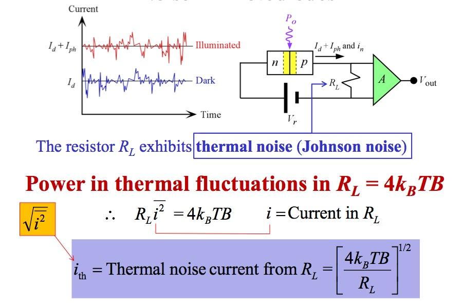
3 i(t) Noise in Photodiodes What is the RMS of fluctuations? Constant illumination Noise current = Total RMS current fluctuations The dark current has shot noise or fluctuations about I d, i n-dark = (2eI d B) 1/2 B = Bandwidth Quantum noise is due to the photon nature of light and its effects are the same as shot noise. Photocurrent has quantum noise or shot noise i n-quantum = (2eI ph B) 1/2
4 Noise in Photodiodes Total shot noise current, i n i 2 n = i 2 + i 2 n dark n quantum i n = [2e(I d + I ph )B] 1/2 We can conceptually view the photodetector current as I d + I ph + i n This flows through a load resistor R L and voltage across R L is amplified by A to give V out The noise voltage (RMS) due to shot noise in PD = i n R L A
5 Noise in Photodiodes Total current flowing into R L has three components: I d = Dark current. In principle, we can subtract this or block it with a capacitor if I ph is an ac (transient) signal. I ph = Photocurrent. This is the signal. We need this. It could be a steady or varying (ac or transient) signal. i n = Total shot noise. Due to shot noise from I d and I ph. We cannot eliminate this.
6 Noise in Photodiodes
7 Noise in PD abd R L Power in shot noise in PD = i n2 R L = [2e(I d + I ph )B]R L Power in thermal fluctuations in R L = 4k B TB Important Note: Total noise is always found by first summing the average powers involved in individual fluctuations e.g. power in shot noise + power in thermal noise Noise in the amplifier A must also be included See advanced textbooks
8 Signal to Noise Ratio SNR = Signal Power Noise Power SNR = i 2 n R L I 2 ph R L + 4k B TB = [ 2e( I + I ) B] d I ph 2 ph + 4kBTB R L Important Note: Total noise is always found by first summing the average powers involved in individual fluctuations e.g. power in shot noise + power in thermal noise
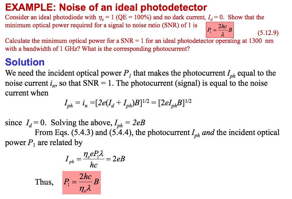
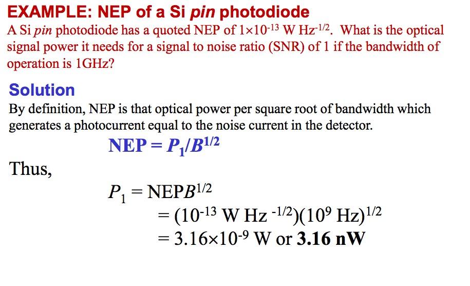
9 Noise Equivalent Power Definition NEP = Input power forsnr =1 Bandwidth = P 1 B 1/2 NEP is defined as the required optical input power to achieve a SNR of 1 within a bandwidth of 1 Hz NEP = P 1 B = 1 1/2 R 2e(I d + I ph ) 1/2 Units for NEP are W Hz 1/2
10 Noise Equivalent Power Definition NEP = Input power forsnr =1 Bandwidth = P 1 B 1/2 NEP is defined as the required optical input power to achieve a SNR of 1 within a bandwidth of 1 Hz NEP = P 1 B = 1 1/2 R 2e(I d + I ph ) 1/2 Units for NEP are W Hz 1/2 Detectivit y = 1 NEP D * = 1/ 2 A NEP Specific detectivity D* cm Hz -1/2 W -1, or Jones
11 NEP and Dark Current
12
13
14
15
16
17

18
19 EXAMPLE: SNR of a receiver Solution (continued) Shot noise current from the detector = [2e(I d + I ph )B] 1/2 = na = 1.29 na Thus, the noise contribution from R L is greater than that from the photodiode. The SNR is SNR Thermal Noise = 4k B TB R L 9 2 (5 10 A) = 9 2 ( A) + ( = 15.0 Generally SNR is quoted in decibels. We need 10log(SNR), or 10log(15.0) i.e., 11.8 db. Clearly, the load resistance has a dramatic effect on the overall noise performance. 1/2 9 A) 2
20 Linearly Polarized Light A linearly polarized wave has its electric field oscillations defined along a line perpendicular to the direction of propagation, z. The field vector E and z define a plane of polarization. The E-field oscillations are contained in the plane of polarization. A linearly polarized light at any instant can be represented by the superposition of two fields E x and E y with the right magnitude and phase

21 Circularly Polarized Light A right circularly polarized light. The field vector E is always at right angles to z, rotates clockwise around z with time, and traces out a full circle over one wavelength of distance propagated.
 is left circularly polarized light (as seen when the wave directly approaches a")
22 The Phase Difference Examples of linearly, (a) and (b), and circularly polarized light (c) and (d); (c) is right circularly and (d) is left circularly polarized light (as seen when the wave directly approaches a viewer)
23 Elliptically Polarized Light
24 Polarizers A polarizer allows field oscillations along a particular direction transmission axis to pass through Transmission axis (TA) The wire grid-acts as a polarizer There are many types of polarizers
 with a transmission axis TA 2 at an angle θ to TA 1.")
25 Malus s Law I ( θ ) = I ( 0)cos 2 θ Randomly polarized light is incident on a Polarizer 1 with a transmission axis TA 1. Emerging light from Polarizer 1 is linearly polarized with E along TA 1. Light is incident on Polarizer 2 (analyzer) with a transmission axis TA 2 at an angle θ to TA 1. Detector measures the intensity of the incident light.
26 Optical Anisotropy A line viewed through a cubic sodium chloride (halite) crystal (optically isotropic) and a calcite crystal (optically anisotropic)


27 Optically Isotropic Materials Liquids, glasses and cubic crystals are optically anisotropic The refractive index is the same in all directions for all polarizations of the field Sodium chloride (halite) crystal
28 Many crystals are optically anisotropic This line is due to the extraordinary wave The calcite crystal has two refractive indices The crystal exhibits double refraction This line is due to the ordinary wave Photo by SK A calcite crystal

29 Uniaxial Birefringent Crsytal Images viewed through a calcite crystal have orthogonal polarizations. Two polaroid analyzers are placed with their transmission axes, along the long edges, at right angles to each other. The ordinary ray, undeflected, goes through the left polarizer whereas the extraordinary wave, deflected, goes through the right polarizer. The two waves therefore have orthogonal polarizations
30 Principal refractive indices of some optically isotropic and anisotropic crystals (near 589 nm, yellow Na-D line) Optically isotropic n = n o Glass (crown) Diamond Fluorite (CaF 2 ) Uniaxial - Positive n o n e Ice Quartz Rutile (TiO 2 ) Uniaxial - Negative n o n e Calcite (CaCO 3 ) Tourmaline Lithium niobate (LiNbO 3 ) Biaxial n 1 n 2 n 3 Mica (muscovite)
31 Optical Indicatrix LEFT: Fresnel's ellipsoid (for n 1 = n 2 < n 3 ; quartz) RIGHT: An EM wave propagating along OP at an angle q to the optic axis.

32 Optical Indicatrix n e 1 ( θ ) 2 = cos n 2 2 o θ + sin n 2 2 e θ

33 Wave Propagation in a Uniaxial Crystal E o = E o -wave and E e = E e -wave (a) Wave propagation along the optic axis. (b) Wave propagation normal to optic axis.
34 Power Flow in Extraordinary Wave (a) Wavevector surface cuts in the xz plane for o- and e-waves. (b) An extraordinary wave in an anisotropic crystal with a k e at an angle to the optic axis. The electric field is not normal to k e. The energy flow (group velocity) is along S e which is different than k e.

35 Calcite Rhomb An EM wave that is off the optic axis of a calcite crystal splits into two waves called ordinary and extraordinary waves. These waves have orthogonal polarizations and travel with different velocities. The o-wave has a polarization that is always perpendicular to the optical axis.
Chiroptical Spectroscopy
 Chiroptical Spectroscopy Theory and Applications in Organic Chemistry Lecture 2: Polarized light Masters Level Class (181 041) Mondays, 8.15-9.45 am, NC 02/99 Wednesdays, 10.15-11.45 am, NC 02/99 28 Electromagnetic
Chap. 2. Polarization of Optical Waves
 Chap. 2. Polarization of Optical Waves 2.1 Polarization States - Direction of the Electric Field Vector : r E = E xˆ + E yˆ E x x y ( ω t kz + ϕ ), E = E ( ωt kz + ϕ ) = E cos 0 x cos x y 0 y - Role :
Physics I Keystone Institute Technology & Management Unit-II
 Un-polarized light Ordinary light is a collection of wave trains emitted by atoms or group of atoms with coherent time no longer than 10-8 second. Each wave train has different orientation and phase of
Optics and Optical Design. Chapter 6: Polarization Optics. Lectures 11 13
 Optics and Optical Design Chapter 6: Polarization Optics Lectures 11 13 Cord Arnold / Anne L Huillier Polarization of Light Arbitrary wave vs. paraxial wave One component in x direction y x z Components
Optics and Optical Design. Chapter 6: Polarization Optics. Lectures 11-13
 Optics and Optical Design Chapter 6: Polarization Optics Lectures 11-13 Cord Arnold / Anne L Huillier Polarization of Light Arbitrary wave vs. paraxial wave One component in x-direction y x z Components
Wave Propagation in Uniaxial Media. Reflection and Transmission at Interfaces
 Lecture 5: Crystal Optics Outline 1 Homogeneous, Anisotropic Media 2 Crystals 3 Plane Waves in Anisotropic Media 4 Wave Propagation in Uniaxial Media 5 Reflection and Transmission at Interfaces Christoph
ECE 185 ELECTRO-OPTIC MODULATION OF LIGHT
 ECE 185 ELECTRO-OPTIC MODULATION OF LIGHT I. Objective: To study the Pockels electro-optic (EO) effect, and the property of light propagation in anisotropic medium, especially polarization-rotation effects.
Lecture 5: Polarization. Polarized Light in the Universe. Descriptions of Polarized Light. Polarizers. Retarders. Outline
 Lecture 5: Polarization Outline 1 Polarized Light in the Universe 2 Descriptions of Polarized Light 3 Polarizers 4 Retarders Christoph U. Keller, Leiden University, keller@strw.leidenuniv.nl ATI 2016,
Chap. 4. Electromagnetic Propagation in Anisotropic Media
 Chap. 4. Electromagnetic Propagation in Anisotropic Media - Optical properties depend on the direction of propagation and the polarization of the light. - Crystals such as calcite, quartz, KDP, and liquid
Optics, Optoelectronics and Photonics
 Optics, Optoelectronics and Photonics Engineering Principles and Applications Alan Billings Emeritus Professor, University of Western Australia New York London Toronto Sydney Tokyo Singapore v Contents
[D] indicates a Design Question
![[D] indicates a Design Question](/thumbs/77/76276479.jpg "[D] indicates a Design Question") EP421 Assignment 4: Polarization II: Applications of Optical Anisotropy use of the Jones Calculus (Handed Out: Friday 1 November 2013 Due Back: Friday 8 November 2013) 1. Optic Axis of Birefringent Crystals
EP421 Assignment 4: Polarization II: Applications of Optical Anisotropy use of the Jones Calculus (Handed Out: Friday 1 November 2013 Due Back: Friday 8 November 2013) 1. Optic Axis of Birefringent Crystals
Modern Optics Prof. Partha Roy Chaudhuri Department of Physics Indian Institute of Technology, Kharagpur
 Modern Optics Prof. Partha Roy Chaudhuri Department of Physics Indian Institute of Technology, Kharagpur Lecture 08 Wave propagation in anisotropic media Now, we will discuss the propagation of electromagnetic
Polarizers and Retarders
 Phys 531 Lecture 20 11 November 2004 Polarizers and Retarders Last time, discussed basics of polarization Linear, circular, elliptical states Describe by polarization vector ĵ Today: Describe elements
Waves & Oscillations
 Physics 42200 Waves & Oscillations Lecture 32 Polarization of Light Spring 2015 Semester Matthew Jones Types of Polarization Light propagating through different materials: One polarization component can
Lecture 4: Anisotropic Media. Dichroism. Optical Activity. Faraday Effect in Transparent Media. Stress Birefringence. Form Birefringence
 Lecture 4: Anisotropic Media Outline Dichroism Optical Activity 3 Faraday Effect in Transparent Media 4 Stress Birefringence 5 Form Birefringence 6 Electro-Optics Dichroism some materials exhibit different
OPTI510R: Photonics. Khanh Kieu College of Optical Sciences, University of Arizona Meinel building R.626
 OPTI510R: Photonics Khanh Kieu College of Optical Sciences, University of Arizona kkieu@optics.arizona.edu Meinel building R.626 Announcements Homework #6 is assigned, due May 1 st Final exam May 8, 10:30-12:30pm
Polarization of Light and Birefringence of Materials
 Polarization of Light and Birefringence of Materials Ajit Balagopal (Team Members Karunanand Ogirala, Hui Shen) ECE 614- PHOTONIC INFORMATION PROCESSING LABORATORY Abstract-- In this project, we study
Chap. 5. Jones Calculus and Its Application to Birefringent Optical Systems
 Chap. 5. Jones Calculus and Its Application to Birefringent Optical Systems - The overall optical transmission through many optical components such as polarizers, EO modulators, filters, retardation plates.
Lab #13: Polarization
 Lab #13: Polarization Introduction In this experiment we will investigate various properties associated with polarized light. We will study both its generation and application. Real world applications
Light for which the orientation of the electric field is constant although its magnitude and sign vary in time.
 L e c t u r e 8 1 Polarization Polarized light Light for which the orientation of the electric field is constant although its magnitude and sign vary in time. Imagine two harmonic, linearly polarized light
Modulators. Tuesday, 11/14/2006 Physics 158 Peter Beyersdorf. Document info 17. 1
 Modulators Tuesday, 11/14/2006 Physics 158 Peter Beyersdorf Document info 17. 1 Class Outline Birefringence Optical Activity Faraday Rotation Optical Modulators Electrooptic Modulators Accoustooptic Modulators
GY 302: Crystallography & Mineralogy
 UNIVERSITY OF SOUTH ALABAMA GY 302: Crystallography & Mineralogy Lecture 7a: Optical Mineralogy (two day lecture) Instructor: Dr. Douglas Haywick This Week s Agenda 1. Properties of light 2. Minerals and
Lecture 4: Polarisation of light, introduction
 Lecture 4: Polarisation of light, introduction Lecture aims to explain: 1. Light as a transverse electro-magnetic wave 2. Importance of polarisation of light 3. Linearly polarised light 4. Natural light
16. More About Polarization
 16. More About Polarization Polarization control Wave plates Circular polarizers Reflection & polarization Scattering & polarization Birefringent materials have more than one refractive index A special
POLARISATION. We have not really discussed the direction of the Electric field other that that it is perpendicular to the direction of motion.
 POLARISATION Light is a transverse electromagnetic wave. We have not really discussed the direction of the Electric field other that that it is perpendicular to the direction of motion. If the E field
Introduction to Polarization
 Phone: Ext 659, E-mail: hcchui@mail.ncku.edu.tw Fall/007 Introduction to Polarization Text Book: A Yariv and P Yeh, Photonics, Oxford (007) 1.6 Polarization States and Representations (Stokes Parameters
4. Circular Dichroism - Spectroscopy
 4. Circular Dichroism - Spectroscopy The optical rotatory dispersion (ORD) and the circular dichroism (CD) are special variations of absorption spectroscopy in the UV and VIS region of the spectrum. The
NAWAB SHAH ALAM KHAN COLLEGE OF ENGINEERING & TECHNOLOGY UNIT II-a POLARISATION
 NAWAB SHAH ALAM KHAN COLLEGE OF ENGINEERING & TECHNOLOGY UNIT II-a 1 POLARISATION SYLLABUS :Polarization: Introduction, Malus s law, double refraction, Nicol prism, Quarter wave and half wave plates. 1.
What is polarization?
 Polarimetry What is polarization? Linear polarization refers to photons with their electric vectors always aligned in the same direction (below). Circular polarization is when the tip of the electric vector
Optical Mineralogy. Optical Mineralogy. Use of the petrographic microscope
 Optical Mineralogy Optical Mineralogy Use of the petrographic microscope John Winter, Whitman College with some slides Jane Selverstone, University of New Mexico, 2003 Why use the microscope?? Identify
Brewster Angle and Total Internal Reflection
 Lecture 4: Polarization Outline 1 Polarized Light in the Universe 2 Brewster Angle and Total Internal Reflection 3 Descriptions of Polarized Light 4 Polarizers 5 Retarders Christoph U. Keller, Utrecht
Chapter 1 - The Nature of Light
 David J. Starling Penn State Hazleton PHYS 214 Electromagnetic radiation comes in many forms, differing only in wavelength, frequency or energy. Electromagnetic radiation comes in many forms, differing
Polarization Mode Dispersion
 Unit-7: Polarization Mode Dispersion https://sites.google.com/a/faculty.muet.edu.pk/abdullatif Department of Telecommunication, MUET UET Jamshoro 1 Goos Hänchen Shift The Goos-Hänchen effect is a phenomenon
POLARIZATION OF LIGHT
 POLARIZATION OF LIGHT OVERALL GOALS The Polarization of Light lab strongly emphasizes connecting mathematical formalism with measurable results. It is not your job to understand every aspect of the theory,
Phys 2310 Mon. Oct. 30, 2017 Today s Topics. Begin Modern Optics Ch. 2: The Nature of Polarized Light Reading for Next Time
 Phys 3 Mon. Oct. 3, 7 Today s Topics Begin Modern Optics Ch. : The Nature of Polarized Light Reading for Next Time By Wed.: Reading this Week Begin Ch. of Modern Optics (. 8.) Nature of Polarized Light,
Photosynthesis & Solar Power Harvesting
 Lecture 23 Semiconductor Detectors - Photodetectors Principle of the pn junction photodiode Absorption coefficient and photodiode materials Properties of semiconductor detectors The pin photodiodes Avalanche
LC circuit: Energy stored. This lecture reviews some but not all of the material that will be on the final exam that covers in Chapters
 Disclaimer: Chapter 29 Alternating-Current Circuits (1) This lecture reviews some but not all of the material that will be on the final exam that covers in Chapters 29-33. LC circuit: Energy stored LC
Experiment 5 Polarization and Modulation of Light
 1. Objective Experiment 5 Polarization and Modulation of Light Understanding the definition of polarized and un-polarized light. Understanding polarizer and analzer definition, Maluse s law. Retarding
Summary of Fourier Optics
 Summary of Fourier Optics Diffraction of the paraxial wave is described by Fresnel diffraction integral, u(x, y, z) = j λz dx 0 dy 0 u 0 (x 0, y 0 )e j(k/2z)[(x x 0) 2 +(y y 0 ) 2 )], Fraunhofer diffraction
Brewster Angle and Total Internal Reflection
 Lecture 5: Polarization Outline 1 Polarized Light in the Universe 2 Brewster Angle and Total Internal Reflection 3 Descriptions of Polarized Light 4 Polarizers 5 Retarders Christoph U. Keller, Leiden University,
Lab 8 - POLARIZATION
 137 Name Date Partners Lab 8 - POLARIZATION OBJECTIVES To study the general phenomena of electromagnetic wave polarization To investigate linearly polarized microwaves To investigate linearly polarized
Comunicações Ópticas Noise in photodetectors MIEEC EEC038. Henrique Salgado Receiver operation
 Comunicações Ópticas Noise in photodetectors 2007-2008 MIEEC EEC038 Henrique Salgado hsalgado@fe.up.pt Receiver operation Noise plays a fundamental role in design of an optical receiver Optical data link
Lab 8 - Polarization
 Lab 8 Polarization L8-1 Name Date Partners Lab 8 - Polarization OBJECTIVES To study the general phenomena of electromagnetic wave polarization To investigate linearly polarized microwaves To investigate
OPTI510R: Photonics. Khanh Kieu College of Optical Sciences, University of Arizona Meinel building R.626
 OPTI510R: Photonics Khanh Kieu College of Optical Sciences, University of Arizona kkieu@optics.arizona.edu Meinel building R.626 Important announcements Homework #2 is due Feb. 12 Mid-term exam Feb 28
Optical Mineralogy in a Nutshell
 Optical Mineralogy in a Nutshell Use of the petrographic microscope Slides borrowed/adapted from Jane Selverstone (University of New Mexico) and John Winter (Whitman College) Why use the petrographic microscope?
Lecture 8: Polarimetry 2. Polarizers and Retarders. Polarimeters. Scattering Polarization. Zeeman Effect. Outline
 Lecture 8: Polarimetry 2 Outline 1 Polarizers and Retarders 2 Polarimeters 3 Scattering Polarization 4 Zeeman Effect Christoph U. Keller, Utrecht University, C.U.Keller@uu.nl Observational Astrophysics
Physics 214 Course Overview
 Physics 214 Course Overview Lecturer: Mike Kagan Course topics Electromagnetic waves Optics Thin lenses Interference Diffraction Relativity Photons Matter waves Black Holes EM waves Intensity Polarization
polarisation of Light
 Basic concepts to understand polarisation of Light Polarization of Light Nature of light: light waves are transverse in nature i. e. the waves propagates in a direction perpendicular to the direction of
 Name : Roll No. :.. Invigilator s Signature :.. CS/B.Tech/SEM-2/PH-201/2010 2010 ENGINEERING PHYSICS Time Allotted : 3 Hours Full Marks : 70 The figures in the margin indicate full marks. Candidates are
Lab 11 - Polarization
 181 Name Date Partners Lab 11 - Polarization OBJECTIVES To study the general phenomena of electromagnetic wave polarization To investigate linearly polarized microwaves To investigate linearly polarized
Waves & Oscillations
 Physics 42200 Waves & Oscillations Lecture 32 Electromagnetic Waves Spring 2016 Semester Matthew Jones Electromagnetism Geometric optics overlooks the wave nature of light. Light inconsistent with longitudinal
Chapter 7: Optical Properties of Solids. Interaction of light with atoms. Insert Fig Allowed and forbidden electronic transitions
 Chapter 7: Optical Properties of Solids Interaction of light with atoms Insert Fig. 8.1 Allowed and forbidden electronic transitions 1 Insert Fig. 8.3 or equivalent Ti 3+ absorption: e g t 2g 2 Ruby Laser
Light Waves and Polarization
 Light Waves and Polarization Xavier Fernando Ryerson Communications Lab http://www.ee.ryerson.ca/~fernando The Nature of Light There are three theories explain the nature of light: Quantum Theory Light
Chapter 6. Polarization Optics
 Chapter 6. Polarization Optics 6.1 Polarization of light 6. Reflection and refraction 6.3 Optics of anisotropic media 6.4 Optical activity and magneto-optics 6.5 Optics of liquid crystals 6.6 Polarization
POLARIZATION FUNDAMENTAL OPTICS POLARIZATION STATES 1. CARTESIAN REPRESENTATION 2. CIRCULAR REPRESENTATION. Polarization. marketplace.idexop.
 POLARIZATION POLARIZATION STATS Four numbers are required to describe a single plane wave Fourier component traveling in the + z direction. These can be thought of as the amplitude and phase shift of the
Lab 11 - Polarization
 177 Name Date Partners OBJECTIVES Lab 11 - Polarization To study the general phenomena of electromagnetic polarization To see that microwaves are polarized To observe how light waves are linearly polarized
Waves & Oscillations
 Physics 42200 Waves & Oscillations Lecture 25 Propagation of Light Spring 2013 Semester Matthew Jones Midterm Exam: Date: Wednesday, March 6 th Time: 8:00 10:00 pm Room: PHYS 203 Material: French, chapters
Purpose: To convert the received optical signal into an electrical lsignal.
 OPTICAL DETECTORS Optical Detectors Purpose: To convert the received optical signal into an electrical lsignal. Requirements For Detector HIGH SENSITIVITY (at operating wave lengths) at normal op. temp
Polarized Light. Nikki Truss. Abstract:
 Polarized Light Nikki Truss 9369481 Abstract: In this experiment, the properties of linearly polarised light were examined. Malus Law was verified using the apparatus shown in Fig. 1. Reflectance of s-polarised
Electromagnetic Properties of Materials Part 2
 ECE 5322 21 st Century Electromagnetics Instructor: Office: Phone: E Mail: Dr. Raymond C. Rumpf A 337 (915) 747 6958 rcrumpf@utep.edu Lecture #3 Electromagnetic Properties of Materials Part 2 Nonlinear
Chapter 33: ELECTROMAGNETIC WAVES 559
 Chapter 33: ELECTROMAGNETIC WAVES 1 Select the correct statement: A ultraviolet light has a longer wavelength than infrared B blue light has a higher frequency than x rays C radio waves have higher frequency
Jones calculus for optical system
 2/14/17 Electromagnetic Processes In Dispersive Media, Lecture 6 1 Jones calculus for optical system T. Johnson Key concepts in the course so far What is meant by an electro-magnetic response? What characterises
MP5: Soft Matter: Physics of Liquid Crystals
 MP5: Soft Matter: Physics of Liquid Crystals 1 Objective In this experiment a liquid crystal display (LCD) is built and its functionality is tested. The light transmission as function of the applied voltage
Polarimetry in the E-ELT era. Polarized Light in the Universe. Descriptions of Polarized Light. Polarizers. Retarders. Fundamentals of Polarized Light
 Polarimetry in the E-ELT era Fundamentals of Polarized Light 1 Polarized Light in the Universe 2 Descriptions of Polarized Light 3 Polarizers 4 Retarders Christoph U. Keller, Leiden University, keller@strw.leidenuniv.nl
4: birefringence and phase matching
 /3/7 4: birefringence and phase matching Polarization states in EM Linear anisotropic response χ () tensor and its symmetry properties Working with the index ellipsoid: angle tuning Phase matching in crystals
Photonic Communications Engineering Lecture. Dr. Demetris Geddis Department of Engineering Norfolk State University
 Photonic Communications Engineering Lecture Dr. Demetris Geddis Department of Engineering Norfolk State University Light Detectors How does this detector work? Image from visionweb.com Responds to range
Quarter wave plates and Jones calculus for optical system
 2/11/16 Electromagnetic Processes In Dispersive Media, Lecture 6 1 Quarter wave plates and Jones calculus for optical system T. Johnson 2/11/16 Electromagnetic Processes In Dispersive Media, Lecture 6
Lect. 10: Photodetectors
 Photodetection: Absorption => Current Generation h Currents Materials for photodetection: E g < h Various methods for generating currents with photo-generated carriers: photoconductors, photodiodes, avalanche
Topic 4: Waves 4.3 Wave characteristics
 Guidance: Students will be expected to calculate the resultant of two waves or pulses both graphically and algebraically Methods of polarization will be restricted to the use of polarizing filters and
EM Waves. From previous Lecture. This Lecture More on EM waves EM spectrum Polarization. Displacement currents Maxwell s equations EM Waves
 EM Waves This Lecture More on EM waves EM spectrum Polarization From previous Lecture Displacement currents Maxwell s equations EM Waves 1 Reminders on waves Traveling waves on a string along x obey the
POLARIZATION AND BIREFRINGENCE
 UNIT 3 POLARIZATION AND BIREFRINGENCE Name Lab Partner(s) Date Lab Section # TA signature Be sure to have your TA check your lab work and sign this sheet before you leave. Save it until the end of the
LEC E T C U T R U E R E 17 -Photodetectors
 LECTURE 17 -Photodetectors Topics to be covered Photodetectors PIN photodiode Avalanche Photodiode Photodetectors Principle of the p-n junction Photodiode A generic photodiode. Photodetectors Principle
Experiment and Simulation Study on A New Structure of Full Optical Fiber Current Sensor
 2017 2nd International Conference on Computational Modeling, Simulation and Applied Mathematics (CMSAM 2017) ISBN: 978-1-60595-499-8 Experiment and Simulation Study on A New Structure of Full Optical Fiber
Objectives. Faraday Rotation. Introduction. component. polarizers are at 0 with respect to. reduced to
 Faraday Rotation Objectives o To verify Malus law for two polarizers o To study the effect known as Faraday Rotation Introduction Light consists of oscillating electric and magnetic fields. Light is polarized
LECTURE 23: LIGHT. Propagation of Light Huygen s Principle
 LECTURE 23: LIGHT Propagation of Light Reflection & Refraction Internal Reflection Propagation of Light Huygen s Principle Each point on a primary wavefront serves as the source of spherical secondary
Lecture 21 Reminder/Introduction to Wave Optics
 Lecture 1 Reminder/Introduction to Wave Optics Program: 1. Maxwell s Equations.. Magnetic induction and electric displacement. 3. Origins of the electric permittivity and magnetic permeability. 4. Wave
4. The interaction of light with matter
 4. The interaction of light with matter The propagation of light through chemical materials is described by a wave equation similar to the one that describes light travel in a vacuum (free space). Again,
September 14, Monday 4. Tools for Solar Observations-II
 September 14, Monday 4. Tools for Solar Observations-II Spectrographs. Measurements of the line shift. Spectrograph Most solar spectrographs use reflection gratings. a(sinα+sinβ) grating constant Blazed
MOCK CET PHYSICS PAPER 1
 MOCK CET PHYSICS PAPER 1 1. Rotational kinetic energy of a body is given by the equation 2 2 where I is moment of inertia and ω angular velocity of the body. The dimensional formula of I using the above
PHYS 450 Spring semester Lecture 13: Polarized Light. Ron Reifenberger Birck Nanotechnology Center Purdue University. Historical Timeline
 PHYS 450 Spring semester 2017 Lecture 13: Polarized Light Ron Reifenberger Birck Nanotechnology Center Purdue University Lecture 13 1 Historical Timeline 1669 Bartholinus describes image doubling properties
LECTURE 23: LIGHT. Propagation of Light Huygen s Principle
 LECTURE 23: LIGHT Propagation of Light Reflection & Refraction Internal Reflection Propagation of Light Huygen s Principle Each point on a primary wavefront serves as the source of spherical secondary
PH 222-2C Fall Electromagnetic Waves Lectures Chapter 33 (Halliday/Resnick/Walker, Fundamentals of Physics 8 th edition)
") PH 222-2C Fall 2012 Electromagnetic Waves Lectures 21-22 Chapter 33 (Halliday/Resnick/Walker, Fundamentals of Physics 8 th edition) 1 Chapter 33 Electromagnetic Waves Today s information age is based almost
PH 222-2C Fall 2012 Electromagnetic Waves Lectures 21-22 Chapter 33 (Halliday/Resnick/Walker, Fundamentals of Physics 8 th edition) 1 Chapter 33 Electromagnetic Waves Today s information age is based almost
Electromagnetic Wave Propagation Lecture 8: Propagation in birefringent media
 Electromagnetic Wave Propagation Lecture 8: Propagation in birefringent media Daniel Sjöberg Department of Electrical and Information Technology September 27, 2012 Outline 1 Introduction 2 Maxwell s equations
Photodetectors Read: Kasip, Chapter 5 Yariv, Chapter 11 Class Handout. ECE 162C Lecture #13 Prof. John Bowers
 Photodetectors Read: Kasip, Chapter 5 Yariv, Chapter 11 Class Handout ECE 162C Lecture #13 Prof. John Bowers Definitions Quantum efficiency η: Ratio of the number of electrons collected to the number of
Semiconductor Optoelectronics Prof. M. R. Shenoy Department of Physics Indian Institute of Technology, Delhi
 Semiconductor Optoelectronics Prof. M. R. Shenoy Department of Physics Indian Institute of Technology, Delhi Lecture - 1 Context and Scope of the Course (Refer Slide Time: 00:44) Welcome to this course
OPTI 501, Electromagnetic Waves (3)
") OPTI 501, Electromagnetic Waves (3) Vector fields, Maxwell s equations, electromagnetic field energy, wave equations, free-space solutions, box modes, Fresnel equations, scalar and vector potentials, gauge
OPTI 501, Electromagnetic Waves (3) Vector fields, Maxwell s equations, electromagnetic field energy, wave equations, free-space solutions, box modes, Fresnel equations, scalar and vector potentials, gauge
Last Time. GY 302: Crystallography & Mineralogy. Polymorphs & Polymorphism. Other Crystal Structures. Other Crystal Structures. This Week s Agenda
 UNIVERSITY OF SOUTH ALABAMA Last Time GY 302: Crystallography & Mineralogy 1. Polymorphs and Polymorphism 2. Pseudomorphs and other definitions 3. Crystal Habit Lecture 7: Optical Mineralogy (two day lecture?)
IO.5 Elliptically Polarized Light
 1. Purpose: IO.5 Elliptically Polarized Light Analyze elliptically polarized light; determine the orientation of the vibration ellipse and the ratio of its semi-axes. 2. Apparatus: Gaertner Scientific
Optical Parametric Generation
 x (2) Parametric Processes 27 Optical Parametric Generation Spontaneous parametric down-conversion occurs when a pump photon at v P spontaneously splits into two photons called the signal at v S, and the
Class XII_All India_Physics_Set-2
 Class XII_All India_Physics_Set- 17. Draw V I characteristics of a p-n junction diode. Answer the following questions, giving reasons: (i) Why is the current under reverse bias almost independent of the
Testing stress birefringence of an optical window. Chiayu Ai and. James C. Wyant. WYKO Corp., 2650 E. Elvira Road, Tucson, AZ ABSTRACT
 Testing stress birefringence of an optical window Chiayu Ai and James C. Wyant WYKO Corp., 2650 E. Elvira Road, Tucson, AZ 85706 ABSTRACT This paper describes a method to measure the birefringence of an
Electromagnetic Waves. Chapter 33 (Halliday/Resnick/Walker, Fundamentals of Physics 8 th edition)
") PH 222-3A Spring 2007 Electromagnetic Waves Lecture 22 Chapter 33 (Halliday/Resnick/Walker, Fundamentals of Physics 8 th edition) 1 Chapter 33 Electromagnetic Waves Today s information age is based almost
PH 222-3A Spring 2007 Electromagnetic Waves Lecture 22 Chapter 33 (Halliday/Resnick/Walker, Fundamentals of Physics 8 th edition) 1 Chapter 33 Electromagnetic Waves Today s information age is based almost
Phase Sensitive Faraday Rotation in. and various Diamagnetic liquid Samples
 Phase Sensitive Faraday Rotation in TERBIUM GALLIUM GARNET crystal and various Diamagnetic liquid Samples Supervisor: Dr. Saadat Anwar Siddiqi Co-Supervisor: Dr. Muhammad Sabieh Anwar Presented by: Aysha
Chapter 4. Photodetectors
 Chapter 4 Photodetectors Types of photodetectors: Photoconductos Photovoltaic Photodiodes Avalanche photodiodes (APDs) Resonant-cavity photodiodes MSM detectors In telecom we mainly use PINs and APDs.
Experimental competition. Thursday, 17 July /9 Experiment. To see invisible! (20 points)
") Experimental competition. Thursday, 17 July 2014 1/9 Experiment. To see invisible! (20 points) Introduction Many substances exhibit optical anisotropy resulting in that the refractive index turns out dependent
Experimental competition. Thursday, 17 July 2014 1/9 Experiment. To see invisible! (20 points) Introduction Many substances exhibit optical anisotropy resulting in that the refractive index turns out dependent
Chapter 33. Electromagnetic Waves
 Chapter 33 Electromagnetic Waves Today s information age is based almost entirely on the physics of electromagnetic waves. The connection between electric and magnetic fields to produce light is own of
DEGREE OF POLARIZATION VS. POINCARÉ SPHERE COVERAGE - WHICH IS NECESSARY TO MEASURE PDL ACCURATELY?
 DEGREE OF POLARIZATION VS. POINCARÉ SPHERE COVERAGE - WHICH IS NECESSARY TO MEASURE PDL ACCURATELY? DEGREE OF POLARIZATION VS. POINCARE SPHERE COVERAGE - WHICH IS NECESSARY TO MEASURE PDL ACCURATELY? Introduction
Lecture 3 : Electrooptic effect, optical activity and basics of interference colors with wave plates
 Lecture 3 : Electrooptic effect, optical activity and basics of interference colors with wave plates NW optique physique II 1 Electrooptic effect Electrooptic effect: example of a KDP Pockels cell Liquid
FIRST YEAR PHYSICS. Unit 4: Light II
 FIRST YEAR PHYSICS Unit 4: Light II Contents PHASORS...3 RESOLUTION OF OPTICAL INSTRUMENTS...5 Rayleigh s criterion... 7 MORE ON DIFFRACTION...11 Multiple slits:... 11 Diffraction gratings... 14 X-RAY