Force Based Design Fundamentals. Ian Buckle Director Center for Civil Engineering Earthquake Research University of Nevada, Reno
|
|
|
- Kory Dennis
- 5 years ago
- Views:
Transcription
1 Force Based Design Fundamentals Ian Buckle Director Center for Civil Engineering Earthquake Research University of Nevada, Reno
2 Learning Outcomes Explain difference between elastic forces, actual forces and Modified Design Forces Define a plastic hinge Explain Capacity Protection ti Philosophyh Describe the Component Capacity/Demand Retrofit Method (Method C) Describe how P-Δ effects are considered in design
3 Late eral For rce Force vs. Displacement F EQ Elastic Response F EQ Δ EQ Δ EQ Displacement - Δ Elastic Analysis & Response
4 Force vs. Displacement For moderate-large earthquakes, F EQ is a very large force (can be > structure weight) and it is uneconomical to design an ordinary bridge to resist this force elastically Inelastic behavior (damage) is therefore accepted, provided it does not cause collapse is ductile in nature (not brittle), and occurs in designated components (members) Exceptions are made for special structures where the higher cost of elastic (or almost elastic) behavior can be justified
5 Force vs. Displacement La ateral Fo orce F mechanism First-Order Rigid- Plastic Analysis F mechanism F mechanism Plastic hinge Displacement - Δ Plastic hinge First Order Rigid-Plastic analysis assumes all deformations take place at discrete regions, called plastic hinges, and that a sufficient number of plastic hinges have formed to form a mechanism in the pier/bent. First-Order Rigid Plastic Pier Response
6 Force vs. Displacement l Force Latera Fir rst-order Rig gid-plastic Re esponse Elastic Response Idealized Elasto-Plastic Response Displacement - Δ Idealized Elasto-Plastic Response
7 Force vs. Displacement La ateral Fo orce F max 1 2 Actual Response F EQ 3 4 Plastic Hinge Δ EQ Displacement - Δ Actual Response Milestones 1 - Pseudo-yield Point 2 Maximum Plastic Deformations 3 Onset of Collapse 4 - Collapse
8 Force vs. Displacement Elastic Response Δ EQ l Force F EQ Actual Response F EQ Latera Δ EQ Displacement - Δ Elastic vs. Actual Response
9 Force vs. Displacement l Force Latera Fir rst-order Rig gid-plastic Re esponse Elastic Response Idealized Elasto-Plastic Response Displacement - Δ At Actual lresponse Idealized Elasto-Plastic Response
10 Force vs. Displacement La ateral Fo orce Elastic Analysis Displacement - Δ First-Order Elastic-Plastic Second-Order Elastic-Plastic (slender column response shown- requirements are in place to limit this type of behavior) Elastic Analysis conducted using to linear methods First-order elasto-plastic behavior includes reduced pier/bent stiffness and strength with progressive plastic hinge formation. Second-order elasto-plastic behavior traces formation of plastic hinges and includes geometric non-linearities (e.g. P-Δ) Pier Response with Higher Order Effects
11 Force vs. Displacement Member strengths: Nominal strength, S n Design strength, S d = φ S n where φ is the strength th reduction factor <1.0 (see AASHTO LRFD Specifications) [Expected strength, S e = φ e S n where, in absence of mill certificates, φ e =1.2 for steel and 1.3 for concrete members] Over-strength, S o = φ o S n where φ o is the over-strength factor >1.0 ( )
12 Force vs. Displacement F elastic Latera al Force F overstrength F mechanism Design for lesser of F elastic or F overstrength Overstrength Factor Displacement - Δ F overstrength = φ o F mechanism where φ o = over-strength factor overstrength o mechanism o Over-strength Forces
13 Force vs. Displacement Later ral Forc ce μ = Δ max Δ yield Δ yield Δ max Displacement - Δ Displacement Ductility Factor - μ
14 Force vs. Displacement To calculate Δ max Nonlinear time history analysis using software such as SAP2000, SEISAB-NL, ADINA, ABAQUS Elastic analysis using either ULM, SMSA, MMSA, TH to find maximum elastic displacement Δ EQ and then assume either: Equal displacements, i.e. Δ max = Δ EQ or: Equal work done during elasto-plastic response as during elastic response, and solve for Δ max
15 Force vs. Displacement F elastic Define R = F elastic F mechanism (Response Modification Factor) rce Lat teral Fo F mechanism Δ yield F elastic R Δ max = Δ EQ Displacement - Δ Then: Δ max = Δ EQ and: μ = Δ max = R Δ yield (Displacement Ductility Factor) Relationship between ductility and R Equal Displacement Assumption
16 Force vs. Displacement F elastic Define R = F elastic F mechanism (Response Modification Factor) rce Lat teral Fo F mechanism Δ yield F elastic R Δ max = Δ EQ Displacement - Δ Then: Δ max = Δ EQ and: μ = Δ max = R Δ yield (Displacement Ductility Factor) Relationship between ductility and R Equal Displacement Assumption
17 Force vs. Displacement Define R = F elastic F mechanism (Response Modification Factor) Force Lateral F elastic F mechanism F elastic R Then: Δ max = (R Δ EQ + Δ yield ) / 2 and: μ = Δ max (R 2 + 1) / 2 Δ yield (Displacement Ductility Factor) Δ yield Δ EQ Δ max Displacement - Δ Relationship between ductility and R Equal Work Done Assumption
18 Force vs. Displacement Define R = F elastic F mechanism (Response Modification Factor) Force Lateral F elastic F mechanism F elastic R Then: Δ max = (R Δ EQ + Δ yield ) / 2 and: μ = Δ max (R 2 + 1) / 2 Δ yield (Displacement Ductility Factor) Δ yield Δ EQ Δ max Displacement - Δ Relationship between ductility and R Equal Work Done Assumption
19 Force vs. Displacement μ = R = 1 Late eral For rce μ = Δ max R Δ yield μ = R = 2 μ = R = 3 μ = R = 5 In ncreasin ng Ducti ility Δ yield Displacement - Δ Δ max Substructure Type Strength and Ductility Relationship
20 Force vs. Displacement Late eral For rce μ = Δ max R Δ yield Δ yield Displacement - Δ Δ max μ = R = 1 μ = R = 2 μ = R = 3 μ = R = 5 In ncreasin ng Ducti ility Substructure Type Strength and Ductility Relationship xibility Δ EQ sing flex higher Δ Increas period, NOTE: longer
21 Force vs. Displacement Late eral For rce μ = Δ max R Δ yield Δ yield Displacement - Δ Δ max μ = R = 1 μ = R = 2 μ = R = 3 μ = R = 5 In ncreasin ng Ducti ility Substructure Type Strength and Ductility Relationship xibility Δ EQ sing flex higher Δ Increas period, NOTE: longer
22 Force vs. Displacement Latera al Force F elastic F overstrength F mechanism = F design F R F elastic Effec ct of R Axial Force (Pn, M n ) ΦP n ΦM n ign P,M des (P n, M n ) w/ Over-strength PM P,M elastic Displacement - Δ Moment F elastic & P,M elastic force effect generated from Extreme Event 1 load combination Elastic vs. Modified Design vs. Over-strength Forces
23 Capacity Protection The principle of Capacity Protection Design is that yielding in one component (or member) will cap (or limit) the forces and moments in an adjacent component (member). i.e. reaching the elastic capacity (yield) of one member protects adjacent members from excessive forces
24 Capacity Protection Bridge Geometry F, Δ A B C D h 1 h 2 E F
25 Capacity Protection Bridge Geometry Bending Moment Diagram F, Δ A B C D F, Δ M p 2 4 h 1 h 2 M M p 1 V EB E F Two plastic hinges in BE, 3 V FC V EB max = 2 M p / h 1
26 Capacity Protection Bridge Geometry Bending Moment Diagram F, Δ A B C D F, Δ M p 2 4 h 1 h 2 M M p 1 V EB F 2 E 3 4 F Two plastic hinges in BE, V EB max = 2 M p / h 1 3 V FC 1 V FC F = V EB + V EB V FC Δ
27 Capacity Protection Bridge Geometry Bending Moment Diagram F, Δ A B C D F, Δ M p 2 4 h 1 h 2 M M p 1 V EB F E Two plastic hinges in EB, 3 V FC F V EB max =2M p /h Maximum shear and moment in V FC foundation at E is limited by yielding F = V EB + in EB, i.e. the foundation is capacity V EB V FC protected by column yield Δ
28 Capacity Protection Bridge Geometry Bending Moment Diagram F, Δ A B C D F, Δ M p 2 4 h 1 h 2 M M p 1 V EB E Two plastic hinges in EB, 3 V FC F F V EB max =2M p /h NOTE: For design M V p = φ M n, but to 1 FC calculate max. value of V EB, should F = V EB + use the overstrength moment, V EB V FC i.e. M p =φ o M n where (φ o > 1) Δ
29 Seismic Retrofit Process Three step process: Screening and Prioritization Detailed Evaluation Retrofit strategies, approaches and measures
30 Evaluation Methods FHWA Manual describes 5 basic methods for evaluation Methods vary in rigor from no-analysis analysis to nonlinear dynamic time history analysis Selection / application depends d on the Seismic Retrofit Category A D for the bid bridge (seismic i hazard and performance required), and its geometry (regularity).
31 Evaluation Methods A and B:Default capacity method checks capacity of components due to non-seismic loads against specified minima no analysis is required (e.g. connections and support lengths) C: Capacity/demand method compares component capacities against force demands d from an elastic analysis - on a component-by-component basis
32 Evaluation Methods D: Capacity/spectrum method(s) use nonlinear capacity models for individual piers (or complete bridge), i.e. a pushover curve, and displacement demands from an elastic analysis E: Nonlinear dynamic method explicitly models nonlinear behavior of components in a time history analysis of complete bridge
33 Evaluation Method C Capacity / Demand Ratio Method Force demands are calculated by elastic methods, such as multi-modal spectral analysis method (i.e. without regard to any yielding that may occur). Elastic displacements also used Capacities are obtained from combination of theory (strength of materials) and engineering judgment, for each major component Gives good results for bridges that behave elastically, or nearly so
34 Evaluation Method C Five step procedure (FHWA 2006): 1. Determine applicability of the method 2. Determine capacity, Q ci for all components (i) using theory and engineering judgement (e.g. Appendix D, FHWA Manual, 2006) 3. Determine sum of non-seismic force and displacement demands, ΣQ NSi for all components for each load combination in LRFD design specification
35 Evaluation Method C Procedure continued: 4. Determine seismic demand, Q EQi on each component by an elastic method of analysis 5. For each component determine capacity/demand ratio from: r i = Q ci Σ Q NSi Q EQi
36 Evaluation Method C If r i > 1.0 component has adequate capacity If 0.5 < r i < 1.0 component may be acceptable without retrofitting, depending on other deficiencies in member, if any, and consequences of ffailure If 0.5 > r i component has inadequate capacity and retrofitting is indicated


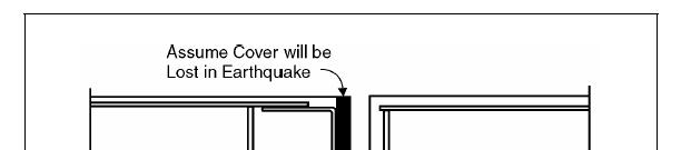

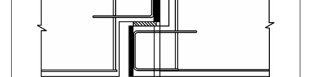


37 Evaluation Method C Note that for each component, several c/d ratios (r i ) may need to be calculated. Example 1: Support lengths and bearings
38 Evaluation Method C Example 2: Columns Five (5) c/d ratios should be found for each column for the following: Anchorage length of longitudinal rebar, r ca Transverse confinement, r cc Splice length, r cs Shear force, r cv r confinement r splice Bending moment, r ec r anchorage
39 P-Δ Effects in Bridge Columns F, Δ h P F P K K pier pier h K pier F Δ A P Equilibrium in deformed state requires ΣM A = 0, i.e. F h + P Δ = (K pier Δ)h h Therefore F = (K pier P / h) Δ = K' pier Δ
40 P-Δ Effects in Elastic Bridge Columns Force F Elastic capacity curve for column, slope = K pier Elastic capacity curve with P-Δ included, slope = K' pier Loss in capacity at displacement Δ, due to P-Δ effect = PΔ / h Δ Displacement
41 P-Δ Effects in Yielding Bridge Columns Elasto-plastic capacity curve for column; initial slope = K pier, second slope = 0 Force F Elasto-plastic capacity curve with P-Δ included; initial slope = K' pier second slope = - P/h Loss in capacity at displacement Δ due to P-Δ effect = PΔ / h Δ yield Δ Displacement
42 P-Δ Effects in Yielding Bridge Columns Elasto-plastic capacity curve for column; initial slope = K pier, second slope = 0 Force F Elasto-plastic capacity curve with P-Δ included; initial slope = K' pier second slope = - P/h Loss in capacity at displacement Δ due to P-Δ effect = PΔ / h Δ yield Δ Displacement
43 P-Δ Effects in Yielding Bridge Columns AASHTO LRFD Specifications and FHWA Retrofit Manual require that if PΔ / h>025mp/h 0.25 h a refined analysis must be undertaken that explicitly includes nonlinear geometric effects (P-Δ) Encouraged to limit Δ such that Δ max < 0.25 Mp / P
44 Learning Outcomes Explain difference between elastic forces, actual forces and Modified Design Forces Define a plastic hinge Explain Capacity Protection ti Philosophyh Describe the Component Capacity/Demand Retrofit Method (Method C) Describe how P-Δ effects are considered in design
45 Thank you
Seismic Pushover Analysis Using AASHTO Guide Specifications for LRFD Seismic Bridge Design
 Seismic Pushover Analysis Using AASHTO Guide Specifications for LRFD Seismic Bridge Design Elmer E. Marx, Alaska Department of Transportation and Public Facilities Michael Keever, California Department
Nonlinear static analysis PUSHOVER
 Nonlinear static analysis PUSHOVER Adrian DOGARIU European Erasmus Mundus Master Course Sustainable Constructions under Natural Hazards and Catastrophic Events 520121-1-2011-1-CZ-ERA MUNDUS-EMMC Structural
EUROCODE EN SEISMIC DESIGN OF BRIDGES
 Brussels, 18-20 February 2008 Dissemination of information workshop 1 EUROCODE EN1998-2 SEISMIC DESIGN OF BRIDGES Basil Kolias Basic Requirements Brussels, 18-20 February 2008 Dissemination of information
ENERGY DIAGRAM w/ HYSTERETIC
 ENERGY DIAGRAM ENERGY DIAGRAM w/ HYSTERETIC IMPLIED NONLINEAR BEHAVIOR STEEL STRESS STRAIN RELATIONSHIPS INELASTIC WORK DONE HYSTERETIC BEHAVIOR MOMENT ROTATION RELATIONSHIP IDEALIZED MOMENT ROTATION DUCTILITY
Seismic design of bridges
 NATIONAL TECHNICAL UNIVERSITY OF ATHENS LABORATORY FOR EARTHQUAKE ENGINEERING Seismic design of bridges Lecture 3 Ioannis N. Psycharis Capacity design Purpose To design structures of ductile behaviour
Chapter 6 Seismic Design of Bridges. Kazuhiko Kawashima Tokyo Institute of Technology
 Chapter 6 Seismic Design of Bridges Kazuhiko Kawashima okyo Institute of echnology Seismic Design Loading environment (dead, live, wind, earthquake etc) Performance criteria for gravity (deflection, stresses)
Pushover Seismic Analysis of Bridge Structures
 Pushover Seismic Analysis of Bridge Structures Bernardo Frère Departamento de Engenharia Civil, Arquitectura e Georrecursos, Instituto Superior Técnico, Technical University of Lisbon, Portugal October
Soil-Structure Interaction in Nonlinear Pushover Analysis of Frame RC Structures: Nonhomogeneous Soil Condition
 ABSTRACT: Soil-Structure Interaction in Nonlinear Pushover Analysis of Frame RC Structures: Nonhomogeneous Soil Condition G. Dok ve O. Kırtel Res. Assist., Department of Civil Engineering, Sakarya University,
CHAPTER 5. T a = 0.03 (180) 0.75 = 1.47 sec 5.12 Steel moment frame. h n = = 260 ft. T a = (260) 0.80 = 2.39 sec. Question No.
 0.75 = 1.47 sec 5.12 Steel moment frame. h n = = 260 ft. T a = (260) 0.80 = 2.39 sec. Question No.") CHAPTER 5 Question Brief Explanation No. 5.1 From Fig. IBC 1613.5(3) and (4) enlarged region 1 (ASCE 7 Fig. -3 and -4) S S = 1.5g, and S 1 = 0.6g. The g term is already factored in the equations, thus
CHAPTER 5 Question Brief Explanation No. 5.1 From Fig. IBC 1613.5(3) and (4) enlarged region 1 (ASCE 7 Fig. -3 and -4) S S = 1.5g, and S 1 = 0.6g. The g term is already factored in the equations, thus
Lecture-08 Gravity Load Analysis of RC Structures
 Lecture-08 Gravity Load Analysis of RC Structures By: Prof Dr. Qaisar Ali Civil Engineering Department UET Peshawar www.drqaisarali.com 1 Contents Analysis Approaches Point of Inflection Method Equivalent
Seminar Bridge Design with Eurocodes
 Seminar Bridge Design with Eurocodes JRC Ispra, 1-2 October 2012 1 EU-Russia Regulatory Dialogue: Construction Sector Subgroup Seminar Bridge Design with Eurocodes JRC-Ispra, 1-2 October 2012 Organized
BI-DIRECTIONAL SEISMIC ANALYSIS AND DESIGN OF BRIDGE STEEL TRUSS PIERS ALLOWING A CONTROLLED ROCKING RESPONSE
 Proceedings of the 8 th U.S. National Conference on Earthquake Engineering April 18-22, 2006, San Francisco, California, USA Paper No. 1954 BI-DIRECTIONAL SEISMIC ANALYSIS AND DESIGN OF BRIDGE STEEL TRUSS
Comparison of Structural Models for Seismic Analysis of Multi-Storey Frame Buildings
 Comparison of Structural Models for Seismic Analysis of Multi-Storey Frame Buildings Dj. Ladjinovic, A. Raseta, A. Radujkovic & R. Folic University of Novi Sad, Faculty of Technical Sciences, Novi Sad,
Seismic Performance of RC Building Using Spectrum Response and Pushover Analyses
 Seismic Performance of RC Building Using Spectrum Response and Pushover Analyses Mehani Youcef (&), Kibboua Abderrahmane, and Chikh Benazouz National Earthquake Engineering Research Center (CGS), Algiers,
DETERMINATION OF PERFORMANCE POINT IN CAPACITY SPECTRUM METHOD
 ISSN (Online) : 2319-8753 ISSN (Print) : 2347-6710 International Journal of Innovative Research in Science, Engineering and Technology An ISO 3297: 2007 Certified Organization, Volume 2, Special Issue
Design of Earthquake-Resistant Structures
 NATIONAL TECHNICAL UNIVERSITY OF ATHENS LABORATORY OF EARTHQUAKE ENGINEERING Design of Earthquake-Resistant Structures Basic principles Ioannis N. Psycharis Basic considerations Design earthquake: small
SEISMIC RESPONSE OF SINGLE DEGREE OF FREEDOM STRUCTURAL FUSE SYSTEMS
 3 th World Conference on Earthquake Engineering Vancouver, B.C., Canada August -6, 4 Paper No. 377 SEISMIC RESPONSE OF SINGLE DEGREE OF FREEDOM STRUCTURAL FUSE SYSTEMS Ramiro VARGAS and Michel BRUNEAU
Seismic Assessment of a RC Building according to FEMA 356 and Eurocode 8
 1 Seismic Assessment of a RC Building according to FEMA 356 and Eurocode 8 Ioannis P. GIANNOPOULOS 1 Key words: Pushover analysis, FEMA 356, Eurocode 8, seismic assessment, plastic rotation, limit states
Finite Element Modelling with Plastic Hinges
 01/02/2016 Marco Donà Finite Element Modelling with Plastic Hinges 1 Plastic hinge approach A plastic hinge represents a concentrated post-yield behaviour in one or more degrees of freedom. Hinges only
Moment redistribution of continuous composite I-girders with high strength steel
 Moment redistribution of continuous composite I-girders with high strength steel * Hyun Sung Joo, 1) Jiho Moon, 2) Ik-Hyun sung, 3) Hak-Eun Lee 4) 1), 2), 4) School of Civil, Environmental and Architectural
PLATE GIRDERS II. Load. Web plate Welds A Longitudinal elevation. Fig. 1 A typical Plate Girder
 16 PLATE GIRDERS II 1.0 INTRODUCTION This chapter describes the current practice for the design of plate girders adopting meaningful simplifications of the equations derived in the chapter on Plate Girders
THREE-DIMENSIONAL NONLINEAR DEGRADING MODEL FOR EARTHQUAKE RESPONSE ANALYSES OF CONCRETE BRIDGES
 The 4 th World Conference on Earthquake Engineering October 2-7, 28, Beijing, China THREE-DIMENSIONAL NONLINEAR DEGRADING MODEL FOR EARTHQUAKE RESPONSE ANALYSES OF CONCRETE BRIDGES V. Phung and D. Lau
Eurocode 8 Part 3: Assessment and retrofitting of buildings
 in the Euro-Mediterranean Area Eurocode 8 Part 3: Assessment and retrofitting of buildings Paolo Emilio Pinto Università di Roma La Sapienza Urgency of guidance documents for assessment and retrofit in
P-Delta Effects in Limit State Design of Slender RC Bridge Columns
 P-Delta Effects in Limit State Design of Slender RC Bridge Columns Pedro F. Silva, & Arash Sangtarashha The George Washington University, Washington, DC, U.S.A. Rigoberto Burgueño Michigan State University,
INELASTIC SEISMIC DISPLACEMENT RESPONSE PREDICTION OF MDOF SYSTEMS BY EQUIVALENT LINEARIZATION
 INEASTIC SEISMIC DISPACEMENT RESPONSE PREDICTION OF MDOF SYSTEMS BY EQUIVAENT INEARIZATION M. S. Günay 1 and H. Sucuoğlu 1 Research Assistant, Dept. of Civil Engineering, Middle East Technical University,
SEISMIC PERFORMANCE FACTORS FOR STEEL ECCENTRICALLY BRACED FRAMES
 SEISMIC PERFORMANCE FACTORS FOR STEEL ECCENTRICALLY BRACED FRAMES Cem Topkaya Professor of Civil Engineering Middle East Technical University Ankara, Turkey e-mail: ctopkaya@metu.edu.tr Ahmet Kuşyılmaz
This Technical Note describes how the program checks column capacity or designs reinforced concrete columns when the ACI code is selected.
 COMPUTERS AND STRUCTURES, INC., BERKELEY, CALIFORNIA DECEMBER 2001 CONCRETE FRAME DESIGN ACI-318-99 Technical Note This Technical Note describes how the program checks column capacity or designs reinforced
Appendix G Analytical Studies of Columns
 Appendix G Analytical Studies of Columns G.1 Introduction Analytical parametric studies were performed to evaluate a number of issues related to the use of ASTM A103 steel as longitudinal and transverse
IS DIRECT DISPLACEMENT BASED DESIGN VALID FOR LONG SPAN BRIDGES?
 October 1-17, 8, Beijing, China IS DIRECT DISPLACEMENT BASED DESIGN VALID FOR LONG SPAN BRIDGES? G. Adhikari 1 L. Petrini and G. M. Calvi 3 1 PhD Student, European School for Advanced Studies in Reduction
Lap splice length and details of column longitudinal reinforcement at plastic hinge region
 Lap length and details of column longitudinal reinforcement at plastic hinge region Hong-Gun Park 1) and Chul-Goo Kim 2) 1), 2 Department of Architecture and Architectural Engineering, Seoul National University,
Influence of cracked inertia and moment-curvature curve idealization on pushover analysis
 Influence of cracked inertia and moment-curvature curve idealization on pushover analysis Vivier Aurélie, Sekkat Dayae, Montens Serge Systra, 3 avenue du Coq, 75009 Paris SUMMARY: The pushover analysis
Influence of residual stresses in the structural behavior of. tubular columns and arches. Nuno Rocha Cima Gomes
 October 2014 Influence of residual stresses in the structural behavior of Abstract tubular columns and arches Nuno Rocha Cima Gomes Instituto Superior Técnico, Universidade de Lisboa, Portugal Contact:
TABLE OF CONTENTS SECTION TITLE PAGE 2 PRINCIPLES OF SEISMIC ISOLATION OF BRIDGES 3
 TABLE OF CONTENTS SECTION TITLE PAGE 1 INTRODUCTION 1 2 PRINCIPLES OF SEISMIC ISOLATION OF BRIDGES 3 3 ANALYSIS METHODS OF SEISMICALLY ISOLATED BRIDGES 5 3.1 Introduction 5 3.2 Loadings for the Analysis
Harmonized European standards for construction in Egypt
 Harmonized European standards for construction in Egypt EN 1998 - Design of structures for earthquake resistance Jean-Armand Calgaro Chairman of CEN/TC250 Organised with the support of the Egyptian Organization
Design of a Multi-Storied RC Building
 Design of a Multi-Storied RC Building 16 14 14 3 C 1 B 1 C 2 B 2 C 3 B 3 C 4 13 B 15 (S 1 ) B 16 (S 2 ) B 17 (S 3 ) B 18 7 B 4 B 5 B 6 B 7 C 5 C 6 C 7 C 8 C 9 7 B 20 B 22 14 B 19 (S 4 ) C 10 C 11 B 23
Seismic Design of Bridges
 Seismic Design of Bridges Anat Ruangrassamee, Ph.D. Center of Excellence in Earthquake Engineering and Vibration Department of Civil Engineering Chulalongkorn Universit 1. Design philosoph Course Outline
CAPACITY SPECTRUM FOR STRUCTURES ASYMMETRIC IN PLAN
 13 th World Conference on Earthquake Engineering Vancouver, B.C., Canada August 1-6, 004 Paper No. 653 CAPACITY SPECTRUM FOR STRUCTURES ASYMMETRIC IN PLAN B. K. Raghu Prasad 1, A. Seetha Ramaiah and A.
TRANSPORTATION RESEARCH BOARD. TRB Webinar Program Direct Displacement Based Seismic Design of Bridges. Thursday, June 22, :00-3:30 PM ET
 TRANSPORTATION RESEARCH BOARD TRB Webinar Program Direct Displacement Based Seismic Design of Bridges Thursday, June 22, 2017 2:00-3:30 PM ET The Transportation Research Board has met the standards and
Earthquake Loads According to IBC IBC Safety Concept
 Earthquake Loads According to IBC 2003 The process of determining earthquake loads according to IBC 2003 Spectral Design Method can be broken down into the following basic steps: Determination of the maimum
INELASTIC RESPONSES OF LONG BRIDGES TO ASYNCHRONOUS SEISMIC INPUTS
 13 th World Conference on Earthquake Engineering Vancouver, B.C., Canada August 1-6, 24 Paper No. 638 INELASTIC RESPONSES OF LONG BRIDGES TO ASYNCHRONOUS SEISMIC INPUTS Jiachen WANG 1, Athol CARR 1, Nigel
EARTHQUAKE ANALYSIS with SAP2000
 EARTHQUAKE ANALYSIS with SAP2000 Prepared by Bob Matthews 2004 Robert Matthews Page 1 EARTHQUAKE ANALYSIS EXAMPLE The earthquake analysis capabilities of SAP2000 are demonstrated using a railroad bridge
Shear Failure Model for Flexure-Shear Critical Reinforced Concrete Columns
 Shear Failure Model for Flexure-Shear Critical Reinforced Concrete Columns W.M. Ghannoum 1 and J.P. Moehle 2 1 Assistant Professor, Dept. of Civil, Architectural, and Environmental Engineering, University
POST-PEAK BEHAVIOR OF FRP-JACKETED REINFORCED CONCRETE COLUMNS
 POST-PEAK BEHAVIOR OF FRP-JACKETED REINFORCED CONCRETE COLUMNS - Technical Paper - Tidarut JIRAWATTANASOMKUL *1, Dawei ZHANG *2 and Tamon UEDA *3 ABSTRACT The objective of this study is to propose a new
STATIC NONLINEAR ANALYSIS. Advanced Earthquake Engineering CIVIL-706. Instructor: Lorenzo DIANA, PhD
 STATIC NONLINEAR ANALYSIS Advanced Earthquake Engineering CIVIL-706 Instructor: Lorenzo DIANA, PhD 1 By the end of today s course You will be able to answer: What are NSA advantages over other structural
Buildings with high seismic risk. Unsafe Buildings
 Buildings with high seismic risk Unsafe Buildings AN EQUIVALENT LINEARIZATION PROCEDURE FOR DISPLACEMENT-BASED SEISMIC ASSESSMENT M. Selim GÜNAY and Haluk SUCUOĞLU Middle East Technical University Ankara,
OS MODELER - EXAMPLES OF APPLICATION Version 1.0. (Draft)
") OS MODELER - EXAMPLES OF APPLICATION Version 1.0 (Draft) Matjaž Dolšek February 2008 Content 1. Introduction... 1 2. Four-storey reinforced concrete frame designed according to EC8... 2 2.1. Description
OS MODELER - EXAMPLES OF APPLICATION Version 1.0 (Draft) Matjaž Dolšek February 2008 Content 1. Introduction... 1 2. Four-storey reinforced concrete frame designed according to EC8... 2 2.1. Description
FHWA Bridge Design Guidance No. 1 Revision Date: July 21, Load Rating Evaluation of Gusset Plates in Truss Bridges
 FHWA Bridge Design Guidance No. 1 Revision Date: July 21, 2008 Load Rating Evaluation of Gusset Plates in Truss Bridges By Firas I. Sheikh Ibrahim, PhD, PE Part B Gusset Plate Resistance in Accordance
Sabah Shawkat Cabinet of Structural Engineering Walls carrying vertical loads should be designed as columns. Basically walls are designed in
 Sabah Shawkat Cabinet of Structural Engineering 17 3.6 Shear walls Walls carrying vertical loads should be designed as columns. Basically walls are designed in the same manner as columns, but there are
Improving the earthquake performance of bridges using seismic isolation
 Improving the earthquake performance of bridges using seismic isolation Ian Buckle Professor, University of Nevada Reno TRB Webinar February 10, 2016 Sponsored by TRB Committee AFF50: Seismic Design and
Appendix K Design Examples
 Appendix K Design Examples Example 1 * Two-Span I-Girder Bridge Continuous for Live Loads AASHTO Type IV I girder Zero Skew (a) Bridge Deck The bridge deck reinforcement using A615 rebars is shown below.
Collapse modes of structures under strong motions of earthquake
 ANNALS OF GEOPHYSICS, VOL. 45, N. 6, December 2002 Collapse modes of structures under strong motions of earthquake Hiroshi Akiyama Real Estate Science, School of Science and Technology, Nihon University,
Challenges in Collapse Prediction for Steel Moment Frame Structures
 Challenges in Collapse Prediction for Steel Moment Frame Structures Helmut Krawinkler Farzin Zareian Dimitrios Lignos Loading History Effects Identical Steel Beams Component Models with Deterioration 1.
five Mechanics of Materials 1 ARCHITECTURAL STRUCTURES: FORM, BEHAVIOR, AND DESIGN DR. ANNE NICHOLS SUMMER 2017 lecture
 ARCHITECTURAL STRUCTURES: FORM, BEHAVIOR, AND DESIGN DR. ANNE NICHOLS SUMMER 2017 lecture five mechanics www.carttalk.com of materials Mechanics of Materials 1 Mechanics of Materials MECHANICS MATERIALS
THE EFFECTS OF LONG-DURATION EARTHQUAKES ON CONCRETE BRIDGES WITH POORLY CONFINED COLUMNS THERON JAMES THOMPSON
 THE EFFECTS OF LONG-DURATION EARTHQUAKES ON CONCRETE BRIDGES WITH POORLY CONFINED COLUMNS By THERON JAMES THOMPSON A thesis submitted in partial fulfillment of the requirement for the degree of MASTERS
DEFORMATION CAPACITY OF OLDER RC SHEAR WALLS: EXPERIMENTAL ASSESSMENT AND COMPARISON WITH EUROCODE 8 - PART 3 PROVISIONS
 DEFORMATION CAPACITY OF OLDER RC SHEAR WALLS: EXPERIMENTAL ASSESSMENT AND COMPARISON WITH EUROCODE 8 - PART 3 PROVISIONS Konstantinos CHRISTIDIS 1, Emmanouil VOUGIOUKAS 2 and Konstantinos TREZOS 3 ABSTRACT
Prof. A. Meher Prasad. Department of Civil Engineering Indian Institute of Technology Madras
 Prof. A. Meher Prasad Department of Civil Engineering Indian Institute of Technology Madras email: prasadam@iitm.ac.in Dynamic - Loads change with time Nonlinear - Loaded beyond Elastic Limit Type Usual
CE5510 Advanced Structural Concrete Design - Design & Detailing of Openings in RC Flexural Members-
 CE5510 Advanced Structural Concrete Design - Design & Detailing Openings in RC Flexural Members- Assoc Pr Tan Kiang Hwee Department Civil Engineering National In this lecture DEPARTMENT OF CIVIL ENGINEERING
Design Calculations & Real Behaviour (Hambly s Paradox)
") Design Calculations & Real Behaviour (Hambly s Paradox) Carol Serban 1. Introduction The present work is meant to highlight the idea that engineering design calculations (lately most of the time using
Design Calculations & Real Behaviour (Hambly s Paradox) Carol Serban 1. Introduction The present work is meant to highlight the idea that engineering design calculations (lately most of the time using
A METHOD OF LOAD INCREMENTS FOR THE DETERMINATION OF SECOND-ORDER LIMIT LOAD AND COLLAPSE SAFETY OF REINFORCED CONCRETE FRAMED STRUCTURES
 A METHOD OF LOAD INCREMENTS FOR THE DETERMINATION OF SECOND-ORDER LIMIT LOAD AND COLLAPSE SAFETY OF REINFORCED CONCRETE FRAMED STRUCTURES Konuralp Girgin (Ph.D. Thesis, Institute of Science and Technology,
Probabilistic damage control seismic design of bridges using structural reliability concept
 Probabilistic damage control seismic design of bridges using structural reliability concept A. Saini Doctoral Student, University of Nevada, Reno, NV, USA A. Vosooghi Bridge Engineer III, Ph.D., P.E.,
EARTHQUAKE SIMULATION TESTS OF BRIDGE COLUMN MODELS DAMAGED DURING 1995 KOBE EARTHQUAKE
 EARTHQUAKE SIMULATION TESTS OF BRIDGE COLUMN MODELS DAMAGED DURING 1995 KOBE EARTHQUAKE J. Sakai 1, S. Unjoh 2 and H. Ukon 3 1 Senior Researcher, Center for Advanced Engineering Structural Assessment and
NUMERICAL EVALUATION OF THE ROTATIONAL CAPACITY OF STEEL BEAMS AT ELEVATED TEMPERATURES
 8 th GRACM International Congress on Computational Mechanics Volos, 12 July 15 July 2015 NUMERICAL EVALUATION OF THE ROTATIONAL CAPACITY OF STEEL BEAMS AT ELEVATED TEMPERATURES Savvas Akritidis, Daphne
EFFECT OF SHEAR REINFORCEMENT ON FAILURE MODE OF RC BRIDGE PIERS SUBJECTED TO STRONG EARTHQUAKE MOTIONS
 EFFECT OF SHEAR REINFORCEMENT ON FAILURE MODE OF RC BRIDGE PIERS SUBJECTED TO STRONG EARTHQUAKE MOTIONS Atsuhiko MACHIDA And Khairy H ABDELKAREEM SUMMARY Nonlinear D FEM was utilized to carry out inelastic
Chapter 1 General Introduction Instructor: Dr. Mürüde Çelikağ Office : CE Building Room CE230 and GE241
 CIVL222 STRENGTH OF MATERIALS Chapter 1 General Introduction Instructor: Dr. Mürüde Çelikağ Office : CE Building Room CE230 and GE241 E-mail : murude.celikag@emu.edu.tr 1. INTRODUCTION There are three
999 TOWN & COUNTRY ROAD ORANGE, CALIFORNIA TITLE PUSHOVER ANALYSIS EXAMPLE BY R. MATTHEWS DATE 5/21/01
 DESCRIPTION Nonlinear static (pushover) analysis will be performed on a railroad bridge bent using several methods to determine its ultimate lateral deflection capability. 1. SAP2000 Nonlinear with axial-moment
PEER/SSC Tall Building Design. Case study #2
 PEER/SSC Tall Building Design Case study #2 Typical Plan View at Ground Floor and Below Typical Plan View at 2 nd Floor and Above Code Design Code Design Shear Wall properties Shear wall thickness and
Design of Beams (Unit - 8)
") Design of Beams (Unit - 8) Contents Introduction Beam types Lateral stability of beams Factors affecting lateral stability Behaviour of simple and built - up beams in bending (Without vertical stiffeners)
Design of Beams (Unit - 8) Contents Introduction Beam types Lateral stability of beams Factors affecting lateral stability Behaviour of simple and built - up beams in bending (Without vertical stiffeners)
Guidelines on Foundation Loading and Deformation Due to Liquefaction Induced Lateral Spreading
 Guidelines on Foundation Loading and Deformation Due to Liquefaction Induced Lateral Spreading February, 2011 1 INTRODUCTION Past earthquakes offer many examples of bridges that either collapsed or incurred
A Modified Response Spectrum Analysis Procedure (MRSA) to Determine the Nonlinear Seismic Demands of Tall Buildings
 to Determine the Nonlinear Seismic Demands of Tall Buildings") Fawad A. Najam Pennung Warnitchai Asian Institute of Technology (AIT), Thailand Email: fawad.ahmed.najam@ait.ac.th A Modified Response Spectrum Analysis Procedure (MRSA) to Determine the Nonlinear Seismic
Fawad A. Najam Pennung Warnitchai Asian Institute of Technology (AIT), Thailand Email: fawad.ahmed.najam@ait.ac.th A Modified Response Spectrum Analysis Procedure (MRSA) to Determine the Nonlinear Seismic
CAPACITY DESIGN FOR TALL BUILDINGS WITH MIXED SYSTEM
 13 th World Conference on Earthquake Engineering Vancouver, B.C., Canada August 1-6, 24 Paper No. 2367 CAPACITY DESIGN FOR TALL BUILDINGS WITH MIXED SYSTEM M.UMA MAHESHWARI 1 and A.R.SANTHAKUMAR 2 SUMMARY
Displacement-based methods EDCE: Civil and Environmental Engineering CIVIL Advanced Earthquake Engineering
 Displacement-based methods EDCE: Civil and Environmental Engineering CIVIL 706 - Advanced Earthquake Engineering EDCE-EPFL-ENAC-SGC 2016-1- Content! Link to force-based methods! Assumptions! Reinforced
Design of Reinforced Concrete Structures (II)
") Design of Reinforced Concrete Structures (II) Discussion Eng. Mohammed R. Kuheil Review The thickness of one-way ribbed slabs After finding the value of total load (Dead and live loads), the elements are
Design of Reinforced Concrete Structures (II) Discussion Eng. Mohammed R. Kuheil Review The thickness of one-way ribbed slabs After finding the value of total load (Dead and live loads), the elements are
Non-Linear Modeling of Reinforced Concrete Structures for Seismic Applications
 2/18/21 Non-Linear Modeling of Reinforced Concrete Structures for Seismic Applications Luis A. Montejo Assistant Professor Department of Engineering Science and Materials University of Puerto Rico at Mayaguez
Comparative study between the push-over analysis and the method proposed by the RPA for the evaluation of seismic reduction coefficient
 33, Issue (27) 5-23 Journal of Advanced Research in Materials Science Journal homepage: www.akademiabaru.com/arms.html ISSN: 2289-7992 Comparative study between the push-over analysis and the method proposed
FINITE ELEMENT ANALYSIS OF TAPERED COMPOSITE PLATE GIRDER WITH A NON-LINEAR VARYING WEB DEPTH
 Journal of Engineering Science and Technology Vol. 12, No. 11 (2017) 2839-2854 School of Engineering, Taylor s University FINITE ELEMENT ANALYSIS OF TAPERED COMPOSITE PLATE GIRDER WITH A NON-LINEAR VARYING
Inelastic shear response of RC coupled structural walls
 Inelastic shear response of RC coupled structural walls E. Morariu EDIT Structural, Bucuresti, Rumania. T. Isakovic, N. Eser & M. Fischinger Faculty of Civil and Geodetic Engineering, University of Ljubljana,
midas Civil Dynamic Analysis
 Edgar De Los Santos Midas IT August 23 rd 2017 Contents: Introduction Eigen Value Analysis Response Spectrum Analysis Pushover Analysis Time History Analysis Seismic Analysis Seismic Analysis The seismic
Influence of First Shape Factor in Behaviour of Rubber Bearings Base Isolated Buildings.
 ISSN (Online) 2347-327 Influence of First Shape Factor in Behaviour of Rubber Bearings Base Isolated Buildings. Luan MURTAJ 1, Enkelejda MURTAJ 1 Pedagogue, Department of Structural Mechanics Faculty of
PACIFIC EARTHQUAKE ENGINEERING RESEARCH CENTER
 PACIFIC EARTHQUAKE ENGINEERING RESEARCH CENTER PACIFIC EARTHQUAKE ENGINEERING Performance and Reliability of Exposed Column Base Plate Connections for Steel Moment-Resisting Frames Ady Aviram Bozidar Stojadinovic
Seismic performance evaluation of existing RC buildings designed as per past codes of practice
 Sādhanā Vol. 37, Part 2, April 2012, pp. 281 297. c Indian Academy of Sciences Seismic performance evaluation of existing RC buildings designed as per past codes of practice 1. Introduction K RAMA RAJU,
Coupling Beams of Shear Walls
 Coupling Beams of Shear Walls Modelling Procedure for the Seismic Analysis of RC Structures João Miguel Damião Bezelga (1) July 215 (1) Instituto Superior Técnico Universidade de Lisboa, Av. Rovisco Pais,
A. Belejo, R. Bento & C. Bhatt Instituto Superior Técnico, Lisbon, Portugal 1.INTRODUCTION
 Comparison of different computer programs to predict the seismic performance of SPEAR the SPEAR building building by means of by means of Pushover Analysis A. Belejo, R. Bento & C. Bhatt Instituto Superior
INFLUENCE OF FLANGE STIFFNESS ON DUCTILITY BEHAVIOUR OF PLATE GIRDER
 International Journal of Civil Structural 6 Environmental And Infrastructure Engineering Research Vol.1, Issue.1 (2011) 1-15 TJPRC Pvt. Ltd.,. INFLUENCE OF FLANGE STIFFNESS ON DUCTILITY BEHAVIOUR OF PLATE
Influence of the Plastic Hinges Non-Linear Behavior on Bridges Seismic Response
 Influence of the Plastic Hinges Non-Linear Behavior on Bridges Seismic Response Miguel Arriaga e Cunha, Luís Guerreiro & Francisco Virtuoso Instituto Superior Técnico, Universidade Técnica de Lisboa, Lisboa
Chapter 4. Test results and discussion. 4.1 Introduction to Experimental Results
 Chapter 4 Test results and discussion This chapter presents a discussion of the results obtained from eighteen beam specimens tested at the Structural Technology Laboratory of the Technical University
The Pennsylvania State University. The Graduate School. College of Engineering EVALUATION OF LIMIT DESIGN FOR EARTHQUAKE-RESISTANT MASONRY WALLS
 The Pennsylvania State University The Graduate School College of Engineering EVALUATION OF LIMIT DESIGN FOR EARTHQUAKE-RESISTANT MASONRY WALLS A Thesis in Architectural Engineering by Bradley S. Frederick
STEEL JOINTS - COMPONENT METHOD APPLICATION
 Bulletin of the Transilvania University of Braşov Vol. 5 (54) - 2012 Series 1: Special Issue No. 1 STEEL JOINTS - COPONENT ETHOD APPLICATION D. RADU 1 Abstract: As long as the rotation joint stiffness
Chapter 5 Commentary STRUCTURAL ANALYSIS PROCEDURES
 Chapter 5 Commentary STRUCTURAL ANALYSIS PROCEDURES 5.1 GENERAL The equivalent lateral force (ELF) procedure specified in Sec. 5.2 is similar in its basic concept to SEAOC recommendations in 1968, 1973,
Boundary Nonlinear Dynamic Analysis
 Boundary Nonlinear Dynamic Analysis Damper type Nonlinear Link Base Isolator type Nonlinear Link Modal Nonlinear Analysis : Equivalent Dynamic Load Damper type Nonlinear Link Visco-Elastic Damper (VED)
Nonlinear Analysis of Reinforced Concrete Bridges under Earthquakes
 6 th International Conference on Advances in Experimental Structural Engineering 11 th International Workshop on Advanced Smart Materials and Smart Structures Technology August 1-2, 2015, University of
Seismic Design of New R.C. Structures
 Seismic Design Philosophy Main Concepts Seismic Design of New R.C. Structures Prof. Stephanos E. Dritsos University of Patras, Greece. Energy dissipation Ductility Capacity design Learning from Earthquakes
Study of Rotational Column with Plastic Hinge
 Study of Rotational Column with Plastic Hinge Presented by: Michael Long, Rice University Corey Bergad, Bates College REU Interns, SUNY at Buffalo Advisor: Andrei M. Reinhorn, Ph.D., P.E. Professor and
Seismic design of bridges
 NAIONAL ECHNICAL UNIVERSIY OF AHENS LABORAORY FOR EARHQUAKE ENGINEERING Seismic design of bridges Lecture 4 Ioannis N. Psycharis Seismic isolation of bridges I. N. Psycharis Seismic design of bridges 2
SEISMIC PERFORMANCE OF CONCRETE COLUMNS WITH INADEQUATE TRANSVERSE REINFORCEMENT. Alistair Boys 1 Des K. Bull 2 Stefano Pampanin 3 ABSTRACT
 SEISMIC PERFORMANCE OF CONCRETE COLUMNS WITH INADEQUATE TRANSVERSE REINFORCEMENT. Alistair Boys 1 Des K. Bull 2 Stefano Pampanin 3 ABSTRACT Existing New Zealand building stock contains a significant number
Seismic resistance of a reinforced concrete building before and after retrofitting Part II: The retrofitted building
 Seismic resistance of a reinforced concrete building before and after retrofitting Part II: The retrofitted building M. Marletta, S. Vaccaro & I. Caliò Department of Civil and Environmental Engineering
Nonlinear static (pushover) analysis will be performed on a railroad bridge bent using wframe to determine its ultimate lateral deflection capability.
 analysis will be performed on a railroad bridge bent using wframe to determine its ultimate lateral deflection capability.") DESCRIPTION Nonlinear static (pushover) analysis will be performed on a railroad bridge bent using wframe to determine its ultimate lateral deflection capability. Moment hinges are based on Caltrans material
DESCRIPTION Nonlinear static (pushover) analysis will be performed on a railroad bridge bent using wframe to determine its ultimate lateral deflection capability. Moment hinges are based on Caltrans material
EXAMPLE OF PILED FOUNDATIONS
 EXAMPLE OF PILED FOUNDATIONS The example developed below is intended to illustrate the various steps involved in the determination of the seismic forces developed in piles during earthquake shaking. The
Behavior and Modeling of Existing Reinforced Concrete Columns
 Behavior and Modeling of Existing Reinforced Concrete Columns Kenneth J. Elwood University of British Columbia with contributions from Jose Pincheira, Univ of Wisconsin John Wallace, UCLA Questions? What
STRAIN ASSESSMENT USFOS
 1 STRAIN ASSESSMENT IN USFOS 2 CONTENTS: 1 Introduction...3 2 Revised strain calculation model...3 3 Strain predictions for various characteristic cases...4 3.1 Beam with concentrated load at mid span...
 Second Order Analysis In the previous classes we looked at a method that determines the load corresponding to a state of bifurcation equilibrium of a perfect frame by eigenvalye analysis The system was