Triaxial Shear Test. o The most reliable method now available for determination of shear strength parameters.
|
|
|
- Kelly Mitchell
- 5 years ago
- Views:
Transcription
1 TOPICS Introduction Components of Shear Strength of Soils Normal and Shear Stresses on a Plane Mohr-Coulomb Failure Criterion Laboratory Shear Strength Testing Direct Shear Test Triaxial Compression Test Unconfined Compression Test Field Testing (Vane test)
2 Triaxial Shear Test o The most reliable method now available for determination of shear strength parameters. o Entire books have been written on triaxial test. o The test is used to measure the shear strength of a soil under controlled drainage conditions. o The test is designed to simulate actual field conditions. representative soil sample s vc z s vc + Ds z s hc s hc s hc s hc s vc s vc + Ds Before construction After and during construction
3 Triaxial Shear Test o The test is called triaxial because the three principle stresses are assumed to be known and controlled. o The triaxial test is much more complicated than the direct shear but also much more versatile. o The failure plane can occur anywhere and we can control the stress paths to failure reasonably well, which means that complex stress paths in the field can more effectively be modeled in the laboratory with the triaxial test.
4 Principles of Triaxial Test To simulate field conditions, soil samples is subjected to the following stages: 1. Saturation of sample (Check of B value) 2. Applying confining (cell) pressure (s 3 ) is applied on the soil sample. The confining pressure is within the range of that subjected in the field. 3. Apply an increasing vertical stress (Ds = s 1 - s 3 ) -termed the deviator stress- until failure. 4. The specimen is free to fail on any weak plane or, as sometimes occurs, to simply BULGE. Ds s 3 = Confining pressure = Cell pressure = All-around pressure s 3 s 3 s 3 Deviator Principle Stress, Ds or Ds d = s 1 -s 3


5 Triaxial Shear Test

6 Triaxial Shear Test


7 Triaxial Shear Test Device Piston (to apply deviatoric stress) O-ring Perspex cell Soil sample impervious membrane Porous stone Water Cell pressure Back pressure pedesta l Pore pressure or volume change Two ways for appying axial load 1. Application of dead weights or hydraulic pressure in equal increments until the specimen fails. 2. Application of axial deformation at a constant rate by means of a geared or hydraulic loading press. This is a strain-controlled test.
 Edges")


8 Specimen Preparation (undisturbed sample) Edges of the sample are carefully trimmed Sample is covered with a rubber membrane and sealed Setting up the sample in the triaxial cell Cell is completely filled with water

9 Apparatus Assembly Proving ring to measure the deviator load Dial gauge to measure vertical displacement
10 Types of Triaxial Test o Many variations of test procedure are possible with the triaxial apparatus but the three principal types of test are as follows: Confining Pressure Consolidated Consolidated Unconsolidated Shearing o Drained (CD) Test o Undrained (CU)Test o Undrained (UU) Test o Depends on whether drainage is allowed or not during the confining or shearing stage. o The different types of triaxial test are commonly designated by a twoletter symbol. The first letter refers to what happens BEFORE SHEAR that is whether the specimen is consolidated or not. The second letter refers to the drainage conditions during SHEAR, CD, CU, UU.
11 Types of Triaxial Test Test Drainage during confinement Drainage during shear Pore water pressure build up? Total or Effective Type of test duration CD Open Open No if the test is slow Effective Slow for clay S- test CU Open Closed Yes Total Effective if p.w.p is measured UU Closed Closed Yes Total Fast Q-test
12 Types of Triaxial Test Step 1 s 3 Step 2 (Ds) = s 1 - s 3 deviator stress s 3 s 3 s 3 s 3 s 3 s 3 + Ds Under Confining (cell) pressure s 3 Shearing (loading) Is the drainage valve open? Is the drainage valve open? yes no yes no Consolidated sample Unconsolidated sample Drained loading Undrained loading
13 Types of Triaxial Test Step 1 Under Confining (cell) pressure s 3 Step 2 Shearing (loading) Is the drainage valve open? Is the drainage valve open? yes no yes no Consolidated sample Unconsolidated sample Drained loading Undrained loading CD test UU test CU test
14 TOPICS Introduction Components of Shear Strength of Soils Normal and Shear Stresses on a Plane Mohr-Coulomb Failure Criterion Laboratory Shear Strength Testing Direct Shear Test Triaxial Compression Test (CD test) Unconfined Compression Test Field Testing (Vane test)
15 I. Consolidated Drained Test (CD Test) No excess pore pressure throughout the test Very slow shearing to avoid build-up of pore pressure - hence this test is termed the S-test (for slow test) Gives C and Can be days! Note that at all the times during CD test, the pore water pressure is essentially zero. Use C and for analysing fully drained Situations (i.e. long term stability, very slow loading)
16 Stress conditions for the consolidated drained test Total, s = Neutral, u + Effective, s Step 1: At the end of consolidation s 3 s 3 = s 3 Drainage s 3 0 s 3 = s 3 Step 2: During axial stress increase s 3 + Ds s V = s 3 + Ds = s 1 Drainage s 3 0 s h = s 3 = s 3 Step 3: At failure s 3 + Ds f s Vf = s 3 + Ds f = s 1f Drainage s 3 0 s hf = s 3 = s 3f
17 Consolidated Drained Test (CD Test) In saturated soil, the change in the volume of the specimen (DVc) that takes place during consolidation can be obtained from the volume of pore water drained. Volume change of specimen caused by chamber-confining pressure Volume change in loose sand and normally consolidated clay during deviator stress application Volume change in dense sand and overconsolidated clay during deviator stress application
18 Deviator stress, Ds d Volume change of the sample Compression Expansion Stress-strain relationship during shearing (CD Test) Dense sand or OC clay (Ds d ) f (Ds d ) f Loose sand or NC Clay Axial strain Dense sand or OC clay Axial strain Loose sand or NC clay
19 Shear stress, t Consolidated Drained Test (CD Test) Deviator stress, Ds d (Ds d ) fc (Ds d ) f b (Ds d ) fa Confining stress = s 3c Confining stress = s 3b Confining stress = s 3a Several tests on similar samples can be performed by varying the confining pressure. Then s 3 and s 1 at failure for each test are used to construct Mohr s Circle. From that M-C failure envelope can be obtained. s 1 = s 3 + (Ds d ) f Mohr Coulomb failure envelope Axial strain s 3 s 3a s 3b s 3c (Ds d ) fa s 1a s 1b s 1c s (Ds d ) fb
20 Consolidated Drained Test (CD Test) o The coordinates of the point of tangency of the failure envelope with Mohr s circle give the stresses (normal and shear) on the failure plane of the respected test.
21 Shear stress, t Failure envelopes for loose sand and NC Clay o It is usually assumed that the C parameter for normally consolidated non-cemented clays is essentially zero for all practical purposes. o Therefore, one CD test would be sufficient to determine d of sand or NC clay Mohr Coulomb failure envelope s 3a (Ds d ) fa s 1a s
22 Failure envelopes for dense sand and OC Clay t OC NC c b a c s 3 s 1 (Ds d ) f s c s For portion ab of the failure envelope For portion bc of the failure envelope
23 Shear stress, t Shear stress, t Can you think about Direct shear and Triaxial Test w.r.t. analysis of results s n Normal stress = s 3 Normal stress = s 2 t s 1 and s 3 for each test from that we plot Mohr circle and then we plot tangent to the circles (if is assumed = 0) only we need one circle) s 1 = s 3 + (Ds d ) f s 3 Shear stress at failure, t f t f3 t f2 Here we have s n and t for each test and we plot the M-C. If we need principal stress we plot Mohr circle which goes the point on the M-Cfor the concerned test t f1 Normal stress = s 1 Shear displacement Mohr Coulomb failure envelope Deviator stress, Ds d (Ds d ) fc Confining stress = s 3c Confining stress = s 3b (Dsd ) fb (Ds d ) fa Confining stress = s 3a Axial strain s 3a s 3b s 3c s 1a s 1b s 1c s Normal stress, s


24 Example 12.3

25 Example 12.4

26 Example 12.5

27 Example 12.6


28 Example 12.6

29 Example 12.7
30 Example 1 For a normally consolidated clay specimen, the results of a drained triaxial test are as follows: Chamber-confining pressure = 125 kn/m 2 Deviator stress at failure = 175 kn/m 2 Determine the soil friction angle, Solution s 1 = = 300 kn/m 2 Sin = (s 1 - s 3 )/(s 1 + s 3 ) =24.3 o Graphical Solution Check it?
31 Example 2 In a consolidated-drained triaxial test on a clay, the specimen failed at a deviator stress of 124 kn/m 2. If the effective stress friction angle is known to be 31, what was the effective confining pressure at failure? Solution Sin 31 = (s 1 - s 3 )/(s 1 + s 3 ) = 124/Sin 31 (s 1 + s 3 )=240 kn/m 2 (s 1 - s 3 ) =124 kn/m 2 Two eqs. Two unknowns s 1 =182 kn/m 2, s 3 = 58 kn/m 2 We can solve it graphically. We know so we plot M-C envelope. (s 1 -s 3 )/2 equal the radius of Mohr circle Through trial we plot the circle that touch the M-C. From that we know s 1 and s 3
32 If there is any slight difference from the analytical solution it is because the grid is not perfect square Draw a circle with a radius of 62 and move it left until toughing the M-C envelope Graphical Solution t o s
33 Example 3 Samples of dry sand are to be tested in a direct shear and a triaxial test. In the triaxial test the sample fails when the major and minor principal stresses are 450 kn/m 2 and 150 kn/m 2, respectively. What shear strength be expected in the direct shear test when the normal loading is equal to a stress of 80 kn/m 2. Solution Sin = (s 1 - s 3 )/(s 1 + s 3 ) = ( )/( ) = 0.5 Hence =30 o t = s n tan t = 80 tan 30 t = 46.2 kn/m 2 Graphical Solution t 30 o s
34 Example 4 A conventional consolidated-drained (CD) triaxial test is conducted on a sand. The cell pressure is 100 kn/m 2, and the applied axial stress at failure is 200 kn/m 2. Required: a. Plot the Mohr circle for both the initial and failure stress conditions. b. The friction angle (Assume c = 0) c. The shear stress on the failure plane at failure. d. The theoretical angle of the failure plane in the specimen. e. The orientation of the plane of the maximum obliquity f. The maximum shear stress at failure and the angle of the plane on which it acts. g. The available shear strength on the plane of maximum shear and the factor of safety on this plane.
35 Example t f o Get the required from the graph yourself
36 Some practical applications of CD analysis for clays o o The limiting drainage conditions modeled in the triaxial test refer to real filed situations. CD conditions are the most critical for the long-term steady seepage case for embankment dams and the long-term stability of excavations or slopes in both soft and stiff clays. EXAMPLES OF CD ANALYSIS 1. Embankment constructed very slowly, in layers, over a soft clay deposit t Soft clay t = in situ drained shear strength
37 Some practical applications of CD analysis for clays 2. Earth dam with steady state seepage t Core t = drained shear strength of clay core 3. Excavation or natural slope in clay t t = In situ drained shear strength
38 Note on CD test CD test simulates the long term condition in the field. Thus, C d and d should be used to evaluate the long term behavior of soils. CD test is called s-test because the stress difference is applied very slowly to ensure that no p.w.p. develops during the test. Time to failure ranges from a day to several weeks for finegrained soils. Such a long time leads to practical problems in the laboratory such as leakage of valves, seals, and the membrane that surrounds the sample. Therefore CD triaxial test is uncommon and not a popular in most soil laboratories.
39 TOPICS Introduction Components of Shear Strength of Soils Normal and Shear Stresses on a Plane Mohr-Coulomb Failure Criterion Laboratory Shear Strength Testing Direct Shear Test Triaxial Compression Test (CU test) Unconfined Compression Test Field Testing (Vane test)
40 Triaxial Shear Test Device Piston (to apply deviatoric stress) O-ring Perspex cell Soil sample impervious membrane Porous stone Water Cell pressure Back pressure pedestal Pore pressure or volume change
41 Types of Triaxial Test Step 1 Under Confining (cell) pressure s 3 Step 2 Shearing (loading) Is the drainage valve open? Is the drainage valve open? yes no yes no Consolidated sample Unconsolidated sample Drained loading Undrained loading CD test UU test CU test
42 II. Consolidated Unrained Test (CU Test) As the name implies, the test specimen is first consolidated (drainage valves open) under the desired consolidation stresses. After consolidation is complete, the drainage valves are closed, and the specimen is loaded to failure in undrained shear. Often, the pore water pressures developed during shear are measured, and both the total and effective stresses may be calculated during shear and at failure. Thus this test can either be a total or an effective stress test. This test is sometimes called the R-test. The CU test is the most common type of triaxial test.
43 II. Consolidated Unrained Test (CU Test) CD tests on clay soils take considerable time. For this reason, CU tests can be conducted on such soils with pore pressure measurements to obtain drained shear strength parameters. Because drainage is not allowed in these tests during the application of deviator stress, they can be performed quickly. Like the CD test, the axial stress can be increased incrementally or at a constant rate of strain.. Positive pore pressures occur in normally consolidated clays and negative pore pressures occur in overconsolidated clays.

44 Stress conditions for the consolidated undrained test Total, s = Neutral, u + Effective, s Step 1: At the end of consolidation s 3 s 3 = s 3 Drainage s 3 0 s 3 = s 3 Step 2: During axial stress increase s 3 + Ds s V = s 3 + Ds ± Du = s 1 No drainage s 3 ± Du s h = s 3 ± Du = s 3 Step 3: At failure s 3 + Ds f s Vf = s 3 + Ds f ± Du f = s 1f No drainage s 3 ± Du f s hf = s 3 ± Du f = s 3f
45 Stress conditions for the consolidated drained test Total, s = Neutral, u + Effective, s Step 1: At the end of consolidation s 3 s 3 = s 3 Drainage s 3 0 s 3 = s 3 Step 2: During axial stress increase s 3 + Ds s V = s 3 + Ds = s 1 Drainage s 3 0 s h = s 3 = s 3 Step 3: At failure s 3 + Ds f s Vf = s 3 + Ds f = s 1f Drainage s 3 0 s hf = s 3 = s 3f
46 Consolidated Unrained Test (CU Test) volume change in specimen caused by confining pressure Variation of pore water pressure with axial strain for loose sand and normally consolidated clay Variation of pore water pressure with axial strain for dense sand and overconsolidated clay.
47 Deviator stress, Ds d - Du + Stress-strain relationship during shearing (CU Test) (Ds d ) f (Ds d ) f Dense sand or OC clay Loose sand or NC Clay Axial strain Loose sand or NC Clay Axial strain Dense sand or OC clay -ve p.w.p is because of a tendency of the soil to dilate.
48 Shear Strength Parameters C and Shear stress, t Deviator stress, Ds d (Ds d ) fb (Ds d ) fa Mohr Coulomb failure envelope in terms of total stresses Confining stress = s 3b Confining stress = s 3a Axial strain s 1 = s 3 + (Ds d ) f s 3 Total stresses at failure C s 3a s 3b (Ds d ) fa C and are total strength parameters (Sometimes called C cu and cu which are consolidated-undrained cohesion and angle of shearing resistance, respectively). s 1a s 1b s
49 Effective and total stress Mohr circles Unlike the consolidated-drained test, the total and effective principal stresses are not the same in the consolidated-undrained test. However, since we can get both the total and effective stress circles at failure for a CU test when we measure the induced pore water pressures, it is possible to define the Mohr-Coulomb failure envelopes in terms of both total and effective stresses. For any point in the soil a total and an effective stress Mohr circle can be drawn. These are the same size with The two circles are displaced horizontally by the pore pressure, u.

50 Shear stress, t Failure envelopes for sand and NC Clay, C cu and C = 0 One CU test would be sufficient to determine (= cu ) and (= d ) of sand or NC clay Mohr Coulomb failure envelope in terms of effective stresses Mohr Coulomb failure envelope in terms of total stresses Effective Total Note: For clarity, only one set of Mohr circles is shown s 3a s 3a s 1a s 1a s or s (Ds d ) fa
51 Shear stress, t Shear Strength Parameters C and If Du is measured, then we can get both the Total and Effective stress circles at failure. s 1 = s 3 + (Ds d ) f - u f Mohr Coulomb failure envelope in terms of effective stresses u f s 3 = s 3 - u f Effective stresses at failure Mohr Coulomb failure envelope in terms of total stresses C u fa u fb C s 3a s 3b s 1a s 1b s 3a s 3b (Ds d ) fa s 1a s 1b s or s
52 Failure envelopes for NC and OC Clays NC (Same as that obtained from CD test) OC Typically, the complete Mohr failure envelopes are determined by tests on several specimens consolidated over the working stress range of the field problem. The break in the total stress envelope (point z) occurs roughly at twice s p for typical clays.
53 Note on CU test Shear Strength parameters in terms of total stresses are C and or C cu and cu Shear Strength parameters in terms of effective stresses are C and. If the specimen tends to contract or consolidate during shear, then the induced p.w.p. is +ve. This is in loose sand and N.C. clay. If the specimen tends to EXPAND or swell during shear, the Du decreases and may be ve. This occurs in Dense sand and OC clay. Since the shear strength is controlled by the effective stress in the specimen at failure, the Mohr failure hypothesis is valid in terms of effective stresses only. Hence, the point of tangency of effective M-C failure envelope to the Mohr circle of effective stress is used to define q f. It is tacitly assumed that the Mohr-Coulomb strength parameters in terms of effective stresses determined by CU tests with pore pressure measurements would be the same as those determined by CD tests. We used the same symbols, C and for the parameters determined both ways.
54 Some practical applications of CU analysis for clays o CU strengths are used for stability problems where the soils have first become fully consolidated and are at equilibrium with the existing stress system o Then, for some reasons, additional stresses are applied quickly with no drainage occurring. o Practical examples include 1. Embankment constructed rapidly over a soft clay deposit t Soft clay t = in situ undrained shear strength

55 Some practical applications of CU analysis for clays 2. Rapid drawdown behind an earth dam. No drainage of the core t Core t = Undrained shear strength of clay core 3. Rapid construction of an embankment on a natural slope t t = In situ undrained shear strength
56 Disadvantages of CU Test o It requires the measurement of Du which is not an easy task and requires a great deal of care. o The sample cannot be assured to be fully saturated. o Effect of rate of loading. The stress-deformation and strength response of clay soils is rate-dependent; that is, usually the faster you load a clay, the stronger it becomes. o There are two objectives that are incompatible. o The rate of loading in one hand shall be slow that the proper pressures measured at the ends of the specimen are the same as those occurring in the vicinity of the failure plane. o On the other hand, the rate of loading in the field may be quite rapid, and therefore for correct modeling of the field situation, the rate of loading in the laboratory sample should be comparable.

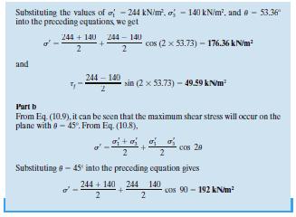
57 Example 12.8

58 Example 12.9
59 Example A normally consolidated clay was consolidated under a stress of 150 kpa, then sheared undrained in axial compression. The principal stress difference at failure was 100 kpa, and the induced pore water pressure at failure was 88 kpa. Determine:- a. The Mohr-Coulomb strength parameters in terms of both total and effective stresses analytically and graphically. b. The theoretical angle of the failure plane in the specimen. s 3 =150 kpa s 1 = =250 kpa s 3 = =62 kpa s 1 = =162 kpa Sin = 100/( ) > =14.5 o o 15 o Sin = 100/(162+62) > = 26.5 o q f = 45+ /2 = 58 o o Note: Failure plane is obtained from effective Mohr circle Measuring p.w.p. makes it possible to obtained effective strength parameters
60 Example The shear strength of a normally consolidated clay can be given by the equation t f = s tan 27. Following are the results of a consolidated-undrained test on the clay. Chamber-confining pressure = 150 kn/m 2 Deviator stress at failure = 120 kn/m 2 a. Determine the consolidated-undrained friction angle b. Pore water pressure developed in the specimen at failure s 3 =150 kn/m 2 s 1 = =270 kn/m 2 Sin = ( )/( ). > =16.6 o SIN ' = (s ' 1 - s' 3) / (s' 1 + s' 3 ) But deviatoric stress of total and effective are always equal, hence s ' 1 - s' 3 = 120 Sin 27 = 120/(s ' 1 + s' 3 ) hence (s ' 1 + s' 3 ) = 120/sin 27 = kpa The difference between the center of total and effective Mohr circles is equal to u, or u = (s 1 + s 3 )/2 (s ' 1 - s' 3 )/2 = ( )/2 (264.3)/2 Hence u = kpa
61 TOPICS Introduction Components of Shear Strength of Soils Normal and Shear Stresses on a Plane Mohr-Coulomb Failure Criterion Laboratory Shear Strength Testing Direct Shear Test Triaxial Compression Test (UU test) Unconfined Compression Test Field Testing (Vane test)
62 III. Unonsolidated Unrained Test (UU Test) Piston (to apply deviatoric stress) O-ring Cell pressure Back pressure Perspex cell Soil sample pedestal impervious membrane Porous stone Water Pore pressure or volume change Closed all along the UU test
63 Types of Triaxial Test Step 1 Under Confining (cell) pressure s 3 Step 2 Shearing (loading) Is the drainage valve open? Is the drainage valve open? yes no yes no Consolidated sample Unconsolidated sample Drained loading Undrained loading CD test UU test CU test
64 Stress conditions for the unconsolidated undrained test Step 1: After application of cell pressure No drainage Total, s = Neutral, u Effective, s s C = s 3 s C = s 3 Duc + s 3 = s 3 Du c = 0 s 3 = s 3 Du c = 0 Step 2: During application of axial load s 1 = s 3 + Ds d - Du c ± Du d No drainage s 3 + Ds d s 3 Du c ± Du d s 3 = s 3 - Du c ± Du d Step 3: At failure s 3 + Ds f s Vf = s 3 + Ds f - Du c ± Du df = s 1f No drainage s 3 Du c ± Du df s hf = s 3 - Du c ± Du df = s 3f
65 Shear Strength Parameters C and o Three identical saturated soil samples are sheared to failure in UU triaxial tests. Each sample is subjected to a different cell pressure. No water can drain at any stage. At failure the Mohr circles are found to be as shown. t Failure envelope, u = 0 c u s s 3a s 3b s 1a s 3c s 1b s 1c Ds f o All tests for fully saturated clays, which are assumed to be at the same void ratio (density) and water content, and consequently they will have the same shear strength since there is no CONSOLIDATION allowed.
66 Notes on UU TEST o Drainage is not allowed both during the application of the confining pressure s 3 and during shearing. o The test specimen is sheared to failure by the application of deviator stress, Ds d, and drainage is prevented. o Because of the application of chamber confining pressure s 3, the pore water pressure in the soil specimen will increase by u c. o A further increase in the pore water pressure (u d ) will occur because of the deviator stress application. o Usually Du is not measured in this test. This test is total stress test. Analysis is in terms of s gives C u and u. o The added axial stress at failure (Ds d ) f is practically the same regardless of the chamber confining pressure.
67 Notes on UU TEST o All Mohr circles at failure will have the same diameter and the Mohr failure envelope will be a horizontal straight line and hence is called a = 0 condition with t = s u = c u = constant. o t f = c = c u = s u is called undrained shear strength and is equal to the radius of the Mohr s circle. o The =0 concept is applicable to only saturated clays and silts. o Since drainage is not allowed at any stage the test can be performed very quickly. So it is called Quick test or just Q-test. (10-20 mins.) o Typically, stress-strain curves for UU test are not different from CU and CD stress-strain curves for the same soils. o Intact specimens are required for this test, so it is conducted usually on clay samples.
68 Effective and total stress Mohr circles o If Du is measured, although it is not measured in this test, then the effective stresses can be estimated and Mohr circle for that is drawn. o The deviator stress (s d ) f to cause failure is the same as long as the soil is fully saturated and fully undrained during both stages of the test. o The total and effective Mohr circles are displaced horizontally by the pore pressure, u.
69 Effective and total stress Mohr circles Effective stress Mohr s circle at failure o The different total stress Mohr circles with a single effective stress Mohr circle indicate that the pore pressure is different for each sample. o As discussed previously increasing the cell pressure without allowing drainage has the effect of increasing the pore pressure by the same amount (Du = Ds c ) with no change in effective stress. o The change in pore pressure during shearing is a function of the initial effective stress and the moisture content. As these are identical for the three samples an identical strength is obtained.
70 Because the effective confining pressure is the same for Specimen I and II. Why does Ds f is the same for all specimens? o There is only ONE UU effective stress Mohr Circle at failure, no matter what the confining pressure. But why this is the case? Specimen I: at Failure s 1 = s 3 + Ds d u c - Du df No drainage s 3 + Ds df s 3 u c + Du df = + s 3 = s 3 - u c - Du df For fully saturated clays, B = 1 (hence, u c = s 3 ) Specimen II: at Failure s 1 = s 3 + Ds 3 + Ds d u c Du c - Du df No drainage s 3 + Ds 3 + Ds d s 3 u c + Du c + Du df = + s 3 = s 3 + Ds 3 - u c - Du c - Du df


71 Example 12.10

72 Example 12.11
73 Example In an unconsolidated undrained triaxial test the undrained strength is measured as 17.5 kpa. Determine the cell pressure used in the test if the effective strength parameters are c = 0, Φ = 26º and the pore pressure at failure is 43 kpa. Analytical solution 2 Eqs. With 2 unknowns Graphical solution
74 Remarks o o It is often found that a series of undrained tests from a particular site give a value of u that is not zero (C u not constant). If this happens either: The samples are not saturated, or The samples have different moisture contents If the samples are not saturated analyses based on undrained behavior will not be correct. o The undrained strength C u is not a fundamental soil property. If the moisture content changes so will the undrained strength. t S < 100% S > 100% s 3c s 3b s 1c s 3a s 1b s 1a s Effect of degree of saturation on failure envelope
75 Some practical applications of UU analysis for clays o Like the CD and CU tests, the UU strength is applicable to certain critical design situations in engineering practice. o These situations are where the engineering loading is assumed to take place so rapidly that there is no time for the induced pore water pressure to dissipate or for consolidation to occur during the loading period. o UU test simulates the short term condition in the field. Thus, C u can be used to analyze the short term behavior of soils 1. Embankment constructed rapidly over a soft clay deposit Soft clay t t = in situ undrained shear strength
76 Some practical applications of UU analysis for clays 2. Large earth dam constructed rapidly with no change in water content of soft clay t t = Undrained shear strength of clay core Core 3. Footing placed rapidly on clay deposit t = In situ undrained shear strength
77 Types of Triaxial Test Test Drainage during confinement Drainage during shear Pore water pressure build up? Total or Effective Type of test duration CD Open Open No if the test is slow Effective Slow for clay S- test CU Open Closed Yes Total Effective if p.w.p is measured UU Closed Closed Yes Total Fast Q-test
78 Applications
79 Applications
80 TOPICS Introduction Components of Shear Strength of Soils Normal and Shear Stresses on a Plane Mohr-Coulomb Failure Criterion Laboratory Shear Strength Testing Direct Shear Test Triaxial Compression Test (UU test) Unconfined Compression Test Field Testing (Vane test)


81 Unconfined Compression Test (UC Test) o This a special class or type of UU test. In this test the confining pressure s 3 = 0. o Axial load is rapidly applied and at failure s 3 = 0 and the value of s 1 necessary to cause failure is called the Unconfined Compression Strength q u. Failure by shear Failure by Bulging
82 Unconfined Compression Test (UC Test) o Because the undrained shear strength is independent of the confining pressure as long as the soil is fully saturated and fully undrained, we have o The difference in q u between different tests will depend on the level of compaction for each sample. o Since we said that in UU test strength is independent of s 3, theoretically the value of C u obtained from unconfined compression test or UU test must be the same. In practice, however C u from UC is slightly lower than that from UU test.
83 Notes o The effective stress conditions at failure are identical for both UU and UC tests. And if the effective stress conditions are the same in both tests, then the strengths will be the same. For this to be true the following assumptions must be satisfied. 1. The specimen must be 100% saturated. 2. The specimen must be intact and contains no defects. 3. The soil must be very fine (clays) 4. The specimen must be sheared rapidly to failure.
 were introduced.")
84 Comments on Triaxial Tests Three types of strength parameters (Consolidated-drained, consolidatedundrained, and unconsolidated undrained) were introduced. There use depends on drainage conditions.
85 Empirical Relationships

86 Example 12.12

87 Example 12.13
88 Determination of P.W.P. During Undrained Loadings o In CE 382 we learned how to determine u for the case of hydrostatic loading and steady state seepage. o In the preceding Chapter we learned how to evaluate u in the case of consolidation (i.e. drained loading). o It is often necessary in engineering practice to be able to estimate just how much excess pore water pressure develops in undrained loading due to a given set of stress changes. o Consider what happens when we apply the hydrostatic cell pressure s c and prevent any drainage from occurring. If the soil is 100% saturated, then we obtain a change in pore pressure Du, numerically equal to the change in cell pressure Ds c we just applied. In other words, the ratio Du/ Ds c equals 1.
89 Determination of P.W.P. During Undrained Loadings After application of cell pressure Shear At failure For the case of full saturation B =1 u = s 3 + A(s 1 s 3 )
90 Determination of P.W.P. During Undrained Loadings Let us consider the case of UU test (we have p.w.p. all along the test) Step 1: Immediately after sampling 0 0 Assuming S =100% Step 2: After application of hydrostatic cell pressure No drainage s C = s 3 sc = s3 Duc Du c = B Ds 3 Increase of pwp due to increase of cell pressure Increase of cell pressure Skempton s pore water pressure parameter, B Note: If soil is fully saturated, then B = 1 (hence, Du c = Ds 3 )
91 Determination of P.W.P. During Undrained Loadings Step 3: During application of axial load No drainage s 3 + Ds d s 3 Du c ± Du d Increase of pwp due to increase of deviator stress Increase of deviator stress
92 Determination of P.W.P. During Undrained Loadings Combining steps 2 and 3, Du c = B Ds 3 Total pore water pressure increment at any stage, Du Du = Du c + Du d Eq. (*) can also be expressed as o This is the well-known Skempton pore water pressure equation for relating the induced pore pressure to the changes in total stress in undrained loading.
93 Notes on P.W.P. parameters o The pore pressure parameter B expresses the increase in pore water pressure in undrained loading due to the increase in hydrostatic or cell pressure. o If the soil were less than 100% saturated, then the ratio of the induced Du to the increase in cell pressure Ds c would be less than 1. o The parameter B is very useful in the triaxial testing to determine if the test specimen is saturated. o The Skempton s pore water pressure parameter A is a measure of how much pore pressure will change during shear phase. o Like the parameter B, the parameter A also is not constant. It is very dependent on, OCR, anisotropy, sample disturbance. o The parameter A can be calculated for the stress conditions at any strain up to failure, as well as at failure. o The Skempton pore pressure coefficients are most useful in engineering practice since they enable us to predict the induced pore pressure if we know or can estimate the change in the total stresses. Typical examples are in the design and construction of highway embankments and compacted earthfill dams.
94 Skempton s pore water pressure parameters B A f Degree of saturation OCR The general range of values in most clay soils is as follows: Normally consolidated clays: 0.5 to 1 Overconsolidated clays: to 0
95 TOPICS Introduction Components of Shear Strength of Soils Normal and Shear Stresses on a Plane Mohr-Coulomb Failure Criterion Laboratory Shear Strength Testing Direct Shear Test Triaxial Compression Test (UU test) Unconfined Compression Test Field Testing (Vane test)
96 Vane Shear Test o o There are other techniques besides UU and UC tests from which C u can be found. One of the most versatile and widely used devices used for investigating undrained shear strength (C u ) is the VST. Applied Torque, T Bore hole (diameter = D B ) Disturbed soil Rupture surface h > 3D B ) H Vane Vane T D PLAN VIEW Rate of rotation : per minute Test can be conducted at 0.5 m vertical intervals
97 Vane Shear Test o Since the test is very fast, Unconsolidated Undrained (UU) can be expected. o If T is the maximum torque applied at the head of the torque rod to cause failure, it should be equal to the sum of the resisting moment of the shear force along the side surface of the soil cylinder (M s ) and the resisting moment of the shear force at each end (M e ). T = M s + M e + M e = M s + 2M e M s Shaft shear resistance along the circumference M s d = dhcu = C 2 u d 2 h 2 C u C u h
98 Vane Shear Test M e depends on the assumed distribution of shear strength mobilization at the ends of the soil cylinder. C u C u C u d/2 d/2 d/2 d/2 d/2 d/2 o In general, the torque, T, at failure can be expressed as C u = 2 d h 2 T d b 4 3 b = 1/2 for triangular distribution b = 2/3 for uniform distribution b = 3/5 for parabolic distribution


99 Remarks
100 Remarks o The undrained shear strength obtained from a vane shear test also depends on the rate of application of torque T. o Bjerrum (1974) has shown that as the plasticity of soils increases, C u obtained by vane shear tests may give unsafe results for foundation design. Therefore, he proposed the following correction. C u(design) = lc u(vane shear) Where, l = correction factor = log (PI) PI = Plasticity Index


101 Example 12.14


102 Example 12.15
103 Remarks o Vane shear tests can be conducted in the laboratory and in the field during soil exploration. o In the field, where considerable variation in the undrained shear strength can be found with depth, vane shear tests are extremely useful.
Laboratory Testing Total & Effective Stress Analysis
 SKAA 1713 SOIL MECHANICS Laboratory Testing Total & Effective Stress Analysis Prepared by: Dr. Hetty Mohr Coulomb failure criterion with Mohr circle of stress 2 ' 2 ' ' ' 3 ' 1 ' 3 ' 1 Cot Sin c ' ' 2
Chapter (12) Instructor : Dr. Jehad Hamad
 Instructor : Dr. Jehad Hamad") Chapter (12) Instructor : Dr. Jehad Hamad 2017-2016 Chapter Outlines Shear strength in soils Direct shear test Unconfined Compression Test Tri-axial Test Shear Strength The strength of a material is the
Chapter (12) Instructor : Dr. Jehad Hamad 2017-2016 Chapter Outlines Shear strength in soils Direct shear test Unconfined Compression Test Tri-axial Test Shear Strength The strength of a material is the
SHEAR STRENGTH OF SOIL
 Soil Failure Criteria SHEAR STRENGTH OF SOIL Knowledge about the shear strength of soil important for the analysis of: Bearing capacity of foundations, Slope stability, Lateral pressure on retaining structures,
Shear Strength of Soils
 Shear Strength of Soils Soil strength Most of problems in soil engineering (foundations, slopes, etc.) soil withstands shear stresses. Shear strength of a soil is defined as the capacity to resist shear
SOIL SHEAR STRENGTH. Prepared by: Dr. Hetty Muhammad Azril Fauziah Kassim Norafida
 SOIL SHEAR STRENGTH Prepared by: Dr. Hetty Muhammad Azril Fauziah Kassim Norafida What is shear strength Shear strength of a soil is the maximum internal resistance to applied shearing forces Why it is
Following are the results of four drained direct shear tests on an overconsolidated clay: Diameter of specimen 50 mm Height of specimen 25 mm
 444 Chapter : Shear Strength of Soil Example. Following are the results of four drained direct shear tests on an overconsolidated clay: Diameter of specimen 50 mm Height of specimen 5 mm Normal Shear force
Soil strength. the strength depends on the applied stress. water pressures are required
 Soil Strength Soil strength u Soils are essentially frictional materials the strength depends on the applied stress u Strength is controlled by effective stresses water pressures are required u Soil strength
Chapter 5 Shear Strength of Soil
 Page 5 Chapter 5 Shear Strength of Soil. The internal resistance per unit area that the soil mass can offer to resist failure and sliding along any plane inside it is called (a) strength (b) shear strength
SHEAR STRENGTH OF SOIL
 SHEAR STRENGTH OF SOIL Necessity of studying Shear Strength of soils : Soil failure usually occurs in the form of shearing along internal surface within the soil. Shear Strength: Thus, structural strength
8.1. What is meant by the shear strength of soils? Solution 8.1 Shear strength of a soil is its internal resistance to shearing stresses.
 8.1. What is meant by the shear strength of soils? Solution 8.1 Shear strength of a soil is its internal resistance to shearing stresses. 8.2. Some soils show a peak shear strength. Why and what type(s)
Shear Strength of Soils
 Shear Strength of Soils STRESSES IN A SOIL ELEMENT t s v Analyze Effective Stresses (s ) Load carried by Soil t Where: s H t t s H s = t f = s v = s H = t = s v Stresses in a Soil Element after Figure
1.8 Unconfined Compression Test
 1-49 1.8 Unconfined Compression Test - It gives a quick and simple measurement of the undrained strength of cohesive, undisturbed soil specimens. 1) Testing method i) Trimming a sample. Length-diameter
Welcome back. So, in the last lecture we were seeing or we were discussing about the CU test. (Refer Slide Time: 00:22)
") Geology and Soil Mechanics Prof. P. Ghosh Department of Civil Engineering Indian Institute of Technology Kanpur Lecture - 43 Shear Strength of Soils Keywords: Triaxial shear test, unconsolidated undrained
Geology and Soil Mechanics Prof. P. Ghosh Department of Civil Engineering Indian Institute of Technology Kanpur Lecture - 43 Shear Strength of Soils Keywords: Triaxial shear test, unconsolidated undrained
(Refer Slide Time: 02:18)
") Geology and Soil Mechanics Prof. P. Ghosh Department of Civil Engineering Indian Institute of Technology Kanpur Lecture 40 Shear Strength of Soil - C Keywords: Shear strength of soil, direct shear test,
Geology and Soil Mechanics Prof. P. Ghosh Department of Civil Engineering Indian Institute of Technology Kanpur Lecture 40 Shear Strength of Soil - C Keywords: Shear strength of soil, direct shear test,
Theory of Shear Strength
 MAJ 1013 ADVANCED SOIL MECHANICS Theory of Shear Strength Prepared by, Dr. Hetty 1 Strength of different materials Steel Concrete Soil Tensile strength Compressive strength Shear strength Complex behavior
Shear Strength of Soil
 8 Shear Strength of Soil 8 1 INTRODUCTION As a structural member, a piece of steel is capable of resisting compression, tension, and shear. Soil, however, like concrete and rock, is not capable of resisting
D1. A normally consolidated clay has the following void ratio e versus effective stress σ relationship obtained in an oedometer test.
 (d) COMPRESSIBILITY AND CONSOLIDATION D1. A normally consolidated clay has the following void ratio e versus effective stress σ relationship obtained in an oedometer test. (a) Plot the e - σ curve. (b)
Theory of Shear Strength
 SKAA 1713 SOIL MECHANICS Theory of Shear Strength Prepared by, Dr. Hetty 1 SOIL STRENGTH DEFINITION Shear strength of a soil is the maximum internal resistance to applied shearing forces The maximum or
Stress and Strains in Soil and Rock. Hsin-yu Shan Dept. of Civil Engineering National Chiao Tung University
 Stress and Strains in Soil and Rock Hsin-yu Shan Dept. of Civil Engineering National Chiao Tung University Stress and Strain ε 1 1 2 ε 2 ε Dimension 1 2 0 ε ε ε 0 1 2 ε 1 1 2 ε 2 ε Plane Strain = 0 1 2
1.5 STRESS-PATH METHOD OF SETTLEMENT CALCULATION 1.5 STRESS-PATH METHOD OF SETTLEMENT CALCULATION
 Module 6 Lecture 40 Evaluation of Soil Settlement - 6 Topics 1.5 STRESS-PATH METHOD OF SETTLEMENT CALCULATION 1.5.1 Definition of Stress Path 1.5. Stress and Strain Path for Consolidated Undrained Undrained
SHEAR STRENGTH OF SOIL UNCONFINED COMPRESSION TEST
 SHEAR STRENGTH OF SOIL DEFINITION The shear strength of the soil mass is the internal resistance per unit area that the soil mass can offer to resist failure and sliding along any plane inside it. INTRODUCTION
Shear Strength of Soils
 ENVIRONMENTAL GEOTECHNICS Shear Strength of Soils Prof. Ing. Marco Favaretti University of Padova Department of Civil, Environmental and Architectural Engineering Via Ognissanti, 39 Padova (Italy) phone:
Prof. B V S Viswanadham, Department of Civil Engineering, IIT Bombay
 56 Module 4: Lecture 7 on Stress-strain relationship and Shear strength of soils Contents Stress state, Mohr s circle analysis and Pole, Principal stressspace, Stress pathsin p-q space; Mohr-Coulomb failure
Calculation of 1-D Consolidation Settlement
 Calculation of 1-D Consolidation Settlement A general theory for consolidation, incorporating threedimensional flow is complicated and only applicable to a very limited range of problems in geotechnical
Soil and Rock Strength. Chapter 8 Shear Strength. Steel Strength. Concrete Strength. Dr. Talat Bader May Steel. Concrete.
 Chapter 8 Shear Strength Dr. Talat Bader May 2006 Soil and Rock Strength Unconfined compressive strength (MPa) Steel Concrete 20 100 250 750 0.001 0.01 Soil 0.1 1.0 10 Rock 100 250 F y = 250 to 750 MPa
Table of Contents Chapter 1 Introduction to Geotechnical Engineering 1.1 Geotechnical Engineering 1.2 The Unique Nature of Soil and Rock Materials
 Table of Contents Chapter 1 Introduction to Geotechnical Engineering 1.1 Geotechnical Engineering 1.2 The Unique Nature of Soil and Rock Materials 1.3 Scope of This Book 1.4 Historical Development of Geotechnical
With high enough plate forces in opposite directions Bolts. How do these fail? Each pin has sheared into two pieces.
 SHEAR STRENGTH In general, the shear strength of any material is the load per unit area or pressure that it can withstand before undergoing shearing failure. Shearing When you Pins hear can Shear be used
(Refer Slide Time 1:07 min)
") Soil Mechanics Prof. B.V.S. Viswanathan Department of Civil Engineering Indian Institute of Technology, Bombay Lecture 46 Shear Strength of Soils Lecture No.4 Students we had 3 lectures so far on this
Soil Mechanics Prof. B.V.S. Viswanathan Department of Civil Engineering Indian Institute of Technology, Bombay Lecture 46 Shear Strength of Soils Lecture No.4 Students we had 3 lectures so far on this
Ch 4a Stress, Strain and Shearing
 Ch. 4a - Stress, Strain, Shearing Page 1 Ch 4a Stress, Strain and Shearing Reading Assignment Ch. 4a Lecture Notes Sections 4.1-4.3 (Salgado) Other Materials Handout 4 Homework Assignment 3 Problems 4-13,
 QUESTION BANK DEPARTMENT: CIVIL SUBJECT CODE / Name: CE 2251 / SOIL MECHANICS SEMESTER: IV UNIT 1- INTRODUCTION PART - A (2 marks) 1. Distinguish between Residual and Transported soil. (AUC May/June 2012)
Class Principles of Foundation Engineering CEE430/530
 Class Principles of Foundation Engineering CEE430/530 1-1 General Information Lecturer: Scott A. Barnhill, P.E. Lecture Time: Thursday, 7:10 pm to 9:50 pm Classroom: Kaufmann, Room 224 Office Hour: I have
The process of consolidation and settlement
 Consolidation Based on part of the GeotechniCAL reference package by Prof. John Atkinson, City University, London The process of consolidation and settlement One-dimensional consolidation theory The oedometer
Prof. B V S Viswanadham, Department of Civil Engineering, IIT Bombay
 51 Module 4: Lecture 2 on Stress-strain relationship and Shear strength of soils Contents Stress state, Mohr s circle analysis and Pole, Principal stressspace, Stress pathsin p-q space; Mohr-coulomb failure
7. STRESS ANALYSIS AND STRESS PATHS
 7-1 7. STRESS ANALYSIS AND STRESS PATHS 7.1 THE MOHR CIRCLE The discussions in Chapters and 5 were largely concerned with vertical stresses. A more detailed examination of soil behaviour requires a knowledge
Compressibility & Consolidation
 CHAPTER Compressibility & Consolidation Settlement If a structure is placed on soil surface, then the soil will undergo an elastic and plastic deformation. In engineering practice, the deformation or reduction
Seismic Stability of Tailings Dams, an Overview
 Seismic Stability of Tailings Dams, an Overview BY Gonzalo Castro, Ph.D., P.E. Principal International Workshop on Seismic Stability of Tailings Dams Case Western Reserve University, November 2003 Small
Modified Cam-clay triaxial test simulations
 1 Introduction Modified Cam-clay triaxial test simulations This example simulates a series of triaxial tests which can be used to verify that Modified Cam-Clay constitutive model is functioning properly.
Geotechnical Properties of Soil
 Geotechnical Properties of Soil 1 Soil Texture Particle size, shape and size distribution Coarse-textured (Gravel, Sand) Fine-textured (Silt, Clay) Visibility by the naked eye (0.05 mm is the approximate
Principles of Foundation Engineering 8th Edition Das SOLUTIONS MANUAL
 Principles of Foundation Engineering 8th Edition SOLUTIONS MANUAL Full clear download (no formatting errors) at: https://testbankreal.com/download/principles-foundation-engineering- 8th-edition-das-solutions-manual/
FUNDAMENTALS SOIL MECHANICS. Isao Ishibashi Hemanta Hazarika. >C\ CRC Press J Taylor & Francis Group. Taylor & Francis Group, an Informa business
 SOIL MECHANICS FUNDAMENTALS Isao Ishibashi Hemanta Hazarika >C\ CRC Press J Taylor & Francis Group Boca Raton London New York CRC Press is an imprint of the Taylor & Francis Group, an Informa business
Lateral Earth Pressure
 1 of 11 6/2/2012 4:28 AM Lateral Earth Pressure The magnitude of lateral earth pressure depends on: 1. Shear strength characteristics of soil 2. Lateral strain condition 3. Pore water pressure 4. State
YOUR HW MUST BE STAPLED YOU MUST USE A PENCIL (no pens)
") Spring 2008 CIVE 462 HOMEWORK #1 1. Print out the syllabus. Read it. Write the grade percentages in the first page of your notes. 2. Go back to your 301 notes, internet, etc. and find the engineering definition
Spring 2008 CIVE 462 HOMEWORK #1 1. Print out the syllabus. Read it. Write the grade percentages in the first page of your notes. 2. Go back to your 301 notes, internet, etc. and find the engineering definition
SHEAR STRENGTH I YULVI ZAIKA
 SHEAR STRENGTH I YULVI ZAIKA MATERI Keruntuhan mohr coulomb, stress paths, kuat geser tanah non kohesif dan kohesif, evaluasi kuat geser di lapangan, tegangan normal dan tegangan geser pada sebuah bidang
VALLIAMMAI ENGINEERING COLLEGE
 VALLIAMMAI ENGINEERING COLLEGE DEPARTMENT OF CIVIL ENGINEERING SUBJECT CODE : CE6405 YEAR : II SUBJECT NAME : SOIL MECHANICS SEM : IV QUESTION BANK (As per Anna University 2013 regulation) UNIT 1- SOIL
Effect of Frozen-thawed Procedures on Shear Strength and Shear Wave Velocity of Sands
 Effect of Frozen-thawed Procedures on Shear Strength and Shear Wave Velocity of Sands JongChan Kim 1), *Sang Yeob Kim 1), Shinhyun Jeong 2), Changho Lee 3) and Jong-Sub Lee 4) 1), 4) School of Civil, Environmental
Chapter 2. 53% v. 2.2 a. From Eqs. (2.11) and (2.12), it can be seen that, 2.67
 and (2.12), it can be seen that, 2.67") Chapter 2 2.1 d. (87.5)(9.81) (1000)(0.05) 3 17.17 kn/m c. d 1 w 17.17 1 0.15 3 14.93 kn/m G a. Eq. (2.12): s w (2.68)(9.81). 14.93 ; e 0.76 1 e 1 e e 0.76 b. Eq. (2.6): n 0.43 1 e 1 0.76 Vw wgs (0.15)(2.68)
Chapter 2 2.1 d. (87.5)(9.81) (1000)(0.05) 3 17.17 kn/m c. d 1 w 17.17 1 0.15 3 14.93 kn/m G a. Eq. (2.12): s w (2.68)(9.81). 14.93 ; e 0.76 1 e 1 e e 0.76 b. Eq. (2.6): n 0.43 1 e 1 0.76 Vw wgs (0.15)(2.68)
Tikrit University. College of Engineering Civil engineering Department CONSOILDATION. Soil Mechanics. 3 rd Class Lecture notes Up Copyrights 2016
 Tikrit University CONSOILDATION College of Engineering Civil engineering Department Soil Mechanics 3 rd Class Lecture notes Up Copyrights 2016 Stresses at a point in a soil mass are divided into two main
Introduction to Soil Mechanics
 Introduction to Soil Mechanics Sela Sode and Colin Jones WILEY Blackwell Contents Preface Dedication and Acknowledgments List of Symbols Soil Structure 1.1 Volume relationships 1.1.1 Voids ratio (e) 1.1.2
2017 Soil Mechanics II and Exercises Final Exam. 2017/7/26 (Wed) 10:00-12:00 Kyotsu 4 Lecture room
 10:00-12:00 Kyotsu 4 Lecture room") 2017 Soil Mechanics II and Exercises Final Exam 2017/7/26 (Wed) 10:00-12:00 Kyotsu 4 Lecture room Attention: The exam consists of five questions for which you are provided with five answer sheets. Write
2017 Soil Mechanics II and Exercises Final Exam 2017/7/26 (Wed) 10:00-12:00 Kyotsu 4 Lecture room Attention: The exam consists of five questions for which you are provided with five answer sheets. Write
Shear Strength of Soil. Hsin-yu Shan Dept. of Civil Engineering National Chiao Tung University
 Shear Strength o Soil Hsin-yu Shan Dept. o Civil Engineering National Chiao Tung University Normally Consolidated Clays s u ( ) = 2 1 z c p = s u c 1 is the index o mobilization o shear strength The shear
EAA304/2 GEOTECHNICAL LABORATORY
 GEOTECHNICAL LABORATORY SCHOOL OF CIVIL ENGINEERING ENGINEERING CAMPUS UNIVERSITI SAINS MALAYSIA EAA304/2 GEOTECHNICAL LABORATORY No Laboratory Test G1 Direct Shear Test G2 Unconfined Compression Test
pcf REQUIRED: Determine the shear strength parameters for use in a preliminary shallow foundation design. SOLUTION:
 14.330 SOIL MECHANICS Assignment #8: Shear Strength Solution. PROBLEM #1: GIVEN: A regional residential building contractor is planning on building a custom 4,100 ft² home on Martha s Vineyard, MA. The
Soil Mechanics Prof. B.V.S. Viswanathan Department of Civil Engineering Indian Institute of Technology, Bombay Lecture 51 Earth Pressure Theories II
 Soil Mechanics Prof. B.V.S. Viswanathan Department of Civil Engineering Indian Institute of Technology, Bombay Lecture 51 Earth Pressure Theories II Welcome to lecture number two on earth pressure theories.
INTERPRETATION OF UNDRAINED SHEAR STRENGTH OF UNSATURATED SOILS IN TERMS OF STRESS STATE VARIABLES
 INTERPRETATION OF UNDRAINED SHEAR STRENGTH OF UNSATURATED SOILS IN TERMS OF STRESS STATE VARIABLES S. K. Vanapalli and D.G. Fredlund Department of Civil Engineering University of Saskatchewan, Saskatoon
Cyclic Triaxial Behavior of an Unsaturated Silty Soil Subjected to Suction Changes
 6 th International Conference on Earthquake Geotechnical Engineering 1-4 November 215 Christchurch, New Zealand Cyclic Triaxial Behavior of an Unsaturated Silty Soil Subjected to Suction Changes T. Nishimura
PRINCIPLES OF GEOTECHNICAL ENGINEERING
 PRINCIPLES OF GEOTECHNICAL ENGINEERING Fourth Edition BRAJA M. DAS California State University, Sacramento I(T)P Boston Albany Bonn Cincinnati London Madrid Melbourne Mexico City New York Paris San Francisco
Shear strength. Common cases of shearing In practice, the state of stress in the ground will be complex. Common cases of shearing Strength
 Shear strength Common cases of shearing Strength Near any geotechnical construction (e.g. slopes, excavations, tunnels and foundations) there will be both mean and normal stresses and shear stresses. The
LATERAL EARTH PRESSURE
 . INTRODUCTION Retaining structures commonly used in foundation engineering, such as retaining walls, basement walls and bulkheads to support almost vertical slopes of earth masses. Proper design and construction
2.7 Shear Strength of Unsaturated Soils
 2.7 Shear Strength of Unsaturated Soils D. G. FREDLUND, University of Saskatchewan, Saskatoon, Saskatchewan, Canada S. K. VANAPALLI, Lakehead University, Thunder Bay, Ontario, Canada 2.7.1 Introduction
CONSOLIDATION OF SOIL
 Lecture-6 Soil consolidation Dr. Attaullah Shah 1 CONSOLIDATION OF SOIL When a soil mass is subjected to a compressive force there is a decrease in volume of soil mass. The reduction in volume of a saturated
SHEAR STRENGTH OF SOIL. Chapter 10: Sections Chapter 12: All sections except
 SHEAR STRENGTH OF SOIL Chapter 10: Sections 10. 10.3 Chapter 1: All sections ecept 1.13 1.14 1.15 1.17 1.18 TOPICS Introduction Components of Shear Strength of Soils Normal and Shear Stresses on a Plane
Chapter (11) Pile Foundations
 Pile Foundations") Chapter (11) Introduction Piles are structural members that are made of steel, concrete, or timber. They are used to build pile foundations (classified as deep foundations) which cost more than shallow
Chapter (11) Introduction Piles are structural members that are made of steel, concrete, or timber. They are used to build pile foundations (classified as deep foundations) which cost more than shallow
Interpretation of Flow Parameters from In-Situ Tests (P.W. Mayne, November 2001)
") Interpretation of Flow Parameters from In-Situ Tests (P.W. Mayne, November 2001) FLOW PROPERTIES Soils exhibit flow properties that control hydraulic conductivity (k), rates of consolidation, construction
Interpretation of Flow Parameters from In-Situ Tests (P.W. Mayne, November 2001) FLOW PROPERTIES Soils exhibit flow properties that control hydraulic conductivity (k), rates of consolidation, construction
Time Rate of Consolidation Settlement
 Time Rate of Consolidation Settlement We know how to evaluate total settlement of primary consolidation S c which will take place in a certain clay layer. However this settlement usually takes place over
Soil Properties - I. Amit Prashant. Indian Institute of Technology Gandhinagar. Short Course on. Geotechnical Aspects of Earthquake Engineering
 Soil Properties - I Amit Prashant Indian Institute of Technology Gandhinagar Short Course on Geotechnical Aspects of Earthquake Engineering 04 08 March, 2013 Regional Soil Deposits of India Alluvial deposits
Drained Against Undrained Behaviour of Sand
 Archives of Hydro-Engineering and Environmental Mechanics Vol. 54 (2007), No. 3, pp. 207 222 IBW PAN, ISSN 1231 3726 Drained Against Undrained Behaviour of Sand Andrzej Sawicki, Waldemar Świdziński Institute
Appendix A Results of Triaxial and Consolidation Tests
 Appendix A Results of Triaxial and Consolidation Tests Triaxial and consolidation tests were performed on specimens of the soils used for interface testing. The objectives of these tests were as follows:
both an analytical approach and the pole method, determine: (a) the direction of the
 the direction of the") Quantitative Problems Problem 4-3 Figure 4-45 shows the state of stress at a point within a soil deposit. Using both an analytical approach and the pole method, determine: (a) the direction of the principal
Quantitative Problems Problem 4-3 Figure 4-45 shows the state of stress at a point within a soil deposit. Using both an analytical approach and the pole method, determine: (a) the direction of the principal
Compression and swelling. Mechanisms of compression. Mechanisms Common cases Isotropic One-dimensional Wet and dry states
 Compression and swelling Mechanisms Common cases Isotropic One-dimensional Wet and dry states The relationship between volume change and effective stress is called compression and swelling. (Consolidation
Monitoring of underground construction
 Monitoring of underground construction Geotechnical Aspects of Underground Construction in Soft Ground Yoo, Park, Kim & Ban (Eds) 2014 Korean Geotechnical Society, Seoul, Korea, ISBN 978-1-138-02700-8
Chapter (5) Allowable Bearing Capacity and Settlement
 Allowable Bearing Capacity and Settlement") Chapter (5) Allowable Bearing Capacity and Settlement Introduction As we discussed previously in Chapter 3, foundations should be designed for both shear failure and allowable settlement. So the allowable
Chapter (5) Allowable Bearing Capacity and Settlement Introduction As we discussed previously in Chapter 3, foundations should be designed for both shear failure and allowable settlement. So the allowable
LABORATORY MEASUREMENTS OF STIFFNESS OF SOFT CLAY USING BENDER ELEMENTS
 LABORATORY MEASUREMENTS OF STIFFNESS OF SOFT CLAY USING BENDER ELEMENTS ABSTRACT: S. H. Oh 1, D. S. Park 2, B. J. Kim 3, E. J. Kim 1 and Y. J. Mok 4 1 Research Assistant, Dept. of Civil Eng., Kyunghee
Ch 5 Strength and Stiffness of Sands
 Ch. 5 - Strength and Stiffness of Sand Page 1 Ch 5 Strength and Stiffness of Sands Reading Assignment Ch. 5 Lecture Notes Sections 5.1-5.7 (Salgado) Other Materials Homework Assignment Problems 5-9, 5-12,
Cyclic Triaxial Testing of Water-Pluviated Fly Ash Specimens
 2013 World of Coal Ash (WOCA) Conference - April 22-25, 2013 in Lexington, KY http://www.flyash.info/ Cyclic Triaxial Testing of Water-Pluviated Fly Ash Specimens Jeffrey S. Dingrando 1, Michael E. Kalinski
SOIL MODELS: SAFETY FACTORS AND SETTLEMENTS
 PERIODICA POLYTECHNICA SER. CIV. ENG. VOL. 48, NO. 1 2, PP. 53 63 (2004) SOIL MODELS: SAFETY FACTORS AND SETTLEMENTS Gabriella VARGA and Zoltán CZAP Geotechnical Department Budapest University of Technology
Prof. B V S Viswanadham, Department of Civil Engineering, IIT Bombay
 50 Module 4: Lecture 1 on Stress-strain relationship and Shear strength of soils Contents Stress state, Mohr s circle analysis and Pole, Principal stressspace, Stress pathsin p-q space; Mohr-Coulomb failure
(Refer Slide Time: 01:15)
") Soil Mechanics Prof. B.V.S. Viswanathan Department of Civil Engineering Indian Institute of Technology, Bombay Lecture 56 Stability analysis of slopes II Welcome to lecture two on stability analysis of
Soil Mechanics Prof. B.V.S. Viswanathan Department of Civil Engineering Indian Institute of Technology, Bombay Lecture 56 Stability analysis of slopes II Welcome to lecture two on stability analysis of
Intro to Soil Mechanics: the what, why & how. José E. Andrade, Caltech
 Intro to Soil Mechanics: the what, why & how José E. Andrade, Caltech The What? What is Soil Mechanics? erdbaumechanik The application of the laws of mechanics (physics) to soils as engineering materials
Boreholes. Implementation. Boring. Boreholes may be excavated by one of these methods: 1. Auger Boring 2. Wash Boring 3.
 Implementation Boreholes 1. Auger Boring 2. Wash Boring 3. Rotary Drilling Boring Boreholes may be excavated by one of these methods: 4. Percussion Drilling The right choice of method depends on: Ground
8. STRENGTH OF SOILS AND ROCKS
 8-1 8. STRENGTH OF SOILS AND ROCKS 8.1 COMPRESSIVE STRENGTH The strength of a material may be broadly defined as the ability of the material to resist imposed forces. If is often measured as the maximum
file:///d /suhasini/suha/office/html2pdf/ _editable/slides/module%202/lecture%206/6.1/1.html[3/9/2012 4:09:25 PM]
![file:///d /suhasini/suha/office/html2pdf/ _editable/slides/module%202/lecture%206/6.1/1.html[3/9/2012 4:09:25 PM]](/thumbs/96/126781421.jpg "file:///d /suhasini/suha/office/html2pdf/ _editable/slides/module%202/lecture%206/6.1/1.html[3/9/2012 4:09:25 PM]") Objectives_template Objectives In this section you will learn the following Introduction Different Theories of Earth Pressure Lateral Earth Pressure For At Rest Condition Movement of the Wall Different
Objectives_template Objectives In this section you will learn the following Introduction Different Theories of Earth Pressure Lateral Earth Pressure For At Rest Condition Movement of the Wall Different
TIME-DEPENDENT BEHAVIOR OF PILE UNDER LATERAL LOAD USING THE BOUNDING SURFACE MODEL
 TIME-DEPENDENT BEHAVIOR OF PILE UNDER LATERAL LOAD USING THE BOUNDING SURFACE MODEL Qassun S. Mohammed Shafiqu and Maarib M. Ahmed Al-Sammaraey Department of Civil Engineering, Nahrain University, Iraq
APPENDIX F CORRELATION EQUATIONS. F 1 In-Situ Tests
 APPENDIX F 1 APPENDIX F CORRELATION EQUATIONS F 1 In-Situ Tests 1. SPT (1) Sand (Hatanaka and Uchida, 1996), = effective vertical stress = effective friction angle = atmosphere pressure (Shmertmann, 1975)
Page 1 of 10. PROFESSIONAL ENGINEERS ONTARIO NATIONAL EXAMINATIONS Mav CIV-A4 GEOTECHNICAL MATERIALS AND ANALYSIS 3 HOURS DURATION
 Page 1 of 10 PROFESSIONAL ENGINEERS ONTARIO NATIONAL EXAMINATIONS Mav 2015 3 HOURS DURATION NOTES: 1. This is a closed book examination. 2. Read all questions carefully before you answer 3. Should you
CHARACTERISTICS OF VACUUM CONSOLIDATION COMPARING WITH SURCHARGE LOAD INDUCED CONSOLIDATION
 International Symposium on Geotechnical Engineering, Ground Improvement and Geosynthetics for Human Security and Environmental preservation, Bangkok, Thailand CHARACTERISTICS OF VACUUM CONSOLIDATION COMPARING
Cubzac-les-Ponts Experimental Embankments on Soft Clay
 Cubzac-les-Ponts Experimental Embankments on Soft Clay 1 Introduction In the 197 s, a series of test embankments were constructed on soft clay at Cubzac-les-Ponts in France. These full-scale field tests
Soil Properties - II
 Soil Properties - II Amit Prashant Indian Institute of Technology andhinagar Short Course on eotechnical Aspects of Earthquake Engineering 04 08 March, 2013 Seismic Waves Earthquake Rock Near the ground
Consolidation. Hsin-yu Shan Dept. of Civil Engineering National Chiao Tung University
 Consolidation Hsin-yu Shan Dept. of Civil Engineering National Chiao Tung University Some Definitions Settlement: change in elevation Compression: change in thickness settlement S i = compresseion of layer
Cyclic Behavior of Sand and Cyclic Triaxial Tests. Hsin-yu Shan Dept. of Civil Engineering National Chiao Tung University
 Cyclic Behavior of Sand and Cyclic Triaxial Tests Hsin-yu Shan Dept. of Civil Engineering National Chiao Tung University Causes of Pore Pressure Buildup due to Cyclic Stress Application Stress are due
Landslide FE Stability Analysis
 Landslide FE Stability Analysis L. Kellezi Dept. of Geotechnical Engineering, GEO-Danish Geotechnical Institute, Denmark S. Allkja Altea & Geostudio 2000, Albania P. B. Hansen Dept. of Geotechnical Engineering,
Standard Test Method for Unconfined Compressive Strength of Cohesive Soil 1
 Designation: D 2166 00 Standard Test Method for Unconfined Compressive Strength of Cohesive Soil 1 This standard is issued under the fixed designation D 2166; the number immediately following the designation
Module 5: Failure Criteria of Rock and Rock masses. Contents Hydrostatic compression Deviatoric compression
 FAILURE CRITERIA OF ROCK AND ROCK MASSES Contents 5.1 Failure in rocks 5.1.1 Hydrostatic compression 5.1.2 Deviatoric compression 5.1.3 Effect of confining pressure 5.2 Failure modes in rocks 5.3 Complete
Chapter 12 Subsurface Exploration
 Page 12 1 Chapter 12 Subsurface Exploration 1. The process of identifying the layers of deposits that underlie a proposed structure and their physical characteristics is generally referred to as (a) subsurface
EARTH PRESSURES ON RETAINING STRUCTURES
 12-1 12. EARTH PRESSURES ON RETAINING STRUCTURES 12.1 Active Pressure and Passive Pressure When a sudden change in level of the ground surface is to be provided for some purpose a retaining structure is
4.1 INTRODUCTION -4.2 THEORY. Objectives After studying this unit, you should be able to determine. Structure, P = failure load, and
 -- UNIT 4 UNCONFINED COMPRESSION TEST Structure, 4.1 Introduction Objectives 4.2 Theory 4.3 Applications 4.4 Compression Machine with Proving Ring as Load Measuring Device 4.4.1 Apparatus 4.4.2 Prwcedure
Module 4 Lecture 20 Pore water pressure and shear strength - 4 Topics
 Module 4 Lecture 20 Pore water pressure and shear strength - 4 Topics 1.2.6 Curvature of the Failure Envelope Effect of angularity of soil particles Effect of rate of loading during the test 1.2.7 Shear
(Refer Slide Time: 04:21 min)
") Soil Mechanics Prof. B.V.S. Viswanathan Department of Civil Engineering Indian Institute of Technology, Bombay Lecture 44 Shear Strength of Soils Lecture No.2 Dear students today we shall go through yet
Soil Mechanics Prof. B.V.S. Viswanathan Department of Civil Engineering Indian Institute of Technology, Bombay Lecture 44 Shear Strength of Soils Lecture No.2 Dear students today we shall go through yet
Verification of the Hyperbolic Soil Model by Triaxial Test Simulations
 1 Introduction Verification of the Hyperbolic Soil Model by Triaxial Test Simulations This example simulates a series of triaxial tests that can be used to verify that the Hyperbolic constitutive model
walls, it was attempted to reduce the friction, while the friction angle mobilized at the interface in the vertical direction was about degrees under
 Institute of Industrial Science, University of Tokyo Bulletin of ERS, No. 8 (5) ANALYSIS OF RE-LIQUEFACTION PROPERTIES BASED ON ENERGY APPROACH Seto WAHYUDI and Junichi KOSEKI ABSTRACT: Analysis of re-liquefaction
Module 6 (Lecture 23) LATERAL EARTH PRESSURE
 LATERAL EARTH PRESSURE") Module 6 (Lecture 23) LATERAL EARTH PRESSURE Topics 1.1 PASSIVE PRESSURE 1.2 RANKINE PASSIVE EARTH PRESSURE 1.3 RANKINE PASSIVE EARTH PRESSURE-INCLINED BACKFILL 1.4 COULOMB S PASSIVE EARTH PRESSURE 1.5
Module 6 (Lecture 23) LATERAL EARTH PRESSURE Topics 1.1 PASSIVE PRESSURE 1.2 RANKINE PASSIVE EARTH PRESSURE 1.3 RANKINE PASSIVE EARTH PRESSURE-INCLINED BACKFILL 1.4 COULOMB S PASSIVE EARTH PRESSURE 1.5