Introduction to Interferometry
|
|
|
- Juniper Lane
- 5 years ago
- Views:
Transcription


1 Introduction to Interferometry Ciro Pappalardo RadioNet has received funding from the European Union s Horizon 2020 research and innovation programme under grant agreement No
 - Hertz Oscillator: first radio wave transmitter - Existence of electromagnetic waves")
2 Radioastronomy H.Hertz (1888) - Hertz Oscillator: first radio wave transmitter - Existence of electromagnetic waves (Maxwell s theory) G. Marconi (1901) - first transatlantic radio communication (820 Khz)
 - discovery of cosmic radio emission - discover of galactic")
3 Radioastronomy K. Jansky (1932) - Build a rotating antenna (20.5 MHz) - discovery of cosmic radio emission - discover of galactic center
 - Parabolic Radio Dish (160 MHz) A. Penzias and R.")
4 Radioastronomy G.Reber (1944) - Parabolic Radio Dish (160 MHz) A. Penzias and R. Wilson (1965) - discovery of the CMB (41 GHz)

5 Why Radio - Radio Waves reach the ground

6 Why Radio - Transmission of ALMA Band for three column densities of percipitable water vapour

7 Why Radio Radio waves are produced in various processes: - Molecular spectral lines (rotation - torsion) - Synchroton - Inverse Compton - Continuum emission: free-free Who Emits? - Inter- stellar/galactic medium in various phases - Matter in ionized, atomic, molecular state, dust grains, etc.» Molecules detected
 - MILLIMITER = cold matter at 10-100 K (dust/molecules) Stars grow in cold matter, so radio frequencies are used to study star forming regions.")
8 Why Radio Another Important aspect is the complementarity of the radio wavelenghts with respect to the optical - OPTICAL = hot matter at K (star or HII ionized regions) - MILLIMITER = cold matter at K (dust/molecules) Stars grow in cold matter, so radio frequencies are used to study star forming regions.
 Stars are less affected than gas in galaxies interactions, so Radio is used to study for environmental effects")
9 Why mm Another Important aspect is the complementarity of the mm wavelenghts with respect to the optical - OPTICAL = hot matter at K (star or HII ionized regions) - MILLIMITER = cold matter at K (dust/molecules) Stars are less affected than gas in galaxies interactions, so Radio is used to study for environmental effects (M81)
: violent")
10 Why mm Also important for non thermal emission (synchroton): violent Universe

")
11 Single Dish telescope Two examples: - Arecibo (306 m) - GBT (100 m)
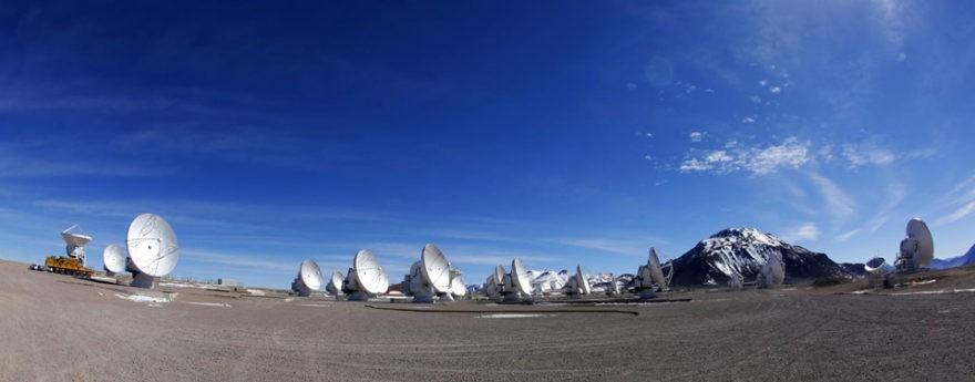

12 Interferometer Two examples: - ALMA - VLA

13 Interferometer Special mention: VLBI Make an interferometer the size of the Earth combine signals from antennas all around Earth Tape record data and combine later off-line or send in real-time over internet


14 Future Many telescopes are upgrading e-merlin, e-vlbi New telescope growing MeerKat, LOFAR, ASKAP
15 Conclusions IT ISA GOOD MOMENT TO DO RADIOASTRONOMY

16 Why we need interferometry? The angular resolution of single dish radio telescope is given by: θ ~ λ/d where: λ = wavelength of the signal received D = telescope diameter For example at 6 cm the Effelsberg telescope (D = 100 m) has a resolution of 2 arcmin.the human eye resolution is 1 arcmin

17 Interferometry The idea is to use an array of separate telescopes working together as a wider single telescope. SINGLE DISH

18 Interferometry The basic idea is to use an array of separate telescopes working together as a wider single telescope. IDEAL INTERFEROMETER

19 Interferometry The basic idea is to use an array of separate telescopes working together as a wider single telescope. REAL INTERFEROMETER

20 Interferometry The idea is to use an array of separate telescopes working together as a wider single telescope. In this way the resolution increases up to: θ ~ λ/bmax where: λ = wavelength of the signal received BMAX = maximum distance of two array telescopes This process is possible by means of the interferometry technique. A radio interferometer measures the coherence of the electric field between the 2 receiving elements. Since the problem of N interferometers can be treated as a defined number of interferometer pairs, the basic of interferometry is to study the simplest case, a two-element narrowband interferometer.
21 Interferometry 2 identical dishes separated by a distance b, called BASELINE. Plane waves from the space reach the two antennae at different time. The output of the voltage measured by the two antenna is the same, with a lags of τg, called GEOMETRIC DELAY. e.g. a geometrical delay of about 1 millisecond is expected for B ~ 300 km The CORRELATOR multiplies the two voltages and averaging in time gives: R = (V2/2)cos(ωτg) i.e. the correlator output depends on the voltages and the geometric delay. This function R varies sinusoidally with the change of source direction in the interferometers frame.
, and ωt is the phase, depending on the source position.")
22 Interferometry These sinusoids are called FRINGES where V2/2 is the amplitude (proportional to the point source flux density S), and ωt is the phase, depending on the source position. This is similar to what happens in Young s experiment with double slits:
23 Interferometry These sinusoids are called FRINGES where V2/2 is the amplitude (proportional to the point source flux density S), and ωt is the phase, depending on the source position. This is similar to what happens in Young s experiment with double slits:
24 Interferometry These sinusoids are called FRINGES where V2/2 is the amplitude (proportional to the point source flux density S), and ωt is the phase, depending on the source position. This is similar to what happens in Young s experiment with double slits:
.")
25 Interferometry These sinusoids are called FRINGES where V2/2 is the amplitude (proportional to the point source flux density S), and ωt is the phase, depending on the source position. If the antennae were isotropic the response function would be a sinusoids spanning the sky, and sensitive to only the Fourier component of the brightness with angular period λ/(b sin θ). A baseline samples only specific spatial frequencies components of the signal emitted: mλ/(b sin θ) (m is an integer number)
.")
26 Interferometry These sinusoids are called FRINGES with V2/2 is the amplitude (proportional to the point source flux density S), and ωt is the phase, depending on the source position. If the antennae were isotropic the response function would be a sinusoids spanning the sky, and sensitive to only the Fourier component of the brightness with angular period λ/(b sin θ). A baseline samples only specific spatial frequencies components of the signal emitted: mλ/(b sin θ) (m is an integer number)
27 Foreword before the Visibility Any real function can be decomposed into an even and odd part: I(x,y) = IE(x,y) + IO(x,y) Such that: IE(-x,-y) = IE(x,y) symmetric function IO(-x,-y) = -IO(x,y) antysimmetric function
28 Foreword before the Visibility Fourier theorem states that any periodic function (of perdio P) or periodic signal can be decomposed into a sum of simple oscillating functions, namely sines and cosines, expressed with: f(x) = Σ [A cos(2πnx/p)+b sin(2πnx/p)] or in complex notation f(x) = Σ Ce i(2πnx/p)
29 Visibility We can treat extended sources as the sum of independent point sources. However, with cosine correlator we are sensitive only to the even part of the intensity emitted. Antennae Position Response Function (Fringes)
30 Visibility We can treat extended sources as the sum of independent point sources. However, with cosine correlator we are sensitive only to the even part of the intensity emitted. Antennae Position Response Function (Fringes)
31 Visibility We can treat extended sources as the sum of independent point sources. However, with cosine correlator we are sensitive only to the even part of the intensity emitted. To detect the odd part we need a sine correlator, usually implemented using a second correlator with a 90 deg phase delay inserted in the output on an antenna. The combination of cosine and sine correlators is called complex correlator, because using the correlation: eiф = cos(ф) + i sin(ф) we can write the total answer of the complex correlators as: V = Rcosine-iRsine V is the COMPLEX VISIBILITY, can be written as: V = Ae-iф A = AMPLITUDE and ф = PHASE - The phase is the offset of the filter that maximizes the total transmitted intensity - The amplitude is the value of this maximal transmitted intensity
32 Visibility The COMPLEX VISIBILITY in the uv plane. Each antenna pairs has its own point in the uv plane, which represents the separation between each pair as seen from the source In this plane each visibility is the integral of the sky brightness T(x,y) in the Fourier space: V(u,v) = T(x,y) e2πi (ux+vy)dx dy

33 Visibility In conclusion the interferometer output is a set ot visibility measurements, done for each baseline This approach introduces new definition of an interferometer: A radio interferometer is an instrument that samples the visibility function, which is the Fourier transform of the sky brightness distribution
. T(x,y) is the inverse Fourier transform of V(u,v). But in reality we have finite sampling of the uv plane T(x,y) must be reconstructed.")
34 Visibility and the sky brightness The possibility to convert visibilites into sky brightness measurements is given by the van Cittert-Zernike Theorem: The visibility V(u,v) is the 2D Fourier transform of the sky brightness T(x,y). T(x,y) is the inverse Fourier transform of V(u,v). But in reality we have finite sampling of the uv plane T(x,y) must be reconstructed. The inverse Fourier transform of the actual finite set of V gives the DIRTY IMAGE
35 Aperture synthesis To increase the point-source response we needs more Fourier components. Taking advantages of the earth rotation we have more interferometers, and we approach to a Gaussian, that correspond to the SYNTHESIZED BEAMS

36 Aperture synthesis As the hearts rotate the uv sampling increases, and the image of the point-source observed becomes a gaussian
37 Aperture synthesis As the hearts rotate the uv sampling increases, and the image of the point-source observed becomes a gaussian

38 Aperture synthesis As the hearts rotate the uv sampling increases, and the image of the point-source observed becomes a gaussian

39 Aperture synthesis As the hearts rotate the uv sampling increases, and the image of the point-source observed becomes a gaussian
40 Aperture synthesis As the hearts rotate the uv sampling increases, and the image of the point-source observed becomes a gaussian
41 Aperture synthesis As the hearts rotate the uv sampling increases, and the image of the point-source observed becomes a gaussian

42 Aperture synthesis As the hearts rotate the uv sampling increases, and the image of the point-source observed becomes a gaussian
43 Aperture synthesis As the hearts rotate the uv sampling increases, and the image of the point-source observed becomes a gaussian
44 Further details: Primary beam (FOV) The field of view of an interferometer, also called PRIMARY BEAM, depends on the single dish diameter: FOV = 1.22 λ/dsd Smaller dish larger FOV then. If the object is larger than the FOV mosaic N.B. = sensitivity decreases with the distance from the image centre
45 Further details: Sensitivity Measurement of visibilities is limited by noise emitted by atmosphere, antenna, ground receivers. The rms noise in a data cube is: with: Tsys = system temperature A = area of each antenna N = number of antennas NP = number of polarizations Δν = bandwidth Δτ = observing time The sensitivity is a strong function of the atmospheric conditions. The troposphere has an effect on the optical depth, the atmospheric emission, and on the demands for calibration
46 Further details: Synthesized beam The angular resolution of the interferometer is the FWHM of the SYNTHESIZED BEAM, and depends on the maximum distance between antennas: θ = λ/bmax Extended configuration smaller angular resolution.
 the diffuse component cannot be recovered.")
47 Further details: Synthesized beam At the same time the maximum recoverable scale depends on the minimum baseline, and since by definition it cannot be less than the antenna diameter (there would be antennas overlap) the diffuse component cannot be recovered. For this reasons ALMA as an ACA and a TP with the goal of recovering this component (NOEMA for example uses the 30 m telescope)
48 Some hint about calibration Once you have your visibilities the next step is to calibrate them. There are 4 main steps to perform: 1 Atmoshperic Phase Correction: to correct for the fluctuations of precipitable water vapor (PWV) 2 Phase calibration, to determine the variations of phase and amplitude with time 3 Bandpass calibration, to correct for different receiver responses during the observations 4 Flux calibration, to convert in the right units the visibilities observed
49 Some hint about Imaging Once you have your calibrated visibility the next step is to do imaging. This process is called deconvolution : You first do a FFT of the interpolated visibilities to get a Dirty Image, then proceed with the CLEANING: - assume the source brightness distribution is a sum of point sources - Fit and subtract the synthesized beam iteratively

50 Some hint about Imaging You first do a FFT of the interpolated visibilities to get a Dirty Image, then proceed with the CLEANING: - assume the source brightness distribution is a sum of point sources - Fit and subtract the synthesized beam iteratively
51 Take Home Messages 1 - Interferometers use an array of separate telescopes working together as a wider single telescope 2 - A radio interferometer measures the coherence of the electric field between the 2 receiving elements 3 - A radio interferometer is an instrument that samples the visibility function, which is the Fourier transform of the sky brightness distribution 4 - The possibility to convert visibilites into sky brightness measurements is given by the van Cittert-Zernike Theorem 5 - The maximum recoverable scale depends on the minimum baseline, and since by definition it cannot be less than the antenna diameter (there would be antennas overlap) the diffuse component cannot be recovered
Radio Interferometry and Aperture Synthesis
 Radio Interferometry and Aperture Synthesis Phil gave a detailed picture of homodyne interferometry Have to combine the light beams physically for interference Imposes many stringent conditions on the
A Crash Course in Radio Astronomy and Interferometry: 2. Aperture Synthesis
 A Crash Course in Radio Astronomy and Interferometry: 2. Aperture Synthesis James Di Francesco National Research Council of Canada North American ALMA Regional Center Victoria (thanks to S. Dougherty,
Fundamentals of radio astronomy
 Fundamentals of radio astronomy Sean Dougherty National Research Council Herzberg Institute for Astrophysics Apologies up front! Broad topic - a lot of ground to cover (the first understatement of the
An Introduction to Radio Astronomy
 An Introduction to Radio Astronomy Bernard F. Burke Massachusetts Institute of Technology and Francis Graham-Smith Jodrell Bank, University of Manchester CAMBRIDGE UNIVERSITY PRESS Contents Preface Acknowledgements
Introduction to Radio Interferometry Jim Braatz (NRAO)
") Introduction to Radio Interferometry Jim Braatz (NRAO) Atacama Large Millimeter/submillimeter Array Expanded Very Large Array Robert C. Byrd Green Bank Telescope Very Long Baseline Array Radio Astronomy
Introduction to Radio Interferometry Jim Braatz (NRAO) Atacama Large Millimeter/submillimeter Array Expanded Very Large Array Robert C. Byrd Green Bank Telescope Very Long Baseline Array Radio Astronomy
An Introduction to Radio Astronomy
 An Introduction to Radio Astronomy Second edition Bernard F. Burke and Francis Graham-Smith CAMBRIDGE UNIVERSITY PRESS Contents Preface to the second edition page x 1 Introduction 1 1.1 The role of radio
Radio Interferometry and VLBI. Aletha de Witt AVN Training 2016
 Radio Interferometry and VLBI Aletha de Witt AVN Training 2016 Radio Interferometry Single element radio telescopes have limited spatial resolution θ = 1.22 λ/d ~ λ/d Resolution of the GBT 100m telescope
Radio Interferometry and ALMA
 Radio Interferometry and ALMA T. L. Wilson ESO 1 PLAN Basics of radio astronomy, especially interferometry ALMA technical details ALMA Science More details in Interferometry Schools such as the one at
Radio Interferometry Fundamentals. John Conway Onsala Space Obs and Nordic ALMA ARC-node
 Radio Interferometry Fundamentals John Conway Onsala Space Obs and Nordic ALMA ARC-node So far discussed only single dish radio/mm obs Resolution λ/d, for D=20m, is 30 at mm-wavelengths and 30 (diameter
The Australia Telescope. The Australia Telescope National Facility. Why is it a National Facility? Who uses the AT? Ray Norris CSIRO ATNF
 The Australia Telescope National Facility The Australia Telescope Ray Norris CSIRO ATNF Why is it a National Facility? Funded by the federal government (through CSIRO) Provides radio-astronomical facilities
Principles of Interferometry. Hans-Rainer Klöckner IMPRS Black Board Lectures 2014
 Principles of Interferometry Hans-Rainer Klöckner IMPRS Black Board Lectures 2014 acknowledgement Mike Garrett lectures James Di Francesco crash course lectures NAASC Lecture 5 calibration image reconstruction
How do you make an image of an object?
 How do you make an image of an object? Use a camera to take a picture! But what if the object is hidden?...or invisible to the human eye?...or too far away to see enough detail? Build instruments that
Advanced Topic in Astrophysics Lecture 1 Radio Astronomy - Antennas & Imaging
 Advanced Topic in Astrophysics Lecture 1 Radio Astronomy - Antennas & Imaging Course Structure Modules Module 1, lectures 1-6 (Lister Staveley-Smith, Richard Dodson, Maria Rioja) Mon Wed Fri 1pm weeks
CMB interferometry (20 April 2012)
") CMB interferometry (20 April 2012) Clive Dickinson (Jodrell Bank CfA, U. Manchester) CMB power spectrum measurements We have come a long way in just a few years! Interferometers have made a big impact
CMB interferometry (20 April 2012) Clive Dickinson (Jodrell Bank CfA, U. Manchester) CMB power spectrum measurements We have come a long way in just a few years! Interferometers have made a big impact
Outline. Mm-Wave Interferometry. Why do we care about mm/submm? Star-forming galaxies in the early universe. Dust emission in our Galaxy
 Outline 2 Mm-Wave Interferometry Debra Shepherd & Claire Chandler Why a special lecture on mm interferometry? Everything about interferometry is more difficult at high frequencies Some problems are unique
E-MERLIN and EVN/e-VLBI Capabilities, Issues & Requirements
 E-MERLIN and EVN/e-VLBI Capabilities, Issues & Requirements e-merlin: capabilities, expectations, issues EVN/e-VLBI: capabilities, development Requirements Achieving sensitivity Dealing with bandwidth,
THEORY OF INTERFEROMETRY AND APERTURE SYNTHESIS
 THEORY OF INTERFEROMETRY AND APERTURE SYNTHESIS ABSTRACT. The basics of interferometry are covered in these lectures. We first discuss a simple interferometer and show that the output is proportional to
Radio sources. P. Charlot Laboratoire d Astrophysique de Bordeaux
 Radio sources Laboratoire d Astrophysique de Bordeaux Outline Introduction Continuum and spectral line emission processes The radio sky: galactic and extragalactic History of radioastronomy The first 50
Future Radio Interferometers
 Future Radio Interferometers Jim Ulvestad National Radio Astronomy Observatory Radio Interferometer Status in 2012 ALMA Covers much of 80 GHz-1 THz band, with collecting area of about 50% of VLA, for a
Astronomical Experiments for the Chang E-2 Project
 Astronomical Experiments for the Chang E-2 Project Maohai Huang 1, Xiaojun Jiang 1, and Yihua Yan 1 1 National Astronomical Observatories, Chinese Academy of Sciences, 20A Datun Road,Chaoyang District,
Deconvolving Primary Beam Patterns from SKA Images
 SKA memo 103, 14 aug 2008 Deconvolving Primary Beam Patterns from SKA Images Melvyn Wright & Stuartt Corder University of California, Berkeley, & Caltech, Pasadena, CA. ABSTRACT In this memo we present
=> most distant, high redshift Universe!? Consortium of international partners
 LOFAR LOw Frequency Array => most distant, high redshift Universe!? Consortium of international partners Dutch ASTRON USA Haystack Observatory (MIT) USA Naval Research Lab `best site = WA Novel `technology
Journal Club Presentation on The BIMA Survey of Nearby Galaxies. I. The Radial Distribution of CO Emission in Spiral Galaxies by Regan et al.
 Journal Club Presentation on The BIMA Survey of Nearby Galaxies. I. The Radial Distribution of CO Emission in Spiral Galaxies by Regan et al. ApJ, 561:218-237, 2001 Nov 1 1 Fun With Acronyms BIMA Berkely
Can we do this science with SKA1-mid?
 Can we do this science with SKA1-mid? Let s start with the baseline design SKA1-mid expected to go up to 3.05 GHz Proposed array configuration: 133 dishes in ~1km core, +64 dishes out to 4 km, +57 antennas
Millimeter Antenna Calibration
 Millimeter Antenna Calibration 9 th IRAM Millimeter Interferometry School 10-14 October 2016 Michael Bremer, IRAM Grenoble The beam (or: where does an antenna look?) How and where to build a mm telescope
Transient Cosmic Phenomena and their Influence on the Design of the SKA Radio Telescope
 Transient Cosmic Phenomena and their Influence on the Design of the SKA Radio Telescope Research Review Curtin Institute of Radio Astronomy 5 May 2009 ToC Parameter space Discovering phenomena ASKAP &
Radio interferometry in astronomy: a view into the XXI century
 Radio interferometry in astronomy: a view into the XXI century Lecture 1 Introduction and basics of (radio) interferometry Leonid Gurvits Joint Institute for VLBI in Europe, Dwingeloo, The Netherlands
Fourier phase analysis in radio-interferometry
 Fourier phase analysis in radio-interferometry François Levrier Ecole Normale Supérieure de Paris In collaboration with François Viallefond Observatoire de Paris Edith Falgarone Ecole Normale Supérieure
Wide-Field Imaging: I
 Wide-Field Imaging: I S. Bhatnagar NRAO, Socorro Twelfth Synthesis Imaging Workshop 010 June 8-15 Wide-field imaging What do we mean by wide-field imaging W-Term: D Fourier transform approximation breaks
Short-Spacings Correction From the Single-Dish Perspective
 Short-Spacings Correction From the Single-Dish Perspective Snezana Stanimirovic & Tam Helfer (UC Berkeley) Breath and depth of combining interferometer and single-dish data A recipe for observing extended
Information Field Theory. Torsten Enßlin MPI for Astrophysics Ludwig Maximilian University Munich
 Information Field Theory Torsten Enßlin MPI for Astrophysics Ludwig Maximilian University Munich Information Field Theory signal field: degrees of freedom data set: finite additional information needed
Lecture 9: Indirect Imaging 2. Two-Element Interferometer. Van Cittert-Zernike Theorem. Aperture Synthesis Imaging. Outline
 Lecture 9: Indirect Imaging 2 Outline 1 Two-Element Interferometer 2 Van Cittert-Zernike Theorem 3 Aperture Synthesis Imaging Cygnus A at 6 cm Image courtesy of NRAO/AUI Very Large Array (VLA), New Mexico,
New calibration sources for very long baseline interferometry in the 1.4-GHz band
 New calibration sources for very long baseline interferometry in the 1.4-GHz band M K Hailemariam 1,2, M F Bietenholz 2, A de Witt 2, R S Booth 1 1 Department of Physics, University of Pretoria, South
Future radio galaxy surveys
 Future radio galaxy surveys Phil Bull JPL/Caltech Quick overview Radio telescopes are now becoming sensitive enough to perform surveys of 107 109 galaxies out to high z 2 main types of survey from the
Radio Astronomy module
 Radio Astronomy module Contact tony@ska.ac.za Notes: NRAO Essential radio astronomy course: http://www.cv.nrao.edu/course/astr534/era.shtml See also http://www.haystack.mit.edu/ edu/undergrad/materials/ra_tutorial.html
Energy Sources of the Far IR Emission of M33
 Energy Sources of the Far IR Emission of M33 Hinz, Reike et al., ApJ 154: S259 265 (2004). Presented by James Ledoux 24 µm 70 µm 160 µm Slide 1 M33 Properties Distance 840kpc = 2.7 Mlyr (1'' ~ 4 pc) Also
BINGO simulations and updates on the performance of. the instrument
 BINGO simulations and updates on the performance of BINGO telescope the instrument M.-A. Bigot-Sazy BINGO collaboration Paris 21cm Intensity Mapping Workshop June 2014 21cm signal Observed sky Credit:
Very Long Baseline Interferometry (VLBI) Wei Dou Tutor: Jianfeng Zhou
 Wei Dou Tutor: Jianfeng Zhou") Very Long Baseline Interferometry (VLBI) Wei Dou Tutor: Jianfeng Zhou 2017 03-16 Content Introduction to interferometry and VLBI VLBA (Very Long Baseline Array) Why VLBI In optics, airy disk is a point
Very Long Baseline Interferometry (VLBI) Wei Dou Tutor: Jianfeng Zhou 2017 03-16 Content Introduction to interferometry and VLBI VLBA (Very Long Baseline Array) Why VLBI In optics, airy disk is a point
Interferometer Circuits. Professor David H. Staelin
 Interferometer Circuits Professor David H. Staelin Massachusetts Institute of Technology Lec18.5-1 Basic Aperture Synthesis Equation Recall: E( ) E r,t,t E E λ = λ { } Ι ( Ψ ) E R E τ φ τ Ψ,t,T E A Ψ 2
Interference, Diffraction and Fourier Theory. ATI 2014 Lecture 02! Keller and Kenworthy
 Interference, Diffraction and Fourier Theory ATI 2014 Lecture 02! Keller and Kenworthy The three major branches of optics Geometrical Optics Light travels as straight rays Physical Optics Light can be
The data model. Panos Labropoulos. Kapteyn Instituut
 The data model Panos Labropoulos " Challenges The actual 21-cm signal is several times weaker than the foregrounds and sits below the telescope noise Foregrounds: galactic and extragalactic (polarization?)
Lecture 9: Speckle Interferometry. Full-Aperture Interferometry. Labeyrie Technique. Knox-Thompson Technique. Bispectrum Technique
 Lecture 9: Speckle Interferometry Outline 1 Full-Aperture Interferometry 2 Labeyrie Technique 3 Knox-Thompson Technique 4 Bispectrum Technique 5 Differential Speckle Imaging 6 Phase-Diverse Speckle Imaging
Imaging with the SKA: Comparison to other future major instruments
 1 Introduction Imaging with the SKA: Comparison to other future major instruments A.P. Lobanov Max-Planck Institut für Radioastronomie, Bonn, Germany The Square Kilometer Array is going to become operational
Radio interferometry at millimetre and sub-millimetre wavelengths
 Radio interferometry at millimetre and sub-millimetre wavelengths Bojan Nikolic 1 & Frédéric Gueth 2 1 Cavendish Laboratory/Kavli Institute for Cosmology University of Cambridge 2 Institut de Radioastronomie
Imaging Capability of the LWA Phase II
 1 Introduction Imaging Capability of the LWA Phase II Aaron Cohen Naval Research Laboratory, Code 7213, Washington, DC 2375 aaron.cohen@nrl.navy.mil December 2, 24 The LWA Phase I will consist of a single
Continuum Observing. Continuum Emission and Single Dishes
 July 11, 2005 NAIC/NRAO Single-dish Summer School Continuum Observing Jim Condon Continuum Emission and Single Dishes Continuum sources produce steady, broadband noise So do receiver noise and drift, atmospheric
e-vlbi Radio interferometers How does VLBI work? What science do we do with VLBI? How has the technology changed? Advantages of e-vlbi e-astronomy
 e-vlbi Radio interferometers How does VLBI work? What science do we do with VLBI? How has the technology changed? Advantages of e-vlbi e-astronomy Simple interferometer In a simple interferometer, two
Peter Teuben (U. Maryland)
") ALMA Study Total Power Map to Visibilities (TP2VIS) Joint-Deconvolution of ALMA 12m, 7m & TP Array Data Peter Teuben (U. Maryland) Jin Koda (Stony Brook/NAOJ/JAO); Tsuyoshi Sawada (NAOJ/JAO); Adele Plunkett
ALMA Study Total Power Map to Visibilities (TP2VIS) Joint-Deconvolution of ALMA 12m, 7m & TP Array Data Peter Teuben (U. Maryland) Jin Koda (Stony Brook/NAOJ/JAO); Tsuyoshi Sawada (NAOJ/JAO); Adele Plunkett
Mapping the Galaxy using hydrogen
 The Swedish contribution to EU-HOU: A Hands-On Radio Astronomy exercise Mapping the Galaxy using hydrogen Daniel Johansson Christer Andersson Outline Introduction to radio astronomy Onsala Space Observatory
Apertif. Paolo Serra. Tom Oosterloo (PI) Marc Verheijen (PI) Laurens Bakker George Heald Wim van Cappellen Marianna Ivashina
 Marc Verheijen (PI) Laurens Bakker George Heald Wim van Cappellen Marianna Ivashina") Netherlands Institute for Radio Astronomy Apertif Tom Oosterloo (PI) Marc Verheijen (PI) Laurens Bakker George Heald Wim van Cappellen Marianna Ivashina ASTRON is part of the Netherlands Organisation for
Netherlands Institute for Radio Astronomy Apertif Tom Oosterloo (PI) Marc Verheijen (PI) Laurens Bakker George Heald Wim van Cappellen Marianna Ivashina ASTRON is part of the Netherlands Organisation for
Low-frequency radio astronomy and wide-field imaging
 Low-frequency radio astronomy and wide-field imaging James Miller-Jones (NRAO Charlottesville/Curtin University) ITN 215212: Black Hole Universe Many slides taken from NRAO Synthesis Imaging Workshop (Tracy
Introduction to Radioastronomy
 Introduction to Radioastronomy J.Köppen joachim.koppen@astro.unistra.fr http://astro.u-strasbg.fr/~koppen/jkhome.html Overview History, Discoveries, Sources Equipment and Observing Techniques ISU Radiotelescopes
What is this radio interferometry business anyway? Basics of interferometry Calibration Imaging principles Detectability Using simulations
 What is this radio interferometry business anyway? Basics of interferometry Calibration Imaging principles Detectability Using simulations Interferometry Antenna locations Earth rotation aperture synthesis
Next Generation VLA Memo. 41 Initial Imaging Tests of the Spiral Configuration. C.L. Carilli, A. Erickson March 21, 2018
 Next Generation VLA Memo. 41 Initial Imaging Tests of the Spiral Configuration C.L. Carilli, A. Erickson March 21, 2018 Abstract We investigate the imaging performance of the Spiral214 array in the context
Sky Mapping: Continuum and polarization surveys with single-dish telescopes
 1.4 GHz Sky Mapping: Continuum and polarization surveys with single-dish telescopes Wolfgang Reich Max-Planck-Institut für Radioastronomie (Bonn) wreich@mpifr-bonn.mpg.de What is a Survey? A Survey is
Interferometry for pedestrians - a very brief introduction and basic concepts 1
 Interferometry for pedestrians - a very brief introduction and basic concepts 1 Erik Bertram 1 Article concerning the lecture Perspektiven Moderner Astrophysik, Lecturer: Priv.- Doz. Dr. Silke Britzen
Max-Planck-Institut für Radioastronomie, Bonn Istituto di Radioastronomia - INAF, Bologna
 RadioNet3 & SKA Franco Mantovani Project Scientist RadioNet3 Max-Planck-Institut für Radioastronomie, Bonn Istituto di Radioastronomia - INAF, Bologna RadioNet3 Advanced Radio Astronomy in Europe www.radionet-eu.org
Galactic Structure Mapping through 21cm Hyperfine Transition Line
 Galactic Structure Mapping through 21cm Hyperfine Transition Line Henry Shackleton MIT Department of Physics (Dated: May 14, 2017) Using a Small Radio Telescope (SRT), we measure electromagnetic radiation
Chapter 9: Interferometry and Aperture Synthesis
 Chapter 9: Interferometry and Aperture Synthesis 9.1 Introduction How can we get higher angular resolution than the simple full width at half maximum of the Airy function,/d? One answer is indicated in
Image Reconstruction Algorithms for 2D Aperture Synthesis Radiometers
 Image Reconstruction Algorithms for 2D Aperture Synthesis Radiometers E. Anterrieu 1 and A. Camps 2 1 Dept. Signal, Image & Instrumentation Laboratoire d Astrophysique de Toulouse-Tarbes Université de
Imaging applications of Statistical Optics
 Imaging applications of Statistical Optics Monday Radio Astronomy Michelson Stellar Interferometry Coherence Imaging Rotational Shear Interferometer (RSI) Wednesday Optical Coherence Tomography (OCT) 03/14/05
Optical interferometry: problems and practice
 Outline Optical interferometry: problems and practice Chris Haniff Aims. What is an interferometer? Fundamental differences between optical and radio. Implementation at optical wavelengths. Conclusions.
Large Field of View Radio Astronomy; relevant for many KSP s
 Large Field of View Radio Astronomy; relevant for many KSP s SKA Key Science Drivers ORIGINS Probing the Dark Ages When & how were the first stars formed? Cosmology and Galaxy Evolution Galaxies, Dark
SCIENTIFIC CASES FOR RECEIVERS UNDER DEVELOPMENT (OR UNDER EVALUATION)
") SCIENTIFIC CASES FOR RECEIVERS UNDER DEVELOPMENT (OR UNDER EVALUATION) C.STANGHELLINI (INAF-IRA) Part I Infrastructure 1 Main characteristics and status of the Italian radio telescopes 2 Back-ends, opacity
SCIENTIFIC CASES FOR RECEIVERS UNDER DEVELOPMENT (OR UNDER EVALUATION) C.STANGHELLINI (INAF-IRA) Part I Infrastructure 1 Main characteristics and status of the Italian radio telescopes 2 Back-ends, opacity
RADIO ASTRONOMY II. QPR No. 83. Academic and Research Staff
 II. RADIO ASTRONOMY Academic and Research Staff Prof. A. H. Barrett Prof. L. B. Lenoir Dr. S. H. Zisk Prof. B. F. Burke Prof. D. H. Staelin Patricia P. Crowther Prof. M. Loewenthal E. R. Jensen Graduate
Remote Sensing & Image-making
 Remote Sensing & Image-making Physics Urvashi Rau New Mexico Tech, National Radio Astronomy Observatory, Socorro, NM, USA Instrumentation Jan 15 2009 Computing (1) What is Remote Sensing? (2) Types of
Spectral Resolution in Interferometry
 Spectral Resolution in Interferometry Christopher Tycner Michelson Postdoctoral Fellow @ U. S. Naval Observatory Flagstaff Station Outline Spectral Resolution in Interferometry Implementation Benefits
Non-Imaging Data Analysis
 Outline 2 Non-Imaging Data Analysis Greg Taylor Based on the original lecture by T.J. Pearson Introduction Inspecting visibility data Model fitting Some applications Superluminal motion Gamma-ray bursts
Methanol masers and their environment at high resolution
 Mon. Not. R. Astron. Soc. 300, 1131 1157 (1998) Methanol masers and their environment at high resolution C. J. Phillips, 1 R. P. Norris, 2 S. P. Ellingsen 1 and P. M. McCulloch 1 1 Department of Physics,
Applications of Statistical Optics
 Applications of Statistical Optics Radio Astronomy Michelson Stellar Interferometry Rotational Shear Interferometer (RSI) Optical Coherence Tomography (OCT) Apps of Stat Optics p-1 Radio Telescope (Very
Single-dish antenna at (sub)mm wavelengths
mm wavelengths") Single-dish antenna at (sub)mm wavelengths P. Hily-Blant Institut de Planétologie et d Astrophysique de Grenoble Université Joseph Fourier October 15, 2012 Introduction A single-dish antenna Spectral surveys
Single-dish antenna at (sub)mm wavelengths P. Hily-Blant Institut de Planétologie et d Astrophysique de Grenoble Université Joseph Fourier October 15, 2012 Introduction A single-dish antenna Spectral surveys
Interferometry and Aperture Synthesis
 Chapter 2 Interferometry and Aperture Synthesis A. P. Rao 2.1 Introduction Radio astronomy is the study of the sky at radio wavelengths. While optical astronomy has been a field of study from time immemorial,
Ay 20 Basic Astronomy and the Galaxy Problem Set 2
 Ay 20 Basic Astronomy and the Galaxy Problem Set 2 October 19, 2008 1 Angular resolutions of radio and other telescopes Angular resolution for a circular aperture is given by the formula, θ min = 1.22λ
1mm VLBI Call for Proposals: Cycle 4
 1mm VLBI Call for Proposals: Cycle 4 22 March 2016 Introduction The National Radio Astronomy Observatory (NRAO) invites proposals for 1mm Very Long Baseline Interferometry (VLBI) using the phased output
The Search for Extraterrestrial Intelligence (SETI) Director Jodrell Bank Centre for Astrophysics
 Director Jodrell Bank Centre for Astrophysics") The Search for Extraterrestrial Intelligence (SETI) Mike Garrett e-merlin & EVN in Sir Bernard Chair, Prof. of Astrophysics. SKA eralovell workshop Director Jodrell Bank Centre for Astrophysics - Introduction.
The Search for Extraterrestrial Intelligence (SETI) Mike Garrett e-merlin & EVN in Sir Bernard Chair, Prof. of Astrophysics. SKA eralovell workshop Director Jodrell Bank Centre for Astrophysics - Introduction.
On Calibration of ALMA s Solar Observations
 On Calibration of ALMA s Solar Observations M.A. Holdaway National Radio Astronomy Observatory 949 N. Cherry Ave. Tucson, AZ 85721-0655 email: mholdawa@nrao.edu January 4, 2007 Abstract 1 Introduction
Radio Transient Surveys with The Allen Telescope Array & the SKA. Geoffrey C Bower (UC Berkeley)
") Radio Transient Surveys with The Allen Telescope Array & the SKA Geoffrey C Bower (UC Berkeley) Transient Science is Exploding New Phenomena An Obscured Radio Supernova in M82 Discovered serendipitously
Radio Transient Surveys with The Allen Telescope Array & the SKA Geoffrey C Bower (UC Berkeley) Transient Science is Exploding New Phenomena An Obscured Radio Supernova in M82 Discovered serendipitously
Lab 2 Working with the X-Band Interferometer
 Lab 2 Working with the X-Band Interferometer Abhimat Krishna Gautam 6 March 2012 ABSTRACT Lab 2 performed experiments with the X-Band Interferometer consisting of two dishes placed along an East-West axis.
Multiwavelength Astronomy (things that have called my attention over the years)
") Multiwavelength Astronomy (things that have called my attention over the years) Luis F. Rodríguez, CRyA, UNAM, Morelia Until a few decades ago, an observational astronomer could survive knowing only about
Multiwavelength Astronomy (things that have called my attention over the years) Luis F. Rodríguez, CRyA, UNAM, Morelia Until a few decades ago, an observational astronomer could survive knowing only about
Centimeter Wave Star Formation Studies in the Galaxy from Radio Sky Surveys
 Centimeter Wave Star Formation Studies in the Galaxy from Radio Sky Surveys W. J. Welch Radio Astronomy Laboratory, Depts of EECS and Astronomy University of California Berkeley, CA 94720 Tel: (510) 643-6543
Photons. Observational Astronomy 2018 Part 1 Prof. S.C. Trager
 Photons Observational Astronomy 2018 Part 1 Prof. S.C. Trager Wavelengths, frequencies, and energies of photons Recall that λν=c, where λ is the wavelength of a photon, ν is its frequency, and c is the
9/19/ Basic Properties of Light and Matter. Chapter 5: Light: The Cosmic Messenger. What is light? Lecture Outline
 Lecture Outline 5.1 Basic Properties of Light and Matter Chapter 5: Light: The Cosmic Messenger Our goals for learning: What is light? What is matter? How do light and matter interact? What is light? Light
Interferometry of Solar System Objects
 Interferometry of Solar System Objects Bryan Butler National Radio Astronomy Observatory Atacama Large Millimeter/submillimeter Array Expanded Very Large Array Robert C. Byrd Green Bank Telescope Very
Planning an interferometer observation
 2nd ERIS, Bonn, September 2007 Planning an interferometer observation T. Venturi Istituto di Radioastronomia, Bologna, INAF tventuri@ira.inaf.it Outline I. Planning an experiment/preparing a proposal II.
History of Radio Telescopes
 History of Radio Telescopes A Technology Saga Triggered by Serendipity Paul Vanden Bout National Radio Astronomy Observatory Karl Jansky - 1933 Jansky discovered radiation at λ14.6m (20.5 MHz) that moved
MURCHISON WIDEFIELD ARRAY
 MURCHISON WIDEFIELD ARRAY STEPS TOWARDS OBSERVING THE EPOCH OF RE-IONIZATION Ravi Subrahmanyan Raman Research Institute INDIA View from Earth: cosmic radio background from cosmological evolution in gas
ALMA Memo 373 Relative Pointing Sensitivity at 30 and 90 GHz for the ALMA Test Interferometer M.A. Holdaway and Jeff Mangum National Radio Astronomy O
 ALMA Memo 373 Relative Pointing Sensitivity at 30 and 90 GHz for the ALMA Test Interferometer M.A. Holdaway and Jeff Mangum National Radio Astronomy Observatory 949 N. Cherry Ave. Tucson, AZ 85721-0655
Introduction to Radio Interferometers Mike Garrett (ASTRON/Swinburne)
") Introduction to Radio Interferometers Mike Garrett (ASTRON/Swinburne) ERIS School - Bonn - Sep 11, 2007. Overview of Lecture Early radio astronomy what makes radio astronomy "special"! Radio Interferometry
Introduction to Radio Interferometers Mike Garrett (ASTRON/Swinburne) ERIS School - Bonn - Sep 11, 2007. Overview of Lecture Early radio astronomy what makes radio astronomy "special"! Radio Interferometry
Apertif - the focal-plane array system for the WSRT
 WIDEFIELD SCIENCE AND TECHNOLOGY FOR THE SKA SKADS CONFERENCE 2009 S.A. Torchinsky, A. van Ardenne, T. van den Brink-Havinga, A. van Es, A.J. Faulkner (eds.) 4-6 November 2009, Chateau de Limelette, Belgium
History of Radioastronomy from 1800 to 2007
 History of Radioastronomy from 1800 to 2007 (a personal selection) Steve Torchinsky Observatoire de Paris History of radio astronomy, Steve Torchinsky Goutelas, 4 June 2007 1 Herschel discovers invisible
Submillimetre astronomy
 Sep. 20 2012 Spectral line submillimetre observations Observations in the submillimetre wavelengths are in principle not different from those made at millimetre wavelengths. There are however, three significant
Dr. Cran Lucas. Shreveport-Bossier Astronomical Society & Shreveport Amateur Radio Association KG5NMF
 Amateur Radio Astronomy Dr. Cran Lucas Shreveport-Bossier Astronomical Society & Shreveport Amateur Radio Association KG5NMF Outline Radio Astronomy Basics Radio Astronomy History Radio Astronomy Telescopes
High (Angular) Resolution Astronomy
 Resolution Astronomy") High (Angular) Resolution Astronomy http://www.mrao.cam.ac.uk/ bn204/ mailto:b.nikolic@mrao.cam.ac.uk Astrophysics Group, Cavendish Laboratory, University of Cambridge January 2012 Outline Science Drivers
High (Angular) Resolution Astronomy http://www.mrao.cam.ac.uk/ bn204/ mailto:b.nikolic@mrao.cam.ac.uk Astrophysics Group, Cavendish Laboratory, University of Cambridge January 2012 Outline Science Drivers
Chapter 6 Light and Telescopes
 Chapter 6 Light and Telescopes Guidepost In the early chapters of this book, you looked at the sky the way ancient astronomers did, with the unaided eye. In chapter 4, you got a glimpse through Galileo
Light Pollution. Atmospheric Seeing. Seeing Through the Atmosphere. Atmospheric Absorption of Light
 Lec 8: 2 FEB 2012 ASTR 130 - Introductory Astronomy II (Chapter 6) LAST TIME - Optics and Telescopes Basic Functions of a Telescope Reflecting v. Refracting Affects of the Atmosphere TODAY Modern Astronomical
Optical interferometry a gentle introduction to the theory
 Optical interferometry a gentle introduction to the theory Chris Haniff Astrophysics Group, Cavendish Laboratory, Madingley Road, Cambridge, CB3 0HE, UK Motivation A Uninterested: I m here for the holiday.
Spectral survey analysis: the WEEDS package
 Spectral survey analysis: the WEEDS package P. Hily-Blant & S. Maret Institute for Panetary science and Astrophysics of Grenoble (IPAG) University Joseph Fourier Collaborators: J. Pety, S. Bardeau, E.
tf, oscillating with wavelength λ, then a distant observer will measure an electric field given by the Kirchhoff diffraction integral, Equation 12.
 6 Lecture, 26 October 999 6. The van Cittert - Zernike theorem and radio interferometers The largest single-dish radio telescopes have diffraction-limited resolution no better than tens of arcseconds,
Analysis of the Hydrogen Gas Distribution in the Galaxy HIZSS 3
 Analysis of the Hydrogen Gas Distribution in the Galaxy HIZSS 3 Lance Edens Advisor: Dr. Patricia Henning Honors Thesis University of New Mexico Department of Physics and Astronomy April 21, 2006 Abstract
Phase-Referencing and the Atmosphere
 Phase-Referencing and the Atmosphere Francoise Delplancke Outline: Basic principle of phase-referencing Atmospheric / astrophysical limitations Phase-referencing requirements: Practical problems: dispersion