ALagrangiananalysisofatwo-dimensionalairfoil with vortex shedding
|
|
|
- Milton Turner
- 5 years ago
- Views:
Transcription
1 IOP PUBLISHING JOURNAL OF PHYSICS A: MATHEMATICAL AND THEORETICAL J. Phys. A: Math. Theor. 41 (2008) (22pp) doi: / /41/34/ ALagrangiananalysisofatwo-dimensionalairfoil with vortex shedding Doug Lipinski, Blake Cardwell and Kamran Mohseni Department of Aerospace Engineering Sciences, University of Colorado, Boulder, CO , USA Received 6 December 2007, in final form 22 May 2008 Published 11 August 2008 Online at stacks.iop.org/jphysa/41/ Abstract Using invariant material manifolds and flow topology, the flow behavior and structure of flow around a two-dimensional Eppler 387 airfoil is examined with an emphasis on vortex shedding and the time-dependent reattachment profile. The examination focuses on low Reynolds number (Re = ) flow at several angles of attack. Using specialized software, we identify invariant manifolds in the flow and use these structures to illuminate the process of vortex formation and the periodic behavior of the reattachment profile. Our analysis concludes with a topological view of the flow, including fixed points and a discussion of phase plots and the frequency spectrum of several key points in the flow. The behavior of invariant manifolds directly relates to the flow topology and illuminates some aspects seen in phase space during vortex shedding. Furthermore, it highlights the reattachment behavior in ways not seen before. PACS numbers: g, j, y, Jj (Some figures in this article are in colour only in the electronic version) 1. Introduction 1.1. Background Micro aerial vehicles (MAVs) have recently become a topic of significant effort in scientific communities. The unique challenges and opportunities that MAV technology offers have resulted in increased interest in topics such as flexible wing, flapping wing and low Reynolds number aerodynamics. This paper specifically targets the behavior of low Reynolds number reattachment and vortex shedding for potential MAV applications. There exists a multitude of /08/ $ IOP Publishing Ltd Printed in the UK 1
2 Figure 1. Classical diagram of separation bubble structure [1]. previous work regarding the behavior and properties of separation and vortex shedding. Early work in the field of separation was highlighted by Hornton in 1968 [1] whointroducedthe now well-known time averaged laminar separation bubble model. Continuing work focused on behavior behind a backward facing step [2, 3], pressure-induced separation [4]andseparation behind airfoils [5 7]. These studies utilized velocity fields (both numerical and experimental), vorticity contours and streamlines to observe the behavior of vortex shedding. The result of this work is a detailed understanding of the separation profile, vortex pairing and vortex shedding, and their effect on airfoil performance. The discussion regarding reattachment behavior, on the other hand, has previously been limited to time-averaged results. Thus several issues remain to be investigated, including the time-dependent behavior of reattachment, the detailed structure of fluid mixing and how the shed vortices form. Understanding this behavior may lead to advances in flow actuation theory by highlighting key structures and times in the flow including structures below and in front of the airfoil. Although the behavior of unstable manifolds over an airfoil without vortex shedding has recently been investigated [8], this investigation will examine the behavior of both stable and unstable manifolds associated with reattachment and vortex shedding behind an airfoil. Although the separation profile is well understood, little is known about the timedependent reattachment profile. Reattachment is equally important since the size of the separation bubble is largely determined by the reattachment point. Manipulation of the separation bubble is critically important to the aerodynamic performance of a vehicle. This is achieved through various methods aimed at manipulating the separation or reattachment points. One of the goals of the present study is to provide insight into how the reattachment profile behaves by utilizing invariant material manifolds. By exploring the formation of shed vortices, this study will aim to elucidate critical moments and locations in the formation process which may be particularly useful for manipulation Material manifolds The steady laminar separation bubble is defined by the dividing streamline shown in figure 1 [5]. In a time-averaged view, the material flux across the profile is zero. For our setup, low Re 2
![Figure 2. Time-averaged velocity and streamlines for low Reynolds number flow. α = 4,Re = 60 000, Eppler 387 airfoil [10]. Figure 3. Representative vorticity map for low Reynolds number flow.](/docs-images/89/98894718/images/3-0.jpg "α = 4,Re = 60 000, Eppler 387 airfoil [10]. flow over an airfoil at α = 4,thetime-averagedvelocityfieldandstreamlinesareshownin figure 2.")
 canbeused,butvorticitycontoursdo not have the inherent zero mass flux property that we desire.")
3 Figure 2. Time-averaged velocity and streamlines for low Reynolds number flow. α = 4,Re = , Eppler 387 airfoil [10]. Figure 3. Representative vorticity map for low Reynolds number flow. α = 4,Re = , Eppler 387 airfoil [10]. flow over an airfoil at α = 4,thetime-averagedvelocityfieldandstreamlinesareshownin figure 2. Investigatinghowthisbubblebehavesinrealtimeontheotherhandhasproven difficult, in part due to the complications involved in identifying the reattachment lines. Traditional flow maps such as the vorticity (figure 3) canbeused,butvorticitycontoursdo not have the inherent zero mass flux property that we desire. Instantaneous streamlines are somewhat better, but show little detail in flow structures. Invariant material manifolds, on the other hand, delineate clear transport barriers and separate the flow into distinct regions [9]. These manifolds may be either repelling or attracting material manifolds, but in either case, the flux across the manifolds is negligible, and this is the property we require to visualize the separation bubble in real time. The repelling material lines, also known as stable manifolds are responsible for the stretching of passive tracer groups normal to the manifold while attracting material lines, also known as unstable manifolds are responsible for the stretching of tracer groups tangent to the manifold [11]. When an unstable manifold is attached to a wall, fluid particles are drawn from the near wall region and ejected along the manifold path. Thus the separation profile of the flow should correspond with an unstable manifold. The reverse is true for stable manifolds attaching to a wall; their profile represents the reattachment line. For the remainder of this manuscript we will provide a brief overview of Lagrangian coherent structures as material manifolds and observe the behavior of the invariant manifolds. We will also demonstrate the relationship between particle motion and the manifold profiles. We will also explore the behavior of fixed points and flow topology. Finally, we will examine the phase plane behavior of several points in the flow. We find excellent agreement between all these methods of analysis and conclude with a detailed understanding of the flow structure and behavior during vortex shedding. 3
4 2. Lagrangian coherent structures 2.1. LCS and invariant manifolds Lagrangian coherent structures (LCS) were first introduced by Haller et al [12]in2000. Haller defines LCS as material lines with locally the longest or shortest stability or instability time. In dynamical systems theory, such structures are referred to as stable and unstable manifolds and will hereafter be referred to as such. Our research objective is to locate and analyze these manifolds, and for that analysis LCS theory is a useful tool. In practical applications, LCS are defined as ridges of the finite time Lyapunov exponent (FTLE) field [8]. These ridges represent the material lines or manifolds in the flow which are characterized by very low flux across the profile. The manifolds are unique and time dependent and due to their invariance their interaction with one another is largely responsible for fluid mixing Calculation of LCS For our calculation of FTLE fields, we will closely follow the procedure set forth by Shadden et al [8]. It should be noted that FTLE fields are not the only method for identifying LCS [13], FTLE was chosen for this study because it is well suited to a discrete velocity field defined on a finite time interval. Following Shadden et al [8], once a velocity field has been defined (numerically, experimentally or analytically), the region to be analyzed is seeded with a dense mesh of passive fluid tracers. The tracers are advected with the flow for an integration time τ and the Cauchy Green deformation tensor,, iscalculatedforeachpointbasedonthe deformation of the tracer mesh. The FTLE is then defined in terms of the maximal stretching based on as σt τ 0 (x) = 1 τ ln λ max ( ), (1) where λ max ( ) is the maximal eigenvalue of. Stableandunstablemanifoldsarethendefined as ridges in the FTLE field with τ>0forstablemanifoldsandτ<0forunstablemanifolds. For this study, the velocity field was given by the results of a computational fluid dynamics (CFD) simulation for the flow around the airfoil. For details of the numerical procedure for the CFD simulation see [14]. The FTLE field was calculated using a code developed for this purpose. 3. Procedures In this simulation, two-dimensional flow over an Eppler 387 airfoil is examined. The free stream velocity is m s 1 and the Reynolds number is Re = This wing type has been previously used for MAVs [15] andre = is in the typical range of MAV operation [16]. The run was performed in a non-dimensional mode, defining the free stream velocity as 1 unit length/unit time. A unit length is defined as the chord length, and a unit time therefore is the chord length divided by the freestream velocity. The results showed a vortex formation shedding frequency of approximately 2.4 shedding cycles per unit time. A time step of t = unit time is used for accuracy, but to conserve memory only every 8th timestep is stored. Therefore, the time step for the exported data files is t = time units. The partitioned, unstructured velocity field files are then compiled by our FTLE program, creating node and element connection lists, and initializing search protocols. The desired area for calculation of FTLE values is specified by the user s designation of the drifter mesh. The software uses an alternating digital tree algorithm [17] to search the domain for 4
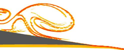
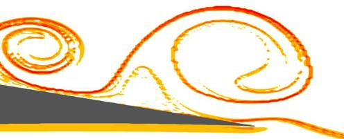
5 the element containing each indexed drifter, the velocity is interpolated onto this point using shape functions, and the location and velocity information are stored for future steps. The indexed drifters are advected forward in time using a 4th order Runge Kutta scheme. In this simulation, 240 velocity time steps were analyzed, for α = 2, 4 and 6. The Cartesian mesh of drifters covered the domain 1 x 1.5, 0.5 y 0.5, with a uniform grid spacing of x = y = units. This grid spacing was necessary to capture the fine detailed structures in the wake region and to ensure the accuracy of the manifold calculations. The accurate calculation of LCS structures requires that the grid spacing be small [11]. The integration time was set to τ =0.72 time units to optimize the appearance of the desired flow structures. Longer integration times reveal more detail, but the important structures become obscured by unimportant features while shorter integration times fail to reveal the desired level of detail. 4. Behavior of manifolds 4.1. Unstable manifolds Contour plots of the backward time (τ = 0.72) FTLE field showing unstable manifold structures are shown in figure 4 for a full shedding cycle. Major recurring coherent structures in the flow are marked by U1 U7 in this figure. These manifolds are represented by welldefined ridges in the FTLE contour plot, shown as dark lines (online version: red and orange lines). Figures 5, 6, 7 and 8 show magnified views of the most interesting regions. In figure 4, thefarthestupstreamunstablemanifold(labeledu1)whichattachestotheairfoilis the separation point in the flow. This manifold is well defined and is observed to be largely time invariant. Although the separation point has been studied extensively in the past, it remains the source of some confusion in the case of unsteady flows. Haller has shown that for incompressible flow, the effective separation point is just the point of zero mean skin friction on the airfoil [18]. In the case that the point of zero skin friction is time invariant, the separation point is also time invariant. In previous analysis of this flow, this point has been observed to be time invariant (see figure 3.6 of [10]) and the separation point is therefore stationary. Underneath this manifold is a region of stalled flow, known as the separated shear layer, which will be examined in more detail shortly. Moving downstream we note four prominent manifolds as shown in figure 6. ThemanifoldsU2andU3 (figure6(a)) coincide with forming vortices and have a well-defined structure which forms an attachment between the vortices. Another manifold, U4 (figure 6(c)), on the airfoil surface is very strong and will eventually become a part of the shed vortex. This manifold is associated with the secondary induced vortex. Finally, the manifold immediately upstream of U4 will be shown to be responsible for transporting many fluid particles upstream into the stalled flow region. Note, as time progresses, that several of these coherent structures collide and connect in several places, and as vortices are shed from the trailing edge new manifolds evolve upstream to form the next set of vortices. Downstream of the trailing edge, there are two distinct FTLE ridges which should be noted. The most prominent structure is the connection between the counter-rotating shed vortices (U7) as seen in figure 4(a). This manifold is one of the strongest to appear anywhere in the flow field, and shows that there exists a well-defined separation between the two shed vortices and the surrounding flow that is not clear in plots of vorticity or streamlines. In fact, U2 (figure 4(a)) is the same manifold as U7, but for the next pair of vortices which have yet to be shed. The second is another strong manifold attached to the trailing edge of the airfoil (U6, figures 4(a) and8(a)). As a vortex is shed, this manifold is stretched and wrapped into 5
6 (a) time= 0.00 (b) time= 0.06 (c) time= 0.12 (d) time= 0.18 (e) time= 0.24 ( f )time= 0.30 (g) time= 0.36 (h) time= 0.42 (i) time= 0.48 (j) time= 0.54 (k) time= 0.60 (l) time= 0.66 Figure 4. Contour plots of FTLE over airfoil, U1 U7 are the major recurring structures in the flow, online version shows these ridges in red and orange. U1 Figure 5. LCS profile at separation point. the core of the vortex. This deformation of U6 occurs near the trailing edge, but does not destroy the structure of U6. Instead, the remnants of the manifold become attached to the 6
 time=0.78 Figure 6.")
 time=0.84 (b) time=0.96 (c) time=1.08 (d) time=1.")


7 U1 U3 U2 U4,U5 (a) time=0.42 (b) time=0.66 U1 U3 U4 U2 U5 (c) time=0.66 (d) time=0.78 Figure 6. Unstable manifold behavior along upper surface of airfoil during vortex shedding. U3 U4 U2 U6 (a) time=0.84 (b) time=0.96 (c) time=1.08 (d) time=1.20 Figure 7. Unstable manifold behavior at the trailing edge of an airfoil during vortex shedding. leading shed vortex and a new connection is established. This behavior is in actually part of asurprisingprocesswhichcorrespondswithfluidentrainmentfrombelowtheairfoilintothe shed vortices. As the second vortex in the shed pair leaves the trailing edge we can see a single coherent structure linking the trailing edge of the airfoil to the past two shed vortex pairs. The connection between shed vortices begins to weaken as they move farther downstream. Introducing fluid tracers to the flow field allows us to examine the interactions between the unstable manifolds and particle motion. Drifters are initially located at x = 0 and for each grouping, 91 drifters are released and advected forward in time. In figure 9,drifters have been released at times 0.24 time units apart; each new set of particles is represented by a new symbol and color. 7

8 U7 U6 (a) time=1.26 (b )time=1.38 (c) time=1.50 (d) time=1.62 Figure 8. Unstable manifold behavior past the trailing edge of an airfoil during vortex shedding. As expected, most of the drifters eventually find their way onto or very near one of the unstable manifolds in the flow. This is independent of when the drifters are released; the release frequency was chosen to enhance clarity. Instead, this is due to the fact that unstable manifolds are attracting material lines. Attracting material lines are responsible for localized thinning and folding of the flow as well as stretching in the direction tangent to the manifold [12]. In fact, Haller and Yuan [12]showintheirpaperthatagroupofdenselypacked passive tracers involved in mixing can show the locations of attracting material lines by simply watching how the particles begin grouping and stretching to form regions and lines of very dense and very sparse concentrations of particles. This behavior in the airfoil wake region provides evidence that the unstable manifolds identified really behave as attracting material lines. Further evidence may be found in figure 10 in which we see the time progression of a grouping of particles approaching manifold U2. The particles in figure 10 are pushed up by the secondary induced vortex (manifold U4) on the surface of the airfoil and impact approximately normal to the line U2 at point A1 in figure 10(c). This group of fluid tracers is split apart by the manifold, some to be entrained into the vortex core, others to continue moving upstream. Those particles which are not captured by the vortex move upstream toward the stalled flow region as shown in figure 11. Note that while traveling upstream a great percentage of these drifters are concentrated near manifold lines. Additionally, it is observed that those particles closest to the manifolds appear to move upstream more quickly than those not near amanifold.thisbehaviorisexpectedperinancet al [19]. The fluid particles which continue moving upstream into the stalled flow region are transported there along manifold U5. This manifold repeatedly regenerates, moves upstream and dissolves in the stalled flow region, leaving the particles there. The correlation between manifold behavior and particle behavior offers opportunities for flow manipulation. Since the manifolds dictate where particles may go, it is enough to manipulate the manifold s shape to change the flow structure. If the location of an unstable manifold could be established in real time, small manipulations of the manifold at the airfoil surface may have significant effects on particles along the manifold profile, but far away from the airfoil surface. 8
 time=0.30 (g) time=0.36 (h) time=0.42 Figure 9.")

, group 2: (online: purple), group 3: (online:")


9 (a) time=0.00 (b )time=0.06 (c) time=0.12 (d) time=0.18 (e) time=0.24 (f) time=0.30 (g) time=0.36 (h) time=0.42 Figure 9. FTLE contour plot with passive fluid tracers overlaid. Five groups of 91 drifters released with frequency beginning at t = Group 1: (online: white), group 2: (online: purple), group 3: (online: pink), group 4: (online: green), group 5: (online: brown) Angle of attack and vortex pairing So far we have focused on behavior over an airfoil with 4 angle of attack. Unsurprisingly, the angle of attack has a noticeable impact on manifold behavior. For this study we have examined the behavior at 2,4 and 6 angles of attack. Figure 12 shows the comparison of these three angles of attack for a typical point in their vortex shedding cycle. Note that the structures share common traits in all three cases. As expected, the separated region begins farther upstream as α is increased. A closer inspection of the manifolds shows another trend. The secondary induced vortex, which we will shortly label as V5, appears to be more energetic as the angle of attack increases. For our purposes it was determined that the six degree angle of attack 9

 time=0.84 (d) time=0.96 Figure 11.")


10 (a) time=0.36 (b )time=0.42 (c) time=0.48 (d) time=0.54 Figure 10. Drifters from group 3 incident upon LCS line U2. U1 U3 U1 U3 U2 U2 U4,U5 U5 U4 (a) time=0.60 (b )time=0.72 U1 U3 U2 U1 U3 U2 U5 U4 U4 (c) time=0.84 (d) time=0.96 Figure 11. Drifters from all groups demonstrating the effect of LCS U4 and U5 on transporting drifters upstream in the stalled flow region. presents the most illustrative cases for vortex pairing. Thus, for the following sections the focus of our study will shift to α = 6. Figure 13 shows the time evolution of the unstable manifolds at α = 6. The similarities to α = 4 case are numerous, but here we will focus on the behavior of individual vortices. Using traditional flow maps (e.g. vorticity), the individual vortices become indistinguishable from each other once they are paired. Using material manifolds, we can track the remnants of the individual vortices for a much longer time. Figure 13 shows the unstable manifold representation of vortex pairing. Beginning in figure 13(a), we track the formation and movement of four distinct regions (V1 V4) that eventually form the large scale vortex shed from the trailing edge. Even though there is extensive deformation of the individual structures 10

 (b) (c) (d) Figure 13.")

11 Figure 12. Comparison of the LCS manifolds at different angles of attack. (a) (b) (c) (d) Figure 13. Contour plots of backward time FTLE over airfoil representing the unstable manifolds, α = 6,Re =


12 (a) (b) (c) (d ) Figure 14. Contour plots of forward time FTLE over airfoil representing the stable manifolds, α = 6,Re = throughout formation, by using material manifolds we can track the remnants of each until it nears the trailing edge at which point the manifolds begin to lose their definition as seen in figure 13(d). As the vortex leaves the trailing edge, two additional regions are picked up, V5 and V6, figure 13(b). Vortex V5 is the secondary induced vortex from the airfoil surface, and V6 is the counter rotating tip vortex which contains material from below the airfoil s surface. V6 gets paired with the shed vortex and they move downstream as a pair. Vortex V5 is picked up from the top surface as the vortices approach the trailing edge, and gets rolled around the top boundary of the vortex pair to finally settle downstream of the main vortices as shown in figure 13(c). The rest of the behavior for the unstable manifolds at six degree angle of attack is consistent with the behavior examined previously at α = Stable manifolds Our discussion of unstable manifolds was initially motivated by the presence of an unstable manifold which delineates the separation profile. To further our understanding of the separation bubble, we now shift to an analysis of stable manifolds for a 6 airfoil under the same conditions, which we expect to reveal the reattachment profile. Figure 14 shows the time evolution of the 12
13 stable manifolds over the airfoil. Note that while we can identify the large scale structures, most of the manifolds in this view do not look like the familiar vortices we may expect. This is because calculating the stable manifolds involves using our future knowledge of how the flow field will behave. If we focus on the reattachment behavior we see that there is a clear reattachment point found at location L1 in figure 14(a). The manifold attached to this point, S4, is clearly a ridge in the FTLE field, but it is not as strong of a ridge as we might expect the reattachment profile to display. In fact, it is clearly not the dominant feature in figure 14(a). This is due to the shedding behavior of the flow which leads to a periodic dissolving and reforming of the reattachment manifold. In figures 14(b) and(c), manifold S4 weakens, but S3 transforms into a new shape, forming a new reattachment manifold which is visible in figure 14(c), but has an unexpected shape. By figure 14(d), the expected reattachment profile as seen in time-averaged separation bubbles has reappeared. Manifold S4 weakens just as vortex V4 (figure 13) joinsthepaired vortices as seen in section 4.1. Thissignifiesthecompletionofthevortexpairingatwhich point the newly formed vortex begins moving downstream. There are two additional structures that are very interesting. Manifolds S5 and S6 appear as weak, but distinct ridges above and below the airfoil in figure 14(a). Figure 14(b)showsthat manifold S5 has been pulled around the shedding vortex and eventually manifolds S5 and S6 leave the trailing edge together, merging to create manifold S7. The appearance of manifold S7 coincides with the formation of the roll up vortex seen in section 4.1. Thefluidparticles contained inside manifolds S5 and S6 are the same fluid particles which will eventually make up the rolled up vortex. This reveals unexpected structure to the flow underneath the airfoil. From a flow control perspective, it suggests that utilizing flow control on the lower surface and targeting this manifold could cause changes in the vortex shedding structure. Also, it shows that the flow which eventually forms the roll-up vortex exists as two distinct and intact groups well ahead of the point where the roll up occurs. In fact, manifold S5 first appears upstream of the leading edge, while manifold S6 forms just downstream of the stagnation point. These observations have been further examined by Cardwell and Mohseni [20] Stable and unstable paired manifolds Together the stable and unstable manifolds are known to define regions or lobes of distinct particle mixing [9]. Thus, for a complete understanding of the flow topology we need to combine the two to learn how they interact. Combining the stable and unstable manifolds will reveal exact vortex boundaries (as demonstrated in [21]), locations where entrainment is possible, and the time-dependent profile of the separation bubble. Figure 15 shows the limited time evolution of the two manifolds. In this case, we have plotted the more familiar structure of the unstable manifolds as a contour map of the FTLE values, and then overlaid a clipped contour map of the stable manifolds and colored these black. The result is a complete map of the manifolds involved in vortex shedding. As expected, the manifolds often meet and sometimes overlap. This demonstrates that flow boundaries are a combination of stable and unstable manifolds just as Shadden et al [21] have shown for a vortex ring. Note that the shed vortex in figure 15(a), largely defined by the unstable manifolds, is closed by the stable manifold. The most interesting and complicated behavior occurs inside the separation bubble. This behavior is more clearly shown in figure 16 where the domain has been restricted. In this figure, the impact of manifold S3 is revealed. Beginning during vortex formation, the S3 manifold isolates the formation region from all flow but the inlet, where the new vortices will draw their strength from. S3 also separates the just forming vortices from the vortices which 13


14 (a) (b) Figure 15. Contour plots of forward and backward FTLE over airfoil representing the stable (black) and unstable (colored) manifolds, α = 6,Re = are peeling off from the separation bubble to move downstream. As time evolves, manifolds S2 and S3 take on more definition as S4 is eroding. Soon S3 has begun to lose some of its defining shape, while the S2 manifold begins to acquire these same shapes. This is the evolution of manifolds in action. S2, S3 and S4 are really the same periodically forming manifolds which separate pairs of vortices from one another. Although we can affix labels to the manifolds at a given instant of time, they will continuously evolve and soon no longer contain any of their initially defining features. Perhaps one of the most interesting insights that the pairing of stable and unstable manifolds gives us is a defined boundary for the separation bubble which we can watch evolve and change during a shedding cycle. Though it may be difficult to interpret in some places due to its dynamic nature, the region near the airfoil bounded by the stable and unstable LCS manifolds is the separation bubble. The fact that this bubble may have openings in it is expected since the traditional definition of a separation bubble as having zero mass flux is based on a time-averaged view. In this case we are watching the separated region deform in real time. Since there is zero flux across the manifolds shown flow into and out of the separation bubble must come through the gaps in these manifolds during the shedding process. 5. Flow topology To gain additional information about the vortex shedding and reattachment, we now focus on atopologicaloverviewoftheflowasdeterminedbyanalyzingstreamlinesintheflow. See figure 17 for an overview of three representative times in the development of the flow topology. First, we verify the viability of these topologies by checking that the fixed points satisfy the relationship developed by Hunt et al [22]fortherelativenumberoffixedpointsintheflow: ) E H ( E ) ( H = 1 n, (2) where E and H represent four-way elliptic and hyperbolic fixed points, E and H represent three-way elliptic and hyperbolic fixed points and n is the connectivity of the region, in our 14
 and(b) having E = 6,E = 0,H = 2andH = 10. The topology in figure 17(c) addsanextraellipticand hyperbolic fixed point.")
 transitions to 17(b), H1 and E1 move toward the rear of the separation bubble and the vortex centered on point E2 is ready to be shed.")

15 (a) (b ) (c) (d ) Figure 16. Contour plots of forward and backward FTLE over airfoil representing the stable (black) and unstable (gray or colored online) manifolds, α = 6,Re = 60, 000. case n = 2. All three topologies satisfy this relationship with figure 17(a) and(b) having E = 6,E = 0,H = 2andH = 10. The topology in figure 17(c) addsanextraellipticand hyperbolic fixed point. It is interesting to follow the development of fixed points in the flow. Figure 17(a)showsa separation bubble with a vortex moving toward the trailing edge of the airfoil. As figure 17(a) transitions to 17(b), H1 and E1 move toward the rear of the separation bubble and the vortex centered on point E2 is ready to be shed. As figure 17(b) transitions to 17(c), a reverse saddlenode bifurcation occurs as points H1 and E1 collide, destroying each other and separating a new vortex from the separation bubble. At the same time, the three way hyperbolic points, H2 and H3 collide and separate from the airfoil s surface, creating a new four-way hyperbolic point just below the shed vortex. The collision of H2 and H3 and subsequent separation from the airfoil represents a fundamental change in the topology of the flow as a vortex is shed. Finally, a new elliptic fixed point forms near the airfoil s surface in the upstream portion of the separation bubble. This fixed point forms as the flow here pulls away from the airfoil s surface and also creates two new three-way hyperbolic fixed points. After all of this, figure 17(c) transitionsbackto17(a) asthefixedpointsintheshedvortexmerge,canceling 15


16 (a) (b) (c) Figure 17. Flow topology of vortex shedding at three representative times. designate elliptic fixed points, designate hyperbolic fixed points. Figure 18. Fixed points in the flow, overlaid on top of stable and unstable manifolds. Online version shows unstable manifolds in red, stable manifolds are overlaid in gray. Hyperbolic fixed points are gray squares (green online) ( ), elliptic fixed points are black squares (dark blue online) ( ). each other in another reverse saddle-node bifurcation and the newly formed vortex which has just split from the separation bubble begins moving down the airfoil. These processes closely match what we previously observed in the invariant manifolds. The saddle-node bifurcation involving H1 and E1 corresponds with the manifold previously labeled U4 in section 4.1 beginning to push upward, separating the developing vortex from the separation bubble. At the same time, the reattachment profile is reforming upstream. The new reattachment profile lies along manifold S3 as seen in figure 14(a) whichisseenin figure 17(c)asthebackoftheseparationbubble. Fixed points in the flow also closely relate to the coherent structures we have seen previously. Figure 18 shows the position of fixed points in the flow overlaid with the stable and unstable manifolds. Note that the hyperbolic fixed points largely correspond with intersections between the stable and unstable manifolds and the elliptic fixed points occur inside vortices 16
17 Figure 19. Locations where phase portraits were calculated. Points R1 R5 (red online) lie on a streamline above the airfoil, points G1 G4 (green online) lie along the upstream vertical line near the separation point, points P1 P10 (purple online) lie just above the airfoil s surface in the vortex formation region and points B1 B4 (blue online) lie in the downstream vertical line in the vortex formation region. Figure 20. Phase portrait of red points along streamline shown in figure 19. identified by these manifolds. This correspondence is indicative of the fact that invariant manifolds convey information similar to the flow topology, but with the additional property of zero flux through the manifolds. 6. Phase plots There are two main ways of looking at any dynamical system, in physical space or phase space. Up to this point, we have focused on the physical space of our system, so to finalize our analysis of the vortex shedding process we now turn to a discussion of phase portraits and the dominant frequencies at several representative points in the flow. Figure 19 shows the locations of 24 points where the velocity variations were tracked. Points R1 R5 (red online) lie on a streamline above the airfoil, points G1 G4 (green online) lie along the upstream vertical line near the separation point, points P1 P10 (purple online) lie about chord lengths above the airfoil s surface in the vortex formation region and points B1 B4 (blue online) lie in the downstream vertical line in the vortex formation region. Each set of points has been numbered 17
18 Figure 21. Phase plots of the purple points located along the surface of the airfoil where vortex formation occurs, as shown in figure 19. Thex-axis is u-velocity and the y-axis is v-velocity. and plotted in figures The varying amplitude seen in the phase plot corresponding to the streamline points in figure 20 shows how the energy increases as the flow passes over the airfoil and then begins to decrease downstream. Points R1 and R2 show very little velocity disturbance upstream of the separation point. Moving past the separation point we see the disturbances begin to build at point R3, but are somewhat chaotic. Points R4 and R5 lie in the region where vortices are well formed and because of this exhibit highly periodic behavior. An analysis of the frequency spectrums reveals a dominant frequency corresponding to the vortex shedding frequency and a strong secondary frequency at twice this rate (see figure 24). In fact, all points downstream of P3 except B4 show the same two dominant frequencies in their spectrum (more on this later). The secondary frequency appears because the main vortex is formed by two initially distinct vortices which pair with one another. This results in the observed frequency doubling. If we turn our attention to the points along the airfoil surface, figure 21 shows how the variations grow and have well-defined periodic structures. This is of particular interest because these points are located near the surface of the airfoil and if the velocity can be measured in real time, it would be possible to determine precisely where in the vortex shedding process the flow is, providing feedback for flow actuation methods. Points P1 and P2, although in 18
19 Figure 22. Phase portrait of green points along upstream vertical cross-section of flow shown in figure 19. Figure 23. Phase portrait of blue points along downstream vertical cross-section of flow shown in figure 19. the separation bubble, lack the secondary frequency seen in the downstream points due to their location in the dead air region upstream of the first elliptic fixed point seen in figure 17. As expected, the G1 G4 (green online) points, figure 22, show very little fluctuation in the flow since they are located near the separation point. Contrastingly, if we look at the B1 B4 19
20 5 Frequency spectrum 3.5 Frequency spectrum R5 3 B4 Normalized Amplitude R4 R3 R2 Normalized Amplitude B3 B R Frequency (Hz) 3.5 (a) Points along the streamline (red online) Frequency spectrum Frequency (Hz) 10 B1 (b) Points along the downstream vertical line (blue online) Frequency spectrum Normalized Amplitude G4 G3 G2 G Frequency (Hz) (c) Normalized Amplitude Points along the upstream vertical line (green online) P Frequency (Hz) (d) P10 P9 P8 P7 P6 P5 P4 P3 P2 Points along the airfoil surface (purple online) Figure 24. Frequency spectra for the points shown in figure 19. Eachgroup(red,green,blueand purple in the online version) has been normalized by the maximum amplitude occurring in this group. (blue online) points, figure 23, we see large variations in the flow velocity because we are now looking at the wake region, figure 23. Interestingly,ifwecompareall24points,wefind only three phase plots (R4, R5 and B2) which have larger fluctuations in the vertical velocity than the horizontal velocity. These points all lie on or near the streamline in the vortex wake region. This is indicative of the vortex formation and roll-up process that we have illustrated throughout this paper. The phase analysis presented here provides several interesting incites. First, points in the vortex formation and wake region can be expected to exhibit highly periodic behavior with a 20
21 dominant frequency matching that of the vortex shedding and a strong secondary frequency of twice this value. The phase plots for the points along the airfoil surface (figure 21) readily demonstrate the presence of a secondary harmonic by the knots seen in the phase plots, but afrequencyspectrumanalysisrevealsthatthissecondaryharmonicispresentinalmostall points downstream of P3. As discussed by Xilin et al [23], the presence of the subharmonic characterizes this flow as having vortex pairing and roll up, exactly as we have seen in our analysis using coherent structures. We attribute the absence of the secondary frequency at B4 to the distance of B4 from the airfoil surface. The roll-up process does not reach this point so only the primary frequency appears. Finally, flow actuation techniques may be able to take advantage of the highly periodic nature of the flow in the vortex shedding region by identifying key times for actuation. 7. Conclusion In this study we have investigated the flow topology for low Reynolds number, unsteady flow behind an airfoil. We have provided a comprehensive study of the flow behavior in physical space and phase space, and seen good agreement between all areas of flow analysis. We have documented the evolution of the invariant manifolds during vortex shedding and observed the time-dependent motion of the reattachment profile. We have found that the reattachment profile periodically develops and propagates downstream to be shed with a vortex as a new reattachment profile forms upstream. The invariant manifolds also allow the identification of individual vortices which pair together and form a larger vortex which will be shed from the airfoil. The flow topology and motion of the fixed points are also examined. We find for vortex shedding what others have seen in a number of flows, that the motion of fixed points is related to the behavior of invariant manifolds. Finally, the phase plot behavior of a number of representative points is examined. It is noted that the velocity phase plot behavior in the shedding region is highly periodic. Knowing this, it is suggested that this velocity pattern can be used as a flow control feedback mechanism to identify the current stage of vortex shedding. The end result of this investigation is an improved picture of the vortex shedding process, one which may lead to further insights. Acknowledgments The authors would like to acknowledge the support for this investigation through an AFOSR grant from Computational Mathematics group managed by Dr F Fahroo. The authors would also like to acknowledge the developers of ManGen, Francois Lekien and Chad Coulliette [24], and Shawn Shadden [8]. References [1] Hornton H P 1968 Laminar separation bubbles in two and three-dimensional incompressible flow PhD Thesis University of London [2] Abbot D E and Kline S J 1962 Experimental investigations of subsonic turbulent flow over single and double backward-facing steps Trans. ASME D [3] Goldstein R J, Eriksen V L, Olson R M and Eckert E R G 1970 Laminar separation, reattachment, and transition of the flow over a downstream-facing step Trans. ASME D [4] Pauley L, Moin P and Reynolds W C 1990 The structure of two-dimensional separation J. Fluid Mech [5] O Meara M M and Mueller T J 1987 Laminar separation bubble characteristics on an airfoil at low Reynolds numbers AIAA J
22 [6] Muti Lin J C and Pauley L L 1996 Low-Reynolds-number separation on an airfoil AIAA J [7] Yuan W, Xu H, Khalid M and Rasespiel R 2006 A parametric study of LES on laminar-turbulent transitional flows past an airfoil Int. J. Comput. Fluid Dyn [8] Shadden S C, Lekien F and Marsden J E 2005 Definition and properties of Lagrangian coherent structures from finite-time Lyapunov exponents in two-dimensional aperiodic flows Physica D [9] Rom-Kedar V and Wiggins S 1990 Transport in two-dimensional maps Arch. Ration. Mech. Anal [10] Hall J 2007 Low Reynolds number aerodynamics for Micro Aerial Vehicles Master s Thesis University of Colorado (Boulder, CO) [11] Haller G 2002 Lagrangian coherent structures from approximate velocity data Phys. Fluids [12] Haller G and Yuan G 2000 Lagrangian coherent structures and mixing in two-dimensional turbulence Physica D [13] Boffetta G, Lacorata G, Redaelli G and Vulpiani A 2001 Detecting barriers to transport: a review of different techniques Physica D [14] Sahin M, Hall J, Mohseni K and Hillewaert K 2008 Direct numerical simulation of separated low-reynolds number flows around an Eppler 387 airfoil (AIAA paper AIAA , Reno, NV, 7 10 Jan. 2008) 46th AIAA Aerospace Sciences Meeting and Exhibit [15] Gyllhem D, Mohseni K, Lawrence D and Geuzaine P 2005 Numerical simulation of flow around the Colorado micro aerial vehicle (AIAA paper , American Institute of Aeronautics and Astronautics) 35th AIAA Fluid Dynamics Conf. and Exhibit (Toronto, Canada, 6 9 June) [16] Mueller T J 1999 Aerodynamic measurements at low Reynolds numbers for fixed wing micro-air vehicles Development and Operation of UAVs for Military and Civil Applications (VKI, Belgium, Sept ) [17] Bonet J and Peraire J 1990 An alternating digital tree (adt) algorithm for 3d geometric searching and intersection problems Int. J. Numer. Methods Eng [18] Haller G 2004 Exact theory of unsteady separation for two-dimensional flows J. Fluid Mech [19] Inanc T, Shadden S C and Marsden J E 2005 Optimal trajectory generation in ocean flows American Control Conf. pp [20] Cardwell B and Mohseni K 2008 Vortex shedding over two-dimensional airfoil: where do the particles come from? AIAA J [21] Shadden S C, Dabiri J O and Marsden J E 2006 Lagrangian analysis of fluid transport in empirical vortex ring flows Phys. Fluids [22] Hunt J C R, Abell C J, Peterka J A and Woo H 1978 Kinematical studies of the flows around free or surfacemounted obstacles; applying topology to flow visualization J. Fluid Mech [23] Xilin X, Weiwei M and Huiliang Z 2003 Coherent structures in countercurrent axisymmetric shear flows Acta Mech. Sin [24] Lekien F, Coulliette C, Mariano A J, Ryan E H, Shay L K, Haller G and Marsden J E 2005 Pollution release tied to invariant manifolds: a case study for the coast of Florida Physica D
Lagrangian Coherent Structures (LCS)
") Lagrangian Coherent Structures (LCS) CDS 140b - Spring 2012 May 15, 2012 ofarrell@cds.caltech.edu A time-dependent dynamical system ẋ (t; t 0, x 0 )=v(x(t;,t 0, x 0 ),t) x(t 0 ; t 0, x 0 )=x 0 t 2 I R
Lagrangian Coherent Structures (LCS) CDS 140b - Spring 2012 May 15, 2012 ofarrell@cds.caltech.edu A time-dependent dynamical system ẋ (t; t 0, x 0 )=v(x(t;,t 0, x 0 ),t) x(t 0 ; t 0, x 0 )=x 0 t 2 I R
Fluid transport and coherent structures of translating and flapping wings
 Manuscript submitted to Chaos for special issue on Lagrangian Coherent Structures Fluid transport and coherent structures of translating and flapping wings Jeff D. Eldredge and Kwitae Chong Mechanical
Fuel-efficient navigation in complex flows
 2008 American Control Conference Westin Seattle Hotel, Seattle, Washington, USA June 11-13, 2008 WeB16.5 Fuel-efficient navigation in complex flows Carmine Senatore and Shane D. Ross Abstract In realistic
Active Control of Separated Cascade Flow
 Chapter 5 Active Control of Separated Cascade Flow In this chapter, the possibility of active control using a synthetic jet applied to an unconventional axial stator-rotor arrangement is investigated.
Part II: Lagrangian Visualization
 Tutorial: Visualization of Time-Varying Vector Fields Part II: Lagrangian Visualization Filip Sadlo VISUS Universität Stuttgart Germany Overview Part I: Vortices Part II: Vector Field Topology Part I:
Lagrangian Coherent Structures: applications to living systems. Bradly Alicea
 Lagrangian Coherent Structures: applications to living systems Bradly Alicea http://www.msu.edu/~aliceabr Introduction: basic scientific problem Q: How can we quantify emergent structures? Use Lagrangian
SIMULATION OF THREE-DIMENSIONAL INCOMPRESSIBLE CAVITY FLOWS
 ICAS 2000 CONGRESS SIMULATION OF THREE-DIMENSIONAL INCOMPRESSIBLE CAVITY FLOWS H Yao, R K Cooper, and S Raghunathan School of Aeronautical Engineering The Queen s University of Belfast, Belfast BT7 1NN,
Department of Mechanical Engineering
 Department of Mechanical Engineering AMEE401 / AUTO400 Aerodynamics Instructor: Marios M. Fyrillas Email: eng.fm@fit.ac.cy HOMEWORK ASSIGNMENT #2 QUESTION 1 Clearly there are two mechanisms responsible
Time-Dependent Invariant Manifolds Theory and Computation
 Time-Dependent Invariant Manifolds Theory and Computation Cole Lepine June 1, 2007 Abstract Due to the complex nature of dynamical systems, there are many tools that are used to understand the nature of
On the aeroacoustic tonal noise generation mechanism of a sharp-edged. plate
 On the aeroacoustic tonal noise generation mechanism of a sharp-edged plate Danielle J. Moreau, Laura A. Brooks and Con J. Doolan School of Mechanical Engineering, The University of Adelaide, South Australia,
INFLUENCE OF ACOUSTIC EXCITATION ON AIRFOIL PERFORMANCE AT LOW REYNOLDS NUMBERS
 ICAS 2002 CONGRESS INFLUENCE OF ACOUSTIC EXCITATION ON AIRFOIL PERFORMANCE AT LOW REYNOLDS NUMBERS S. Yarusevych*, J.G. Kawall** and P. Sullivan* *Department of Mechanical and Industrial Engineering, University
WALL ROUGHNESS EFFECTS ON SHOCK BOUNDARY LAYER INTERACTION FLOWS
 ISSN (Online) : 2319-8753 ISSN (Print) : 2347-6710 International Journal of Innovative Research in Science, Engineering and Technology An ISO 3297: 2007 Certified Organization, Volume 2, Special Issue
NUMERICAL INVESTIGATION OF THE FLOW OVER A GOLF BALL IN THE SUBCRITICAL AND SUPERCRITICAL REGIMES
 NUMERICAL INVESTIGATION OF THE FLOW OVER A GOLF BALL IN THE SUBCRITICAL AND SUPERCRITICAL REGIMES Clinton Smith 1, Nikolaos Beratlis 2, Elias Balaras 2, Kyle Squires 1, and Masaya Tsunoda 3 ABSTRACT Direct
Chapter 5 Phenomena of laminar-turbulent boundary layer transition (including free shear layers)
") Chapter 5 Phenomena of laminar-turbulent boundary layer transition (including free shear layers) T-S Leu May. 3, 2018 Chapter 5: Phenomena of laminar-turbulent boundary layer transition (including free
Chapter 5 Phenomena of laminar-turbulent boundary layer transition (including free shear layers) T-S Leu May. 3, 2018 Chapter 5: Phenomena of laminar-turbulent boundary layer transition (including free
Numerical study of battle damaged two-dimensional wings
 Advances in Fluid Mechanics IX 141 Numerical study of battle damaged two-dimensional wings S. Djellal, T. Azzam, M. Djellab & K. Lakkaichi Fluid Mechanics Laboratory Polytechnical School Bordj El Bahri,
Geometry of unsteady fluid transport during fluid structure interactions
 J. Fluid Mech. (2007), vol. 589, pp. 125 145. c 2007 Cambridge University Press doi:10.1017/s0022112007007872 Printed in the United Kingdom 125 Geometry of unsteady fluid transport during fluid structure
SENSITIVITY ANALYSIS OF THE FACTORS AFFECTING FORCE GENERATION BY WING FLAPPING MOTION
 Proceedings of the ASME 2013 International Mechanical Engineering Congress and Exposition IMECE2013 November 15-21, 2013, San Diego, California, USA IMECE2013-65472 SENSITIVITY ANALYSIS OF THE FACTORS
Implicit Large Eddy Simulation of Transitional Flow over a SD7003 Wing Using High-order Spectral Difference Method
 40th Fluid Dynamics Conference and Exhibit 28 June - 1 July 2010, Chicago, Illinois AIAA 2010-4442 Implicit Large Eddy Simulation of Transitional Flow over a SD7003 Wing Using High-order Spectral Difference
Effects of Free-Stream Vorticity on the Blasius Boundary Layer
 17 th Australasian Fluid Mechanics Conference Auckland, New Zealand 5-9 December 2010 Effects of Free-Stream Vorticity on the Boundary Layer D.A. Pook, J.H. Watmuff School of Aerospace, Mechanical & Manufacturing
Numerical Investigation of the Fluid Flow around and Past a Circular Cylinder by Ansys Simulation
 , pp.49-58 http://dx.doi.org/10.1457/ijast.016.9.06 Numerical Investigation of the Fluid Flow around and Past a Circular Cylinder by Ansys Simulation Mojtaba Daneshi Department of Mechanical Engineering,
Lecture-4. Flow Past Immersed Bodies
 Lecture-4 Flow Past Immersed Bodies Learning objectives After completing this lecture, you should be able to: Identify and discuss the features of external flow Explain the fundamental characteristics
A Computational Investigation of a Turbulent Flow Over a Backward Facing Step with OpenFOAM
 206 9th International Conference on Developments in esystems Engineering A Computational Investigation of a Turbulent Flow Over a Backward Facing Step with OpenFOAM Hayder Al-Jelawy, Stefan Kaczmarczyk
Proceedings of the 4th Joint US-European Fluids Engineering Division Summer Meeting ASME-FEDSM2014 August 3-7, 2014, Chicago, Illinois, USA
 Proceedings of the 4th Joint US-European Fluids Engineering Division Summer Meeting ASME-FEDSM4 August 3-7, 4, Chicago, Illinois, USA FEDSM4-38 SUPPRESSION OF UNSTEADY VORTEX SHEDDING FROM A CIRCULAR CYLINDER
Mathematical Properties of Objective Eulerian Coherent Structures and New Method for Visualization
 Mathematical Properties of Objective Eulerian Coherent Structures and New Method for Visualization Peter J. Nolan, Shane D. Ross Contents 1 Introduction 1 2 Setup and Notation 2 3 Eigenvalues of S as FTLE
CHAPTER 5 KINEMATICS OF FLUID MOTION
 CHAPTER 5 KINEMATICS OF FLUID MOTION 5. ELEMENTARY FLOW PATTERNS Recall the discussion of flow patterns in Chapter. The equations for particle paths in a three-dimensional, steady fluid flow are dx -----
Studies on the Transition of the Flow Oscillations over an Axisymmetric Open Cavity Model
 Advances in Aerospace Science and Applications. ISSN 2277-3223 Volume 3, Number 2 (2013), pp. 83-90 Research India Publications http://www.ripublication.com/aasa.htm Studies on the Transition of the Flow
Self-similar solutions for the diffraction of weak shocks
 Self-similar solutions for the diffraction of weak shocks Allen M. Tesdall John K. Hunter Abstract. We numerically solve a problem for the unsteady transonic small disturbance equations that describes
COMPUTATIONAL SIMULATION OF THE FLOW PAST AN AIRFOIL FOR AN UNMANNED AERIAL VEHICLE
 COMPUTATIONAL SIMULATION OF THE FLOW PAST AN AIRFOIL FOR AN UNMANNED AERIAL VEHICLE L. Velázquez-Araque 1 and J. Nožička 2 1 Division of Thermal fluids, Department of Mechanical Engineering, National University
Reduced order modeling for contaminant transport and mixing in building systems: A case study using dynamical systems techniques
 2008 American Control Conference Westin Seattle Hotel, Seattle, Washington, USA June 11-13, 2008 WeB07.3 Reduced order modeling for contaminant transport and mixing in building systems: A case study using
STUDY OF THE SECONDARY FLOW STRUCTURES CAUSED THE ADDITION FORWARD FACING STEP TURBULENCE GENERATED
 Advances and Applications in Fluid Mechanics 2015 Pushpa Publishing House, Allahabad, India Published Online: May 2015 http://dx.doi.org/10.17654/aafmjul2015_129_144 Volume 18, Number 1, 2015, Pages 129-144
Numerical Investigation of Vortex Induced Vibration of Two Cylinders in Side by Side Arrangement
 Numerical Investigation of Vortex Induced Vibration of Two Cylinders in Side by Side Arrangement Sourav Kumar Kar a, 1,, Harshit Mishra a, 2, Rishitosh Ranjan b, 3 Undergraduate Student a, Assitant Proffessor
CFD DESIGN OF A GENERIC CONTROLLER FOR VORTEX-INDUCED RESONANCE
 Seventh International Conference on CFD in the Minerals and Process Industries CSIRO, Melbourne, Australia 9-11 December 2009 CFD DESIGN OF A GENERIC CONTROLLER FOR VORTEX-INDUCED RESONANCE Andrew A. ANTIOHOS,
CFD Study of Flow Over Parallel Ridges with Varying Height and Spacing
 Proceedings of the World Congress on Engineering 21 Vol II WCE 21, June 3 - July 2, 21, London, U.K. CFD Study of Flow Over Parallel Ridges with Varying Height and Spacing Lee Chin Yik, Salim Mohamed Salim,
Numerical Simulation of Flow Separation Control using Multiple DBD Plasma Actuators
 Journal of Applied Fluid Mechanics, Vol. 9, No. 4, pp. 1865-1875, 2016. Available online at www.jafmonline.net, ISSN 1735-3572, EISSN 1735-3645. DOI: 10.18869/acadpub.jafm.68.235.25325 Numerical Simulation
Validation 3. Laminar Flow Around a Circular Cylinder
 Validation 3. Laminar Flow Around a Circular Cylinder 3.1 Introduction Steady and unsteady laminar flow behind a circular cylinder, representing flow around bluff bodies, has been subjected to numerous
Simulation of Aeroelastic System with Aerodynamic Nonlinearity
 Simulation of Aeroelastic System with Aerodynamic Nonlinearity Muhamad Khairil Hafizi Mohd Zorkipli School of Aerospace Engineering, Universiti Sains Malaysia, Penang, MALAYSIA Norizham Abdul Razak School
On the Finite-Time Scope for Computing Lagrangian Coherent Structures from Lyapunov Exponents
 F. Sadlo a, M. Üffinger a, T. Ertl a, D. Weiskopf a On the Finite-Time Scope for Computing Lagrangian Coherent Structures from Lyapunov Exponents Stuttgart, April 2011 a Visualisierungsinstitut Universität
CHAPTER 4 OPTIMIZATION OF COEFFICIENT OF LIFT, DRAG AND POWER - AN ITERATIVE APPROACH
 82 CHAPTER 4 OPTIMIZATION OF COEFFICIENT OF LIFT, DRAG AND POWER - AN ITERATIVE APPROACH The coefficient of lift, drag and power for wind turbine rotor is optimized using an iterative approach. The coefficient
Lagrangian coherent structures and mixing in two-dimensional turbulence
 Physica D 147 (2000) 352 370 Lagrangian coherent structures and mixing in two-dimensional turbulence G. Haller,G.Yuan Division of Applied Mathematics, Lefschetz Center for Dynamical Systems, Brown University,
Unsteady aerodynamic forces on small-scale wings: experiments, simulations and models
 46th AIAA Aerospace Sciences Meeting and Exhibit 7 - January 28, Reno, Nevada AIAA 28-52 Unsteady aerodynamic forces on small-scale wings: experiments, simulations and models Steven L. Brunton, Clarence
WALL PRESSURE FLUCTUATIONS IN A TURBULENT BOUNDARY LAYER AFTER BLOWING OR SUCTION
 WALL PRESSURE FLUCTUATIONS IN A TURBULENT BOUNDARY LAYER AFTER BLOWING OR SUCTION Joongnyon Kim, Kyoungyoun Kim, Hyung Jin Sung Department of Mechanical Engineering, Korea Advanced Institute of Science
TURBULENT FLOW ACROSS A ROTATING CYLINDER WITH SURFACE ROUGHNESS
 HEFAT2014 10 th International Conference on Heat Transfer, Fluid Mechanics and Thermodynamics 14 16 July 2014 Orlando, Florida TURBULENT FLOW ACROSS A ROTATING CYLINDER WITH SURFACE ROUGHNESS Everts, M.,
LEE-SIDE FLOW SIMULATIONS OF CRUCIFORM WING- BODY CONFIGURATIONS AT INCOMPRESSIBLE MACH NUMBERS
 LEE-SIDE FLOW SIMULATIONS OF CRUCIFORM WING- BODY CONFIGURATIONS AT INCOMPRESSIBLE MACH NUMBERS Janine Versteegh* ** *University of the Witwatersrand **Council for Scientific and Industrial Research (CSIR)
Explicit algebraic Reynolds stress models for internal flows
 5. Double Circular Arc (DCA) cascade blade flow, problem statement The second test case deals with a DCA compressor cascade, which is considered a severe challenge for the CFD codes, due to the presence
Identification of flow structures by Lagrangian trajectory methods
 Identification of flow structures by Lagrangian trajectory methods Tomas Torsvik Wave Engineering Laboratory Institute of Cybernetics at Tallinn University of Technology Non-homogeneous fluids and flows
Aerodynamic force analysis in high Reynolds number flows by Lamb vector integration
 Aerodynamic force analysis in high Reynolds number flows by Lamb vector integration Claudio Marongiu, Renato Tognaccini 2 CIRA, Italian Center for Aerospace Research, Capua (CE), Italy E-mail: c.marongiu@cira.it
Vortex shedding from slender surface mounted pyramids
 Vortex shedding from slender surface mounted pyramids M. J. Morrison 1, R. J. Martinuzzi 3, E. Savory 1, G. A. Kopp 2 1 Department of Mechanical and Materials Engineering, University of Western Ontario,
ANALYSIS AND MODELING OF AN EXPERIMENTAL DEVICE BY FINITE-TIME LYAPUNOV EXPONENT METHOD
 International Journal of Bifurcation and Chaos, Vol. 19, No. 3 (2009) 993 1006 c World Scientific Publishing Company ANALYSIS AND MODELING OF AN EXPERIMENTAL DEVICE BY FINITE-TIME LYAPUNOV EXPONENT METHOD
A Lagrangian analysis of a developing and non-developing disturbance observed during the PREDICT experiment
 A Lagrangian analysis of a developing and non-developing disturbance observed during the PREDICT experiment B. Rutherford and M. T. Montgomery Atmos. Chem. Phys., 12, 11355 11381, 2012 Presentation by
Computational Fluid Dynamics Study Of Fluid Flow And Aerodynamic Forces On An Airfoil S.Kandwal 1, Dr. S. Singh 2
 Computational Fluid Dynamics Study Of Fluid Flow And Aerodynamic Forces On An Airfoil S.Kandwal 1, Dr. S. Singh 2 1 M. Tech Scholar, 2 Associate Professor Department of Mechanical Engineering, Bipin Tripathi
Analysis of Shock Motion in STBLI Induced by a Compression Ramp Configuration Using DNS Data
 45th AIAA Aerospace Science Meeting and Exhibit, January 8 11, 25/Reno, Nevada Analysis of Shock Motion in STBLI Induced by a Compression Ramp Configuration Using DNS Data M. Wu and M.P. Martin Mechanical
Self-Excited Vibration in Hydraulic Ball Check Valve
 Self-Excited Vibration in Hydraulic Ball Check Valve L. Grinis, V. Haslavsky, U. Tzadka Abstract This paper describes an experimental, theoretical model and numerical study of concentrated vortex flow
RECONSTRUCTION OF TURBULENT FLUCTUATIONS FOR HYBRID RANS/LES SIMULATIONS USING A SYNTHETIC-EDDY METHOD
 RECONSTRUCTION OF TURBULENT FLUCTUATIONS FOR HYBRID RANS/LES SIMULATIONS USING A SYNTHETIC-EDDY METHOD N. Jarrin 1, A. Revell 1, R. Prosser 1 and D. Laurence 1,2 1 School of MACE, the University of Manchester,
Stall Suppression of a Low-Reynolds-Number Airfoil with a Dynamic Burst Control Plate
 49th AIAA Aerospace Sciences Meeting including the New Horizons Forum and Aerospace Exposition 4-7 January 2011, Orlando, Florida AIAA 2011-1180 Stall Suppression of a Low-Reynolds-Number Airfoil with
1082. Computational study on aerodynamic characteristics of a flying wing MAV
 1082. Computational study on aerodynamic characteristics of a flying wing MAV Hongming Cai 1, Zhilin Wu 2, Tianhang Xiao 3, Shuanghou Deng 4 1, 2 School of Mechanical Engineering, Nanjing University of
Two-Equation Turbulence Models for Turbulent Flow over a NACA 4412 Airfoil at Angle of Attack 15 Degree
 Two-Equation Turbulence Models for Turbulent Flow over a NACA 4412 Airfoil at Angle of Attack 15 Degree Omar Badran * Mechanical Engineering Department, Faculty of Engineering Technology, Al-Balqa` Applied
Chapter 4: Fluid Kinematics
 Overview Fluid kinematics deals with the motion of fluids without considering the forces and moments which create the motion. Items discussed in this Chapter. Material derivative and its relationship to
Periodic planes v i+1 Top wall u i. Inlet. U m y. Jet hole. Figure 2. Schematic of computational domain.
 Flow Characterization of Inclined Jet in Cross Flow for Thin Film Cooling via Large Eddy Simulation Naqavi, I.Z. 1, Savory, E. 2 and Martinuzzi, R. J. 3 1,2 The Univ. of Western Ontario, Dept. of Mech.
Numerical study of the effects of trailing-edge bluntness on highly turbulent hydro-foil flows
 Numerical study of the effects of trailing-edge bluntness on highly turbulent hydro-foil flows T. Do L. Chen J. Tu B. Anderson 7 November 2005 Abstract Flow-induced noise from fully submerged lifting bodies
Given the water behaves as shown above, which direction will the cylinder rotate?
 water stream fixed but free to rotate Given the water behaves as shown above, which direction will the cylinder rotate? ) Clockwise 2) Counter-clockwise 3) Not enough information F y U 0 U F x V=0 V=0
AN ABSTRACT OF THE THESIS OF
 AN ABSTRACT OF THE THESIS OF Kevin J. Drost for the degree of Honors Baccalaureate of Science in Mechanical Engineering presented May 21, 2010. Title: Direct Numerical Simulation of a Flat Wing with a
SHEAR LAYER REATTACHMENT ON A SQUARE CYLINDER WITH INCIDENCE ANGLE VARIATION
 Seventh International Conference on CFD in the Minerals and Process Industries CSIRO, Melbourne, Australia 9- December 9 SHEAR LAYER REATTACHMENT ON A SQUARE CYLINDER WITH INCIDENCE ANGLE VARIATION Priyanka
EXPERIMENTS OF CLOSED-LOOP FLOW CONTROL FOR LAMINAR BOUNDARY LAYERS
 Fourth International Symposium on Physics of Fluids (ISPF4) International Journal of Modern Physics: Conference Series Vol. 19 (212) 242 249 World Scientific Publishing Company DOI: 1.1142/S211945128811
VORTEX SHEDDING IN FLOW PAST AN INCLINED FLAT PLATE AT HIGH INCIDENCE
 VORTEX SHEING IN FLOW PAST AN INCLINE FLAT PLATE AT HIGH INCIENCE an Yang email: dan.yang@ntnu.no Bjørnar Pettersen email: bjornar.pettersen@ntnu.no epartment of Marine Technology Norwegian University
Modeling the unsteady aerodynamic forces on small-scale wings
 Modeling the unsteady aerodynamic forces on small-scale wings Steven L. Brunton, Clarence W. Rowley Princeton University, Princeton, NJ 08544 The goal of this work is to develop low order dynamical systems
Lagrangian Analysis of 2D and 3D Ocean Flows from Eulerian Velocity Data
 Flows from Second-year Ph.D. student, Applied Math and Scientific Computing Project Advisor: Kayo Ide Department of Atmospheric and Oceanic Science Center for Scientific Computation and Mathematical Modeling
STUDY OF THREE-DIMENSIONAL SYNTHETIC JET FLOWFIELDS USING DIRECT NUMERICAL SIMULATION.
 42 nd AIAA Aerospace Sciences Meeting and Exhibit 5-8 January 2004/Reno, NV STUDY OF THREE-DIMENSIONAL SYNTHETIC JET FLOWFIELDS USING DIRECT NUMERICAL SIMULATION. B.R.Ravi * and R. Mittal, Department of
Transport between two fluids across their mutual flow interface: the streakline approach. Sanjeeva Balasuriya
 Transport between two fluids across their mutual flow interface: the streakline approach Sanjeeva Balasuriya Steady (autonomous) flows Particle trajectories: dx dt = ẋ = u(x), x R2 Flow is steady (autonomous);
Large eddy simulation of turbulent flow over a backward-facing step: effect of inflow conditions
 June 30 - July 3, 2015 Melbourne, Australia 9 P-26 Large eddy simulation of turbulent flow over a backward-facing step: effect of inflow conditions Jungwoo Kim Department of Mechanical System Design Engineering
Detailed Outline, M E 521: Foundations of Fluid Mechanics I
 Detailed Outline, M E 521: Foundations of Fluid Mechanics I I. Introduction and Review A. Notation 1. Vectors 2. Second-order tensors 3. Volume vs. velocity 4. Del operator B. Chapter 1: Review of Basic
International Conference on Methods of Aerophysical Research, ICMAR 2008
 International Conference on Methods of Aerophysical Research, ICMAR 8 EXPERIMENTAL STUDY OF UNSTEADY EFFECTS IN SHOCK WAVE / TURBULENT BOUNDARY LAYER INTERACTION P.A. Polivanov, А.А. Sidorenko, A.A. Maslov
superdiffusion blocking Lagrangian Coh. Structures ocean currents internal waves and climate Coriolis force leads to barriers to transport (KAM torus)
") Oceanic & Atmospheric Dynamics YESTERDAY Coriolis force leads to 2D flow (distances > ~100 km) jets and vortices barriers to transport (KAM torus) TODAY superdiffusion blocking Lagrangian Coh. Structures
Oceanic & Atmospheric Dynamics YESTERDAY Coriolis force leads to 2D flow (distances > ~100 km) jets and vortices barriers to transport (KAM torus) TODAY superdiffusion blocking Lagrangian Coh. Structures
Experimental investigation of separated shear layer from a leading edge subjected to various angles of attack with tail flap deflections
 Sādhanā Vol. 40, Part 3, May 2015, pp. 803 817. c Indian Academy of Sciences Experimental investigation of separated shear layer from a leading edge subjected to various angles of attack with tail flap
Large-eddy simulations for wind turbine blade: rotational augmentation and dynamic stall
 Large-eddy simulations for wind turbine blade: rotational augmentation and dynamic stall Y. Kim, I.P. Castro, and Z.T. Xie Introduction Wind turbines operate in the atmospheric boundary layer and their
Part 3. Stability and Transition
 Part 3 Stability and Transition 281 Overview T. Cebeci 1 Recent interest in the reduction of drag of underwater vehicles and aircraft components has rekindled research in the area of stability and transition.
Closed-loop control of the position of a single vortex relative to an actuated cylinder
 Closed-loop control of the position of a single vortex relative to an actuated cylinder Daniel F. Gomez 1, Derek A. Paley 1 Abstract We analyze a nonlinear control system consisting of a single vortex
APPLICATION OF SPACE-TIME MAPPING ANALYSIS METHOD TO UNSTEADY NONLINEAR GUST-AIRFOIL INTERACTION PROBLEM
 AIAA 2003-3693 APPLICATION OF SPACE-TIME MAPPING ANALYSIS METHOD TO UNSTEADY NONLINEAR GUST-AIRFOIL INTERACTION PROBLEM Vladimir V. Golubev* and Axel Rohde Embry-Riddle Aeronautical University Daytona
Two-dimensional model problem to explain counter-rotating vortex pair formation in a transverse jet
 PHYSICS OF FLUIDS 18, 085103 2006 Two-dimensional model problem to explain counter-rotating vortex pair formation in a transverse jet Suman Muppidi and Krishnan Mahesh Aerospace Engineering & Mechanics,
CHARACTERISTICS OF ELLIPTIC CO-AXIAL JETS
 ELECTRIC POWER 2003 March 4-6, 2003 George R Brown Convention Center, Houston, TX EP 03 Session 07C: Fuels, Combustion and Advanced Cycles - Part II ASME - FACT Division CHARACTERISTICS OF ELLIPTIC CO-AXIAL
Turbulence Instability
 Turbulence Instability 1) All flows become unstable above a certain Reynolds number. 2) At low Reynolds numbers flows are laminar. 3) For high Reynolds numbers flows are turbulent. 4) The transition occurs
Far Field Noise Minimization Using an Adjoint Approach
 Far Field Noise Minimization Using an Adjoint Approach Markus P. Rumpfkeil and David W. Zingg University of Toronto Institute for Aerospace Studies 4925 Dufferin Street, Toronto, Ontario, M3H 5T6, Canada
Applied Fluid Mechanics
 Applied Fluid Mechanics 1. The Nature of Fluid and the Study of Fluid Mechanics 2. Viscosity of Fluid 3. Pressure Measurement 4. Forces Due to Static Fluid 5. Buoyancy and Stability 6. Flow of Fluid and
68 Guo Wei-Bin et al Vol. 12 presented, and are thoroughly compared with other numerical data with respect to the Strouhal number, lift and drag coeff
 Vol 12 No 1, January 2003 cfl 2003 Chin. Phys. Soc. 1009-1963/2003/12(01)/0067-08 Chinese Physics and IOP Publishing Ltd Lattice-BGK simulation of a two-dimensional channel flow around a square cylinder
VORTICITY FIELD EVOLUTION IN A FORCED WAKE. Richard K. Cohn Air Force Research Laboratory Edwards Air Force Base, CA 92524
 Proceedings of the st International Symposium on Turbulence and Shear Flow Phenomena, Santa Barbara, CA, Sep. 5, 999, Eds. Banerjee, S. and Eaton, J. K., pp. 9-96. VORTICITY FIELD EVOLUTION IN A FORCED
Zonal hybrid RANS-LES modeling using a Low-Reynolds-Number k ω approach
 Zonal hybrid RANS-LES modeling using a Low-Reynolds-Number k ω approach S. Arvidson 1,2, L. Davidson 1, S.-H. Peng 1,3 1 Chalmers University of Technology 2 SAAB AB, Aeronautics 3 FOI, Swedish Defence
Experimental Verification of CFD Modeling of Turbulent Flow over Circular Cavities using FLUENT
 Experimental Verification of CFD Modeling of Turbulent Flow over Circular Cavities using FLUENT T Hering, J Dybenko, E Savory Mech. & Material Engineering Dept., University of Western Ontario, London,
Chuichi Arakawa Graduate School of Interdisciplinary Information Studies, the University of Tokyo. Chuichi Arakawa
 Direct Numerical Simulations of Fundamental Turbulent Flows with the Largest Grid Numbers in the World and its Application of Modeling for Engineering Turbulent Flows Project Representative Chuichi Arakawa
Application of turbulence. models to high-lift airfoils. By Georgi Kalitzin
 Center for Turbulence Research Annual Research Briefs 997 65 Application of turbulence models to high-lift airfoils By Georgi Kalitzin. Motivation and objectives Accurate prediction of the ow over an airfoil
Numerical Investigation of Shock wave Turbulent Boundary Layer Interaction over a 2D Compression Ramp
 Advances in Aerospace Science and Applications. ISSN 2277-3223 Volume 4, Number 1 (2014), pp. 25-32 Research India Publications http://www.ripublication.com/aasa.htm Numerical Investigation of Shock wave
Direct Numerical Simulation of Jet Actuators for Boundary Layer Control
 Direct Numerical Simulation of Jet Actuators for Boundary Layer Control Björn Selent and Ulrich Rist Universität Stuttgart, Institut für Aero- & Gasdynamik, Pfaffenwaldring 21, 70569 Stuttgart, Germany,
Dual Vortex Structure Shedding from Low Aspect Ratio, Surface-mounted Pyramids
 Dual Vortex Structure Shedding from Low Aspect Ratio, Surface-mounted Pyramids Robert J. Martinuzzi Department of Mechanical and Manufacturing Engineering Schulich School of Engineering University of Calgary
LOW SPEED STREAKS INSTABILITY OF TURBULENT BOUNDARY LAYER FLOWS WITH ADVERSE PRESSURE GRADIENT
 LOW SPEED STREAKS INSTABILITY OF TURBULENT BOUNDARY LAYER FLOWS WITH ADVERSE PRESSURE GRADIENT J.-P. Laval (1) CNRS, UMR 8107, F-59650 Villeneuve d Ascq, France (2) Univ Lille Nord de France, F-59000 Lille,
THE EFFECT OF INTERNAL ACOUSTIC EXCITATION ON THE AERODYNAMIC CHARACTERISTICS OF AIRFOIL AT HIGH ANGLE OF ATTACKE
 Vol.1, Issue.2, pp-371-384 ISSN: 2249-6645 THE EFFECT OF INTERNAL ACOUSTIC EXCITATION ON THE AERODYNAMIC CHARACTERISTICS OF AIRFOIL AT HIGH ANGLE OF ATTACKE Dr. Mohammed W. Khadim Mechanical Engineering
SIMULATION OF GAS FLOW OVER MICRO-SCALE AIRFOILS USING A HYBRID CONTINUUM-PARTICLE APPROACH
 33rd AIAA Fluid Dynamics Conference and Exhibit 3-6 June 3, Orlando, Florida AIAA 3-44 33 rd AIAA Fluid Dynamics Conference and Exhibit / Orlando, Florida / 3-6 Jun 3 SIMULATION OF GAS FLOW OVER MICRO-SCALE
Turbulence is a ubiquitous phenomenon in environmental fluid mechanics that dramatically affects flow structure and mixing.
 Turbulence is a ubiquitous phenomenon in environmental fluid mechanics that dramatically affects flow structure and mixing. Thus, it is very important to form both a conceptual understanding and a quantitative
7. Basics of Turbulent Flow Figure 1.
 1 7. Basics of Turbulent Flow Whether a flow is laminar or turbulent depends of the relative importance of fluid friction (viscosity) and flow inertia. The ratio of inertial to viscous forces is the Reynolds
Numerical simulations of the edge tone
 Numerical simulations of the edge tone I. Vaik, G. Paál Department of Hydrodynamic Systems, Budapest University of Technology and Economics, P.O. Box 91., 1521 Budapest, Hungary, {vaik, paal}@vizgep.bme.hu
High Speed Aerodynamics. Copyright 2009 Narayanan Komerath
 Welcome to High Speed Aerodynamics 1 Lift, drag and pitching moment? Linearized Potential Flow Transformations Compressible Boundary Layer WHAT IS HIGH SPEED AERODYNAMICS? Airfoil section? Thin airfoil
FLOW VISUALIZATION AND PIV MEASUREMENTS OF LAMINAR SEPARATION BUBBLE OSCILLATING AT LOW FREQUENCY ON AN AIRFOIL NEAR STALL
 4 TH INTERNATIONAL CONGRESS OF THE AERONAUTICAL SCIENCES FLOW VISUALIZATION AND PIV MEASUREMENTS OF LAMINAR SEPARATION BUBBLE OSCILLATING AT LOW FREQUENCY ON AN AIRFOIL NEAR STALL Hiroyuki Tanaka Department
Estimation of Flutter Derivatives of Various Sections Using Numerical Simulation and Neural Network
 The 2012 World Congress on Advances in Civil, Environmental, and Materials Research (ACEM 12) Seoul, Korea, August 26-30, 2012 Estimation of Flutter Derivatives of Various Sections Using Numerical Simulation