Impact of DFIG based Wind Energy Conversion System on Fault Studies and Power Swings
|
|
|
- Marshall McCormick
- 5 years ago
- Views:
Transcription
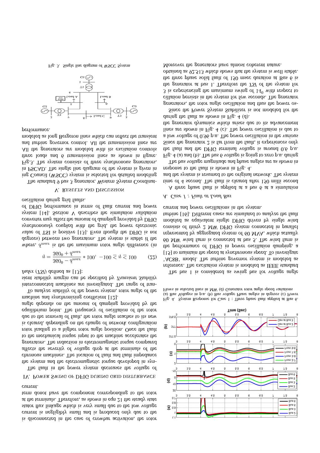
1 Impact of DFIG base Win Energy Conversion System on Fault Stuies an Power Swings Likin Simon Electrical Engineering Department Inian Institute of Technology, Maras K Shanti Swarup Electrical Engineering Department Inian Institute of Technology, Maras Abstract The integration of renewable energy sources into power systems changes the transient an fault current characteristics of the conventional gri. The variation in the system response uring gri isturbance like suen loa changes or fault woul cause the failure of traitional protection an control. Since the operating conition of DFIG epens on the characteristics of the gri an its control, the short circuit current in the system becomes more complex. This paper analyzes the short circuit characteristics of DFIG an evelops an analytical expression for the three phase fault current. Depening on the severity of the fault in terms of voltage rop, the fault current responses are evelope with an without crow bar resistance. The power swings that originates in the system when the fault is cleare are also analyze in the paper. The transient simulation stuies are performe in PSCAD/EMTDC by integrating DFIG to WSCC system. Case stuies are performe to analyze the impact of location of fault to the power swing an fault current contribution. Inex Terms Doubly fe inuction generator (DFIG), fault, power oscillation, reactive power, rotor angle oscillation, short circuit. I. INTRODUCTION The rise in electrical power eman an environmental concerns are riving the power gri towars greener an renewable energy integration. Among the renewable energy integration, win plants are growing fast in recent years [1]. With The DFIG base Win Energy Conversion System (WECS) is the most common in win power plants ue to its variable spee operation [2]. With the increase penetration of DFIG, the fault stuies becomes more complicate an power oscillations ue to any isturbance in the system nee to be analyze in etail. The capability of Low Voltage Rie Through (LVRT) [3] an four quarant operation which makes possible to operate at any esire power factor, makes DFIG base WECS ifferent from other renewable sources. The intermittent nature of win energy can also be mitigate upto an exten by proviing the battery storage in the DC link of DFIG [4]. DFIG base WECS consists of three parts as shown in Fig. 1: 1) Mechanical win riven turbine which can operate at variable win spees, 2) Doubly Fe Inuction Machine whose rotor terminals are externally available an 3) back to back voltage source converter (VSC) which ensures the biirectional power flows uring variable spees. The stator terminal of the machine is normally irectly connecte to the gri an the rotor terminals /14/$31. c 216 IEEE Fig. 1. Configuration of DFIG are connecte to the back to back converters. This converter is hitche back to the gri through a transformer to reuce the voltage rating of the converter. The back to back VSC converters are normally low rate (one thir rating of the machine). The integration of win energy makes the short circuit stuies more intrinsic. The 3 generator 9 bus, Western System Coorinating Council (WSCC) system is selecte for etaile moeling for transient stability stuies. The excitation control, governor control are moele for analyzing the rotor angle oscillation of the synchronous generators. Suen loa isturbance, in the extreme case of faults, will isturbs the rotor torque an correspons to rotor angle oscillation. These isturbance in the rotor angle will reflect as power oscillation in the entire system an in worst case, it can leas the system to collapse. The integration of low inertia renewable sources will make the system more weak [5]. The transient stability improvement with DFIG system is iscusse in [5]. The change in ynamics an operational characteristics of the conventional gri ue to the large penetration of DFIG is aresse. A ecouple FRT technique to enhance the system stability is iscusse in [6]. The optimal crowbar resistance is foun to improve the power transfer capability of the system. The etaile stuy on impact of the penetration of win integration shoul be one before implementing the control schemes. This paper iscusses the short circuit analysis an power angle oscillation with high penetration of win integration with power system.
2 II. TRANSIENT MODELING OF DFIG The basic circuit configuration of DFIG is as shown in Fig. 1. The stator terminal of woun rotor inuction machine is connecte irectly to the gri an rotor terminals through a step up transformer to reuce the voltage rating of the converters. During ifferent moe of operations like sub synchronous an super synchronous, the rotor circuit nees to supply power in both the irections. The back to back converters of IGBT switches with anti parallel ioes are employe as shown in Fig. 1 which allows the biirectional power flow. The DFIG is moele in synchronous reference frame (-q) to get the inepenent control of active an reactive powers [7]. The electromagnetic torque evelope in the machine can be expresse in terms of irect an quarature axis currents an flux as follows, T em = 3 2 P L m L s (ψ qs i r ψ s i qr ) (1) Where, P is the no of poles, L m an L s are mutual an self inuctances, ψ s an ψ qs are the axis an q axis stator flux, i r an i qr are the axis an q axis rotor currents. The synchronous rotating frame is selecte such that axis is aligne with the stator flux which results, ψ s = ψ an ψ qs = (2) Then the torque equation reuces to Similarly, Where, T em = 3 2 P L m L s ( ψ s i qr ) (3) ims = (1+σ s )i s +i r (4) ims : Magnetizing current σ s : Stator Leakage factor. σ s = Ls L m i s an i sq : axis an q axis stator currents Therefore the reactive power require to provie the magnetizing current can be fe either from stator sie or rotor sie. In this paper, all the magnetizing current is fe from rotor sie to maintain unity power factor at the DFIG terminals. The voltage balance equations at the gri sie converter terminals can be written as, v a i a v b = R i b +L i b + v bg (5) t v c i c i c v cg i a v ag Where, v a,v b,v c an v ag,v bg,v cg are the converter terminal an gri voltages respectively. The three phase active an reactive power can be expresse in q frame as, p = v i s +v q i qs (6) q = v q i s v i qs (7) For gri sie converter, axis is aligne with the stator voltage, v = V an v q = (8) Fig. 2. frame Vs I s R s σ sl σ rl L + jω rψ r Equivalent circuit of DFIG for transient stuies in stator reference The active an reactive power expression can be reuce to p = v i s an q = v i qs (9) Therefore, i s is proportional to active power flow an i qs is proportional to reactive power flow through the gri sie converter. The Rotor Sie Converter (RSC) is employe to control the electromagnetic torque evelope in the machine by regulating i qr as given in eqn 1 an thus to control the rotor spee. The part of magnetization current require by the machine can be supplie from the RSC by regulating i r as shown in eqn 4. The crowbar resistance is employe to limit the RSC current uring gri faults [8]. The crow bar is switche on once the stator voltage is ippe an provie a bypass for the rotor current thus preventing any amage to RSC ue to over current. The etaile analysis of fault current is iscusse in III. The main objective of Gri Sie Converter (GSC) to maintain the DC link voltage constant irrespective of power flow uring super synchronous an sub synchronous operation of DFIG. The GSC can also control the amount of reactive power injecte to the gri by regulating i qs as shown in eqn 9. Even if the RSC is isconnecte uring gri faults an crowbar bypasses the excess current from rotor, the GSC can maintain the DC link voltage constant [9]. This helps DFIG to stay connecte to the gri an resume its operation soon after the removal of fault. III. SHORT CIRCUIT CHARACTERISTICS OF DFIG The equivalent circuit of DFIG in stator reference frame is shown in Fig. 2. The stator an rotor equations can be written as V s = R s i s +(1+σ s )L t (i s)+l t i re jǫ (1) V r = R r i r +σ r L t i r +L t (i se jǫ ) The flux function equations corresponing to voltage balance eqn 1 can be expresse as. V s = R s i s + ψ s t V r = R r i r + ψ r t jω rψ r ψ s = σ s L i s +L o i r ψ r = σ r L i r +L o i s R r I r V r (11) (12)
3 Where, V s an V r : Stator an rotor voltage i s an i r : Stator an rotor currents R s an R r : Stator an rotor resistances L : Magnetizing inuctance σ s an σ r : Stator an rotor leakage factor ω ms : Synchronous spee ψ s an ψ r : Stator an rotor flux ǫ : Angle between stator an rotor axis ω r : Electrical angular velocity The rotor currents an the stator voltages are within the limits uring the normal operation of DFIG. Assume a fault occurs at a time of t at the gri which causes the stator voltage to rop to V s. It affects the flux linkages at stator an rotor. The analytical expression for the fault current without crowbar an with crowbar resistance are evelope in III-A an III-B respectively. A. Without crowbar resistance in RSC For the normal gri operations, the space vector of stator voltage is rotating at synchronous spee with constant amplitue. Assume a three phase fault occurs at the gri, the space vector voltage ecreases to a value of V s. Therefore, V s (t t ) = V s e jωs V s (t t ) = V se jωs The stator flux can be written as, (13) t ψ s + R s σ s L ψ s = V s R s σ s i r (14) As the current injecte from RSC to rotor is in slip frequency, the rotor flux will have the same spee as that of stator flux, ie, the rotor injecte current, slip frequency + rotor spee = stator flux frequency. There fore, the stator flux eqn 14 before an after fault can be written as, σ s L ψ s (t t ) = (V s I r R s )e jωst R s +jω s σ s L σ s L ψ s (t t ) = (V s I r R s )e jωst + (15) R s +jω s σ s L where, ψ e Rs σsl t ψ = σ sl (V s V s) R s +jω s σ s L e jωst Since the stator resistance is negligible compare to stator reactance, the eqn 15 can be reuce to, ψ s (t t ) = V s e ωst jω s ψ s (t t ) = V s e jωst + V s V s e jωst e Rs σsl t jω s jω s The stator current in terms of stator flux can written from eqn 12 as, i s = ψ s L i r (17) σ s L (16) Substituting the value of stator flux from eqn 16 in eqn 17, i s = V s V s e jωst e t/τs jω s σ s L {{ Transient DC Term V s + e jωst L i r jω s σ s L σ s L {{ Steay State Term (18) where, τ s : Stator time constant = σsl R s The DC transient term makes sure that the flux linkages are not change ue to abrupt ip in the stator voltage. The DC transient magnitue epens on the amount of voltage reuce ue to the fault an the stator time constant. The steay state term epens on the stator voltage magnitue an the amount of excitation current require by the machine. B. With Crowbar resistance The crowbar resistances are usually employe to limit the rotor current to safe margin uring the gri faults. Due to the limitation of RSC current, the rotor spee/electromagnetic torque cannot be controlle uring low voltage at the terminals. Since the DFIG terminals experiences a low voltage at its terminals, ue to the gri fault, it cannot eliver the electrical power to the gri, which will increase the rotor spee to a angerous value. The crowbar can be turne on uring the gri faults to issipate the energy from the mechanical turbine to a limit. Different types of crowbar connections are iscusse in [1], [11]. The analytical expression for the fault current provie from the stator is evelope in this section. Once the crowbar is turne on, the RSC is isconnecte from the rotor wining. Therefore, the rotor inuce current will be only ue to the stator flux. The stator flux equation in terms of stator voltage an stator parameters can written as, t ψ s + R s σ s L ψ s = V (19) As iscusse in III-A, the stator flux before an after fault can expresse as, ψ s (t t ) = V s e jωst jω s (2) ψ s (t t ) = V s e jωst + V s V s e jωst jω s jω s Therefore, eqn 2 an eqn 12 can use to fin the analytical expression for fault current contribution from DFIG. i s = V s V s e jωst e t/τs jω s σ s L {{ Transient DC Term + V s e jωst jω s σ s L {{ Steay State Term (21) By analyzing the fault currents of DFIG with an without crowbar resistances, the DC transient term is present ue to the constant flux linkage theorem. The transient term epens on the low voltage cause at the DFIG terminals ue to the gri fault. More the voltage ip in the terminal, more the severity of the fault current. But the transient term may ie out epening on the value of time constant of the stator. When the crowbar is not connecte in the rotor circuit, the term corresponing to the rotor current provie from the RSC will be present as shown in eqn 18. Since the RSC
4
5 (a) Stator Current in Amp RMS Satator Current in Amp (a) (c) From 2-7 From 3-9 From 7-5 From Fig. 5. DFIG Response for Case 1 : Three phase fault applie at. (a) a phase fault current supplie from DFIG Stator RMS Fault Current () Gen at Gen at The fault current contribution from DFIG is shown in Fig. 7. The terminal voltage of DFIG is ecrease to.6 p.u. causing the DC component in the stator. Once the fault is cleare, the terminal voltage is taking some time to reach back to 1p.u. The fault current is contribute from DFIG at this time. The DC component transient term ecay epens on the stator time constant of DFIG. Once the terminal voltage reaches at its nominal value of 1 p.u aroun 4.6 secon, the DFIG resumes its normal operation. B. Case 2 : Fault at Generator Bus A three phase sli fault is applie at bus 2 (generator bus) at a simulation time of 4 secon. The fault is cleare in 15 millisec resuming the prefault network. The bus voltage magnitue an phase angles are shown in Fig. 6 (a) an. Due to the avancement of generator rotor uring fault, the voltage phase angles are isturbe. This in turn causes the power oscillations in the entire system. The power flows through selecte lines are as shown in Fig. 6 (c). The generator rotor ynamics are shown in Fig. 6 (). The DFIG ynamics are shown in Fig. 7. The DFIG terminal voltage falls to.65 p.u. uring the fault an it is resume to its nominal value aroun 6.5 secons. Since the fault at bus 2 is nearer to DFIG terminals compare to Case 1, it is taking more time to reach the steay state after clearing the fault. The fault current from a phase reaches to a value of 17 A which is more than Case 1. Since the fault is at the Generator 2 terminals, it experiences more fluctuations compare to other generators. Therefore generator 2 an generator 3 becomes incoherent an they swing ifferently. The maximum swing between two machines is aroun 21 between generator 2 an generator 3. The TSI for the system for the fault at bus 2 is foun to be 88.9 which shows that the system is stable for the conition. C. Case 3 : Fault at the transmission line The three phase soli fault occurs at the mipoint of transmission line connecte between bus 5 an bus 7 at a simulation time of 4 secon. The fault is cleare by opening 37 Fig. 6. System Response for Case 2 : Three phase fault applie at. (a) Bus Voltages in p.u. Bus voltage Phase angles in egrees (c) Power Flows in selecte lines in MW () Generator rotor angle spee variations (a) Stator Current in Amp RMS Stator Current in AMP Fig. 7. DFIG Response for Case 2 : Three phase fault applie at. (a) a phase fault current supplie from DFIG Stator RMS Fault Current the circuit breakers at both the en of the faulte line after 15 milli secon. Therefore, the system configuration is change after clearing the fault. The system response to the line fault is shown in Fig. 8. The bus voltage magnitue an phase angles are shown in Fig. 8 (a) an. Since the system configuration is change after clearing the fault, the voltage phase angles are settle at a ifferent value from the prefault conition. The power flows in the line are also change an settles to a new operating points as shown in Fig. 8 (c). The power flowing through 7-8 an 4-5 are mostly affecte ue to the removal of the faulte line. The DFIG ynamics uring the fault are shown in Fig. 9. Since the fault is nearer to the DFIG compare to other cases, the fault current is maximum for Case 3. The DFIG terminal voltage settles own to the nominal value aroun 5.2 secons an the current reaches its steay state at the time. The stator
6 (a) (c) From From 3-9 From 7-5 From () Gen at Gen at Fig. 8. System Response for Case 3 : Three phase fault applie at line between 5 an 7. (a) Bus Voltages in p.u. Bus voltage Phase angles in egrees (c) Power Flows in selecte lines in MW () Generator rotor angle spee variations (a) Stator Current in Amp RMS Stator Current in Amp Fig. 9. DFIG Response for Case 3 : Three phase fault applie at the mipoint of the line 5-7. (a) a phase fault current supplie from DFIG Stator RMS Fault Current time constant epens the rate of ecay of the DC transient term of the fault current supplie from DFIG. The rms fault current supplie from on of the phases is aroun 258 A which is much larger than the other two cases. The TSI of the system for line fault at 5-7 is foun to be aroun 76. This shows the system is stable but not to the exten of other two cases. Once the fault is nearer to the DFIG terminals, which ecreases the terminal voltage to a low value, causes a very high fault current to flow from DFIG. VI. CONCLUSION The transient performance of DFIG connecte to a large system is iscusse in the paper. An analytical expression for the fault current contribute from DFIG with an without crowbar resistance is evelope. The fault current from DFIG consists of two terms viz, DC transient term which epens on the stator time constant (higher the value of resistance, higher the ecay rate) an steay state term which epens on the amount of voltage ippe at the DFIG terminal. The power oscillations in the system ue to the rotor ynamics after clearing the fault is stuie by applying fault at ifferent buses. It is shown from the simulation result that nearer the location of fault to the DFIG system, more the fault current contribution. The relays in the system must consier the DFIG ynamics an the transient fault current for its proper setting an coorination. This paper provies the stuy of the behavior of fault current contribution an power oscillations with the penetration of DFIG base win generators. REFERENCES [1] F. Blaabjerg, R. Teoorescu, M. Liserre, an A. V. Timbus, Overview of control an gri synchronization for istribute power generation systems, IEEE Transactions on Inustrial Electronics, vol. 53, no. 5, pp , Oct 26. [2] F. Blaabjerg an K. Ma, Future on power electronics for win turbine systems, IEEE Journal of Emerging an Selecte Topics in Power Electronics, vol. 1, no. 3, pp , Sept 213. [3] J. Morren an S. e Haan, Riethrough of win turbines with oublyfe inuction generator uring a voltage ip, Energy Conversion, IEEE Transactions on, vol. 2, no. 2, pp , June 25. [4] V. Ganti, B. Singh, S. Aggarwal, an T. Kanpal, Dfig-base win power conversion with gri power leveling for reuce gusts, Sustainable Energy, IEEE Transactions on, vol. 3, no. 1, pp. 12 2, Jan 212. [5] D. Gautam, V. Vittal, an T. Harbour, Impact of increase penetration of fig-base win turbine generators on transient an small signal stability of power systems, IEEE Transactions on Power Systems, vol. 24, no. 3, pp , Aug 29. [6] L. G. Meegahapola, T. Littler, an D. Flynn, Decouple-fig fault riethrough strategy for enhance stability performance uring gri faults, IEEE Transactions on Sustainable Energy, vol. 1, no. 3, pp , Oct 21. [7] S. Muller, M. Deicke, an R. De Doncker, Doubly fe inuction generator systems for win turbines, Inustry Applications Magazine, IEEE, vol. 8, no. 3, pp , May 22. [8] K. Ahsanullah an J. Ravishankar, Fault rie-through of oubly-fe inuction generators, in Power, Signals, Controls an Computation (EPSCICON), 212 International Conference on, Jan 212, pp [9] M. Rahimi an M. Parniani, Efficient control scheme of win turbines with oubly fe inuction generators for low-voltage rie-through capability enhancement, Renewable Power Generation, IET, vol. 4, no. 3, pp , May 21. [1] J. Vial, G. Aba, J. Arza, an S. Aurtenechea, Single-phase c crowbar topologies for low voltage rie through fulfillment of high-power oubly fe inuction generator-base win turbines, IEEE Transactions on Energy Conversion, vol. 28, no. 3, pp , Sept 213. [11] S. Hu, X. Lin, Y. Kang, an X. Zou, An improve low-voltage riethrough control strategy of oubly fe inuction generator uring gri faults, IEEE Transactions on Power Electronics, vol. 26, no. 12, pp , Dec 211. [12] R. Jalayer an B. T. Ooi, Frequency epenant estimation of amping an synchronizing torque coefficients in power systems, in 212 IEEE Power an Energy Society General Meeting, July 212, pp [13] L. Shi, S. Dai, Y. Ni, L. Yao, an M. Bazargan, Transient stability of power systems with high penetration of fig base win farms, in 29 IEEE Power Energy Society General Meeting, July 29, pp [14] L. G. Meegahapola, T. Littler, an D. Flynn, Decouple-fig fault riethrough strategy for enhance stability performance uring gri faults, IEEE Transactions on Sustainable Energy, vol. 1, no. 3, pp , Oct 21. [15] P. Kunur, Power System Stability an Control. McGraw Hill, [16] W. Qiao, R. Harley, an G. Venayagamoorthy, Effects of facts evices on a power system which inclues a large win farm, in Power Systems Conference an Exposition, 26. PSCE IEEE PES, Oct 26, pp
Dynamics of the synchronous machine
 ELEC0047 - Power system ynamics, control an stability Dynamics of the synchronous machine Thierry Van Cutsem t.vancutsem@ulg.ac.be www.montefiore.ulg.ac.be/~vct These slies follow those presente in course
Lecture 6: Control of Three-Phase Inverters
 Yoash Levron The Anrew an Erna Viterbi Faculty of Electrical Engineering, Technion Israel Institute of Technology, Haifa 323, Israel yoashl@ee.technion.ac.il Juri Belikov Department of Computer Systems,
Modeling and analysis of parallel connected permanent magnet synchronous generators in a small hydropower plant
 Proceeings of the 2006 IASME/WSEAS International Conference on Energy & Environmental Systems, Chalkia, Greece, May 8-10, 2006 (pp83-88) Moeling an analysis of parallel connecte permanent magnet synchronous
State Space Analysis of Power System Stability Enhancement with Used the STATCOM
 tate pace Analysis of Power ystem tability Enhancement with Use the ACOM M. Mahavian () - G. hahgholian () () Department of Electrical Engineering, Islamic Aza University, Naein Branch, Esfahan, Iran ()
Chapter 6. Electromagnetic Oscillations and Alternating Current
 hapter 6 Electromagnetic Oscillations an Alternating urrent hapter 6: Electromagnetic Oscillations an Alternating urrent (hapter 31, 3 in textbook) 6.1. Oscillations 6.. The Electrical Mechanical Analogy
Experimental Determination of Mechanical Parameters in Sensorless Vector-Controlled Induction Motor Drive
 Experimental Determination of Mechanical Parameters in Sensorless Vector-Controlle Inuction Motor Drive V. S. S. Pavan Kumar Hari, Avanish Tripathi 2 an G.Narayanan 3 Department of Electrical Engineering,
Determine Power Transfer Limits of An SMIB System through Linear System Analysis with Nonlinear Simulation Validation
 Determine Power Transfer Limits of An SMIB System through Linear System Analysis with Nonlinear Simulation Valiation Yin Li, Stuent Member, IEEE, Lingling Fan, Senior Member, IEEE Abstract This paper extens
ECE 422 Power System Operations & Planning 7 Transient Stability
 ECE 4 Power System Operations & Planning 7 Transient Stability Spring 5 Instructor: Kai Sun References Saaat s Chapter.5 ~. EPRI Tutorial s Chapter 7 Kunur s Chapter 3 Transient Stability The ability of
A Comparison between a Conventional Power System Stabilizer (PSS) and Novel PSS Based on Feedback Linearization Technique
 and Novel PSS Based on Feedback Linearization Technique") J. Basic. Appl. Sci. Res., ()9-99,, TextRoa Publication ISSN 9-434 Journal of Basic an Applie Scientific Research www.textroa.com A Comparison between a Conventional Power System Stabilizer (PSS) an Novel
J. Basic. Appl. Sci. Res., ()9-99,, TextRoa Publication ISSN 9-434 Journal of Basic an Applie Scientific Research www.textroa.com A Comparison between a Conventional Power System Stabilizer (PSS) an Novel
Modelling of Three Phase Short Circuit and Measuring Parameters of a Turbo Generator for Improved Performance
 Moelling of Three Phase Short Circuit an Measuring Parameters of a Turbo Generator for Improve Performance M. Olubiwe, S. O. E. Ogbogu, D. O. Dike, L. Uzoechi Dept of Electrical an Electronic Engineering,
ECE 692 Advanced Topics on Power System Stability 2 Power System Modeling
 ECE 692 Avance Topics on Power System Stability 2 Power System Moeling Spring 2016 Instructor: Kai Sun 1 Outline Moeling of synchronous generators for Stability Stuies Moeling of loas Moeling of frequency
Situation awareness of power system based on static voltage security region
 The 6th International Conference on Renewable Power Generation (RPG) 19 20 October 2017 Situation awareness of power system base on static voltage security region Fei Xiao, Zi-Qing Jiang, Qian Ai, Ran
Suppression Method of Rising DC Voltage for the Halt Sequence of an Inverter in the Motor Regeneration
 Suppression Metho of Rising DC Voltage for the Halt Sequence of an Inverter in the Motor Regeneration Jun-ichi Itoh Wataru Aoki Goh Teck Chiang Akio Toba Nagaoka University of Technology Fuji Electric
Deriving ARX Models for Synchronous Generators
 Deriving AR Moels for Synchronous Generators Yangkun u, Stuent Member, IEEE, Zhixin Miao, Senior Member, IEEE, Lingling Fan, Senior Member, IEEE Abstract Parameter ientification of a synchronous generator
Outcome of this lecture
 Outcome of this lecture At the en of this lecture you will be able to: List the ifferent parts of a synchronous machine Explain the operation principles of the machine Use the equivalent circuit moel of
Design A Robust Power System Stabilizer on SMIB Using Lyapunov Theory
 Design A Robust Power System Stabilizer on SMIB Using Lyapunov Theory Yin Li, Stuent Member, IEEE, Lingling Fan, Senior Member, IEEE Abstract This paper proposes a robust power system stabilizer (PSS)
Position Sensorless Control for an Interior Permanent Magnet Synchronous Motor SVM Drive with ANN Based Stator Flux Estimator
 International Journal of Computer an Electrical Engineering, Vol., No. 3, June, 1 Position Sensorless Control for an Interior Permanent Magnet Synchronous Motor SVM Drive with ANN Base Stator Flux Estimator
Investigation of local load effect on damping characteristics of synchronous generator using transfer-function block-diagram model
 ORIGINAL ARTICLE Investigation of local loa effect on amping characteristics of synchronous generator using transfer-function block-iagram moel Pichai Aree Abstract of synchronous generator using transfer-function
DYNAMIC PERFORMANCE OF RELUCTANCE SYNCHRONOUS MACHINES
 Annals of the University of Craiova, Electrical Engineering series, No 33, 9; ISSN 184-485 7 TH INTERNATIONAL CONFERENCE ON ELECTROMECHANICAL AN POWER SYSTEMS October 8-9, 9 - Iaşi, Romania YNAMIC PERFORMANCE
Electric Power Systems Research
 Electric Power Systems Research 84 (22 35 43 Contents lists available at SciVerse ScienceDirect Electric Power Systems Research jou rn al h om epage: www.elsevier.com/locate/epsr Observer-base nonlinear
State-Space Model for a Multi-Machine System
 State-Space Moel for a Multi-Machine System These notes parallel section.4 in the text. We are ealing with classically moele machines (IEEE Type.), constant impeance loas, an a network reuce to its internal
PES 1120 Spring 2014, Spendier Lecture 36/Page 1
 PES 0 Spring 04, Spenier ecture 36/Page Toay: chapter 3 - R circuits: Dampe Oscillation - Driven series R circuit - HW 9 ue Wenesay - FQs Wenesay ast time you stuie the circuit (no resistance) The total
Harmonic Modelling of Thyristor Bridges using a Simplified Time Domain Method
 1 Harmonic Moelling of Thyristor Briges using a Simplifie Time Domain Metho P. W. Lehn, Senior Member IEEE, an G. Ebner Abstract The paper presents time omain methos for harmonic analysis of a 6-pulse
Simulink model for examining dynamic interactions involving electro-mechanical oscillations in distribution systems
 University of Wollongong Research Online Faculty of Engineering an Information Sciences - Papers: Part A Faculty of Engineering an Information Sciences 205 Simulink moel for examining ynamic interactions
Doubly-Fed Induction Generator Wind Turbine Model for Fault Ride-Through Investigation
 32 ECTI TRANSACTIONS ON ELECTRICAL ENG., ELECTRONICS, AND COMMUNICATIONS VOL.11, NO.1 February 2013 Doubly-Fed Induction Generator Wind Turbine Model for Fault Ride-Through Investigation Yutana Chongjarearn
THE most important advantages of the variable speed wind
 Active an Reactive Power Control of a DFIG with MPPT for Variable Spee Win Energy Conversion using Sliing Moe Control Youcef Bekakra, Djilani Ben attous International Science Inex, Electrical an Computer
The Efficiency Optimization of Permanent Magnet Synchronous Machine DTC for Electric Vehicles Applications Based on Loss Model
 International Power, Electronics an Materials Engineering Conference (IPEMEC 015) The Efficiency Optimization of Permanent Magnet Synchronous Machine DTC for Electric Vehicles Applications Base on Loss
Simple Electromagnetic Motor Model for Torsional Analysis of Variable Speed Drives with an Induction Motor
 DOI: 10.24352/UB.OVGU-2017-110 TECHNISCHE MECHANIK, 37, 2-5, (2017), 347-357 submitte: June 15, 2017 Simple Electromagnetic Motor Moel for Torsional Analysis of Variable Spee Drives with an Inuction Motor
Dynamic Modeling and Analysis of Large-scale Power Systems in the DQ0 Reference Frame
 Dynamic Moeling an Analysis of Large-scale Power Systems in the DQ0 Reference Frame Juri Belikov Tallinn University of Technology juri.belikov@ttu.ee December 12, 2017 Juri Belikov (TUT) Moeling an Ientification
IPMSM Inductances Calculation Using FEA
 X International Symposium on Inustrial Electronics INDEL 24, Banja Luka, November 68, 24 IPMSM Inuctances Calculation Using FEA Dejan G. Jerkan, Marko A. Gecić an Darko P. Marčetić Department for Power,
The Energy Flow Approach for Oscillation Source Location and Damping Evaluation
 1 The Energy Flow Approach for Oscillation Source Location an Damping Evaluation Lei CHEN PhD, Associate Professor Department of Electrical Engineering Tsinghua University chenlei08@tsinghua.eu.cn Backgroun
Synchronous Machine Modeling
 ECE 53 Session ; Page / Fall 07 Synchronous Machine Moeling Reference θ Quarature Axis B C Direct Axis Q G F D A F G Q A D C B Transient Moel for a Synchronous Machine Generator Convention ECE 53 Session
Homework 7 Due 18 November at 6:00 pm
 Homework 7 Due 18 November at 6:00 pm 1. Maxwell s Equations Quasi-statics o a An air core, N turn, cylinrical solenoi of length an raius a, carries a current I Io cos t. a. Using Ampere s Law, etermine
Design and Application of Fault Current Limiter in Iran Power System Utility
 Australian Journal of Basic an Applie Sciences, 7(): 76-8, 13 ISSN 1991-8178 Design an Application of Fault Current Limiter in Iran Power System Utility M. Najafi, M. Hoseynpoor Department of Electrical
REAL TIME CONTROL OF DOUBLY FED INDUCTION GENERATOR. Benmeziane Meriem, Zebirate Soraya, Chaker Abelkader Laboratory SCAMRE, ENPO, Oran, Algeria
 REAL TIME CONTROL OF DOUBLY FED INDUCTION GENERATOR Benmeziane Meriem, Zebirate Soraya, Chaker Abelkader Laboratory SCAMRE, ENPO, Oran, Algeria This paper presents a real time simulation method of wind
Modeling and Control of a Marine Diesel Engine driving a Synchronous machine and a Propeller
 Moeling an Control of a Marine Diesel Engine riving a Synchronous machine an a Propeller Mutaz Tuffaha an Jan Tommy Gravahl Abstract In some esigns of power systems for marine vessels, large-size or meium-size
Modelling of Permanent Magnet Synchronous Motor Incorporating Core-loss
 Research Journal of Applie Sciences, Engineering an Technology 4(7): 846-85, ISSN: 4-7467 Maxwell Scientific Organization, Submitte: November, Accepte: December 9, Publishe: September, Moelling of Permanent
Predictive control of synchronous generator: a multiciterial optimization approach
 Preictive control of synchronous generator: a multiciterial optimization approach Marián Mrosko, Eva Miklovičová, Ján Murgaš Abstract The paper eals with the preictive control esign for nonlinear systems.
An inductance lookup table application for analysis of reluctance stepper motor model
 ARCHIVES OF ELECTRICAL ENGINEERING VOL. 60(), pp. 5- (0) DOI 0.478/ v07-0-000-y An inuctance lookup table application for analysis of reluctance stepper motor moel JAKUB BERNAT, JAKUB KOŁOTA, SŁAWOMIR
Vehicle Stability Improvement Based on Electronic Differential Using Sliding Mode Control
 7th WSEAS International Conference on Electric Power Systems, High Voltages, Electric Machines, Venice, Italy, November 1-3, 007 331 Vehicle Stability Improvement Base on Electronic Differential Using
Power Generation and Distribution via Distributed Coordination Control
 Power Generation an Distribution via Distribute Coorination Control Byeong-Yeon Kim, Kwang-Kyo Oh, an Hyo-Sung Ahn arxiv:407.4870v [math.oc] 8 Jul 204 Abstract This paper presents power coorination, power
A Voltage and Frequency Control Strategy for Stand-Alone Full Converter Wind Energy Conversion Systems
 energies Article A Voltage an Frequency Control Strategy for Stan-Alone Full Converter Win Energy Conversion Systems Anrés Peña Asensio * ID, Santiago Arnaltes Gómez ID, Jose Luis Roriguez-Ameneo, Manuel
AN INTRODUCTION TO AIRCRAFT WING FLUTTER Revision A
 AN INTRODUCTION TO AIRCRAFT WIN FLUTTER Revision A By Tom Irvine Email: tomirvine@aol.com January 8, 000 Introuction Certain aircraft wings have experience violent oscillations uring high spee flight.
Experimental Robustness Study of a Second-Order Sliding Mode Controller
 Experimental Robustness Stuy of a Secon-Orer Sliing Moe Controller Anré Blom, Bram e Jager Einhoven University of Technology Department of Mechanical Engineering P.O. Box 513, 5600 MB Einhoven, The Netherlans
Direct Computation of Generator Internal Dynamic States from Terminal Measurements
 Direct Computation of Generator nternal Dynamic States from Terminal Measurements aithianathan enkatasubramanian Rajesh G. Kavasseri School of Electrical En. an Computer Science Dept. of Electrical an
Chapter 31: RLC Circuits. PHY2049: Chapter 31 1
 Chapter 31: RLC Circuits PHY049: Chapter 31 1 LC Oscillations Conservation of energy Topics Dampe oscillations in RLC circuits Energy loss AC current RMS quantities Force oscillations Resistance, reactance,
Comparative Analysis of an integration of a Wind Energy Conversion System of PMSG and DFIG Models Connected to Power Grid
 International Journal of Electrical Engineering. ISSN 0974-2158 Volume 6, Number 3 (2013), pp. 231-248 International Research Publication House http://www.irphouse.com Comparative Analysis of an integration
Massachusetts Institute of Technology Department of Electrical Engineering and Computer Science Electric Machines
 Massachusetts Institute of Technology Department of Electrical Engineering and Computer Science 6.685 Electric Machines Problem Set 10 Issued November 11, 2013 Due November 20, 2013 Problem 1: Permanent
ensembles When working with density operators, we can use this connection to define a generalized Bloch vector: v x Tr x, v y Tr y
 Ph195a lecture notes, 1/3/01 Density operators for spin- 1 ensembles So far in our iscussion of spin- 1 systems, we have restricte our attention to the case of pure states an Hamiltonian evolution. Toay
6. Friction and viscosity in gasses
 IR2 6. Friction an viscosity in gasses 6.1 Introuction Similar to fluis, also for laminar flowing gases Newtons s friction law hols true (see experiment IR1). Using Newton s law the viscosity of air uner
Unbalanced-Grid-Fault Ride-Through Control for a Doubly Fed. Induction Generator Wind Turbine with Series Grid-Side Converter
 Unbalanced-Grid-Fault Ride-Through Control for a Doubly Fed Induction Generator Wind Turbine with Series Grid-Side Converter YONG LIAO, HUI LI *, JUN YAO State Key Laboratory of Power Transmission Equipment
Systematic Design of Virtual Component Method for Inverter-Based Microgrids
 Systematic Design of Virtual Component Metho for Inverter-Base Microgris Po-Hsu Huang 1, Petr Vorobev 1, Mohame Al Hosani 3, James L. Kirtley 1, an Konstantin Turitsyn 1 1 Massachusetts Institute of Technology
Research Article Development of Digital Control for High Power Permanent-Magnet Synchronous Motor Drives
 Mathematical Problems in Engineering Volume 214, Article ID 926727, 1 pages http://x.oi.org/1.1155/214/926727 Research Article Development of Digital Control for High Power Permanent-Magnet Synchronous
Control of Wind Turbine Generators. James Cale Guest Lecturer EE 566, Fall Semester 2014 Colorado State University
 Control of Wind Turbine Generators James Cale Guest Lecturer EE 566, Fall Semester 2014 Colorado State University Review from Day 1 Review Last time, we started with basic concepts from physics such as
EE 370L Controls Laboratory. Laboratory Exercise #7 Root Locus. Department of Electrical and Computer Engineering University of Nevada, at Las Vegas
 EE 370L Controls Laboratory Laboratory Exercise #7 Root Locus Department of Electrical an Computer Engineering University of Nevaa, at Las Vegas 1. Learning Objectives To emonstrate the concept of error
Open Access An Exponential Reaching Law Sliding Mode Observer for PMSM in Rotating Frame
 Sen Orers for Reprints to reprints@benthamscience.ae The Open Automation an Control Systems Journal, 25, 7, 599-66 599 Open Access An Exponential Reaching Law Sliing Moe Observer for PMSM in Rotating Frame
MEASUREMENT OF LOSSES IN DIRECT TORQUE CONTROLLED PERMANENT MAGNET SYNCHRONOUS MOTOR BY ANALYSIS AND EXPERIMENTAL SETUP
 IJRET: International Journal of Research in Engineering an Technology eissn: 2319-1163 pissn: 2321-738 MEASUREMENT OF LOSSES IN DIRECT TORQUE CONTROLLED PERMANENT MAGNET SYNCHRONOUS MOTOR BY ANALYSIS AND
Systematic Design of Virtual Component Method for Inverter-Based Microgrids
 Systematic Design of Virtual Component Metho for Inverter-Base Microgris Po-Hsu Huang 1, Petr Vorobev 1, Mohame Al Hosani, James L. Kirtley 1, an Konstantin Turitsyn 1 1 Massachusetts Institute of Technology
Tutorial Test 5 2D welding robot
 Tutorial Test 5 D weling robot Phys 70: Planar rigi boy ynamics The problem statement is appene at the en of the reference solution. June 19, 015 Begin: 10:00 am En: 11:30 am Duration: 90 min Solution.
Physics 115C Homework 4
 Physics 115C Homework 4 Problem 1 a In the Heisenberg picture, the ynamical equation is the Heisenberg equation of motion: for any operator Q H, we have Q H = 1 t i [Q H,H]+ Q H t where the partial erivative
WITH the recent widescale deployment of Phasor Measurement. Using Effective Generator Impedance for Forced Oscillation Source Location
 1 Using Effective Generator Impeance for Force Oscillation Source Location Samuel Chevalier, Stuent Member, IEEE, Petr Vorobev, Member, IEEE, Konstantin Turitsyn, Member, IEEE arxiv:178.1893v cs.sy 4 May
Circuit-Based Induction Motor Drive Reliability under Different Control Schemes and Safe-Mode Operation
 Circuit-Base nuction Motor Drive Reliability uner Different Control Schemes an Safe-Moe Operation Ali M. Bazzi, Xiangyu Ding, Alejanro Dominguez-García, an Philip T. Krein Grainger Center for Electric
Steady State Modeling of Doubly Fed Induction Generator
 Steady State Modeling of Douly Fed Induction Generator Bhola Jha 1, Dr. K. R. M Rao 2 1 Dept. of Electrical Engg., G. B. Pant Engg. College, Pauri-Garhwal, India 2 Dept. of Electrical Engg., M. J. College
Progress In Electromagnetics Research B, Vol. 34, , 2011
 Progress In Electromagnetics Research B, Vol. 34, 225 245, 211 INFLUENCE OF CONSTANT VALUES AND MOTOR PARAMETERS DEVIATIONS ON THE PERFORMANCE OF THE ADAPTIVE SLIDING-MODE OBSERVER IN A SENSORLESS INDUCTION
Power System Stability and Control. Dr. B. Kalyan Kumar, Department of Electrical Engineering, Indian Institute of Technology Madras, Chennai, India
 Power System Stability and Control Dr. B. Kalyan Kumar, Department of Electrical Engineering, Indian Institute of Technology Madras, Chennai, India Contents Chapter 1 Introduction to Power System Stability
DIRECT TORQUE AND FLUX CONTROL OF ASYMMETRICAL SIX-PHASE INDUCTION MOTOR WITH ZERO SEQUENCE COMPONENTS ELIMINATION
 Rev. Roum. Sci. Techn. Électrotechn. et Énerg. Vol. 6,, pp. 36, Bucarest, 7 DIRECT TORQUE AND FLUX CONTROL OF ASYMMETRICAL SIX-PHASE INDUCTION MOTOR WITH ZERO SEQUENCE COMPONENTS ELIMINATION NAVID REZA
Behaviour of synchronous machine during a short-circuit (a simple example of electromagnetic transients)
") ELEC0047 - Power system dynamics, control and stability (a simple example of electromagnetic transients) Thierry Van Cutsem t.vancutsem@ulg.ac.be www.montefiore.ulg.ac.be/~vct October 2018 1 / 25 Objectives
ELEC0047 - Power system dynamics, control and stability (a simple example of electromagnetic transients) Thierry Van Cutsem t.vancutsem@ulg.ac.be www.montefiore.ulg.ac.be/~vct October 2018 1 / 25 Objectives
Transmission Line Matrix (TLM) network analogues of reversible trapping processes Part B: scaling and consistency
 network analogues of reversible trapping processes Part B: scaling and consistency") Transmission Line Matrix (TLM network analogues of reversible trapping processes Part B: scaling an consistency Donar e Cogan * ANC Eucation, 308-310.A. De Mel Mawatha, Colombo 3, Sri Lanka * onarecogan@gmail.com
Transmission Line Matrix (TLM network analogues of reversible trapping processes Part B: scaling an consistency Donar e Cogan * ANC Eucation, 308-310.A. De Mel Mawatha, Colombo 3, Sri Lanka * onarecogan@gmail.com
A Simple Model for the Calculation of Plasma Impedance in Atmospheric Radio Frequency Discharges
 Plasma Science an Technology, Vol.16, No.1, Oct. 214 A Simple Moel for the Calculation of Plasma Impeance in Atmospheric Raio Frequency Discharges GE Lei ( ) an ZHANG Yuantao ( ) Shanong Provincial Key
Time-of-Arrival Estimation in Non-Line-Of-Sight Environments
 2 Conference on Information Sciences an Systems, The Johns Hopkins University, March 2, 2 Time-of-Arrival Estimation in Non-Line-Of-Sight Environments Sinan Gezici, Hisashi Kobayashi an H. Vincent Poor
IN many important applications for power electronics such
 IEEE TRANSACTIONS ON POWER ELECTRONICS, VOL. 30, NO. 3, MARCH 2015 1591 Power Controllability of a Three-Phase Converter With an Unbalance AC Source Ke Ma, Member, IEEE, Wenjie Chen, Stuent Member, IEEE,
Incorporation of Asynchronous Generators as PQ Model in Load Flow Analysis for Power Systems with Wind Generation
 Incorporation of Asynchronous Generators as PQ Model in Load Flow Analysis for Power Systems with Wind Generation James Ranjith Kumar. R, Member, IEEE, Amit Jain, Member, IEEE, Power Systems Division,
THE SPEED CONTROL OF PERMANENT MAGNET SYNCHRONOUS MOTOR USING FUZZY LOGIC AND SELF TUNING FUZZY PI CONTROLLER
 THE SPEED CONTROL OF PERMANENT MAGNET SYNCHRONOUS MOTOR USING FUZZY LOGIC AND SELF TUNING FUZZY PI CONTROLLER Abulhakim KARAKAYA Ercüment KARAKAŞ e-mail: akarakaya@kou.eu.tr e-mail: karakas@kou.eu.tr Department
Electromagnetic Torque From Event Report Data A Measure of Machine Performance
 Electromagnetic Torque From Event Report Data A Measure of Machine Performance Derrick Haas and Dale Finney Schweitzer Engineering Laboratories, Inc. 7 SEL Overview Electromagnetic torque calculation Modeling
Vector Control Strategies to Enable Equal Frequency Operation of the Modular Multilevel Matrix Converter
 Vector Control Strategies to Enable Equal Frequency Operation of the Moular Multilevel Matrix Converter M. Diaz 1, M. Espinosa, F. Rojas 1, P. Wheeler, R. Carenas 4 1 University of Santiago of Chile, Chile,
The Modeling and Analysis of Grid Connected DFIG with Low-Voltage Ride- Through Solution Using Series Compensator
 The Modeling and Analysis of Grid Connected DFIG with Low-Voltage Ride- Through Solution Using Series Compensator Khasim Shaik 1, S.Srinu 2, Jan Bhasha Shaik 3 1 Post Graduate Student (M.Tech), Newton
ECE 585 Power System Stability
 Homework 1, Due on January 29 ECE 585 Power System Stability Consider the power system below. The network frequency is 60 Hz. At the pre-fault steady state (a) the power generated by the machine is 400
Transient Analysis of Doubly Fed Wind Power Induction Generator Using Coupled Field-Circuit Model
 Publication P2 Seman, S., Kanerva, S., Niiranen, J., Arkkio, A. 24. Transient Analysis of Wind Power Doubly Fed Induction Generator Using Coupled Field Circuit Model, Proceedings of ICEM 24, 5-8 September
A Simplified State Model for Wind Turbines
 A Simplified State Model for Wind Turbines Nuno M. L. Bernardo Student nº55250 of Instituto Superior Técnico Technical University of Lisbon Lisbon, Portugal Abstract This thesis presents studies relatively
AN3400 Application note
 Application note Analysis an simulation of a BJT complementary pair in a self-oscillating CFL solution ntrouction The steay-state oscillation of a novel zero-voltages switching (ZS) clampe-voltage (C)
Chapter 14: Vibration Generations Mechanisms: Self Excited Vibration
 hapter 14: ibration Generations echanisms: Self Ecite ibration Introuction: Self-ecite systems begin to vibrate of their own accor spontaneously, the amplitue increasing until some nonlinear effect limits
6.003 Homework #7 Solutions
 6.003 Homework #7 Solutions Problems. Secon-orer systems The impulse response of a secon-orer CT system has the form h(t) = e σt cos(ω t + φ)u(t) where the parameters σ, ω, an φ are relate to the parameters
Electronic Devices and Circuit Theory
 Instructor s Resource Manual to accompany Electronic Devices an Circuit Theory Tenth Eition Robert L. Boylesta Louis Nashelsky Upper Sale River, New Jersey Columbus, Ohio Copyright 2009 by Pearson Eucation,
QUESTION BANK ENGINEERS ACADEMY. Power Systems Power System Stability 1
 ower ystems ower ystem tability QUETION BANK. A cylindrical rotor generator delivers 0.5 pu power in the steady-state to an infinite bus through a transmission line of reactance 0.5 pu. The generator no-load
CURRENT ELECTRICITY Q.1
 CUENT EECTCTY Q. Define Electric current an its unit.. Electric Current t can be efine as the time rate of flow of charge in a conuctor is calle Electric Current. The amount of flow of charge Q per unit
Experimental determination of mechanical parameters in sensorless vector-controlled induction motor drive
 Sāhanā Vol. 42, No. 8, August 207, pp. 285 297 DOI 0.007/s2046-07-0664-2 Ó Inian Acaemy of Sciences Experimental etermination of mechanical parameters in sensorless vector-controlle inuction motor rive
Non-Superconducting Fault Current Limiter
 Proceeings o the 5th WEA International Conerence on Applications o Electrical Engineering, Prague, Czech Republic, March -, 6 (pp-7) Non-uperconucting Fault Current Limiter A. CHARMIN*, M. TARAFDAR HAQUE,
Laplacian Cooperative Attitude Control of Multiple Rigid Bodies
 Laplacian Cooperative Attitue Control of Multiple Rigi Boies Dimos V. Dimarogonas, Panagiotis Tsiotras an Kostas J. Kyriakopoulos Abstract Motivate by the fact that linear controllers can stabilize the
Electric Motor Performance Improvement Using Auxiliary Windings and Capacitance Injection
 Electric Motor Performance Improvement Using Auxiliary Winings an Capacitance Injection 2 Nicolae DV Tshwane University of Technology South Africa 1 Introuction Generally, some electric machines such as
Module 2. DC Circuit. Version 2 EE IIT, Kharagpur
 Moule 2 DC Circuit Lesson 9 Analysis of c resistive network in presence of one non-linear element Objectives To unerstan the volt (V ) ampere ( A ) characteristics of linear an nonlinear elements. Concept
Characteristic Study for Integration of Fixed and Variable Speed Wind Turbines into Transmission Grid
 Characteristic Study for Integration of Fixed and Variable Speed Wind Turbines into Transmission Grid Shuhui Li 1, Tim Haskew 1, R. Challoo 1 Department of Electrical and Computer Engineering The University
Analysis and Design of PSS Based on Sliding Mode Control Theory for SMIB
 Analysis an Design of P Base on liing Moe Control Theory for MIB Amin Rajabi, Ghazanfar hahgholian, Bahram Karimi, Mohamma Reza Yosefi Department of Electrical Engineering Islamic Aza University Najafaba
Dynamics of a Microgrid Supplied by Solid Oxide Fuel Cells 1
 Bulk Power System Dynamics an Control - VII, August 19-4, 007, Charleston, South Carolina, USA 1 Dynamics of a Microgri Supplie by Soli Oxie Fuel Cells 1 Eric M. Fleming Ian A. Hiskens Department of Electrical
Arm Voltage Estimation Method for Compensated Modulation of Modular Multilevel Converters
 Arm Voltage Estimation Metho for Compensate Moulation of Moular Multilevel Converters Ael A. Taffese Elisaetta Teeschi Dept. of Electric Power Engineering Norwegian University of Science an Technology
Fault ride through study of doubly fed induction generator wind turbine in real-time simulation environment
 Fault ride through study of doubly fed induction generator wind turbine in real-time simulation environment A.S. Mäkinen, P. auttamus, O. Raipala, S. Repo, H.Tuusa TAMPERE UNIVERSITY OF TECHNOOGY Korkeakoulunkatu
arxiv: v1 [math.ca] 9 Jan 2016
![arxiv: v1 [math.ca] 9 Jan 2016](/thumbs/84/91048047.jpg "arxiv: v1 [math.ca] 9 Jan 2016") Local Weak Observability Conitions of Sensorless AC Drives Mohama Koteich, Stuent Member, IEEE, Abelmalek Maloum, Gilles Duc an Guillaume Sanou arxiv:1601.06129v1 [math.ca] 9 Jan 2016 KEYWORDS Sensorless
Local Weak Observability Conitions of Sensorless AC Drives Mohama Koteich, Stuent Member, IEEE, Abelmalek Maloum, Gilles Duc an Guillaume Sanou arxiv:1601.06129v1 [math.ca] 9 Jan 2016 KEYWORDS Sensorless
CONTROL AND PERFORMANCE OF A NINE PHASE SYNCHRONOUS RELUCTANCE DRIVE
 CONTRO AN PERFORMANCE OF A NINE PHASE SYNCHRONOUS REUCTANCE RIVE Abstract C.E. Coates*,. Platt** an V.J. Gosbell ** * epartment of Electrical an Computer Engineering Uniersity of Newcastle ** epartment
Thermal conductivity of graded composites: Numerical simulations and an effective medium approximation
 JOURNAL OF MATERIALS SCIENCE 34 (999)5497 5503 Thermal conuctivity of grae composites: Numerical simulations an an effective meium approximation P. M. HUI Department of Physics, The Chinese University
1. The electron volt is a measure of (A) charge (B) energy (C) impulse (D) momentum (E) velocity
 charge (B) energy (C) impulse (D) momentum (E) velocity") AP Physics Multiple Choice Practice Electrostatics 1. The electron volt is a measure of (A) charge (B) energy (C) impulse (D) momentum (E) velocity. A soli conucting sphere is given a positive charge Q.
AP Physics Multiple Choice Practice Electrostatics 1. The electron volt is a measure of (A) charge (B) energy (C) impulse (D) momentum (E) velocity. A soli conucting sphere is given a positive charge Q.
Eigenvalue Analysis of Subsynchronous Resonance Study in Series Compensated Wind Farm
 e-issn: 2349-9745 p-issn: 2393-8161 Scientific Journal Impact Factor (SJIF): 1.711 International Journal of Modern Trends in Engineering and Research www.ijmter.com Eigenvalue Analysis of Subsynchronous