Chapter 6. Electromagnetic Oscillations and Alternating Current
|
|
|
- Nathan O’Connor’
- 5 years ago
- Views:
Transcription
1 hapter 6 Electromagnetic Oscillations an Alternating urrent
2 hapter 6: Electromagnetic Oscillations an Alternating urrent (hapter 31, 3 in textbook) 6.1. Oscillations 6.. The Electrical Mechanical Analogy 6.3. Dampe Oscillations in an ircuit 6.4. Alternating urrent 6.5. Three Simple ircuits 6.6. The Series ircuit 6.7. Power in Alternating urrent ircuits 6.8. Transformers
3 Overview n the previous chapters, we have stuie the basic physics of electric an magnetic fiels an how energy can be store in capacitors an inuctors. n this chapter, we will stuy the associate applie physics, in which the energy store in one location can be transferre to another location so that can be put to use, e.g., energy prouce at a power plant can be transferre to your home to run a computer. The moern civilization woul be impossible without this applie physics.
.")
4 Boiler Turbine Generator Electricity cables Fuel Furnace ooling tower Step-up transformer Step-own transformer Pylons Appliances Homes n most parts of the worl, electrical energy is transferre not as a irect current but as a sinusoially oscillating current (alternating current, or ac). The challenge to us is to esign ac systems that transfer energy efficiently an to buil appliances that make use of that energy.
5 6.1. Oscillations: Oscillations, Qualitatively: n an circuits the charge, current, an potential ifference grow an ecay exponentially. On the contrary, in an circuit, the charge, current, an potential ifference vary sinusoially with perio T an angular frequency. The resulting oscillations of the capacitor s electric fiel an the inuctor s magnetic fiel are sai to be electromagnetic oscillations.
6 8 stages in a single cycle of oscillation of a resistance less circuit
7 The energy store in the electric fiel of the capacitor at any time is q U E where q is the charge on the capacitor at that time. The energy store in the magnetic fiel of the inuctor at any time is U B i where i is the current through the inuctor at that time. As the circuit oscillates, energy shifts back an forth from one type of store energy to the other, but the total amount is conserve.


8 The time-varying potential ifference (or voltage) v that exists across the capacitor is: v 1 q To measure i, we can connect a small resistance in series with the capacitor an inuctor then measure the time-varying potential ifference v across it: v i n actual circuits, the oscillations o not continue forever because some resistance will issipate electrical an magnetic energy as thermal energy

9 6.. The Electrical Mechanical Analogy: One can make an analogy between the oscillating system an an oscillating block spring system. Here we have the following analogies: Thus, The angular frequency: k m (block spring system) 1 ( circuit)
10 The Block-Spring Oscillator: 1 1 U U U mv kx b s U 1 1 v x mv kx mv kx 0 t t t t x m kx 0 x X cos( t ) (isplacement) t The Oscillator: U U t U t q B U E i t 1 q i q q i i t 0 ( oscillations) i Prove the angular frequency of q q t : phase constant q t 0 ; k m q Qcos( t ) (charge) Q sin( t ) (current)
11 The amplitue : Q i sin( t ) Angular Frequencies: The equation to calculate charge q is inee the solution of the oscillations equation with 1/, we can test: q Qcos( t ) We have t t q 1 q 0 ( oscillations) Qcos( t ) 1 1 Qcos( t ) 0
 ( t ) Note that: The maximum values of U E an U B are both Q /. At any instant the sum of U E an U B is equal to Q /, a constant. When U E is maximum, U B is zero, an conversely.")
12 Electrical an Magnetic Energy Oscillations: The electrical energy store in the circuit at time t is, q Q U cos E ( t ) The magnetic energy is: 1 1 U i Q sin B But Therefore: 1 U B ( circuit) Q sin ( t ) ( t ) Note that: The maximum values of U E an U B are both Q /. At any instant the sum of U E an U B is equal to Q /, a constant. When U E is maximum, U B is zero, an conversely.
 is not constant; instea, it")

13 6.3. Dampe Oscillations in an ircuit: A circuit containing resistance, inuctance, an capacitance is calle an circuit With, the total energy U of the circuit (the sum of U E an U B ) is not constant; instea, it ecreases with time as energy is transferre to thermal energy in the resistance. The oscillations of charge, current, an potential ifference continuously ecrease in amplitue, an the oscillations are sai to be ampe.
14 Analysis: U U B U The total energy ecreases as U transferre to thermal energy substituting q/t for i an q/t for i/t, we have: E i U i q q i i t t t t q q Qe q 1 q 0 ( circuit) t t / q cos( ' t ) Where ' ( / ) An 1/ U E q Qe t / cos( ' t ) Q e t / cos ( ' t )
 is calle the riving angular frequency, an is the amplitue of the riven")
15 6.4. Alternating urrent (A): The oscillations in an circuit will not amp out if an external emf evice supplies enough energy to make up for the energy issipate as thermal energy The basic mechanism of an A generator is a conucting loop rotate in an external magnetic fiel The inuce emf: m sin t i sin( t ) is calle the riving angular frequency, an is the amplitue of the riven current.
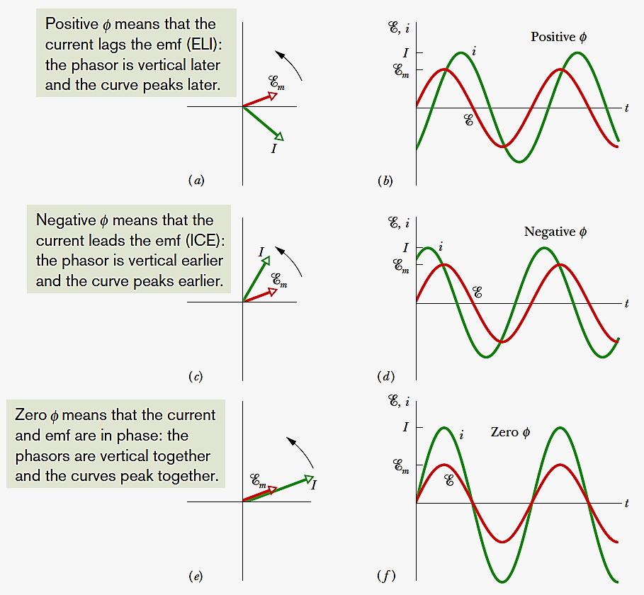
16 Force Oscillations: Unampe circuits an ampe circuits oscillate at: 1/ that is natural angular frequency When the circuit is connecte to an external alternating emf, charge, potential ifference an current oscillate with riving angular frequency, these oscillations are the so-calle riven oscillations or force oscillations The amplitue of the current in the circuit is maximum when =, a conition known as resonance A generator, represente by a sine wave in a circle, prouces an alternating emf that establishes an alternating current; the irections of the emf an currents are inicate here at only instant.
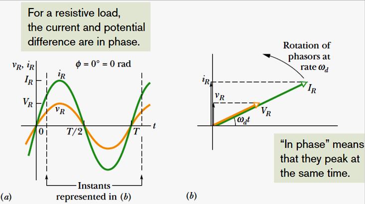
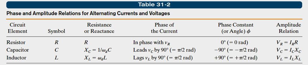
17 6.5. Three Simple ircuits: A esistive oa: v 0 v i m v sin t sin t sin t Note: for a purely resistive loa the phase constant = 0. v (t) an i (t) are in phase ( = 0 o ), which means their corresponing maxima (an minima) occur at the same times. The time-varying quantities v an i can also be represente geometrically by phasors (vectors that rotate aroun an origin) with the following properties: angular spee (rotate counterclockwise with ). length (representing the amplitue of an ) projection (representing v an i on the vertical axis); rotation angle (to be equal to the phase t at time t)
18
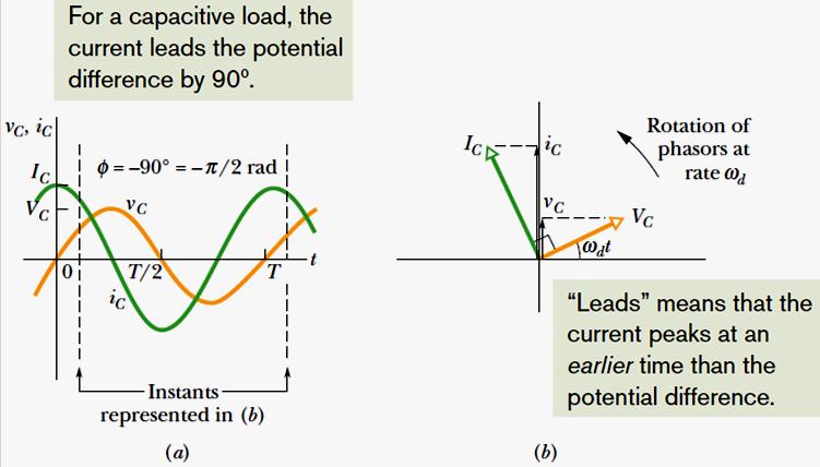
19 6.5.. A apacitive oa: v q i v q t X sin t sin t cos 1 X is calle the capacitive reactance of a capacitor. The S unit of X is the ohm (), just as for resistance. cos t sin( t 90 i sin( t 0 t (capacitive ) ), i 0-90 X reactance) sin( t 90 0 ) X (capacitor)
20
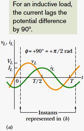
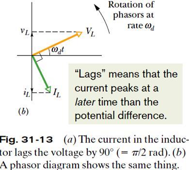
21 An nuctive oa: Potential ifference across the inuctance: From: i i i t (1) an () ntegrating: X i sin( t i t v v sin t X, the inuctive reactance, epens on the riving angular frequency. The unit of the inuctive time constant (=/) inicates that the S unit of X is the ohm. i t sin tt sin cos t X (inuctivereactance) 90 0 ); i () (1) t sin( t ) X (inuctor)
22
23


24 6.6. The Series ircuit: () The emf phasor is equal to the vector sum of the three voltage phasors of (b).here, voltage phasors an have been ae vectorially to yiel their net phasor ( - ).
 ) 1/ ( m X X tan (phaseconstant) tan X")
25 m t sin sin( ) t i m X X ( ) m X X (impeance efine) ) ( X X Z (current amp litue) ) 1/ ( m X X tan (phaseconstant) tan X X
26
27 esonance: ( m 1/ ) (current amp litue) For a given resistance, that amplitue is a maximum when the quantity ( -1/ ) in the enominator is zero. 1 1 (maximum ) The maximum value of occurs when the riving angular frequency matches the natural angular frequency that is, at resonance. 1 (resonance)

28 esonance curves for a riven circuit with 3 values of. The horizontal arrow on each curve measures the curve s half-with, which is the with at the half-maximum level an is a measure of the sharpness of the resonance. X >X X <X
29 The Parallel ircuit: m t sin - t i m sin ( ) X X Z Z tan 1 1 tan
: P avg rms P avg rms oot-mean-square: rm s P P avg avg rm s Z rms Z rms rms rms rms rm s an ( X X ) cos rms rms rms Z m Where: cos m Z")
30 6.7. Power in A ircuits: The instantaneous rate at which energy is issipate in the resistor: P i sin( t ) sin ( t ) The average rate (average power): P avg rms P avg rms oot-mean-square: rm s P P avg avg rm s Z rms Z rms rms rms rms rm s an ( X X ) cos rms rms rms Z m Where: cos m Z Z
31 6.8. Transformers: n electrical power istribution systems, for reasons of safety an efficient equipment esign to eal with relatively low voltages at both the generating en (the electrical power plant) an the receiving en (the home or factory). For ex: Noboy wants an electric toaster or a chil s electric train to operate at 10 k. On the other han, in the transmission of electrical energy from the generating plant to the consumer, we want the lowest practical current (hence the largest practical voltage) to minimize losses (often calle ohmic losses) in the transmission line.
32 Example: onsier a 500 k line use to transmit electrical energy from Hòa Bình to HM city, 1500 km away. Suppose that the current is 500 A an the power factor is close to unity. So, energy is supplie at the average rate: P avg = = = (500 x 10 3 )(500A) = 50 MW The resistance of the transmission line: r = 0. /km So, = 0. /km x 1500 km = 330 Energy is issipate ue to at a rate: P avg = = 500 x 330 = 8.5 MW, about 33% f we increase the current to 65 A an reuce the voltage to 400 K, giving the same average rate of 50 MW: P avg = = 75 x 330 = 18.9 MW, about 5% Hence the general energy transmission rule: Transmit at the highest possible voltage an the lowest possible current.

33 Transformer: A evice can raise an lower the ac voltage in a circuit, keeping the prouct current voltage essentially constant. The ieal transformer consists of two coils, with ifferent numbers of turns, woun aroun an iron core. n the primary coil with N p : m sint The seconary coil with N s turns. The primary current magnetizing (very small) lags the primary voltage P by 90 0, so no power is elivere from the generator to the transformer (cos = 0). The small sinusoially changing primary current prouces a sinusoially changing magnetic flux B in the iron core, proucing an emf (B/t) in each turn of the seconary. This emf turn is the same in the primary an the seconary. Across the primary: p = turn N p ; Similarly, across n : s = turn N s. S P N N S P (transformation of f N s >N p, the evice is a step-up transformer: s > p. f N s <N p, it is a step-own transformer. A basic transformer circuit voltage)
34 So far, switch S is open, so no energy is transferre from the generator to the rest of the circuit. f we now close S to connect the seconary to the resistive loa : 1. An alternating current S appears, with energy issipation rate S = S /. S inuces an opposing emf in the primary winings 3. P of the primary cannot change in response to this opposing emf because it must always be equal to the emf provie by the generator 4. To maintain P, the generator prouces (in aition to mag ) an alternating current P in the primary circuit. The magnitue an phase constant of P are just those require for the emf inuce by P in the primary to exactly cancel the emf inuce there by S. Because the phase constant of P is not 90 0, so P can transfer energy (P avg = rms rms cos) to the primary.
35 Here eq is the value of the loa resistance as seen by the generator: S S P P f no energy is lost along the way, conservation of energy requires that P P S S P S P S P P S S N N N N N N 1 1 currents) (transformation of S P P S N N eq P P (equivalent resistance) N N S P eq


 saturates the iron core, this")
36 Solar Activity an Power-Gri Systems: A solar flare: A huge loop of e- an p extens outwar from the Sun s surface The particles prouce a current, calle an electrojet, setting up a B fiel The transmission line, the groun, an the wires grouning the transformers form a conucting loop. An electrojet varies in both size an location, proucing an emf an a current. The current G (G: Geomagnetically nuce urrent) saturates the iron core, this isrupts the power transmission. Source: National Geographic

37
38
39 Homework: 1,, 7, 9, 10, 17, 3, 5, 9, 3, 38, 41, 48, 53 (pages )
PES 1120 Spring 2014, Spendier Lecture 36/Page 1
 PES 0 Spring 04, Spenier ecture 36/Page Toay: chapter 3 - R circuits: Dampe Oscillation - Driven series R circuit - HW 9 ue Wenesay - FQs Wenesay ast time you stuie the circuit (no resistance) The total
Electromagnetic Oscillations and Alternating Current. 1. Electromagnetic oscillations and LC circuit 2. Alternating Current 3.
 Electromagnetic Oscillations and Alternating Current 1. Electromagnetic oscillations and LC circuit 2. Alternating Current 3. RLC circuit in AC 1 RL and RC circuits RL RC Charging Discharging I = emf R
Chapter 31: RLC Circuits. PHY2049: Chapter 31 1
 Chapter 31: RLC Circuits PHY049: Chapter 31 1 LC Oscillations Conservation of energy Topics Dampe oscillations in RLC circuits Energy loss AC current RMS quantities Force oscillations Resistance, reactance,
Chapter 31 Electromagnetic Oscillations and Alternating Current LC Oscillations, Qualitatively
 Chapter 3 Electromagnetic Oscillations and Alternating Current LC Oscillations, Qualitatively In the LC circuit the charge, current, and potential difference vary sinusoidally (with period T and angular
Homework 7 Due 18 November at 6:00 pm
 Homework 7 Due 18 November at 6:00 pm 1. Maxwell s Equations Quasi-statics o a An air core, N turn, cylinrical solenoi of length an raius a, carries a current I Io cos t. a. Using Ampere s Law, etermine
c h L 75 10
 hapter 31 1. (a) All the energy in the circuit resies in the capacitor when it has its axiu charge. The current is then zero. f Q is the axiu charge on the capacitor, then the total energy is c c h h U
Design and Application of Fault Current Limiter in Iran Power System Utility
 Australian Journal of Basic an Applie Sciences, 7(): 76-8, 13 ISSN 1991-8178 Design an Application of Fault Current Limiter in Iran Power System Utility M. Najafi, M. Hoseynpoor Department of Electrical
12 Chapter Driven RLC Circuits
 hapter Driven ircuits. A Sources... -. A ircuits with a Source and One ircuit Element... -3.. Purely esistive oad... -3.. Purely Inductive oad... -6..3 Purely apacitive oad... -8.3 The Series ircuit...
Dynamics of the synchronous machine
 ELEC0047 - Power system ynamics, control an stability Dynamics of the synchronous machine Thierry Van Cutsem t.vancutsem@ulg.ac.be www.montefiore.ulg.ac.be/~vct These slies follow those presente in course
PH 222-2C Fall Electromagnetic Oscillations and Alternating Current. Lectures 18-19
 H - Fall 0 Electroagnetic Oscillations and Alternating urrent ectures 8-9 hapter 3 (Halliday/esnick/Walker, Fundaentals of hysics 8 th edition) hapter 3 Electroagnetic Oscillations and Alternating urrent
CHAPTER 32. Answer to Checkpoint Questions
 CHAPTER 3 MAGNETISM AND MATTER 865 CHAPTER 3 Answer to Checkpoint Questions 1. (), (b), (c), (a) (zero). (a) ; (b) 1 3. (a) away; (b) away; (c) less 4. (a) towar; (b) towar; (c) less 5. a, c, b, (zero)
Lecture 21. Resonance and power in AC circuits. Physics 212 Lecture 21, Slide 1
 Physics 1 ecture 1 esonance and power in A circuits Physics 1 ecture 1, Slide 1 I max X X = w I max X w e max I max X X = 1/w I max I max I max X e max = I max Z I max I max (X -X ) f X -X Physics 1 ecture
Alternating Current Circuits
 Alternating Current Circuits AC Circuit An AC circuit consists of a combination of circuit elements and an AC generator or source. The output of an AC generator is sinusoidal and varies with time according
RLC Circuit (3) We can then write the differential equation for charge on the capacitor. The solution of this differential equation is
 We can then write the differential equation for charge on the capacitor. The solution of this differential equation is") RLC Circuit (3) We can then write the differential equation for charge on the capacitor The solution of this differential equation is (damped harmonic oscillation!), where 25 RLC Circuit (4) If we charge
RLC Circuit (3) We can then write the differential equation for charge on the capacitor The solution of this differential equation is (damped harmonic oscillation!), where 25 RLC Circuit (4) If we charge
8.1 Alternating Voltage and Alternating Current ( A. C. )
") 8 - ALTENATING UENT Page 8. Alternating Voltage and Alternating urrent ( A.. ) The following figure shows N turns of a coil of conducting wire PQS rotating with a uniform angular speed ω with respect to
8 - ALTENATING UENT Page 8. Alternating Voltage and Alternating urrent ( A.. ) The following figure shows N turns of a coil of conducting wire PQS rotating with a uniform angular speed ω with respect to
AC Circuits Homework Set
 Problem 1. In an oscillating LC circuit in which C=4.0 μf, the maximum potential difference across the capacitor during the oscillations is 1.50 V and the maximum current through the inductor is 50.0 ma.
sinb2ωtg to write this as
 Chapter 31 13. (a) The charge (as a function of tie) is given by q= Qsinωt, where Q is the axiu charge on the capacitor an ω is the angular frequency of oscillation. A sine function was chosen so that
Designing Information Devices and Systems II Spring 2019 A. Sahai, J. Roychowdhury, K. Pister Midterm 1: Practice
 EES 16B Designing Information Devices an Systems II Spring 019 A. Sahai, J. Roychowhury, K. Pister Miterm 1: Practice 1. Speaker System Your job is to construct a speaker system that operates in the range
Physics 4B Chapter 31: Electromagnetic Oscillations and Alternating Current
 Physics 4B Chapter 31: Electromagnetic Oscillations and Alternating Current People of mediocre ability sometimes achieve outstanding success because they don't know when to quit. Most men succeed because
Physics 4B. Chapter 31: Questions: 2, 8, 12 Exercises & Problems: 2, 23, 24, 32, 41, 44, 48, 60, 72, 83. n n f
 Physics 4B Solutions to hapter 1 HW hapter 1: Questions:, 8, 1 Exercises & Probles:,, 4,, 41, 44, 48, 60, 7, 8 Question 1- (a) less; (b) greater Question 1-8 (a) 1 an 4; (b) an Question 1-1 (a) lea; (b)
A-level PHYSICS A PHYA4/1. Unit 4 Fields and Further Mechanics. Section A. Monday 20 June 2016 Morning
 Please write clearly in block capitals. entre number aniate number Surname Forename(s) aniate signature -level PHYSIS Unit 4 Fiels an Further Mechanics Section Monay 20 June 2016 Morning Materials In aition
ECE341 Test 2 Your Name: Tue 11/20/2018
 ECE341 Test Your Name: Tue 11/0/018 Problem 1 (1 The center of a soli ielectric sphere with raius R is at the origin of the coorinate. The ielectric constant of the sphere is. The sphere is homogeneously
1. The electron volt is a measure of (A) charge (B) energy (C) impulse (D) momentum (E) velocity
 charge (B) energy (C) impulse (D) momentum (E) velocity") AP Physics Multiple Choice Practice Electrostatics 1. The electron volt is a measure of (A) charge (B) energy (C) impulse (D) momentum (E) velocity. A soli conucting sphere is given a positive charge Q.
AP Physics Multiple Choice Practice Electrostatics 1. The electron volt is a measure of (A) charge (B) energy (C) impulse (D) momentum (E) velocity. A soli conucting sphere is given a positive charge Q.
CURRENT ELECTRICITY Q.1
 CUENT EECTCTY Q. Define Electric current an its unit.. Electric Current t can be efine as the time rate of flow of charge in a conuctor is calle Electric Current. The amount of flow of charge Q per unit
Lecture 6: Control of Three-Phase Inverters
 Yoash Levron The Anrew an Erna Viterbi Faculty of Electrical Engineering, Technion Israel Institute of Technology, Haifa 323, Israel yoashl@ee.technion.ac.il Juri Belikov Department of Computer Systems,
Physics-272 Lecture 20. AC Power Resonant Circuits Phasors (2-dim vectors, amplitude and phase)
") Physics-7 ecture 0 A Power esonant ircuits Phasors (-dim vectors, amplitude and phase) What is reactance? You can think of it as a frequency-dependent resistance. 1 ω For high ω, χ ~0 - apacitor looks
Physics-7 ecture 0 A Power esonant ircuits Phasors (-dim vectors, amplitude and phase) What is reactance? You can think of it as a frequency-dependent resistance. 1 ω For high ω, χ ~0 - apacitor looks
UNIT 4:Capacitors and Dielectric
 UNIT 4:apacitors an Dielectric SF7 4. apacitor A capacitor is a evice that is capable of storing electric charges or electric potential energy. It is consist of two conucting plates separate by a small
Ch. 23 Electromagnetic Induction, AC Circuits, And Electrical Technologies
 Ch. 23 Electromagnetic Induction, AC Circuits, And Electrical Technologies Induced emf - Faraday s Experiment When a magnet moves toward a loop of wire, the ammeter shows the presence of a current When
ALTERNATING CURRENT
 ATENATING UENT Important oints:. The alternating current (A) is generally expressed as ( ) I I sin ω t + φ Where i peak value of alternating current.. emf of an alternating current source is generally
PRACTICE 4. CHARGING AND DISCHARGING A CAPACITOR
 PRACTICE 4. CHARGING AND DISCHARGING A CAPACITOR. THE PARALLEL-PLATE CAPACITOR. The Parallel plate capacitor is a evice mae up by two conuctor parallel plates with total influence between them (the surface
Inductance, RL and RLC Circuits
 Inductance, RL and RLC Circuits Inductance Temporarily storage of energy by the magnetic field When the switch is closed, the current does not immediately reach its maximum value. Faraday s law of electromagnetic
Physics 2212 GJ Quiz #4 Solutions Fall 2015
 Physics 2212 GJ Quiz #4 Solutions Fall 215 I. (17 points) The magnetic fiel at point P ue to a current through the wire is 5. µt into the page. The curve portion of the wire is a semicircle of raius 2.
Chapter 24: Magnetic Fields and Forces Solutions
 Chapter 24: Magnetic iels an orces Solutions Questions: 4, 13, 16, 18, 31 Exercises & Problems: 3, 6, 7, 15, 21, 23, 31, 47, 60 Q24.4: Green turtles use the earth s magnetic fiel to navigate. They seem
Chapter 32A AC Circuits. A PowerPoint Presentation by Paul E. Tippens, Professor of Physics Southern Polytechnic State University
 Chapter 32A AC Circuits A PowerPoint Presentation by Paul E. Tippens, Professor of Physics Southern Polytechnic State University 2007 Objectives: After completing this module, you should be able to: Describe
AC Circuits III. Physics 2415 Lecture 24. Michael Fowler, UVa
 AC Circuits III Physics 415 Lecture 4 Michael Fowler, UVa Today s Topics LC circuits: analogy with mass on spring LCR circuits: damped oscillations LCR circuits with ac source: driven pendulum, resonance.
EM Oscillations. David J. Starling Penn State Hazleton PHYS 212
 I ve got an oscillating fan at my house. The fan goes back and forth. It looks like the fan is saying No. So I like to ask it questions that a fan would say no to. Do you keep my hair in place? Do you
Part 4: Electromagnetism. 4.1: Induction. A. Faraday's Law. The magnetic flux through a loop of wire is
 1 Part 4: Electromagnetism 4.1: Induction A. Faraday's Law The magnetic flux through a loop of wire is Φ = BA cos θ B A B = magnetic field penetrating loop [T] A = area of loop [m 2 ] = angle between field
Physics 142 AC Circuits Page 1. AC Circuits. I ve had a perfectly lovely evening but this wasn t it. Groucho Marx
 Physics 142 A ircuits Page 1 A ircuits I ve had a perfectly lovely evening but this wasn t it. Groucho Marx Alternating current: generators and values It is relatively easy to devise a source (a generator
Physics for Scientists & Engineers 2
 Capacitors Physics for Scientists & Engineers 2 Spring Semester 2005 Lecture 12 Capacitors are evices that can store electrical energy Capacitors are use in many every-ay applications Heart efibrillators
Outcome of this lecture
 Outcome of this lecture At the en of this lecture you will be able to: List the ifferent parts of a synchronous machine Explain the operation principles of the machine Use the equivalent circuit moel of
CHAPTER 22 ELECTROMAGNETIC INDUCTION
 CHAPTER 22 ELECTROMAGNETIC INDUCTION PROBLEMS 47. REASONING AND Using Equation 22.7, we find emf 2 M I or M ( emf 2 ) t ( 0.2 V) ( 0.4 s) t I (.6 A) ( 3.4 A) 9.3 0 3 H 49. SSM REASONING AND From the results
Chapter 28: Alternating Current
 hapter 8: Alternating urrent Phasors and Alternating urrents Alternating current (A current) urrent which varies sinusoidally in tie is called alternating current (A) as opposed to direct current (D).
Inductance, Inductors, RL Circuits & RC Circuits, LC, and RLC Circuits
 Inductance, Inductors, RL Circuits & RC Circuits, LC, and RLC Circuits Self-inductance A time-varying current in a circuit produces an induced emf opposing the emf that initially set up the timevarying
UNIT V: OSCILLATIONS
 UNIT V: OSCILLATIONS Introuction: Motion of boies can be broaly classifie into three categories: [] Translational motion [] Rotational motion [3] Vibrational / Oscillatory motion Translational motion:
ALTERNATING CURRENT. with X C = 0.34 A. SET UP: The specified value is the root-mean-square current; I. EXECUTE: (a) V = (0.34 A) = 0.12 A.
 V = (0.34 A) = 0.12 A.") ATENATING UENT 3 3 IDENTIFY: i Icosωt and I I/ SET UP: The specified value is the root-mean-square current; I 34 A EXEUTE: (a) I 34 A (b) I I (34 A) 48 A (c) Since the current is positive half of the time
ATENATING UENT 3 3 IDENTIFY: i Icosωt and I I/ SET UP: The specified value is the root-mean-square current; I 34 A EXEUTE: (a) I 34 A (b) I I (34 A) 48 A (c) Since the current is positive half of the time
Inductance. Slide 2 / 26. Slide 1 / 26. Slide 4 / 26. Slide 3 / 26. Slide 6 / 26. Slide 5 / 26. Mutual Inductance. Mutual Inductance.
 Slide 1 / 26 Inductance 2011 by Bryan Pflueger Slide 2 / 26 Mutual Inductance If two coils of wire are placed near each other and have a current passing through them, they will each induce an emf on one
C R. Consider from point of view of energy! Consider the RC and LC series circuits shown:
 ircuits onsider the R and series circuits shown: ++++ ---- R ++++ ---- Suppose that the circuits are formed at t with the capacitor charged to value. There is a qualitative difference in the time development
 Alternating Currents. The power is transmitted from a power house on high voltage ac because (a) Electric current travels faster at higher volts (b) It is more economical due to less power wastage (c)
CLUSTER LEVEL WORK SHOP
 CLUSTER LEVEL WORK SHOP SUBJECT PHYSICS QUESTION BANK (ALTERNATING CURRENT ) DATE: 0/08/06 What is the phase difference between the voltage across the inductance and capacitor in series AC circuit? Ans.
'HVLJQ &RQVLGHUDWLRQ LQ 0DWHULDO 6HOHFWLRQ 'HVLJQ 6HQVLWLYLW\,1752'8&7,21
 Large amping in a structural material may be either esirable or unesirable, epening on the engineering application at han. For example, amping is a esirable property to the esigner concerne with limiting
ELECTROMAGNETIC OSCILLATIONS AND ALTERNATING CURRENT
 Chapter 31: ELECTROMAGNETIC OSCILLATIONS AND ALTERNATING CURRENT 1 A charged capacitor and an inductor are connected in series At time t = 0 the current is zero, but the capacitor is charged If T is the
PHYS 241 EXAM #2 November 9, 2006
 1. ( 5 points) A resistance R and a 3.9 H inductance are in series across a 60 Hz AC voltage. The voltage across the resistor is 23 V and the voltage across the inductor is 35 V. Assume that all voltages
Non-Superconducting Fault Current Limiter
 Proceeings o the 5th WEA International Conerence on Applications o Electrical Engineering, Prague, Czech Republic, March -, 6 (pp-7) Non-uperconucting Fault Current Limiter A. CHARMIN*, M. TARAFDAR HAQUE,
Impact of DFIG based Wind Energy Conversion System on Fault Studies and Power Swings
 Impact of DFIG base Win Energy Conversion System on Fault Stuies an Power Swings Likin Simon Electrical Engineering Department Inian Institute of Technology, Maras Email: ee133@ee.iitm.ac.in K Shanti Swarup
Assessment Schedule 2016 Physics: Demonstrate understanding electrical systems (91526)
") NCEA evel 3 Physics (91526) 2016 page 1 of 5 Assessment Schedule 2016 Physics: Demonstrate understanding electrical systems (91526) Evidence Statement NØ N1 N 2 A 3 A 4 M 5 M 6 E 7 E 8 0 1A 2A 3A 4A or
NCEA evel 3 Physics (91526) 2016 page 1 of 5 Assessment Schedule 2016 Physics: Demonstrate understanding electrical systems (91526) Evidence Statement NØ N1 N 2 A 3 A 4 M 5 M 6 E 7 E 8 0 1A 2A 3A 4A or
Simple Electromagnetic Motor Model for Torsional Analysis of Variable Speed Drives with an Induction Motor
 DOI: 10.24352/UB.OVGU-2017-110 TECHNISCHE MECHANIK, 37, 2-5, (2017), 347-357 submitte: June 15, 2017 Simple Electromagnetic Motor Moel for Torsional Analysis of Variable Spee Drives with an Inuction Motor
Physics 102 Spring 2006: Final Exam Multiple-Choice Questions
 Last Name: First Name: Physics 102 Spring 2006: Final Exam Multiple-Choice Questions For questions 1 and 2, refer to the graph below, depicting the potential on the x-axis as a function of x V x 60 40
AN3400 Application note
 Application note Analysis an simulation of a BJT complementary pair in a self-oscillating CFL solution ntrouction The steay-state oscillation of a novel zero-voltages switching (ZS) clampe-voltage (C)
Physics for Scientists & Engineers 2
 Electromagnetic Oscillations Physics for Scientists & Engineers Spring Semester 005 Lecture 8! We have been working with circuits that have a constant current a current that increases to a constant current
1) Opposite charges and like charges. a) attract, repel b) repel, attract c) attract, attract
 Opposite charges and like charges. a) attract, repel b) repel, attract c) attract, attract") ) Opposite charges and like charges. a) attract, repel b) repel, attract c) attract, attract ) The electric field surrounding two equal positive charges separated by a distance of 0 cm is zero ; the electric
) Opposite charges and like charges. a) attract, repel b) repel, attract c) attract, attract ) The electric field surrounding two equal positive charges separated by a distance of 0 cm is zero ; the electric
Last lecture. Today s menu. Capacitive sensing elements. Capacitive sensing elements (cont d...) Examples. General principle
 Examples. General principle") Last lecture esistive sensing elements: Displacement sensors (potentiometers). Temperature sensors. Strain gauges. Deflection briges. Toay s menu Capacitive sensing elements. Inuctive sensing elements.
Last lecture esistive sensing elements: Displacement sensors (potentiometers). Temperature sensors. Strain gauges. Deflection briges. Toay s menu Capacitive sensing elements. Inuctive sensing elements.
Chapter 31: RLC Circuits. PHY2049: Chapter 31 1
 hapter 31: RL ircuits PHY049: hapter 31 1 L Oscillations onservation of energy Topics Damped oscillations in RL circuits Energy loss A current RMS quantities Forced oscillations Resistance, reactance,
Lecture 12. Energy, Force, and Work in Electro- and Magneto-Quasistatics
 Lecture 1 Energy, Force, an ork in Electro an MagnetoQuasistatics n this lecture you will learn: Relationship between energy, force, an work in electroquasistatic an magnetoquasistatic systems ECE 303
ECE 422 Power System Operations & Planning 7 Transient Stability
 ECE 4 Power System Operations & Planning 7 Transient Stability Spring 5 Instructor: Kai Sun References Saaat s Chapter.5 ~. EPRI Tutorial s Chapter 7 Kunur s Chapter 3 Transient Stability The ability of
I. Impedance of an R-L circuit.
 I. Impedance of an R-L circuit. [For inductor in an AC Circuit, see Chapter 31, pg. 1024] Consider the R-L circuit shown in Figure: 1. A current i(t) = I cos(ωt) is driven across the circuit using an AC
SOLUTION & ANSWER FOR KCET-2009 VERSION A1 [PHYSICS]
![SOLUTION & ANSWER FOR KCET-2009 VERSION A1 [PHYSICS]](/thumbs/88/116790400.jpg "SOLUTION & ANSWER FOR KCET-2009 VERSION A1 [PHYSICS]") SOLUTION & ANSWER FOR KCET-009 VERSION A [PHYSICS]. The number of significant figures in the numbers.8000 ---- 5 an 7.8000 5 significant igits 8000.50 7 significant igits. β-ecay means emission of electron
SOLUTION & ANSWER FOR KCET-009 VERSION A [PHYSICS]. The number of significant figures in the numbers.8000 ---- 5 an 7.8000 5 significant igits 8000.50 7 significant igits. β-ecay means emission of electron
AP Physics C: Electricity and Magnetism 2004 Free-Response Questions
 AP Physics C: Electricity an Magnetism 004 Free-Response Questions The materials inclue in these files are intene for noncommercial use by AP teachers for course an exam preparation; permission for any
Physics 115C Homework 4
 Physics 115C Homework 4 Problem 1 a In the Heisenberg picture, the ynamical equation is the Heisenberg equation of motion: for any operator Q H, we have Q H = 1 t i [Q H,H]+ Q H t where the partial erivative
CIRCULAR MOTION AND SHM: Solutions to Higher Level Questions
 CIRCULAR MOTION AND SHM: Solutions to Higher Level Questions ****ALL QUESTIONS-ANSWERS ARE HIGHER LEVEL*** Solutions 015 Question 6 (i) Explain what is meant by centripetal force. The force - acting in
Physics 11b Lecture #15
 Physics 11b ecture #15 and ircuits A ircuits S&J hapter 3 & 33 Administravia Midterm # is Thursday If you can t take midterm, you MUST let us (me, arol and Shaun) know in writing before Wednesday noon
A Quantitative Analysis of Coupling for a WPT System Including Dielectric/Magnetic Materials
 Progress In Electromagnetics Research Letters, Vol. 72, 127 134, 2018 A Quantitative Analysis of Coupling for a WPT System Incluing Dielectric/Magnetic Materials Yangjun Zhang *, Tatsuya Yoshiawa, an Taahiro
Physics 2212 K Quiz #2 Solutions Summer 2016
 Physics 1 K Quiz # Solutions Summer 016 I. (18 points) A positron has the same mass as an electron, but has opposite charge. Consier a positron an an electron at rest, separate by a istance = 1.0 nm. What
A Simple Model for the Calculation of Plasma Impedance in Atmospheric Radio Frequency Discharges
 Plasma Science an Technology, Vol.16, No.1, Oct. 214 A Simple Moel for the Calculation of Plasma Impeance in Atmospheric Raio Frequency Discharges GE Lei ( ) an ZHANG Yuantao ( ) Shanong Provincial Key
Course Updates. Reminders: 1) Assignment #10 due Today. 2) Quiz # 5 Friday (Chap 29, 30) 3) Start AC Circuits
 Assignment #10 due Today. 2) Quiz # 5 Friday (Chap 29, 30) 3) Start AC Circuits") ourse Updates http://www.phys.hawaii.edu/~varner/phys272-spr10/physics272.html eminders: 1) Assignment #10 due Today 2) Quiz # 5 Friday (hap 29, 30) 3) Start A ircuits Alternating urrents (hap 31) In this
ourse Updates http://www.phys.hawaii.edu/~varner/phys272-spr10/physics272.html eminders: 1) Assignment #10 due Today 2) Quiz # 5 Friday (hap 29, 30) 3) Start A ircuits Alternating urrents (hap 31) In this
Modeling and analysis of parallel connected permanent magnet synchronous generators in a small hydropower plant
 Proceeings of the 2006 IASME/WSEAS International Conference on Energy & Environmental Systems, Chalkia, Greece, May 8-10, 2006 (pp83-88) Moeling an analysis of parallel connecte permanent magnet synchronous
PHY 114 Summer 2009 Final Exam Solutions
 PHY 4 Summer 009 Final Exam Solutions Conceptual Question : A spherical rubber balloon has a charge uniformly istribute over its surface As the balloon is inflate, how oes the electric fiel E vary (a)
Chapter 30 Inductance and Electromagnetic Oscillations
 Chapter 30 Inductance and Electromagnetic Oscillations Units of Chapter 30 30.1 Mutual Inductance: 1 30.2 Self-Inductance: 2, 3, & 4 30.3 Energy Stored in a Magnetic Field: 5, 6, & 7 30.4 LR Circuit: 8,
The simplest type of alternating current is one which varies with time simple harmonically. It is represented by
 ALTERNATING CURRENTS. Alternating Current and Alternating EMF An alternating current is one whose magnitude changes continuously with time between zero and a maximum value and whose direction reverses
Module 4. Single-phase AC Circuits. Version 2 EE IIT, Kharagpur 1
 Module 4 Single-phase A ircuits ersion EE IIT, Kharagpur esson 4 Solution of urrent in -- Series ircuits ersion EE IIT, Kharagpur In the last lesson, two points were described:. How to represent a sinusoidal
1 Phasors and Alternating Currents
 Physics 4 Chapter : Alternating Current 0/5 Phasors and Alternating Currents alternating current: current that varies sinusoidally with time ac source: any device that supplies a sinusoidally varying potential
TRANSFORMERS B O O K P G
 TRANSFORMERS B O O K P G. 4 4 4-449 REVIEW The RMS equivalent current is defined as the dc that will provide the same power in the resistor as the ac does on average P average = I 2 RMS R = 1 2 I 0 2 R=
( ) Vrms = = = 23. A. Choice (a) is the correct answer.
 Vrms = = = 23. A. Choice (a) is the correct answer.") 5 hapter 4. At a frequency of f 5., the inductive reactance, capacitive reactance, and impedance are X π f, X, and Z R + ( X X). This yields π f and Z (. ) + π ( 5. )(. H). A. hoice (a) is the correct
5 hapter 4. At a frequency of f 5., the inductive reactance, capacitive reactance, and impedance are X π f, X, and Z R + ( X X). This yields π f and Z (. ) + π ( 5. )(. H). A. hoice (a) is the correct
P202 Practice Exam 2 Spring 2004 Instructor: Prof. Sinova
 P202 Practice Exam 2 Spring 2004 Instructor: Prof. Sinova Name: Date: (5)1. How many electrons flow through a battery that delivers a current of 3.0 A for 12 s? A) 4 B) 36 C) 4.8 10 15 D) 6.4 10 18 E)
Assessment Schedule 2015 Physics: Demonstrate understanding of electrical systems (91526)
") NCEA Level 3 Physics (91526) 2015 page 1 of 6 Assessment Schedule 2015 Physics: Demonstrate understanding of electrical systems (91526) Evidence Q Evidence Achievement Achievement with Merit Achievement
NCEA Level 3 Physics (91526) 2015 page 1 of 6 Assessment Schedule 2015 Physics: Demonstrate understanding of electrical systems (91526) Evidence Q Evidence Achievement Achievement with Merit Achievement
Book Page cgrahamphysics.com Transformers
 Book Page 444-449 Transformers Review The RMS equivalent current is defined as the dc that will provide the same power in the resistor as the ac does on average P average = I 2 RMS R = 1 2 I 0 2 R= V RMS
Active Figure 32.3 (SLIDESHOW MODE ONLY)
") RL Circuit, Analysis An RL circuit contains an inductor and a resistor When the switch is closed (at time t = 0), the current begins to increase At the same time, a back emf is induced in the inductor
RL Circuit, Analysis An RL circuit contains an inductor and a resistor When the switch is closed (at time t = 0), the current begins to increase At the same time, a back emf is induced in the inductor
10. Magnetism. ) it is. S G appropriate to call the magnetic pole
 it is. S G appropriate to call the magnetic pole") 10 agnetism The wor magnetism is erive from iron ore magnetite (Fe 3 O 4, which was foun in the islan of magnesia in Greece It is believe that the Chinese ha known the property of the magnet even in 000
10 agnetism The wor magnetism is erive from iron ore magnetite (Fe 3 O 4, which was foun in the islan of magnesia in Greece It is believe that the Chinese ha known the property of the magnet even in 000
Alternating Current. Chapter 31. PowerPoint Lectures for University Physics, Twelfth Edition Hugh D. Young and Roger A. Freedman
 Chapter 31 Alternating Current PowerPoint Lectures for University Physics, Twelfth Edition Hugh D. Young and Roger A. Freedman Lectures by James Pazun Modified by P. Lam 8_8_2008 Topics for Chapter 31
Electrical Circuits Lab Series RC Circuit Phasor Diagram
 Electrical Circuits Lab. 0903219 Series RC Circuit Phasor Diagram - Simple steps to draw phasor diagram of a series RC circuit without memorizing: * Start with the quantity (voltage or current) that is
STUDENT NAME: STUDENT id #: WORK ONLY 5 QUESTIONS
 GENERAL PHYSICS PH -A (MIROV) Exam 3 (03/31/15) STUDENT NAME: STUDENT i #: ------------------------------------------------------------------------------------------------------------------------------------------
x f(x) x f(x) approaching 1 approaching 0.5 approaching 1 approaching 0.
 x f(x) approaching 1 approaching 0.5 approaching 1 approaching 0.") Engineering Mathematics 2 26 February 2014 Limits of functions Consier the function 1 f() = 1. The omain of this function is R + \ {1}. The function is not efine at 1. What happens when is close to 1?
Engineering Mathematics 2 26 February 2014 Limits of functions Consier the function 1 f() = 1. The omain of this function is R + \ {1}. The function is not efine at 1. What happens when is close to 1?
Moving Charges And Magnetism
 AIND SINGH ACADEMY Moving Charges An Magnetism Solution of NCET Exercise Q -.: A circular coil of wire consisting of turns, each of raius 8. cm carries a current of. A. What is the magnitue of the magnetic
A New Approach in Analytical Analysis of Eddy Currents in Laminated Core
 J. Basic. Appl. Sci. Res., (7)741-745, 1 1, TextRoa Publication ISSN 9-434 Journal of Basic an Applie Scientific Research www.textroa.com A New Approach in Analtical Analsis of E Currents in Laminate Core
University of the Philippines College of Science PHYSICS 72. Summer Second Long Problem Set
 University of the Philippines College of Science PHYSICS 72 Summer 2012-2013 Second Long Problem Set INSTRUCTIONS: Choose the best answer and shade the corresponding circle on your answer sheet. To change
Impedance/Reactance Problems
 Impedance/Reactance Problems. Consider the circuit below. An AC sinusoidal voltage of amplitude V and frequency ω is applied to the three capacitors, each of the same capacitance C. What is the total reactance
ELECTROMAGNETIC INDUCTION AND FARADAY S LAW
 ELECTROMAGNETIC INDUCTION AND FARADAY S LAW Magnetic Flux The emf is actually induced by a change in the quantity called the magnetic flux rather than simply py by a change in the magnetic field Magnetic
Modelling of Three Phase Short Circuit and Measuring Parameters of a Turbo Generator for Improved Performance
 Moelling of Three Phase Short Circuit an Measuring Parameters of a Turbo Generator for Improve Performance M. Olubiwe, S. O. E. Ogbogu, D. O. Dike, L. Uzoechi Dept of Electrical an Electronic Engineering,
Electromagnetic Induction and AC Circuits
 HAPTER22 C. Return to Table of Contents Electromagnetic Induction and AC Circuits This electric generator, shown being in - spected, will be used to provide electric power. Inside the generator a changing
Induction_P1. 1. [1 mark]
![Induction_P1. 1. [1 mark]](/thumbs/88/115570773.jpg "Induction_P1. 1. [1 mark]") Induction_P1 1. [1 mark] Two identical circular coils are placed one below the other so that their planes are both horizontal. The top coil is connected to a cell and a switch. The switch is closed and
Induction_P1 1. [1 mark] Two identical circular coils are placed one below the other so that their planes are both horizontal. The top coil is connected to a cell and a switch. The switch is closed and
REVIEW EXERCISES. 2. What is the resulting action if switch (S) is opened after the capacitor (C) is fully charged? Se figure 4.27.
 is opened after the capacitor (C) is fully charged? Se figure 4.27.") REVIEW EXERCISES Circle the letter of the correct answer to each question. 1. What is the current and voltage relationship immediately after the switch is closed in the circuit in figure 4-27, which shows
REVIEW EXERCISES Circle the letter of the correct answer to each question. 1. What is the current and voltage relationship immediately after the switch is closed in the circuit in figure 4-27, which shows