Anisotropic Beam Element in HAWC2 for Modeling of Composite lay-ups
|
|
|
- Kory Walters
- 5 years ago
- Views:
Transcription
1 Downloaded from orbit.dtu.dk on: Jul 26, 2018 Anisotropic Beam Element in HAWC2 for Modeling of Composite lay-ups Kim, Taeseong Published in: Presentations from the Aeroelastic Workshop latest results from AeroOpt Publication date: 2011 Document Version Publisher's PDF, also known as Version of record Link back to DTU Orbit Citation (APA): Kim, T. (2011). Anisotropic Beam Element in HAWC2 for Modeling of Composite lay-ups. In M. H. Hansen (Ed.), Presentations from the Aeroelastic Workshop latest results from AeroOpt (pp. 6-23). Roskilde: Danmarks Tekniske Universitet, Risø Nationallaboratoriet for Bæredygtig Energi. (Denmark. Forskningscenter Risoe. Risoe-R; No. 1769(EN)). General rights Copyright and moral rights for the publications made accessible in the public portal are retained by the authors and/or other copyright owners and it is a condition of accessing publications that users recognise and abide by the legal requirements associated with these rights. Users may download and print one copy of any publication from the public portal for the purpose of private study or research. You may not further distribute the material or use it for any profit-making activity or commercial gain You may freely distribute the URL identifying the publication in the public portal If you believe that this document breaches copyright please contact us providing details, and we will remove access to the work immediately and investigate your claim.


2 Presentations from the Aeroelastic Workshop latest results from AeroOpt Risø-R-Report Fx S11 S12 S14 ε x Fy S22 S 25 ε y F S S ε z z = Mx S44 S45 κ x M S κ x 55 y Mx S66 κ z Morten Hartvig Hansen (Ed.) Risø-R-1769(EN) February 2011
3 Author: Morten Hartvig Hansen (Ed.) Title: Presentations from the Aeroelastic Workshop latest results from AeroOpt Division: Wind Energy Division Risø-R-1769(EN) February 2011 Abstract (max char.): This report contains the slides of the presentations at the Aeroelastic Workshop held at Risø-DTU for the wind energy industry in Denmark on January 27, The scientific part of the agenda at this workshop was Anisotropic beam element in HAWC2 for modelling of composite lay-ups (Taeseong Kim) Nonlinear beam element in HAWC2 for modelling of mooring systems (Bjarne Kallesøe) Enhanced BEM including wake expansion and swirl (Christian Bak) Unsteady viscous-inviscid interactive airfoil code for wind turbines (Néstor Ramos García) PIV measurements on model scale wind turbine in water channel (Robert Mikkelsen) ISSN ISBN Contract no.: EUDP Group's own reg. no.: Sponsorship: Cover : Potential of fatigue and extreme load reductions on swept blades using HAWC2 (David Verelst) Aeroelastic modal analysis of backward swept blades using HAWCStab2 (Morten H. Hansen) Aeroelastic rotor design minimizing the loads (Christian Bak) A small study of flat back airfoils (Niels N. Sørensen) Status of airfoil design and plans for wind tunnel tests of new thick airfoils (Christian Bak) The presented results are mainly obtained in the EUDP project Aeroelastic Optimization of MW Wind Turbines (AeroOpt) funded under contract no Pages:204 Tables:0 References:0 Information Service Department Risø National Laboratory for Sustainable Energy Technical University of Denmark P.O.Box 49 DK-4000 Roskilde Denmark Telephone bibl@risoe.dtu.dk Fax
4 Contents Preface 4 1 Anisotropic beam element 5 2 Nonlinear beam element 24 3 Enhanced BEM 42 4 Unsteady viscous-inviscid airfoil code 54 5 PIV measurements on model scale turbine 77 6 Simulations of backward swept blade Eigenvalue analysis of backward swept blades Aeroelastic rotor design minimizing the loads A small study of flat back airfoils Status of airfoil design 196 Risø-R-1769(EN) 3
5 Preface This report contains the slides of the presentations at the Aeroelastic Workshop held at Risø-DTU for the wind energy industry in Denmark on January 27, The scientific part of the agenda at this workshop was Anisotropic beam element in HAWC2 for modelling of composite lay-ups (Taeseong Kim) Nonlinear beam element in HAWC2 for modelling of mooring systems (Bjarne Kallesøe) Enhanced BEM including wake expansion and swirl (Christian Bak) Unsteady viscous-inviscid interactive airfoil code for wind turbines (Néstor Ramos García) PIV measurements on model scale wind turbine in water channel (Robert Mikkelsen) Potential of fatigue and extreme load reductions on swept blades using HAWC2 (David Verelst) Aeroelastic modal analysis of backward swept blades using HAWCStab2 (Morten H. Hansen) Aeroelastic rotor design minimizing the loads (Christian Bak) A small study of flat back airfoils (Niels N. Sørensen) Status of airfoil design and plans for wind tunnel tests of new thick airfoils (Christian Bak) The presented results are mainly obtained in the EUDP project Aeroelastic Optimization of MW Wind Turbines (AeroOpt) funded under contract no Risø-R-1769(EN)
6 1 Anisotropic beam element Risø-R-1769(EN) 5
7 Anisotropic Beam Element in HAWC2 for Modeling of Composite lay-ups Taeseong Kim
8 Introduction All of composite blades have anisotropic material properties due to different layup angles. It introduces addtional bending-bending and bending-twist couplings. The existing beam model in HAWC2 is capable for modeling of geometric couplings e.g the offset between elastic axis and shear center The offset introduces the bending and torsion couplings Aeroelastic codes such as HAWC2, Bladed, FAST, and Flex are using classical engineering beam models. Classical beam models are derived by assuming isotropic material beam properties. Anisotropic material properties of composite beam cannot be modeled with those classical beam models. 2 Risø DTU, Technical University of Denmark Aeroelastic Workshop 27-Jan-2011
9 Typical layup conditions ±45deg 0deg layup angle Fx S11 ε x Fy S 22 ε y F S ε z 33 z = Mx S44 κ x M x S 55 κ y Fx S11 S12 M S x 12 = 0 S66 κε z x Fy S 22 ε y Fz S 33 ε z = Mx S44 S45 S45 = 0 κ x M x S 55 κ y M S κ z x 66 3 Risø DTU, Technical University of Denmark Aeroelastic Workshop 27-Jan-2011
![Possible new layup conditions θdeg layup angle [θ 1 /θ 2 /θ 3 /θ 4 /θ 5 ] T F x S 11 S 12 S14 ε x Fy S 22 S 25 ε y F S S ε z 33 36 z = M x S 44 S 45 κ x M S κ x 55 y M x](/docs-images/82/86841275/images/10-1.jpg "S 666 κ z To analyze anisotropic composite blade anisotropic beam model should be introduced.")
10 Possible new layup conditions θdeg layup angle [θ 1 /θ 2 /θ 3 /θ 4 /θ 5 ] T F x S 11 S 12 S14 ε x Fy S 22 S 25 ε y F S S ε z z = M x S 44 S 45 κ x M S κ x 55 y M x S 666 κ z To analyze anisotropic composite blade anisotropic beam model should be introduced. 4 Risø DTU, Technical University of Denmark Aeroelastic Workshop 27-Jan-2011
11 Method General FEM approach is considered to develop new a Timoshenko beam model. 2 nodes element is fixed for structural elements. 2 nodes element is used for aerodynamic elements. Linear shape function is available. Linear shape function needs to have more elements. Time cost is increased. 2 nodes element with higher order of the polynomial shape function is developed. Steady deflections are compared. Natural frequencies (Hz) for box beams are compared. Mode shapes are compared. Cross-sectional stiffness and mass matrix are given from the references. 5 Risø DTU, Technical University of Denmark Aeroelastic Workshop 27-Jan-2011
![Cases CASE 1: Wenbin Yu (2007) Length of the beam: 7.5in Graphite-Epoxy [30 ] T, rectangular box beam CASE 2: Hodges et al.](/docs-images/82/86841275/images/12-3.jpg "(1991) Length of the beam: 100in Graphite-Epoxy [20 /-70 /20 /-70 /-70 /20 ] T, rectangular box beam 3D view Side view 6 Risø DTU, Technical University of")
12 Cases CASE 1: Wenbin Yu (2007) Length of the beam: 7.5in Graphite-Epoxy [30 ] T, rectangular box beam CASE 2: Hodges et al. (1991) Length of the beam: 100in Graphite-Epoxy [20 /-70 /20 /-70 /-70 /20 ] T, rectangular box beam 3D view Side view 6 Risø DTU, Technical University of Denmark Aeroelastic Workshop 27-Jan-2011
13 Results (case 1) Graphite-Epoxy [30 ] T, rectangular box beam The material properties and the dimensions of the structure E 11 E 22,E 33 G 12 G 13 G psi psi psi psi psi ν 12, ν 13, ν ρ lb.sec 2 /in. 4 Width 0.5 in Thickness in Length 7.5 in 7 Risø DTU, Technical University of Denmark Aeroelastic Workshop 27-Jan-2011
14 Static analysis with cantilever beam (case 1) 2 nodes with 6th order polynomial 8 where L = 7.5in, P = -1lb S 11 S S0 12 S S [] s = S 44 S S0 45 S S 66 Risø DTU, Technical University of Denmark Anisotropic Isotropic stiffness properties Axial-edgewise No couplings direction Torsion-flapwise bending Aeroelastic Workshop 27-Jan-2011
15 Static analysis with cantilever beam (case 1) 2 nodes with 6th order polynomial Axial deflection Edgewise deflection Flapwise deflection 0.24 in Torsion Edgewise bending Flapwise bending 0.05rad 0.07rad 9 Risø DTU, Technical University of Denmark Aeroelastic Workshop 27-Jan-2011
16 Comparisons of the natural frequencies (case 1) Mode Isotropic [Hz] Anisotropic [Hz] 1(Flap) (Edge) (Flap) (Flap) (Edge) (Flap) Risø DTU, Technical University of Denmark Aeroelastic Workshop 27-Jan-2011
17 Comparisions of the mode shapes (case 1) 1st Flap mode 2nd Flap mode 11 Risø DTU, Technical University of Denmark
18 Results (case 2) Graphite-Epoxy [20 /-70 /20 /-70 /-70 /20 ] T, rectangular box beam [] s S S S S S 0 0 S = S S S S S S66 where [s]: sectional stiffness matrix 12 Risø DTU, Technical University of Denmark Aeroelastic Workshop 27-Jan-2011
19 Static analysis with cantilever beam (case 2) 2 nodes with 6th order polynomial Axial deflection Edgewise deflection Flapwise deflection 0.1 in 11.2 in Torsion Edgewise bending Flapwise bending 0.17rad 0.004rad 13 Risø DTU, Technical University of Denmark Aeroelastic Workshop 27-Jan-2011
20 Comparisons of the natural frequencies (case 2) Isotropic [Hz] Anisotropic [Hz] 1(Flap) (Edge) (Flap) (Edge) (Flap) (Edge) Risø DTU, Technical University of Denmark Aeroelastic Workshop 27-Jan-2011


21 Comparisions of the mode shapes (case 2) 3rd Flap mode 3rd Edge mode 15 Risø DTU, Technical University of Denmark
22 Conclusions Steady deflections for isotropic and anisotropic cases Anisotropic beam deflects more than isotropic beam. Natural frequencies Natural frequencies with isotropic material are higher than the frequencies for anisotropic material. Mode shapes More coupling effects are illustrated when anisotropic materials are considered. For the case 1, torsion mode is coupled with flap mode. For the case 2, edge mode is coupled with flap mode. 16 Risø DTU, Technical University of Denmark Aeroelastic Workshop 27-Jan-2011
23 Future works Future works New element is going to be added in HAWC2. More validations Simple static analysis Dynamic analysis Tailoring study Designing composite blade What are the effects of anisotropic beam properties on loads???? 17 Risø DTU, Technical University of Denmark Aeroelastic Workshop 27-Jan-2011
24 Thank you for your attention 18 Risø DTU, Technical University of Denmark Aeroelastic Workshop 27-Jan-2011
25 2 Nonlinear beam element 24 Risø-R-1769(EN)
26 Nonlinear beam element in HAWC2 for modeling of mooring systems Bjarne S. Kallesøe, Risø DTU Anders M. Hansen, Siemens Wind Power A/S
27 Background and motivation Increasing focus on floating turbine concepts Mooring system an integrated part of the overall system dynamic Present mooring modeling in HAWC2 Quasi-static nonlinear stiffness based on pre-computed mooring line characteristic Pros Fast computations, based on well known mooring model Cons Quasi-static, symmetric mooring forces, complicated modeling based on external program Develop new mooring system model that: Includes dynamic mooring lines to: Analyze the effect and importance of such on overall system dynamic Analyze loads on mooring systems Is capable of modeling different mooring layouts 2 Risø DTU, Technical University of Denmark


28 Hydro-aero-servo-elasticity of floating turbines Aero-servo-elasticity of Onshore turbines Hydro-aero-servo-elasticity of offshore bottom fixed turbines Structural Dynamics Aerodynamics Controller & Actuators Hydrodynamics Buoyancy Mooring system 3 Risø DTU, Technical University of Denmark
29 Mooring system Dynamic mooring line Bottom contact point Modeling split into two sections: 1) Bottom contact section; 2D inelastic quasi-static solution to determine bottom connection point 2) Dynamic mooring line section; nonlinear element with longitudinal flexibility and no bending stiffness. Includes drag, buoyancy and concentrated masses 4 Risø DTU, Technical University of Denmark
30 Bottom contact section Bottom section model quasi-static in 2D, determine the radius to bottom contact point and the height and radius at the connection point to the mooring line Highly nonlinear problem Bottom contact section 5 Risø DTU, Technical University of Denmark
31 Bottom contact section Problem: given a connection point from the main solver, find the bottom contact point, line force and angle at connection point Solution scheme 1. Get a guess on connection point from main solver 2. Compute the bottom contact point by an iterative solution of the quasistatic equilibrium between free anchor chain and angle at connection point 3. Compute vertically line force component by weight of floating anchor chain 4. Compute horizontal line force component by angle at connection point 5. Return line forces as residual of unconstrained equations to main solver Bottom contact point Angle at connection point Connection point Anchor 6 Risø DTU, Technical University of Denmark
32 Dynamic mooring line section Mooring line divided into sections with uniform stiffness, mass and hydrodynamic characteristic Each section divided equidistantly into a number of 2 node elements Concentrated masses and drag points can be added to any node Dynamic mooring line section 7 Risø DTU, Technical University of Denmark


33 Nonlinear stiffness term One line segment with uniform properties 8 Risø DTU, Technical University of Denmark
34 Equations of motion One line segment with uniform properties Constrain forces from constrain conditions: 1) distance from end of 2D bottom contact section to node 1 of first line segment = 0 2) distance from node N of one line segment to node 1 of the next segment = 0 3) distance from node N of last line segment to node n on a HAWC2 body = 0 9 Risø DTU, Technical University of Denmark
35 Implementation in HAWC2 The mooring system model is implemented in HAWC2 by an external system DLL interface that couples external systems with its one degrees of freedom to the HAWC2 model in a tightly coupled manner. System DLL Initialise Initial conditions HAWC2 initialise Constrain DLL Initialise Update Computer residual Run time simulation Update 10 Risø DTU, Technical University of Denmark Closing simulation writing output

36 Mooring system model with one line Shift from bottom section to dynamic mooring lines Tower Connection Bottom contact point Concentrated mass 11 Risø DTU, Technical University of Denmark
37 Quasi-static results (one line) Quasi-static results by moving tower connection point slowly back and forth Fits well to MIMOSA results 7 6 MIMOSA T p =2T ref force [-] displacement [-] 12 Risø DTU, Technical University of Denmark Result normalized by: Aerodynamic trust at rated power Rotor diameter and Systems natural surge period
38 Dynamic results (one line) Increasing oscillation frequency opens the loop T p =2T ref T p =0.7T ref T p =0.3T ref force [-] displacement [-] 13 Risø DTU, Technical University of Denmark Result normalized by: Aerodynamic trust at rated power Rotor diameter and Systems natural surge period
39 Three line mooring system Mooring system as the one used in the OC3 project Three mooring lines, each with a concentrate mass to increase stiffness 14 Risø DTU, Technical University of Denmark
40 Quasi-static results (three lines) Results for 90 degrees direction fits well with MIMOSA results Different response for different direction because of unsymmetrical line setup; this effect is not included in the quasi-static implementation in HAWC2 force [-] 5 0 MIMOSA T p =2T ref, dir = 0 deg T p =2T ref, dir = 90 deg displacement [-] 15 Risø DTU, Technical University of Denmark Result normalized by: Aerodynamic trust at rated power Rotor diameter and Systems natural surge period
41 Dynamic results (three lines) Increasing oscillation frequency opens the loop 5 T p =2T ref, dir = 90 deg T p =0.47T ref, dir = 90 deg force [-] displacement [-] 16 Risø DTU, Technical University of Denmark Result normalized by: Aerodynamic trust at rated power Rotor diameter and Natural surge period
42 Conclusion A nonlinear element that can model a cable with no bending stiffness but longitudinal flexibility has been developed A 2D bottom contact section that determine a quasi-static bottom contact point for the mooring system has been developed Quasi-static results shows good agreement with MIMOSA results Further work Run selected load cases with detailed mooring model to analysis the mooring system behavior Run selected load cases with different model complexities to determine necessary model complexity for different modeling purposes Mooring modeling necessary to determine turbine loads Turbine modeling necessary to determine mooring line loads 17 Risø DTU, Technical University of Denmark
43 3 Enhanced BEM 42 Risø-R-1769(EN)
44 Enhanced BEM including wake expansion and swirl Mads Døssing, Christian Bak, Helge A. Madsen


45 Background Reporting high aerodynamic efficiency Enercon E-70 Risø DTU, Technical University of Denmark

46 Background Design of rotors: Max CP incl. swirl Pressure Axial velocity Red is high pressure Blue is low pressure Red is high axial velocity Blue is low axial velocity Risø DTU, Technical University of Denmark

47 Background Design of rotors: Max CP incl. swirl Risø DTU, Technical University of Denmark
48 BEM correction Axial velocity in rotorplane NEW correction for wake rotation correction for wake expansion axial induction factor Risø DTU, Technical University of Denmark
49 BEM correction The model Expansion Δv = Δv1 Δv2 v r C e 1 C Tav 0.04 ln π ( r + 1) + ( r 1) = 2 2 Tav = r 0 C T 2πrdr πr e Δv ( r) v 3 2 1e = f ( r, vr ) = l1 ( r) vr + l2( r) vr + l3 Δv2 k 2 e = f ( vr ( r / R = 0.9)) = k1vr + k2vr e 2 r 3 Swirl Δv = 0. 7 p w v t w p w r 2 v = t dr r 1 = 2a' λ r H. Madsen, C. Bak, M. Døssing, R. Mikkelsen, S. Øye, Validation and modification of the Blade Element Momentum theory based on comparisons with actuator disc simulations, WIND ENERGY Wind Energ. 2010; 13: Risø DTU, Technical University of Denmark
50 Application of BEM corrections How does the BEM corrections influence the rotor performance? Rotor designs are carried out to investigate the influence of the the BEM corrections and investigate how rotors should be designed when corrections for swirl and expansion are included 7 Risø DTU, Technical University of Denmark
51 Validation of implementation in HAWTOPT Axial velocity tangential velocity Risø DTU, Technical University of Denmark
52 Rotors optimized for maximum power Tip speed ratio Chord Inflow angle Risø DTU, Technical University of Denmark
53 Root bending moments Optimization for low thrust at reduced CP Flap moment coefficient Power coefficient Power coefficient Risø DTU, Technical University of Denmark
54 Conclusion Rotor designs are carried out using BEM with correction for swirl and expansion No significant differences in designs are seen if λ design is appr. 7-8, when comparing tradtinal BEM to corrected BEM. If λ design is below 7-8 Chord lengths and twist close to the root should be increased Power efficiency increased If λ design is beyond 7-8 Power efficiency decreased 11 Risø DTU, Technical University of Denmark
55 4 Unsteady viscous-inviscid airfoil code 54 Risø-R-1769(EN)
56 Unsteady Viscous-Inviscid Interactive Airfoil Code for Wind Turbines Néstor Ramos García Jens Nørkær Sørensen Wen Zhong Shen
57 PRESENTATION LAYOUT INTRODUCTION VISCOUS-INVISCID INTERACTION INTEGRAL BOUNDARY LAYER SOLVER via VI INTERACTION o STEADY 2D. o UNSTEADY 2D, SINGLE WAKE. o STEADY QUASI3D POTENTIALDOUBLEWAKESOLVER CONCLUSIONS

58 INTRODUCTION Blade-Element Momentum theory is often used for the design of wind turbines. Required Input: Lift and Drag force coefficients. Computer resources are getting more powerful with the years, but it is still behind our limits to realize an active design of airfoils and blades using Navier-Stokes solvers. High cost in computational time. The first HAWT Aerodynamics Specialists meeting, Wichita State University, 1983, concluded: Inboard regions are producing more power than predicted. Rotor is producing more power at high angles of attack due to secondary outward flow, caused by centrifugal pumping.
59 INTRODUCTION A code has been developed during the last three years that can fit our needs: It has to compute accurately steady/unsteady airfoil forces. It has to be fast in order to use it as a design method. It has to take into account rotational effects. Centrifugal and Coriolis forces. The code uses the already known concept of UNSTEADY VISCOUS-INVISCID STRONG INTERACTION via transpiration velocity. Inviscid flow Unsteady potential flow, panel method. Viscous flow Quasi 3-D integral BL equations + Closures.
60 Integral θ -momentum Integral r-momentum A set of 3D turbulent closure equations are used in order to close the system (semi-empirical) ( ) ( ) ( ) δ θ δ θ δ θ θ = c ls s u u c u ls Ro p s C H s u u s e e D r w f e e ( ) ( ) δ δ δ δ δ δ δ θ β θ θ = tan 2 r u u u Ro p s c ls C s u u s e e D r w f w e e QUASI-3D BOUNDARY LAYER EQUATIONS The boundary layer equations are used with all the necessary assumptions in order to reduce them into the integral quasi-3d ones.

61 VISCOUS-INVISCID STRONG INTERACTION ASSUMPTION OF AN EQUIVALENT FLOW, where the effects of real flow can be added. Transpiration velocity will take into account the effects of the real flow in the potential flow solver. d v T = e = dx 0 d dx ( u u) dz ( u ) eδ1
62 STEADY VISCOUS INVISCID SOLVER
63 STEADY VI Experiment EllipSys 2D enrg Experiment EllipSys 2D enrg C L 1 C D α Comparison in between: Experiments, EllipSys2D,andtheVI code: lift, drag and pitch moment coefficients in function of the angle of attack for the NACA at Re = 3e6 The measurements were performed at NASAs low turbulence pressure tunnel and reported in the book by Abbott and von Doenhoff. C M α Experiment EllipSys 2D enrg α

64 STEADY VI, REYNOLDS VARIATION C N α 0.1 EXP Re 1.8e6 EXP Re 3.4e6 EXP Re6.3e6 EXP Re 8.2e6 enrg Re 1.8e6 enrg Re 3.4e6 enrg Re 6.3e6 enrg Re 8.2e6 NACA 4412 N.A.C.A Variable Density Wind Tunnel. 0 C M C T α α
65 UNSTEADY VISCOUS INVISCID SOLVER SINGLE WAKE
66 UNSTEADY VISCOUS COMPUTATIONS, SINGLE WAKE NACA 0015 Re = 1.5e6 k=0.1 α= A = 7.55 Unsteady experiments, University of Glasgow, G.U Aero Report Vorticity formulated Navier- Stokes equation running a Spallart Allmaras turbulent model. J.N. Sørensen and P.J. Nygreen, Computers & Fluids 30 (2001). Unsteady Viscous-Inviscid strong coupling code. C N C T C M α α EXP Spalart EXP Spalart EXP Spalart α C M C M C M α α EXP enrg EXP enrg EXP enrg α
67 UNSTEADY VISCOUS COMPUTATIONS, SINGLE WAKE C L EXP a8a8 EXP a12a8 EXP a16a8 enrg a8a8 enrg a12a8 enrg a16a8 Abbott Re3e6 Amandolese Re1e NACA k = EXP, Unsteady experiments, Institut AéroTechnique, S4 wind tunnel, TI = 1.1. enrg, Unsteady Viscous-Inviscid strong coupling code.
68 Q3D STEADY VISCOUS INVISCID SOLVER
69 QUASI-3D BOUNDARY LAYER EQUATIONS Dimensional variables of interest in rotational study: c, r, Ω,V w In order to proceed with a parametric study of the rotational effects in a wind turbine blade, two variables are defined: 1. The ratio between the chord length and the radial position, c ls= r 2. The ratio between the rotational speed an the relative velocity, RO= Ωr U rel Where Ω is the blade angular velocity, U rel is defined typically, U rel = (( + a' ) Ωr) 2 + (( 1 a) V ) 2 1 w The four dimensional variables of interest are reduced to two adimensional parameters ls & RO, base for our parametric study.
70 QUASI-3D BOUNDARY LAYER Ω Artificial rotor. S809 Airfoil. Re 1e6. R = 10 m. Ω = 70 rpm. Tip speed ratio, λ = ΩR Q w Q W = m/s λ = 6 Q W = 8.14 m/s λ = 9 Q W = 6.11 m/s λ = 12
71 QUASI-3D BOUNDARY LAYER λ = 6 α = 12 α = 8 α = λ = 6 α = 12 α = 8 α = 4 C L x SEP r/r λ = 12 α = 12 α = 8 α = r/r λ = 12 α = 12 α = 8 α = 4 C L x SEP r/r r/r
72 QUASI-3D BOUNDARY LAYER α = 12 λ = 6 λ = 9 λ = 12 λ = 14 C L x r/r α = 12 BLADE λ = 6 λ = 9 λ = 12 λ = r/r
73 DOUBLE WAKE POTENTIAL SOLVER
74 DOUBLE WAKE MODEL EXP 2wake EXP 2wake 7 7 C p C p x x EXP 2wake EXP 2wake C p C p x x
75 DOUBLE WAKE MODEL
76 CONCLUSIONS VISCOUS INVISCID SOLVER IMPLEMENTED STEADY 2D UNSTEADY 2D STEADY Q3D STEADY / UNSTEADY 2D/Q3D WITH FLAP DOUBLE WAKE POTENTIAL SOLVER IMPLEMENTED DEEP STALL CONDITIONS


77 THANK YOU FOR YOUR ATTENTION.
78 5 PIV measurements on model scale turbine Risø-R-1769(EN) 77


79 PIV measurements on a wind turbine in a water flume by Robert Mikkelsen, Svend Petersen, Kasper Damkjær Setup in flume Some results Summary


80 Flume


81 The turbine Glauert opt. =5 D=0.35m SD7003 aerofoil

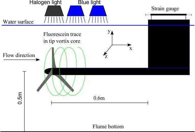
82 Fluorescein on tips - TSR 5

83 Fluorescein on tips -TSR 4

84 Fluorescein on tips - TSR 7

85 PIV set-up

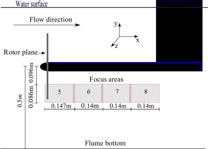


86 Focus areas

87 PIV, Mean(500) Axial Velocity, TSR 4-7

88 PIV, Mean Axial Velocity Urms TSR 4-7
89 PIV, Mean Axial Velocity U TSR
90 PIV, Phase ave., U-vel, TSR 6
 Uax")
91 PIV, Phase Average(100) Uax TSR 4-7

92 MEXICO PIV, Phase Ave., Uax


93 MEXICO PIV, Phase Ave., W
94 PIV, Tangentiel Vel, W-mean TSR 4-7

95 PIV, Phase ave., U-rms, TSR 4-7

96 PIV, U-vel, TSR 6 unfolded, 5deg/s
97 Expansion of the wake

98 PIV, U-vel, TSR 6 unfolded, 5deg/s


99 Rotation of the wake
100 Thrust measurements


101 Visualisation with upstream injection
102 Summary Experimental facilities were found useable Visualization captures dynamics of helical structures Full mapping of the mean flow in the wake at TSR 4-7 Wake expansion at different TSR s 3D mapping of the wake near the rotor plane Strain gauge measurements needs improvment Improvement of PIV data More measurements planed 2011 Out of plane vel. Upstream measurements Phase triggering
103 6 Simulations of backward swept blade 102 Risø-R-1769(EN)

104 Potential of fatigue and extreme load reductions on swept blades using HAWC2 David Verelst RISØ DTU
105 UPWIND Turbine: 5MW NREL Reference turbine by J. Jonkman et al (NREL 2009) Rating Configuration Control Drivetrain Rotor, Hub diameter Cut-in, Rated, Cut-out wind speed Cut-in, Rated rotor speed Rated tip speed Overhang, Shaft tilt, Precone 5 MW Upwind, 3 blades Variable speed, collective pitch High speed, Multiple-stage gearbox 126m, 3m 3 m/s, 11.4 m/s, 25 m/s 6.9, 12.1 RPM 80 m/s 5m, 0 deg, 0 deg 2 Risø DTU
106 Previous swept blade studies This presentation is based on a public Risø report: Load Consequences when Sweeping Blades A Case Study of a 5 MW Pitch Controlled Wind Turbine, D.R.S. Verelst, T.J. Larsen, 2010 Sandia Night & Karver STAR blade Objective: increase energy consumption on Zond 750 turbine for low wind speed sites (average wind speed around 5.8 m/s) Zond 750 is a variable speed pitch controlled machine Larger swept blade but load level maintained (blade root bending moments) Increased energy capture in below rated conditions. Full scale tests shows energy increase of 10-12% Thomas Ashwill et al., Development of the Swept Twist Adaptive Rotor (STAR) Blade, AIAA ). 3 Risø DTU
107 Why sweep? Sweep adds a geometric coupling between bending and twist deformations of the blade Increase blade size while maintaining blade root bending moment load levels. As a result, increased energy capture due to larger rotor For backward sweep, pitch to feather decreases angle of attack variations over one rotor revolution (cfr. turbulence, shear): passive cyclic pitch Preliminary results indicate decreased yawing moments (work in progress for EWEC 2011) 4 Risø DTU
108 Methodology 5 sweep curve exponents combined with 24 tip offsets = (ref.) blade variants 2 different controller implementations (Risø and NREL) Steady wind speeds (4..26 m/s, 1m/s steps) Turbulent wind speeds (4..26 m/s, 2m/s steps, 10 min series) same seed number, TI=0.18 Equivalent loads for standard wind speed distribution and 20 years 5 Risø DTU
109 Blade structural characteristics Start sweep curve at 14.35m (blade radial pos) Torsional stiffness Flapwise stiffness Edgewise stiffness Sweep starting point Blade root Blade tip 6 Risø DTU
110 Equivalent loads blade flap Forward sweep No sweep Backward sweep 7 Risø DTU
111 Equivalent loads blade edge Forward sweep No sweep Backward sweep 8 Risø DTU

112 Equivalent loads blade torsion Forward sweep No sweep Backward sweep 9 Risø DTU
113 Extreme loads blade flap Forward sweep No sweep Backward sweep 10 Risø DTU
114 Extreme loads blade edge Forward sweep No sweep Backward sweep 11 Risø DTU
115 Overview of Approximate Load Consequences 12 Risø DTU
116 Energy Yield steady wind Forward sweep No sweep Backward sweep 13 Risø DTU
117 Power Curve At rated wind speed and above the power is not affected Power output [kw] Reduced power output below rated for swept back blade 14 Risø DTU
118 Tip Twist and Pitch Angle To compensate for the changed twist (lower), pitch setting for the backward swept blade is lower and starts later (at higher wind speed) Zero pitch angle not changed Blade twist at the tip is decreased for the backward sweep wrt to the unswept blade 15 Risø DTU
119 Conclusions Forward sweep (pitch to stall): Edge- and flap-wise blade loading increases Pitch control induced instabilities Backward sweep (pitch to feather): Flap-wise blade loading decreased, edge-wise increased Blade root torsional moment increased significantly Decreased tower and shaft loadings Sensitive for sweep shape (exponent) and controller Passive load shedding mechanism is expected to be relevant for even larger wind turbines 16 Risø DTU
120 7 Eigenvalue analysis of backward swept blades Risø-R-1769(EN) 119
121 Aeroelastic modal analysis of backward swept blades using HAWCStab2 Morten Hartvig Hansen Old findings: - Lower flapwise loads for backward sweep New findings: - Lower flapwise damping but higher flapwise stiffness - Flutter limit decreases
 blade, In Proc.")

122 Field test at Sandia Nat. Lab. Ashwil et al., Development of the swept twist adaptive rotor (STAR) blade, In Proc. of the 48th AIAA Aerospace Sciences Meeting, 2010: 26.1 m STAR prototype blade can increase the annual energy capture by 10-12% compared to a baseline 23.5 m blade without increasing the blade root bending moments Sandia Report SAND Risø DTU, Technical University of Denmark Aeroelastic Workshop, January


123 What is HAWCStab2? Linear aeroelastic model for eigenvalue and frequency domain analysis of wind turbines and blades Nonlinear kinematics based on corotational elements with possibility of bearings e.g. generator and pitch. Uniform inflow to give a stationary steady state. Analytical linearization about the stationary steady state. Unsteady aerodynamics based on Leishman-Beddoes. A two state (per calc. point) model of dynamic inflow will soon be included. 3 Risø DTU, Technical University of Denmark Aeroelastic Workshop, January
124 Nonlinear kinematic formulation for blade Unloaded backward swept blade Blade in steady state equilibrium Aerodynamic calculation point on element number k Plane of airfoil chord coordinate system Updated element coordinate system of element number k Element positions and orientations Rotation Wind 4 Risø DTU, Technical University of Denmark Aeroelastic Workshop, January
125 Nonlinear steady state 5 Risø DTU, Technical University of Denmark Aeroelastic Workshop, January
126 Linear equations for small vibrations about the nonlinear steady state Coupling to structural states = elastic (and bearing) degrees of freedom = aerodynamic state variables = forces due to actuators and wind disturbance 6 Risø DTU, Technical University of Denmark Aeroelastic Workshop, January
127 Backward swept blades Baseline NREL 61.5m with CG at EA 7 Risø DTU, Technical University of Denmark Aeroelastic Workshop, January
128 Steady state power and pitch angle & torque Power Pitch angle Relative power diff. Pitch torque 8 Risø DTU, Technical University of Denmark Aeroelastic Workshop, January
129 Steady state thrust and tip deflection Tip deflection downwind Thrust Spanwise tip deflection Flapwise blade moment 9 Risø DTU, Technical University of Denmark Aeroelastic Workshop, January
130 Modal frequencies and damping 1 st flap 10 Risø DTU, Technical University of Denmark Aeroelastic Workshop, January
131 Mode shapes at 12 m/s 1 st flap 11 Risø DTU, Technical University of Denmark Aeroelastic Workshop, January

132 Blade section motion at 75% radius 1 st flap Downwind 12 Risø DTU, Technical University of Denmark Aeroelastic Workshop, January
133 Flapwise blade root moment 13 Risø DTU, Technical University of Denmark Aeroelastic Workshop, January
134 Edgewise blade root moment 14 Risø DTU, Technical University of Denmark Aeroelastic Workshop, January
135 Conclusions Backward swept blades twist towards feathering for flapwise bending in both structural and aeroelastic first flapwise bending modes This structural coupling of bending and torsion leads to higher aeroelastic modal frequency and lower aeroelastic damping of this mode The increased flapwise frequency of a backward swept blade is caused by added aerodynamic flapwise stiffness due to the twisting towards feathering when bending downwind This increased flapwise stiffness lowers the frequency response of backward swept blades at frequencies below the first flapwise frequency which can explain the reduced fatigue loads observed in previous studies The previously reported slight increase in edgewise blade root loads of backward swept blades can be explained by a slight reduction of aeroelastic damping of the first edgewise bending mode 15 Risø DTU, Technical University of Denmark Aeroelastic Workshop, January

136 Flutter test case Typical Section analogy HAWCStab2 model section stiff & massless beam small element flexible in flap & torsion 16 Risø DTU, Technical University of Denmark Aeroelastic Workshop, January

137 Lowest damped modes for 0 deg pitch and increasing relative speed ( ) Second flap Second torsion 17 Risø DTU, Technical University of Denmark Aeroelastic Workshop, January
138 8 Aeroelastic rotor design minimizing the loads Risø-R-1769(EN) 137
139 Aeroelastic rotor design minimizing the loads Mads Døssing, Christian Bak
140 Outline Background Simplified structural model Simplified fatigue model Influence of wide/slender blade on loads Optimization procedure Blade with DU airfoils (NREL 5MW) Blade with Risø-B1 airfoils (NREL 5MW) Conclusions 2 Risø DTU, Technical University of Denmark Aeroelastic Workshop 27. January 2011
141 Background Design of rotors purely based on aerodynamics have been carried out several times e.g. by Johansen et al. Design of rotors and the influence on loads have been investigated e.g. by Fuglsang in Reasearch in Aeroelasticity, EFP2002. However, constant structural layout was assumed. Also, design of rotors and the influence on loads have been investigated e.g. by Fuglsang et al in the EU project SITEOPT. However, structural correlation to rotor design was very simple. In this work more advanced models (however still simple) are developed to take into account mass and stiffness variations 3 Risø DTU, Technical University of Denmark Aeroelastic Workshop 27. January 2011
142 Simplified structural model 4 Risø DTU, Technical University of Denmark Aeroelastic Workshop 27 January 2011
143 Simplified structural model 5 Risø DTU, Technical University of Denmark Aeroelastic Workshop 27 January 2011
144 Simplified fatigue model 6 Risø DTU, Technical University of Denmark Aeroelastic Workshop 27 January 2011
145 Influence of wide/slender blade on loads 7 Risø DTU, Technical University of Denmark Aeroelastic Workshop 27 January 2011
146 Optimization procedure Optimization using steady state aerodynamic design and simplified fatigue model to reduced blade root flap fatigue load. Constraints on power and blade mass in design point (design point: 11m/s i.e. at rated wind speed for load reduction) Optimization using aeroelastic computations (HAWC2) with reduced number of design load cases to reduce blade root flap fatigue load. Constraints on power and blade mass in design point (design point: 10m/s ) The load cases should as far as possible be controller independent No power optimization 8 Risø DTU, Technical University of Denmark Aeroelastic Workshop 27. January 2011
147 Blade with DU airfoils (NREL 5MW) 9 Risø DTU, Technical University of Denmark Aeroelastic Workshop 27 January 2011
148 Blade with DU airfoils (NREL 5MW) 10 Risø DTU, Technical University of Denmark Aeroelastic Workshop 27 January 2011
149 Blade with Risø-B1 airfoils (NREL 5MW) 11 Risø DTU, Technical University of Denmark Aeroelastic Workshop 27 January 2011
150 Blade with Risø-B1 airfoils (NREL 5MW) 12 Risø DTU, Technical University of Denmark Aeroelastic Workshop 27 January 2011
151 Comparing blades 13 Risø DTU, Technical University of Denmark Aeroelastic Workshop 27. January 2011
152 Conclusions A simplified structural model has been formulated Comparison to existing blades show good agreement A simplified fatigue model has been formulated Comparison to aeroelastic calculations show good agreement Slender blades show lower loads Design with DU airfoils showed 3.3% reduction in fatigue loads 2.4% reduction in mass 1.4% reduction in AEP Design with Risø B1 airfoils showed 12.1% reduction in fatigue loads 5.1% reduction in mass 1.8% reduction in AEP 14 Risø DTU, Technical University of Denmark Aeroelastic Workshop 27. January 2011
153 9 A small study of flat back airfoils 152 Risø-R-1769(EN)
154 A Small Study of Flatback Airfoils Niels N. Sørensen Wind Energy Division Risø DTU RISØ-DTU,
155 Outline 1 Introduction 2 Flow solver settings 3 Grid Generation 4 Evaluation of Performance, 2D 5 3D Investigation 6 Parametric Study, 2D 7 Conclusion and Further Work 2 of 25 Niels N. Sørensen, Risø DTU A Small Study of Flatback Airfoils
156 Introduction Background Why are flatback airfoils interesting for rotor root design They may be desirable from a structural point of view They are claimed to be more roughness insensitive They can provide relatively high lift ( Cl > 2) The drag penalty of the thick trailing edge may not be important at the inboard sections They are sometimes claimed to be more efficient than traditional truncated airfoils FB FB FB FX 77-W-343 FX 77-W-400 FX 77-W of 25 Niels N. Sørensen, Risø DTU A Small Study of Flatback Airfoils
157 Introduction Challenges What problems must be foreseen when designing flatback airfoils, designed for the root section where the thickness is larger than 30% Typical design codes as the Xfoil code will eventually fail to give answers due to the trailing edge thickness The validity of CFD codes for these airfoils must be checked Wind tunnel testing of thick airfoils at high Re and AOA may be difficult What should the design philosophy be How will the flatback airfoils work during operational conditions How will the 3D effects often referred to as Stall Delay influence the performance How are there dynamical behaviour in stall 4 of 25 Niels N. Sørensen, Risø DTU A Small Study of Flatback Airfoils
158 Introduction Present Study The present study will not answer all these questions, but is the first step towards the design and testing of a flatback airfoil. We will evaluate the capability of our in-house CFD solver (EllipSys) to predict flatback and truncated airfoils We will briefly investigate possible wall junction problems for thick airfoils in tunnels We will do a small parametric study of possible ways to generate truncated airfoils 5 of 25 Niels N. Sørensen, Risø DTU A Small Study of Flatback Airfoils
159 Flow solver settings EllipSys2D/3D Two dimensional simulations and a few three dimensional simulations are performed C Both steady and transient runs t = t U = For the 2D simulations we use both fully turbulent and transitional computations based on the k ω SST model For the 3D simulations we use a so called Delayed Detached Eddy Simulation technique based on the SST model, along with the transition modeling Transition modeling is based on the γ Re θ model The diffusive terms are model using central differences In 2D the third order accurate QUICK scheme is used for the convective terms In 3D a hybrid fourth order central/quick scheme is used to resolve the DES areas 6 of 25 Niels N. Sørensen, Risø DTU A Small Study of Flatback Airfoils
160 Grid Generation Grid Generation 2D All grids are generated with the hyperbolic grid generation code HypGrid2D The grid has 320 cells in chordwise direction, and 128 cells in the wall normal direction The height of the first cell is Chord The outer boundary are placed 45 Chords away from the airfoil 7 of 25 Niels N. Sørensen, Risø DTU A Small Study of Flatback Airfoils
161 Grid Generation Grid Generation 3D All grids are generated with the hyperbolic grid generation code HypGrid2D The inner O-grid has 320 cells in chordwise direction, and 128 cells in the wall normal direction The inner O-grid is embedded in a stretched square grid The height of the first cell is Chord The upstream and downstream boundaries are placed 9 chords away, while the bottom and lid are approximately 5 chords away In the spanwise direction, the domain is 1 Chord long and 128 cells are used 8 of 25 Niels N. Sørensen, Risø DTU A Small Study of Flatback Airfoils
162 Grid Generation Grid Generation 3D (2) 9 of 25 Niels N. Sørensen, Risø DTU A Small Study of Flatback Airfoils
163 Grid Generation Grid Generation 3D (2) 9 of 25 Niels N. Sørensen, Risø DTU A Small Study of Flatback Airfoils

164 Grid Generation Grid Generation 3D (2) 9 of 25 Niels N. Sørensen, Risø DTU A Small Study of Flatback Airfoils
165 Evaluation of Performance, 2D FX-77-W-343 Conditions: Re = , free transition Data from University of Stuttgart 10 of 25 Niels N. Sørensen, Risø DTU A Small Study of Flatback Airfoils
166 Evaluation of Performance, 2D FX-77-W-343 Conditions: Re = , free transition Data from University of Stuttgart 2.5 FX-77-W-343, Re=3 mill 2 FX-77-W-343, Re=3 mill C l C l Stuttgart EllipSys, ST EllipSys, US AOA [deg] C d Stuttgart EllipSys, ST EllipSys, US FX-77-W-343, Re=3 mill Stuttgart EllipSys, ST EllipSys, US C m of 25 Niels N. Sørensen, Risø DTU AOA [deg] A Small Study of Flatback Airfoils
167 Evaluation of Performance, 2D FX-77-W-400 Conditions: Re = , free transition 11 of 25 Niels N. Sørensen, Risø DTU A Small Study of Flatback Airfoils
168 Evaluation of Performance, 2D FX-77-W-400 Conditions: Re = , free transition 2 FX-77-W-400, Re=4 mill 2 FX-77-W-400, Re=4 mill C l C l Stuttgart EllipSys, ST EllipSys, US AOA [deg] 0 Stuttgart EllipSys, ST EllipSys, US C d FX-77-W-400, Re=4 mill Stuttgart EllipSys, ST EllipSys, US C m of 25 Niels N. Sørensen, Risø DTU AOA [deg] A Small Study of Flatback Airfoils
169 Evaluation of Performance, 2D FX-77-W-500 Conditions: Re = , free transition 12 of 25 Niels N. Sørensen, Risø DTU A Small Study of Flatback Airfoils
170 Evaluation of Performance, 2D FX-77-W-500 Conditions: Re = , free transition 3 FX-77-W-500, Re=2.75 mill 3 FX-77-W-500, Re=2.75 mill C l 1 C l Stuttgart EllipSys, ST EllipSys, US AOA [deg] 0 Stuttgart EllipSys, ST EllipSys, US C d 12 of 25 Niels N. Sørensen, Risø DTU A Small Study of Flatback Airfoils
171 Evaluation of Performance, 2D FB Conditions: Re = , free transition left and fixed right Data from University of California (UC Davis) 13 of 25 Niels N. Sørensen, Risø DTU A Small Study of Flatback Airfoils
172 Evaluation of Performance, 2D FB Conditions: Re = , free transition left and fixed right Data from University of California (UC Davis) C l FB , Re= Measured, Free EllipSys, Free, ST EllipSys, Free, US C l FB , Re= Measured, Fixed EllipSys, Fixed, ST EllipSys, Fixed, US AOA [deg] AOA [deg] 13 of 25 Niels N. Sørensen, Risø DTU A Small Study of Flatback Airfoils
173 Evaluation of Performance, 2D FB Conditions: Re = , free transition left and fixed right Data from University of California (UC Davis) FB , Re= Measured, Free EllipSys, Free, ST EllipSys, Free, US FB , Re= Measured, Fixed EllipSys, Fixed, ST EllipSys, Fixed, US C d 0.15 C d AOA [deg] AOA [deg] 13 of 25 Niels N. Sørensen, Risø DTU A Small Study of Flatback Airfoils
174 Evaluation of Performance, 2D FB Conditions: Re = , free transition left and fixed right 14 of 25 Niels N. Sørensen, Risø DTU A Small Study of Flatback Airfoils
175 Evaluation of Performance, 2D FB Conditions: Re = , free transition left and fixed right FB , Re= Measured, free EllipSys, Free, ST EllipSys, Free, US FB , Re= Measured, Fixed EllipSys, Fixed, ST EllipSys, Fixed, US C l 1 C l AOA [deg] AOA [deg] 14 of 25 Niels N. Sørensen, Risø DTU A Small Study of Flatback Airfoils
176 Evaluation of Performance, 2D FB Conditions: Re = , free transition left and fixed right C d FB , Re= Measured, free EllipSys, Free, ST EllipSys, Free, US C d FB , Re= Measured, Fixed EllipSys, Fixed, ST EllipSys, Fixed, US AOA [deg] AOA [deg] 14 of 25 Niels N. Sørensen, Risø DTU A Small Study of Flatback Airfoils
177 Evaluation of Performance, 2D FB Conditions: Re = , free transition left and fixed right 15 of 25 Niels N. Sørensen, Risø DTU A Small Study of Flatback Airfoils
178 Evaluation of Performance, 2D FB Conditions: Re = , free transition left and fixed right FB , Re= Measured, free EllipSys, Free, ST EllipSys, Free, US FB , Re= Measured, Fixed EllipSys, Fixed, ST EllipSys, Fixed, US C l C l AOA [deg] AOA [deg] 15 of 25 Niels N. Sørensen, Risø DTU A Small Study of Flatback Airfoils
179 Evaluation of Performance, 2D FB Conditions: Re = , free transition left and fixed right C d FB , Re= Measured, free EllipSys, Free, ST EllipSys, Free, US C d FB , Re= Measured, Fixed EllipSys, Fixed, ST EllipSys, Fixed, US AOA [deg] AOA [deg] 15 of 25 Niels N. Sørensen, Risø DTU A Small Study of Flatback Airfoils
180 Evaluation of Performance, 2D FB-3500 Comparison of the three flat back airfoils FB , Re= Measured, Fixed EllipSys, Fixed, ST EllipSys, Fixed, US FB , Re= Measured, Fixed EllipSys, Fixed, ST EllipSys, Fixed, US C l 0.6 C l AOA [deg] AOA [deg] FB , Re= Measured, Fixed EllipSys, Fixed, ST EllipSys, Fixed, US 1.5 C l of 25 Niels N. Sørensen, Risø DTU A25Small Study of Flatback Airfoils AOA [deg]
181 Evaluation of Performance, 2D FB-3500 Comparison of the three flat back airfoils C d FB , Re= Measured, Fixed EllipSys, Fixed, ST EllipSys, Fixed, US C d FB , Re= Measured, Fixed EllipSys, Fixed, ST EllipSys, Fixed, US AOA [deg] AOA [deg] FB , Re= Measured, Fixed EllipSys, Fixed, ST EllipSys, Fixed, US C d of 25 Niels N. Sørensen, Risø DTU 0.1 A Small Study of Flatback Airfoils
182 Evaluation of Performance, 2D Resume of performance evaluation The solver is capable of reproducing effect of changing from free to fixed transition Generally the drag is well captured for the flatback airfoils, (it is mainly pressure based) In all 2D cases the steady state results are closer to the measured lift (slightly surprising) The tendency of the drag is not as clear, in some cases the unsteady agrees better We can use CFD to compare the quality of different designs 17 of 25 Niels N. Sørensen, Risø DTU A Small Study of Flatback Airfoils

183 3D Investigation How will the flatback airfoils behave in the tunnel Is the fact that 2D steady computations perform better due to some 2D artifact Can 3D provide improved insight? 18 of 25 Niels N. Sørensen, Risø DTU A Small Study of Flatback Airfoils

184 3D Investigation 3D Flow Patterns Operational conditions Re = Free transition Span length is equal to 2 chords AOA= 5 deg. 19 of 25 Niels N. Sørensen, Risø DTU A Small Study of Flatback Airfoils

185 3D Investigation 3D Flow Patterns Operational conditions Re = Free transition Span length is equal to 2 chords AOA= 10 deg. 19 of 25 Niels N. Sørensen, Risø DTU A Small Study of Flatback Airfoils
186 3D Investigation 3D Flow Patterns Operational conditions Re = Free transition Span length is equal to 2 chords AOA= 15 deg. 19 of 25 Niels N. Sørensen, Risø DTU A Small Study of Flatback Airfoils
187 3D Investigation 3D Flow Patterns Operational conditions Re = Free transition Span length is equal to 2 chords AOA= 17 deg. 19 of 25 Niels N. Sørensen, Risø DTU A Small Study of Flatback Airfoils

188 3D Investigation 3D Flow Patterns Operational conditions Re = Free transition Span length is equal to 2 chords AOA= 19 deg. 19 of 25 Niels N. Sørensen, Risø DTU A Small Study of Flatback Airfoils
189 3D Investigation Comparison between different techniques 3 FB , Re= , Free transition C l Measured 3D, UN, Free 0 2D, UN, Free 2D, ST, Free 3D, UN, no-wall AOA [deg] 20 of 25 3D unsteady comp. agrees better than 2D unsteady comp By coincidence 2D steady captures nearly the same value as 3D unsteady Niels N. Sørensen, Risø DTU A Small Study of Flatback Airfoils
190 3D Investigation Comparison between different techniques Measured 3D, UN, Free 2D, UN, Free 2D, ST, Free 3D, UN, no-wall FB , Re= , Free transition 0.35 C d AOA [deg] 20 of 25 3D unsteady comp. agrees better than 2D unsteady comp By coincidence 2D steady captures nearly the same value as 3D unsteady Niels N. Sørensen, Risø DTU A Small Study of Flatback Airfoils
191 3D Investigation Resume of 3D computations Results for the FB Airfoil At low angles of attack (<17 degrees) the inclusion of the wall junction only caused minor changes At high angle of attack (>17 degrees) the wall junction induces severe 3D flow and low lift Tunnel effects may play an important role in experimental and computational evaluation of FB airfoils 21 of 25 Niels N. Sørensen, Risø DTU A Small Study of Flatback Airfoils
192 Parametric Study, 2D Flatbacking the DU-97-W-300 Operational conditions, Re = , Free transition Opening the trailing edge, towards suction or pressure side y/c x/c Original y/c x/c Original Suction-00, Pressure-30 y/c x/c Original Suction-10, Pressure-20 y/c y/c x/c x/c Original Suction-20, Pressure-10 Original Suction-30, Pressure of 25 Niels N. Sørensen, Risø DTU A Small Study of Flatback Airfoils
193 Parametric Study, 2D Airfoil performance Operational conditions, Re = , Free transition All generated flatback airfoils have higher max lift C l Original Suction-00, Pressure Suction-10, Pressure-20 Suction-20, Pressure-10 Suction-30, Pressure AOA [degrees] 23 of 25 Niels N. Sørensen, Risø DTU A Small Study of Flatback Airfoils
194 Parametric Study, 2D Airfoil performance Operational conditions, Re = , Free transition All generated flatback airfoils have higher drag C l Original Suction-00, Pressure Suction-10, Pressure-20 Suction-20, Pressure-10-1 Suction-30, Pressure C d 23 of 25 Niels N. Sørensen, Risø DTU A Small Study of Flatback Airfoils
195 Parametric Study, 2D Resume of parametric study The flatback version has a higher lift The most efficient one is the one opened solely to the pressure side The drag increases for all airfoils, and generally to the same level 24 of 25 Niels N. Sørensen, Risø DTU A Small Study of Flatback Airfoils
196 Conclusion and Further Work Conclusions: We believe that both the 2D/3D CFD solvers can be used to evaluate flatback airfoils Computations indicate that high lift can be obtained, and the exp. of FB indicates that this may be true It is clear from the parametric study that to increase the lift the opening of the trailing edge most be done towards the pressure side Further work: We need to design an airfoil for tunnel test We need to evaluate the dynamic performance (3D dynamic stall comp.) We need to evaluate the performance of flatback in rotational environment Noise issues from the vortex shedding at the thick trailing edge 25 of 25 Niels N. Sørensen, Risø DTU A Small Study of Flatback Airfoils
197 10 Status of airfoil design 196 Risø-R-1769(EN)


198 Status of airfoil design and plans for wind tunnel tests of new thick airfoils Christian Bak, Mac Gaunaa, Niels Sørensen, Franck Bertagnolio


199 Background Airfoils designed and tested in the past Risø-A1: Risø-P: Risø-B1: Risø-C2: High cl-cd-ratio, good stalling characteristics, good roughness sensitivity High cl-cd-ratio, very good stalling characteristics, good roughness sensitivity Medium cl-cd-ratio, high lift, very good roughness insensitivity High cl-cd ratio, high lift, very good roughness insensitivity, high moment of resistance Stall regulation, t/c 12% to 24% Pitch regulation, t/c 15% to 24% Pitch reg var speed, t/c 15% to 53% Pitch reg var speed, t/c 15% to 36% 2 Risø DTU, Technical University of Denmark Aeroelastic Workshop 27/01/2011
200 Status Recent designs New aspects taken into account: Trailing edge noise (mainly thin and medium thick airfoils) TNO model Glegg model Thick airfoils with high lift and low sensitivity to roughness Flat back airfoils Multielement airfoils 3 Risø DTU, Technical University of Denmark Aeroelastic Workshop 27/01/2011
201 Thick multielement airfoils Slat size investigation Big slats 0.3c and 0.5c Small slats 0.1c and 0.2c 4 Risø DTU, Technical University of Denmark Aeroelastic Workshop 27/01/2011

202 Thick multielement airfoils Slat size investigation 5 Risø DTU, Technical University of Denmark Aeroelastic Workshop 27/01/2011
Steady State Comparisons HAWC2 v12.2 vs HAWCStab2 v2.12
 Downloaded from orbit.dtu.dk on: Jan 29, 219 Steady State Comparisons v12.2 vs v2.12 Verelst, David Robert; Hansen, Morten Hartvig; Pirrung, Georg Publication date: 216 Document Version Publisher's PDF,
Some effects of large blade deflections on aeroelastic stability
 47th AIAA Aerospace Sciences Meeting Including The New Horizons Forum and Aerospace Exposition 5-8 January 29, Orlando, Florida AIAA 29-839 Some effects of large blade deflections on aeroelastic stability
A comparison study of the two-bladed partial pitch turbine during normal operation and an extreme gust conditions
 Downloaded from orbit.dtu.dk on: Jul 12, 2018 A comparison study of the two-bladed partial pitch turbine during normal operation and an extreme gust conditions Kim, Taeseong; Pedersen, Mads Mølgaard; Larsen,
Using Pretwist to Reduce Power Loss of Bend-Twist Coupled Blades
 Downloaded from orbit.dtu.dk on: Jan 2, 219 Using Pretwist to Reduce Power Loss of Bend-Twist Coupled Blades Stäblein, Alexander; Tibaldi, Carlo; Hansen, Morten Hartvig Published in: Proceedings of the
Prediction of airfoil performance at high Reynolds numbers.
 Downloaded from orbit.dtu.dk on: Nov 04, 2018 Prediction of airfoil performance at high Reynolds numbers. Sørensen, Niels N.; Zahle, Frederik; Michelsen, Jess Publication date: 2014 Document Version Publisher's
Sensitivity of Key Parameters in Aerodynamic Wind Turbine Rotor Design on Power and Energy Performance
 Journal of Physics: Conference Series Sensitivity of Key Parameters in Aerodynamic Wind Turbine Rotor Design on Power and Energy Performance To cite this article: Christian Bak 007 J. Phys.: Conf. Ser.
Research in Aeroelasticity EFP-2005
 Risø-R-1559(EN) Research in Aeroelasticity EFP-005 Edited by Christian Bak Risø National Laboratory Roskilde Denmark May 006 Author: Edited by Christian Bak Title: Research in Aeroelasticity EFP-005 Department:
Aeroelastic effects of large blade deflections for wind turbines
 Aeroelastic effects of large blade deflections for wind turbines Torben J. Larsen Anders M. Hansen Risoe, National Laboratory Risoe, National Laboratory P.O. Box 49, 4 Roskilde, Denmark P.O. Box 49, 4
Validation of the actuator line and disc techniques using the New MEXICO measurements
 Downloaded from orbit.dtu.dk on: Dec, 7 Validation of the actuator line and disc techniques using the New MEXICO measurements Sarmast, Sasan; Shen, Wen Z.; Zhu, Wei Jun; Mikkelsen, Robert Flemming; Breton,
Actuator Surface Model for Wind Turbine Flow Computations
 Actuator Surface Model for Wind Turbine Flow Computations Wen Zhong Shen* 1, Jens Nørkær Sørensen 1 and Jian Hui Zhang 1 Department of Mechanical Engineering, Technical University of Denmark, Building
CHAPTER 4 OPTIMIZATION OF COEFFICIENT OF LIFT, DRAG AND POWER - AN ITERATIVE APPROACH
 82 CHAPTER 4 OPTIMIZATION OF COEFFICIENT OF LIFT, DRAG AND POWER - AN ITERATIVE APPROACH The coefficient of lift, drag and power for wind turbine rotor is optimized using an iterative approach. The coefficient
STRUCTURAL PITCH FOR A PITCH-TO-VANE CONTROLLED WIND TURBINE ROTOR
 ECN-C--03-087 STRUCTURAL PITCH FOR A PITCH-TO-VANE CONTROLLED WIND TURBINE ROTOR DAMPBLADE project, task 3.4: Design application, sensitivity analysis and aeroelastic tailoring C. Lindenburg M.H. Hansen
Identification of structural non-linearities due to large deflections on a 5MW wind turbine blade
 Identification of structural non-linearities due to large deflections on a 5MW wind turbine blade V. A. Riziotis and S. G. Voutsinas National Technical University of Athens 9 Heroon Polytechniou str.,
A comparison study of the two-bladed partial pitch turbine during normal operation and an extreme gust conditions
 Journal of Physics: Conference Series OPEN ACCESS A comparison study of the two-bladed partial pitch turbine during normal operation and an extreme gust conditions To cite this article: T Kim et al 2014
Mechanical Engineering for Renewable Energy Systems. Dr. Digby Symons. Wind Turbine Blade Design
 ENGINEERING TRIPOS PART IB PAPER 8 ELECTIVE () Mechanical Engineering for Renewable Energy Systems Dr. Digby Symons Wind Turbine Blade Design Student Handout CONTENTS 1 Introduction... 3 Wind Turbine Blade
Flap testing on the rotating test rig in the INDUFLAP project
 Downloaded from orbit.dtu.dk on: Dec 26, 2018 Flap testing on the rotating test rig in the INDUFLAP project Barlas, Athanasios; Aagaard Madsen, Helge; Enevoldsen, Karen; Klemmensen, Kasper Publication
Implementation of an advanced beam model in BHawC
 Journal of Physics: Conference Series PAPER OPEN ACCESS Implementation of an advanced beam model in BHawC To cite this article: P J Couturier and P F Skjoldan 28 J. Phys.: Conf. Ser. 37 625 Related content
Wake decay constant for the infinite wind turbine array Application of asymptotic speed deficit concept to existing engineering wake model
 Downloaded from orbit.dtu.dk on: Jul 22, 208 Wake decay constant for the infinite wind turbine array Application of asymptotic speed deficit concept to existing engineering wake model Rathmann, Ole Steen;
Dynamics of a hydraulic pitch system
 Downloaded from orbit.dtu.dk on: Dec 1, 218 Dynamics of a hydraulic pitch system Hansen, Morten Hartvig; Kallesøe, Bjarne Skovmose Published in: Research in aeroelasticity EFP-26 Publication date: 27 Document
Aerodynamic Performance 1. Figure 1: Flowfield of a Wind Turbine and Actuator disc. Table 1: Properties of the actuator disk.
 Aerodynamic Performance 1 1 Momentum Theory Figure 1: Flowfield of a Wind Turbine and Actuator disc. Table 1: Properties of the actuator disk. 1. The flow is perfect fluid, steady, and incompressible.
Comparison of design methods for turbines in wake
 Downloaded from orbit.dtu.dk on: Dec 7, 27 Comparison of design methods for turbines in wake Larsen, Torben J.; Aagaard Madsen, Helge; Larsen, Gunner Chr. Published in: Research in aeroelasticity EFP-27
Effect of linear and non-linear blade modelling techniques on simulated fatigue and extreme loads using Bladed
 Journal of Physics: Conference Series PAPER OPEN ACCESS Effect of linear and non-linear blade modelling techniques on simulated fatigue and extreme loads using Bladed To cite this article: Alec Beardsell
Analysis of Counter-Rotating Wind Turbines
 Journal of Physics: Conference Series Analysis of Counter-Rotating Wind Turbines To cite this article: W Z Shen et al 7 J. Phys.: Conf. Ser. 75 3 View the article online for updates and enhancements. Related
Effect of Geometric Uncertainties on the Aerodynamic Characteristic of Offshore Wind Turbine Blades
 the Aerodynamic Offshore Wind, Henning Schmitt, Jörg R. Seume The Science of Making Torque from Wind 2012 October 9-11, 2012 Oldenburg, Germany 1. Motivation and 2. 3. 4. 5. Conclusions and Slide 2 / 12
Resolution of tower shadow models for downwind mounted rotors and its effects on the blade fatigue
 Journal of Physics: Conference Series OPEN ACCESS Resolution of tower shadow models for downwind mounted rotors and its effects on the blade fatigue To cite this article: M Reiso and M Muskulus 2014 J.
Performance and Equivalent Loads of Wind Turbines in Large Wind Farms.
 Performance and Equivalent Loads of Wind Turbines in Large Wind Farms. Søren Juhl Andersen 1, Jens Nørkær Sørensen, and Robert Mikkelsen May 30, 2017 Email: 1 sjan@dtu.dk Andersen Performance of Large
Numerical Study on Performance of Curved Wind Turbine Blade for Loads Reduction
 Numerical Study on Performance of Curved Wind Turbine Blade for Loads Reduction T. Maggio F. Grasso D.P. Coiro 13th International Conference Wind Engineering (ICWE13), 10-15 July 011, Amsterdam, the Netherlands.
Experimental and numerical investigation of 3D aerofoil characteristics on a MW wind turbine
 Downloaded from orbit.dtu.dk on: Jan, 9 erimental and numerical investigation of D aerofoil characteristics on a MW wind turbine Troldborg, Niels; Bak, Christian; Sørensen, Niels N.; Aagaard Madsen, Helge;
Advanced Load Alleviation for Wind Turbines using Adaptive Trailing Edge Flaps: Sensoring and Control. Risø-PhD-Report
 Advanced Load Alleviation for Wind Turbines using Adaptive Trailing Edge Flaps: Sensoring and Control Risø-PhD-Report Peter Bjørn Andersen Risø-PhD-61(EN) February 2010 Author: Peter Bjørn Andersen Title:
Large-eddy simulations for wind turbine blade: rotational augmentation and dynamic stall
 Large-eddy simulations for wind turbine blade: rotational augmentation and dynamic stall Y. Kim, I.P. Castro, and Z.T. Xie Introduction Wind turbines operate in the atmospheric boundary layer and their
A Procedure for Classification of Cup-Anemometers
 Downloaded from orbit.dtu.dk on: Dec, 17 A Procedure for Classification of Cup-Anemometers Friis Pedersen, Troels; Paulsen, Uwe Schmidt Published in: Proceedings of EWEC 97 Publication date: 1997 Link
Fatigue Reliability and Effective Turbulence Models in Wind Farms
 Downloaded from vbn.aau.dk on: marts 28, 2019 Aalborg Universitet Fatigue Reliability and Effective Turbulence Models in Wind Farms Sørensen, John Dalsgaard; Frandsen, S.; Tarp-Johansen, N.J. Published
Numerical Study on Performance of Innovative Wind Turbine Blade for Load Reduction
 Numerical Study on Performance of Innovative Wind Turbine Blade for Load Reduction T. Maggio F. Grasso D.P. Coiro This paper has been presented at the EWEA 011, Brussels, Belgium, 14-17 March 011 ECN-M-11-036
Multivariate Modelling of Extreme Load Combinations for Wind Turbines
 Downloaded from orbit.dtu.dk on: Oct 05, 2018 Multivariate Modelling of Extreme Load Combinations for Wind Turbines Dimitrov, Nikolay Krasimirov Published in: Proceedings of the 12th International Conference
Optimizing Reliability using BECAS - an Open-Source Cross Section Analysis Tool
 Downloaded from orbit.dtu.dk on: Dec 20, 2017 Optimizing Reliability using BECAS - an Open-Source Cross Section Analysis Tool Bitsche, Robert; Blasques, José Pedro Albergaria Amaral Publication date: 2012
θ α W Description of aero.m
 Description of aero.m Determination of the aerodynamic forces, moments and power by means of the blade element method; for known mean wind speed, induction factor etc. Simplifications: uniform flow (i.e.
VORTEX METHOD APPLICATION FOR AERODYNAMIC LOADS ON ROTOR BLADES
 EWEA 2013: Europe s Premier Wind Energy Event, Vienna, 4-7 February 2013 Figures 9, 10, 11, 12 and Table 1 corrected VORTEX METHOD APPLICATION FOR AERODYNAMIC LOADS ON ROTOR BLADES Hamidreza Abedi *, Lars
Detailed Load Analysis of the baseline 5MW DeepWind Concept
 Downloaded from orbit.dtu.dk on: Sep 15, 2018 Detailed Load Analysis of the baseline 5MW DeepWind Concept Verelst, David Robert; Aagaard Madsen, Helge; Kragh, Knud Abildgaard; Belloni, Federico Publication
Aeroelastic modelling of vertical axis wind turbines
 Aeroelastic modelling of vertical axis wind turbines Helge Aagaard Madsen Torben Juul Larsen Uwe Schmidt Paulsen Knud Abildgaard Kragh Section Aeroelastic Design Department of Wind Energy hama@dtu.dk Renewed
Structural Analysis of Wind Turbine Blades
 Structural Analysis of Wind Turbine Blades 2 nd Supergen Wind Educational Seminar Manchester 04 Mar 2009 Paul Bonnet Geoff Dutton Energy Research Unit Rutherford Appleton Laboratory STFC [1] Approach [2]
HARP_Opt: An Optimization Code for System Design of Axial Flow Turbines
 HARP_Opt: An Optimization Code for System Design of Axial Flow Turbines Marine and Hydrokinetic Instrumentation, Measurement, & Computer Modeling Workshop Broomfield, CO July 9-10, 2012 Danny Sale Northwest
Aeroelastic Stability of a 2D Airfoil Section equipped with a Trailing Edge Flap
 Downloaded from orbit.dtu.dk on: Apr 27, 2018 Aeroelastic Stability of a 2D Airfoil Section equipped with a Trailing Edge Flap Bergami, Leonardo Publication date: 2008 Document Version Publisher's PDF,
Aerodynamic Performance Assessment of Wind Turbine Composite Blades Using Corrected Blade Element Momentum Method
 Aerodynamic Performance Assessment of Wind Turbine Composite Blades Using Corrected Blade Element Momentum Method Chi Zhang 1) and *Hua-Peng Chen 2) 1), 2) Department of Engineering & Science, University
Simulation of Aeroelastic System with Aerodynamic Nonlinearity
 Simulation of Aeroelastic System with Aerodynamic Nonlinearity Muhamad Khairil Hafizi Mohd Zorkipli School of Aerospace Engineering, Universiti Sains Malaysia, Penang, MALAYSIA Norizham Abdul Razak School
Validation of Chaviaro Poulos and Hansen Stall Delay Model in the Case of Horizontal Axis Wind Turbine Operating in Yaw Conditions
 Energy and Power Engineering, 013, 5, 18-5 http://dx.doi.org/10.436/epe.013.51003 Published Online January 013 (http://www.scirp.org/journal/epe) Validation of Chaviaro Poulos and Hansen Stall Delay Model
Insight into Rotational Effects on a Wind Turbine Blade Using Navier Stokes Computations
 Energies 24, 7, 6798-6822; doi:.339/en76798 OPEN ACCESS energies ISSN 996-73 www.mdpi.com/journal/energies Article Insight into Rotational Effects on a Wind Turbine Blade Using Navier Stokes Computations
CFD RANS analysis of the rotational effects on the boundary layer of wind turbine blades
 Journal of Physics: Conference Series CFD RANS analysis of the rotational effects on the boundary layer of wind turbine blades To cite this article: Carlo E Carcangiu et al 27 J. Phys.: Conf. Ser. 75 23
Unsteady Viscous-Inviscid Interaction Technique for Wind Turbine Airfoils. PhD Thesis
 Unsteady Viscous-Inviscid Interaction Technique for Wind Turbine Airfoils PhD Thesis Néstor Ramos García DCAMM Special Report no. S7 April MEK-PHD -4 Unsteady Viscous-Inviscid Interaction Technique for
46320 Loads, Aerodynamics & Control of Wind Turbines. Aeroelastic analysis and design of the Turkispain wind turbine
 4632 Loads, Aerodynamics & Control of Wind Turbines Final Report: Aeroelastic analysis and design of the Turkispain wind turbine Authors: Emre Barlas, s988 Kaya Onur Dag, s58 Alfonso Pérez-Andújar, s672
Adaptive Control of Variable-Speed Variable-Pitch Wind Turbines Using RBF Neural Network
 Schulich School of Engineering Department of Mechanical and Manufacturing Engineering Adaptive Control of Variable-Speed Variable-Pitch Wind Turbines Using RBF Neural Network By: Hamidreza Jafarnejadsani,
Analysis of aeroelastic loads and their contributions to fatigue damage
 Journal of Physics: Conference Series OPEN ACCESS Analysis of aeroelastic loads and their contributions to fatigue damage To cite this article: L Bergami and M Gaunaa 214 J. Phys.: Conf. Ser. 555 127 View
Lecture 4: Wind energy
 ES427: The Natural Environment and Engineering Global warming and renewable energy Lecture 4: Wind energy Philip Davies Room A322 philip.davies@warwick.ac.uk 1 Overview of topic Wind resources Origin of
Aero-Hydro-Elastic Simulation Platform for Wave Energy Systems and floating Wind Turbines
 Downloaded from orbit.dtu.dk on: Nov 4, 218 Aero-Hydro-Elastic Simulation Platform for Wave Energy Systems and floating Wind Turbines Kallesøe, Bjarne Skovmose Publication date: 211 Document Version Publisher's
Turbulence modelling. Sørensen, Niels N. Publication date: Link back to DTU Orbit
 Downloaded from orbit.dtu.dk on: Dec 19, 2017 Turbulence modelling Sørensen, Niels N. Publication date: 2010 Link back to DTU Orbit Citation (APA): Sørensen, N. N. (2010). Turbulence modelling. Paper presented
arxiv: v1 [physics.flu-dyn] 11 Oct 2012
![arxiv: v1 [physics.flu-dyn] 11 Oct 2012](/thumbs/94/118739408.jpg "arxiv: v1 [physics.flu-dyn] 11 Oct 2012") Low-Order Modelling of Blade-Induced Turbulence for RANS Actuator Disk Computations of Wind and Tidal Turbines Takafumi Nishino and Richard H. J. Willden ariv:20.373v [physics.flu-dyn] Oct 202 Abstract
Low-Order Modelling of Blade-Induced Turbulence for RANS Actuator Disk Computations of Wind and Tidal Turbines Takafumi Nishino and Richard H. J. Willden ariv:20.373v [physics.flu-dyn] Oct 202 Abstract
Research on Dynamic Stall and Aerodynamic Characteristics of Wind Turbine 3D Rotational Blade
 Research on Dynamic Stall and Aerodynamic Characteristics of Wind Turbine 3D Rotational Blade HU Guo-yu, SUN Wen-lei, Dong Ping The School of Mechanical Engineering Xinjiang University Urumqi, Xinjiang,
Calculation of Wind Turbine Geometrical Angles Using Unsteady Blade Element Momentum (BEM)
") Proceedings Conference IGCRE 2014 16 Calculation of Wind Turbine Geometrical Angles Using Unsteady Blade Element Momentum (BEM) Adel Heydarabadipour, FarschadTorabi Abstract Converting wind kinetic energy
Proceedings Conference IGCRE 2014 16 Calculation of Wind Turbine Geometrical Angles Using Unsteady Blade Element Momentum (BEM) Adel Heydarabadipour, FarschadTorabi Abstract Converting wind kinetic energy
A Hybrid CFD/BEM Analysis of Flow Field around Wind Turbines
 A Hybrid CFD/BEM Analysis of Flow Field around Wind Turbines V. Esfahanian 1, A. Salavatipour 1, I. Harsini 2, A. Haghani 3, R. Pasandeh 1, and G. Ahmadi 4 1 Department of Mechanical Engineering, University
Stall-Induced Vibrations of the AVATAR Rotor Blade
 Journal of Physics: Conference Series PAPER OPEN ACCESS Stall-Induced Vibrations of the AVATAR Rotor Blade To cite this article: M Stettner et al 2016 J. Phys.: Conf. Ser. 753 042019 View the article online
Adjustment of k ω SST turbulence model for an improved prediction of stalls on wind turbine blades
 Adjustment of k ω SST turbulence model for an improved prediction of stalls on wind turbine blades Tawit Chitsomboon *, Chalothorn Thamthae School of Mechanical Engineering, Institute of Engineering, Suranaree
Aeroelastic Gust Response
 Aeroelastic Gust Response Civil Transport Aircraft - xxx Presented By: Fausto Gill Di Vincenzo 04-06-2012 What is Aeroelasticity? Aeroelasticity studies the effect of aerodynamic loads on flexible structures,
Indicial lift response function: an empirical relation for finitethickness airfoils, and effects on aeroelastic simulations
 Downloaded from orbit.dtu.dk on: Dec 05, 2018 Indicial lift response function: an empirical relation for finitethickness airfoils, and effects on aeroelastic simulations Bergami, Leonardo; Gaunaa, Mac;
Rotor reference axis
 Rotor reference axis So far we have used the same reference axis: Z aligned with the rotor shaft Y perpendicular to Z and along the blade (in the rotor plane). X in the rotor plane and perpendicular do
Dynamic Stall Modeling for Wind Turbines. M. A. Khan
 Dynamic Stall Modeling for Wind Turbines M. A. Khan Dynamic Stall Modeling for Wind Turbines by M. A. Khan to obtain the degree of Master of Science at the Delft University of Technology, to be defended
Performance and wake development behind two in-line and offset model wind turbines "Blind test" experiments and calculations
 Journal of Physics: Conference Series OPEN ACCESS Performance and wake development behind two in-line and offset model wind turbines "Blind test" experiments and calculations To cite this article: Lars
Unsteady structural behaviour of small wind turbine blades Samuel Evans Supervisor: A/Prof Philip Clausen
 Unsteady structural behaviour of small wind turbine blades Samuel Evans Supervisor: A/Prof Philip Clausen samuel.evans@uon.edu.au +61 2 492 16187 The University of Newcastle University Drive Callaghan
Implementing a Partitioned Algorithm for Fluid-Structure Interaction of Flexible Flapping Wings within Overture
 10 th Symposimum on Overset Composite Grids and Solution Technology, NASA Ames Research Center Moffett Field, California, USA 1 Implementing a Partitioned Algorithm for Fluid-Structure Interaction of Flexible
APPENDIX A. CONVENTIONS, REFERENCE SYSTEMS AND NOTATIONS
 APPENDIX A. CONVENTIONS, REFERENCE SYSTEMS AND NOTATIONS A.1 Introduction This appendix describes the sign conventions, reference systems and notations to be used within the IEA Annex XIV Field Rotor Aerodynamics.
Higher-order spectral modelling of the diffraction force around a vertical circular cylinder
 Downloaded from orbit.dtu.dk on: Apr 10, 2018 Higher-order spectral modelling of the diffraction force around a vertical circular cylinder Bredmose, Henrik; Andersen, Søren Juhl Publication date: 2017
What is the critical height of leading edge roughness for aerodynamics?
 Journal of Physics: Conference Series PAPER OPEN ACCESS What is the critical height of leading edge roughness for aerodynamics? To cite this article: Christian Bak et al 6 J. Phys.: Conf. Ser. 753 3 Recent
Numerical Investigation of Flow Control Feasibility with a Trailing Edge Flap
 Journal of Physics: Conference Series OPEN ACCESS Numerical Investigation of Flow Control Feasibility with a Trailing Edge Flap To cite this article: W J Zhu et al 2014 J. Phys.: Conf. Ser. 524 012102
MOTION SIMULATION AND STRESS AND STRAIN ANALYSIS OF ELASTIC WIND POWER GENERATORS *
 th 11 National Congress on Theoretical and Applied Mechanics, 2-5 Sept. 2009, Borovets, Bulgaria MOTION SIMULATION AND STRESS AND STRAIN ANALYSIS OF ELASTIC WIND POWER GENERATORS * EVTIM ZAHARIEV, EMIL
Numerical Validation of Floating Offshore Wind Turbine Scaled Rotor for Surge Motion
 1 2 3 4 5 6 7 8 9 10 11 12 13 14 15 16 17 18 19 20 21 22 23 24 25 26 27 28 29 30 31 32 33 34 35 36 37 38 39 40 41 42 43 44 45 46 Numerical Validation of Floating Offshore Wind Turbine Scaled Rotor for
Buffeting Response of Ultimate Loaded NREL 5MW Wind Turbine Blade using 3-dimensional CFD
 Buffeting Response of Ultimate Loaded NREL 5MW Wind Turbine Blade using 3-dimensional CFD *Byeong-Cheol Kim 1) and Youn-Ju Jeong 2) 1), 2) Structural Engineering Research Division, KICT, Il-San 411-712,
Aerodynamic Rotor Model for Unsteady Flow and Wake Impact
 Aerodynamic Rotor Model for Unsteady Flow and Wake Impact N. Bampalas, J. M. R. Graham Department of Aeronautics, Imperial College London, Prince Consort Road, London, SW7 2AZ June 28 1 (Steady Kutta condition)
Dynamic Characteristics of Wind Turbine Blade
 Dynamic Characteristics of Wind Turbine Blade Nitasha B. Chaudhari PG Scholar, Mechanical Engineering Department, MES College Of Engineering,Pune,India. Abstract this paper presents a review on the dynamic
arxiv: v1 [physics.flu-dyn] 13 Sep 2017
![arxiv: v1 [physics.flu-dyn] 13 Sep 2017](/thumbs/72/68048673.jpg "arxiv: v1 [physics.flu-dyn] 13 Sep 2017") arxiv:1709.04298v1 [physics.flu-dyn] 13 Sep 2017 Evaluation of different methods for determining the angle of attack on wind turbine blades with CFD results under axial inflow conditions H. Rahimi 1,2,
arxiv:1709.04298v1 [physics.flu-dyn] 13 Sep 2017 Evaluation of different methods for determining the angle of attack on wind turbine blades with CFD results under axial inflow conditions H. Rahimi 1,2,
Modelling of Vortex-Induced Loading on a Single- Blade Installation Setup
 Journal of Physics: Conference Series PAPER OPEN ACCESS Modelling of Vortex-Induced Loading on a Single- Blade Installation Setup To cite this article: Witold Skrzypiski et al 2016 J. Phys.: Conf. Ser.
Multidisciplinary Design Optimization Of A Helicopter Rotor Blade
 Ryerson University Digital Commons @ Ryerson Theses and dissertations 1-1-2010 Multidisciplinary Design Optimization Of A Helicopter Rotor Blade Michael G. Leahy Ryerson University Follow this and additional
Concept Testing of a Simple Floating Offshore Vertical Axis Wind Turbine
 Downloaded from orbit.dtu.dk on: Nov 18, 2018 Concept Testing of a Simple Floating Offshore Vertical Axis Wind Turbine Pedersen, Troels Friis; Schmidt Paulsen, Uwe; Aagaard Madsen, Helge; Nielsen, Per
MORPHING CHARACTERISTICS OF CHIRAL CORE AIRFOILS
 MORPHING CHARACTERISTICS OF CHIRAL CORE AIRFOILS Alessandro Spadoni, Massimo Ruzzene School of Aerospace Engineering Georgia Institute of Technology Atlanta GA - USA Chrystel Remillat, Fabrizio Scarpa,
Aero-Propulsive-Elastic Modeling Using OpenVSP
 Aero-Propulsive-Elastic Modeling Using OpenVSP August 8, 213 Kevin W. Reynolds Intelligent Systems Division, Code TI NASA Ames Research Center Our Introduction To OpenVSP Overview! Motivation and Background!
GyroRotor program : user manual
 GyroRotor program : user manual Jean Fourcade January 18, 2016 1 1 Introduction This document is the user manual of the GyroRotor program and will provide you with description of
Manhar Dhanak Florida Atlantic University Graduate Student: Zaqie Reza
 REPRESENTING PRESENCE OF SUBSURFACE CURRENT TURBINES IN OCEAN MODELS Manhar Dhanak Florida Atlantic University Graduate Student: Zaqie Reza 1 Momentum Equations 2 Effect of inclusion of Coriolis force
Gravo-Aeroelastic Scaling for Extreme-Scale Wind Turbines
 AIAA AVIATION Forum 5-9 June 2017, Denver, Colorado 35th AIAA Applied Aerodynamics Conference 10.2514/6.2017-4215 Gravo-Aeroelastic Scaling for Extreme-Scale Wind Turbines a c const. C C! c! E g G I Eric
Aeroelastic Stability of Suspension Bridges using CFD
 Aeroelastic Stability of Suspension Bridges using CFD Jesper STÆRDAHL Assistant professor Aalborg University Aalborg, Denmark Niels SØRENSEN Professor Aalborg University Aalborg, Denmark Søren NIELSEN
Wake modeling and simulation
 Wake modeling and simulation Gunner C. Larsen, Helge Aa. Madsen, Torben J. Larsen, and Niels Troldborg Risø-R-1653(EN) 1 Risø National Laboratory for Sustainable Energy Technical University of Denmark
1 Introduction. EU projects in German Dutch Wind Tunnel, DNW. 1.1 DATA project. 1.2 MEXICO project. J.G. Schepers
 EU projects in German Dutch Wind Tunnel, DNW J.G. Schepers Netherlands Energy Research Foundation P.O. Box 1, 1755 ZG Petten Tel: +31 224 564894 e-mail: schepers@ecn.nl 1 Introduction In this paper two
Radioactivity in the Risø District January-June 2014
 Downloaded from orbit.dtu.dk on: Dec 20, 2017 Radioactivity in the Risø District January-June 2014 Nielsen, Sven Poul; Andersson, Kasper Grann; Miller, Arne Publication date: 2014 Document Version Publisher's
Analysis of the effect of curtailment on power and fatigue loads of two aligned wind turbines using an actuator disc approach
 Journal of Physics: Conference Series OPEN ACCESS Analysis of the effect of curtailment on power and fatigue loads of two aligned wind turbines using an actuator disc approach To cite this article: Silke
Validation of Boundary Layer Winds from WRF Mesoscale Forecasts over Denmark
 Downloaded from orbit.dtu.dk on: Dec 14, 2018 Validation of Boundary Layer Winds from WRF Mesoscale Forecasts over Denmark Hahmann, Andrea N.; Pena Diaz, Alfredo Published in: EWEC 2010 Proceedings online
A Computational Aerodynamics Simulation of the NREL Phase II Rotor
 The Open Mechanical Engineering Journal, 2009, 3, 9-16 9 Open Access A Computational Aerodynamics Simulation of the NREL Phase II Rotor N.S. Tachos *,1, A.E. Filios *,2, D.P. Margaris 1 and J.K. Kaldellis
Wind Turbine Blade Analysis using the Blade Element Momentum Method. Version 1.0
 using the Blade Element Momentum Method. Version 1.0 Grant Ingram December 13, 2005 Copyright c) 2005 Grant Ingram, All Rights Reserved. 1 Contents 1 Introduction 5 2 Blade Element Momentum Theory 5 3
Fluid structure interaction of a parked wind turbine airfoil
 Fluid structure interaction of a parked wind turbine airfoil O. Guerri Centre de Développement des Energies Renouvelables BP 62, Bouzaréah, CP 16 34, Alger, Algérie o_guerri@yahoo.com Résumé Le problème
Radioactivity in the Risø District July-December 2013
 Downloaded from orbit.dtu.dk on: Jan 02, 2019 Radioactivity in the Risø District July-December 2013 Nielsen, Sven Poul; Andersson, Kasper Grann; Miller, Arne Publication date: 2014 Document Version Publisher's
Numerical Methods in Aerodynamics. Turbulence Modeling. Lecture 5: Turbulence modeling
 Turbulence Modeling Niels N. Sørensen Professor MSO, Ph.D. Department of Civil Engineering, Alborg University & Wind Energy Department, Risø National Laboratory Technical University of Denmark 1 Outline
A Trust-region-based Sequential Quadratic Programming Algorithm
 Downloaded from orbit.dtu.dk on: Oct 19, 2018 A Trust-region-based Sequential Quadratic Programming Algorithm Henriksen, Lars Christian; Poulsen, Niels Kjølstad Publication date: 2010 Document Version
Individual Pitch Control for Load Mitigation
 Individual Pitch Control for Load Mitigation Master s Thesis Stefan Jespersen & Randy Oldenbürger Aalborg University, Esbjerg, 2017 Department of Energy Technology Department of Energy Technology Aalborg
The Forcing of Wind Turbine Rotors by True Weather Events as a Function of Atmospheric Stability State*
 NAWEA 2015 Symposium 11 June 2015 Virginia Tech, Blacksburg, VA The Forcing of Wind Turbine Rotors by True Weather Events as a Function of Atmospheric Stability State* Balaji Jayaraman 1 and James G. Brasseur
Vortex Generator Induced Flow in a High Re Boundary Layer
 Downloaded from orbit.dtu.dk on: Dec 20, 2017 Vortex Generator Induced Flow in a High Re Boundary Layer Velte, Clara Marika; Braud, C.; Coudert, S.; Foucaut, J.-M. Published in: Proceedings of Torque 2012,