Research Article Conformity Check of Thickness to the Crystal Plate λ/4(λ/2)
|
|
|
- Oliver Shields
- 5 years ago
- Views:
Transcription
1 Spectroscopy Volume 23, Article ID 87589, 4 pages Research Article Conformity Check of Thickness to the Crystal Plate λ/4(λ/2) Alexander Syuy, Dmitriy Shtarev, Victor Krishtop, and Natalia Kireeva Physics Department, Far Eastern State Transport University, 47 Seryshev Street, Khabarovsk 682, Russia Correspondence should be addressed to Alexander Syuy; alsyuy27@gmail.com Received 3 May 23; Revised 22 September 23; Accepted 6 October 23 Academic Editor: Carlos Andres Palacio Copyright 23 Alexander Syuy et al. This is an open access article distributed under the Creative Commons Attribution License, which permits unrestricted use, distribution, and reproduction in any medium, provided the original work is properly cited. This work demonstrates that if crystal plates are identical in thickness in the direction of radiation, the intensity at the output of the polarizer-crystal-crystal-analyzer system equals zero. This means that it is possible to control the difference in thickness between the reference crystal plate (e.g., plates of λ/4 or λ/2) and the examined plate by the intensity of the transmitted radiation. Further, it shows that if nonmonochromatic radiation is used, then the spectrum of radiation at the output is determined by the relative orientation of the optical elements and their sizes. The paper gives the theoretical model for calculations of profile of spectra for the number of important cases of orientation of elements.. Introduction When carrying out measurements using certain types of optical instruments, polarized light is used. The results of using such optical instruments depend on the type and degree of light polarization []. To control the degree of polarization, λ/4(λ/2) phase plates are generally used. The technological manufacture of such phase plates is time consuming, making the cost of the plates high. Strict quality control of the plates is a necessary condition for their manufacture. Physical phenomena occurring during the propagation oflightinananisotropiccrystalcanbeusedtocontrolthe polarization of light. Changing the phase difference between the orthogonal components of the light field changes the polarization state of the light wave [2, 3]. This effect is the basis of the action of the phase plates which controls the polarization of light. Many works are devoted to the control of light polarization. In Konstantinova et al. [4], a polarizing system with the properties of a quarter-wave plate, with an additional optical activity based on two birefringent plates of arbitrary thickness, is considered theoretically and implemented experimentally. Pikoul [5] provides a comparativeanalysis of the polarization properties of the crystal plate with a different arrangement of the optical axis. Constituent phase plates, which act as quarter- and half-wave, are often used. A number of papers are devoted to the theory of the optical properties of composite plates [6 ]. Quarter-andhalf-waveplatesareoftenusedinphysical experiments. For example, the former are used to convert the linear polarization of light into a circular in laser systems, whilethelatterareusedtorotatea9 polarization plane of linearly polarized light wave. Vityazev et al. []note that for small changes in the azimuth of the incoming radiation or the amount of phase difference, the ellipticity and the azimuth of theradiationattheexitoftheplatechangedramaticallyina wide range of values. When light passes successively through several similarly orientedphaseplates,theresultoftheiractionisthesum of the phase shifts in each plate. If the axes of plates are crossed, the result of their combined effect on the light passing through them is equal to the difference between the phase shifts in each of them [6, 7,, 2]. Some optical properties of the two plane-parallel plates cut from the crystal are described in Syuy et al. [3]. Syuy shows that on the transition point from the line spectrum to a continuous spectrum, it is possible to control the position of the crystal optical axis in the optical system. This paper theoretically considers a system of two crystal plates placed between a crossed polarizer and analyzer. The crystal plates have orthogonal orientation of the optical axes. The main section of the first crystal plate is oriented at an angle of 45 to the plane of the polarizer s transmission. The purpose of the paper is to develop an optical scheme for identifying the correspondence between the investigated crystal plate and the quarter-wave (half-wave) plate, according to the intensity of the transmitted radiation.
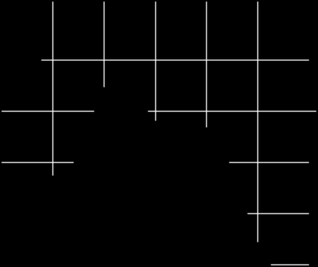
2 2 Spectroscopy P A Laser PMP λ/4 or λ/2 Figure : The experimental setup. P = polarizer; A = analyzer; λ, λ/4 or λ/2 = standard crystal plate; CP = investigated crystal plate; PMP =photomultiplier. CP.3.2. E P (d 2 d ) (μm) Figure 3: The dependence of the relative intensity of the difference between the thicknesses (d 2 d ) of the quartz plates for heliumneon laser radiation. z E oe E oe E oea α γ β E oea A First, the light beam transmitted through the polarizer is divided into two beams in the reference crystal plate with orthogonal polarizations (e and o). Then, the e and o rays also divide inside the investigated crystal plate (ee, eo, oe, andoo). The phase acquired by the beams at the output of the crystal will be φ ee = 2π λ (d +d 2 )n e, z 2 φ eo = 2π λ (d n e +d 2 n o ), φ oe = 2π λ (d n o +d 2 n e ), () Figure 2: The orientation of the optical axes of crystal plates in relation to the planes of polarizer and analyzer transmission. P = transmission plane of polarizer; A = transmission plane of analyzer; z,z 2 = optical axes of the first and second crystal plates, respectively; α=γ=45 ; β=9. 2. Methods Consideranopticalsystemconsistingofapolarizer,two crystal plates, and an analyzer (Figure ). The orientation of the optical axes of the crystal plates and a transmission planeofthepolarizerandtheanalyzerareshowninfigure 2. The direction of the reference angle is clockwise. Quartz crystals were chosen as the object of research because quartz isusuallyusedforthemanufactureofquarter-wave(halfwave) plates. The Gaussian profile has been used to model the intensity distribution of the cross-section of the light beam. φ oo = 2π λ (d +d 2 )n o, where d = standard thickness, d 2 =thicknessoftheinvestigated sample, and n o,n e = indicators of the ordinary and extraordinary rays, respectively. By projecting the electric field vectors of the light waves ee, eo, oe, and oo onto the transmission plane of the analyzer according to the law of cosines and taking into consideration the fact that I E 2, the following equation is formed: I=I [cos 2 α cos 2 β cos 2 γ+cos 2 α sin 2 β sin 2 γ + sin 2 α sin 2 β cos 2 γ+sin 2 α cos 2 β sin 2 γ cos 2α sin 2β sin 2γ cos ( 2π λ d 2Δn)
3 Spectroscopy λ ( 7 m) (a) λ ( 7 m) (b) λ ( 7 m) (c) λ ( 7 m) (d) Figure 4: (a) The transmission spectrum of the polarizer-crystal-crystal-analyzer system quartz crystals; d =d 2 = 2.27 mm; α=6 ; β= ; γ=9. (b) The transmission spectrum of the polarizer-crystal-crystal-analyzer system quartz crystals; d =d 2 = 2.27 mm; α=6 ; β= ; γ=3. (c) The transmission spectrum of the polarizer-crystal-crystal-analyzer system quartz crystals; d =d 2 = 2.27 mm; α=3 ; β=3 ; γ=3. (d) The transmission spectrum of the polarizer-crystal-crystal-analyzer system quartz crystals; d =d 2 = 2.27 mm; α=6 ; β= ; γ=6. sin 2α sin 2β cos 2γ cos ( 2π λ d Δn) sin 2α cos 2 β sin 2γ cos ( 2π λ (d +d 2 )Δn) + sin 2α sin 2 β sin 2γ cos ( 2π λ (d 2 d )Δn)], where I,I = the light intensity at the entrance and exit of the optical system, respectively, d = standard thickness, d 2 = thickness of the sample, and Δn = birefringence of the crystal. (2) 3. Results and Discussion At α=45, β=9,andγ= 45,wehaveonlyeo and oe beams with the respective phases (), and the expression (2) will be I=I [cos 2 α sin 2 β sin 2 γ+sin 2 α sin 2 β cos 2 γ +sin 2α sin 2 β sin 2γ cos ( 2π λ (d 2 d )Δn)]. (3)
4 4 Spectroscopy For α = 45, β = 9 and γ = 45,ifthedifferencein thickness between the standard and the test sample is (d 2 d )=± mλ, (m =,, 2, 3,...), (4) Δn the intensity at the output of the optical system is zero, which corresponds to the quarter-wave (half-wave) plate. For helium-neon laser radiation (λ = 3 micron) and the sample quartz plate (Δn =.9), the thickness difference (d 2 d ) must be a multiple of 7 microns. If the thickness difference between the standard and the test sample is different from condition (4), this sample does not correspond to the quarter-wave (half-wave) plate. Figure 3 shows the dependence of the relative intensity of the thickness difference (I/I )(d 2 d ) on quartz plates using helium-neon radiation. The form of the polarized spectrum of the transmission for the researched system is determined by the angles γ, β, andα (Figure 4). The spectrum s shape can be a line (Figure 4(b)), continuous (Figure 4(a))ormixed (Figures 4(c) and 4(d)). The frequency of the line spectrum is defined by the ratio of the angles α and β and the thickness ofthecrystalplates.thesmallertheeffectivethicknessofthe plates, the greater the spectral peaks, and vice versa. 4. Conclusion Theoretically it was found that using a polarizer-crystalcrystal-analyzer system where one of the crystals is the standard, it is possible, according to the intensity of the transmitted radiation, to control the compliance of the sample to a quarter-wave (half-wave) plate. For such control, two pairs of orthogonal transmission planes (polarizer-analyzer) and the main sections of crystalline plates (Figure 2)must be oriented at an angle of 45 (in this case, α = γ = 45, β = 9 ). Further, the spectrum at the output of the optical system is determined by the mutual orientation of the optical elements and the thickness of the crystal plates, which can be used to control a wide spectrum range. [4] A. F. Konstantinova, K. A. Rudoy, B. V. Nabatov, E. A. Evdishchenko, V. I. Stroganov, and O. Y. Pikul, The influence of optical activity on the intensity and polarization parameters of transmitted light in crystals, Crystallography Reports,vol.48, no.5,pp ,23. [5] O. Pikoul, Determination of the optical sign of a crystal by a conoscopic method, Applied Crystallography, vol. 43, no.5,pp ,2. [6] B. N. Grechushnikov, A. I. Vislobokov, E. A. Evdishchenko et al., Compound phase plates, Kristallografiya,vol.38,no.2,pp , 993. [7] B. N. Grechushnikov, A. I. Vislobokov, E. A. Evdishchenko et al., Compoundphase plates, Crystallography Reports, vol. 38, no. 2, pp. 64 7, 993. [8] H. K. Aben, Characteristic directions in optics of twisted birefringent media, JournaloftheOpticalSocietyofAmericaA, vol. 3, no. 9, pp , 986. [9]I.V.Gol tser,m.ya.darsht,b.ya.zel dovich,andn.d. Kundikova, Optically active analog of a quarter-wave plate, Quantum Electronics,vol.23,no.9,p.796,993. [] A. V. Vityazev, V. A. Demchenko, and V. V. Korotaev, How rotations of thin-film Polaroids affect the polarization state of radiation, Optical Technology, vol.65,no.,pp.32 34, 998. [] A. V. Syuǐ, N. A. Kravtsova, V. I. Stroganov, and V. V. Krishtop, Orientation dependence of the transmission of a polarizercrystal-crystal-analyzer system, Optical Technology, vol.74,no.7,pp ,27. [2] A. V. Syuy and V. I. Stroganov, Interference of conoscopic pictures of optical crystals, Optics Communications,vol.28,no. 24, pp , 28. [3] A. V. Syuy, N. A. Kravtsova, V. I. Stroganov, V. V. Lihtin, V. V. Krishtop, and V. A. Maksimenko, Peculiar properties of polarized transmission spectrums of crystal plates, in Laser Optics: Wavefront Transformation and Laser Beam Control, L. N.Soms,Ed.,vol.6639ofProceedings of SPIE,June26. Acknowledgment This work was supported by the Ministry of Education and Science of the Russian Federation (Federal Target Program Human Capital for Science and Education in Innovative Russia for 29 23, State Contract nos and ). References [] P.S.Lopatina,V.V.Krishtop,V.I.Stroganovetal., Electrooptical modulation of broadband light with Gaussian amplitude distribution over the spectrum, Optics and Spectroscopy, vol. 3,no.2,pp.94 96,22. [2] M. Born and E. Wolf, Principles of Optics: Electromagnetic Theory of Propagation, Interference and Diffraction of Light, Cambridge University Press, Cambridge, UK, 999. [3]W.A.Shurcliff,Polarized Light: Production and Use, Harvard University Press, Cambridge, Mass, USA, 966.


5 International Medicinal Chemistry Photoenergy International Organic Chemistry International International Analytical Chemistry Advances in Physical Chemistry International Carbohydrate Chemistry Quantum Chemistry Submit your manuscripts at The Scientific World Journal International Inorganic Chemistry Theoretical Chemistry Spectroscopy Analytical Methods in Chemistry Chromatography Research International International Electrochemistry Catalysts Applied Chemistry Bioinorganic Chemistry and Applications International Chemistry Spectroscopy
Chap. 5. Jones Calculus and Its Application to Birefringent Optical Systems
 Chap. 5. Jones Calculus and Its Application to Birefringent Optical Systems - The overall optical transmission through many optical components such as polarizers, EO modulators, filters, retardation plates.
ECE 185 ELECTRO-OPTIC MODULATION OF LIGHT
 ECE 185 ELECTRO-OPTIC MODULATION OF LIGHT I. Objective: To study the Pockels electro-optic (EO) effect, and the property of light propagation in anisotropic medium, especially polarization-rotation effects.
Polarization of Light and Birefringence of Materials
 Polarization of Light and Birefringence of Materials Ajit Balagopal (Team Members Karunanand Ogirala, Hui Shen) ECE 614- PHOTONIC INFORMATION PROCESSING LABORATORY Abstract-- In this project, we study
Chiroptical Spectroscopy
 Chiroptical Spectroscopy Theory and Applications in Organic Chemistry Lecture 2: Polarized light Masters Level Class (181 041) Mondays, 8.15-9.45 am, NC 02/99 Wednesdays, 10.15-11.45 am, NC 02/99 28 Electromagnetic
Lecture 5: Polarization. Polarized Light in the Universe. Descriptions of Polarized Light. Polarizers. Retarders. Outline
 Lecture 5: Polarization Outline 1 Polarized Light in the Universe 2 Descriptions of Polarized Light 3 Polarizers 4 Retarders Christoph U. Keller, Leiden University, keller@strw.leidenuniv.nl ATI 2016,
Light for which the orientation of the electric field is constant although its magnitude and sign vary in time.
 L e c t u r e 8 1 Polarization Polarized light Light for which the orientation of the electric field is constant although its magnitude and sign vary in time. Imagine two harmonic, linearly polarized light
4. Circular Dichroism - Spectroscopy
 4. Circular Dichroism - Spectroscopy The optical rotatory dispersion (ORD) and the circular dichroism (CD) are special variations of absorption spectroscopy in the UV and VIS region of the spectrum. The
INVESTIGATION OF MANIFESTATION OF OPTICAL ACTIVITY IN ANISOTROPIC CRYSTALS. Moscow, Russia,
 INVESTIGATION OF MANIFESTATION OF OPTICAL ACTIVITY IN ANISOTROPIC CRYSTALS A.F. Konstantinova 1, E.A. Evdishchenko 1, K.A. Kaldybaev, K.B. Imangazieva, K.K. Konstantinov 1 1 Shubnikov Institute of Crystallography,
Brewster Angle and Total Internal Reflection
 Lecture 4: Polarization Outline 1 Polarized Light in the Universe 2 Brewster Angle and Total Internal Reflection 3 Descriptions of Polarized Light 4 Polarizers 5 Retarders Christoph U. Keller, Utrecht
Research Article Trapped-Mode Resonance Regime of Thin Microwave Electromagnetic Arrays with Two Concentric Rings in Unit Cell
 Microwave Science and Technology Volume 2, Article ID 3688, 6 pages doi:.55/2/3688 Research Article Trapped-Mode Resonance Regime of Thin Microwave Electromagnetic Arrays with Two Concentric Rings in Unit
Channel Optical Waveguides with Spatial Longitudinal Modulation of Their Parameters Induced in Photorefractive Lithium Niobate Samples
 Russian Forum of Young Scientists Volume 2018 Conference Paper Channel Optical Waveguides with Spatial Longitudinal Modulation of Their Parameters Induced in Photorefractive Lithium Niobate Samples A D
September 14, Monday 4. Tools for Solar Observations-II
 September 14, Monday 4. Tools for Solar Observations-II Spectrographs. Measurements of the line shift. Spectrograph Most solar spectrographs use reflection gratings. a(sinα+sinβ) grating constant Blazed
Physics I Keystone Institute Technology & Management Unit-II
 Un-polarized light Ordinary light is a collection of wave trains emitted by atoms or group of atoms with coherent time no longer than 10-8 second. Each wave train has different orientation and phase of
Brewster Angle and Total Internal Reflection
 Lecture 5: Polarization Outline 1 Polarized Light in the Universe 2 Brewster Angle and Total Internal Reflection 3 Descriptions of Polarized Light 4 Polarizers 5 Retarders Christoph U. Keller, Leiden University,
polarisation of Light
 Basic concepts to understand polarisation of Light Polarization of Light Nature of light: light waves are transverse in nature i. e. the waves propagates in a direction perpendicular to the direction of
Lab #13: Polarization
 Lab #13: Polarization Introduction In this experiment we will investigate various properties associated with polarized light. We will study both its generation and application. Real world applications
Lecture 3 : Electrooptic effect, optical activity and basics of interference colors with wave plates
 Lecture 3 : Electrooptic effect, optical activity and basics of interference colors with wave plates NW optique physique II 1 Electrooptic effect Electrooptic effect: example of a KDP Pockels cell Liquid
POLARIZATION OF LIGHT
 POLARIZATION OF LIGHT OVERALL GOALS The Polarization of Light lab strongly emphasizes connecting mathematical formalism with measurable results. It is not your job to understand every aspect of the theory,
Research Article Band Structure Engineering in 2D Photonic Crystal Waveguide with Rhombic Cross-Section Elements
 Advances in Optical Technologies Volume 214, Article ID 78142, 5 pages http://dx.doi.org/1155/214/78142 Research Article Band Structure Engineering in 2D Photonic Crystal Waveguide with Rhombic Cross-Section
Phys 531 Lecture 27 6 December 2005
 Phys 531 Lecture 27 6 December 2005 Final Review Last time: introduction to quantum field theory Like QM, but field is quantum variable rather than x, p for particle Understand photons, noise, weird quantum
Application of Small-Angular Magnetooptic Polarimetry for Study of Magnetogyration in (Ga 0.3 In 0.7 ) 2 Se 3 and SiO 2 Crystals
 2 Se 3 and SiO 2 Crystals") Application of Small-Angular Magnetooptic Polarimetry for Study of Magnetogyration in (Ga.3 In.7 ) 2 Se 3 and SiO 2 Crystals O. Krupych, Yu. Vasyliv, D. Adameno, R. Vloh and O. Vloh Institute of Physical
Application of Small-Angular Magnetooptic Polarimetry for Study of Magnetogyration in (Ga.3 In.7 ) 2 Se 3 and SiO 2 Crystals O. Krupych, Yu. Vasyliv, D. Adameno, R. Vloh and O. Vloh Institute of Physical
[D] indicates a Design Question
![[D] indicates a Design Question](/thumbs/77/76276479.jpg "[D] indicates a Design Question") EP421 Assignment 4: Polarization II: Applications of Optical Anisotropy use of the Jones Calculus (Handed Out: Friday 1 November 2013 Due Back: Friday 8 November 2013) 1. Optic Axis of Birefringent Crystals
EP421 Assignment 4: Polarization II: Applications of Optical Anisotropy use of the Jones Calculus (Handed Out: Friday 1 November 2013 Due Back: Friday 8 November 2013) 1. Optic Axis of Birefringent Crystals
Optics and Optical Design. Chapter 6: Polarization Optics. Lectures 11 13
 Optics and Optical Design Chapter 6: Polarization Optics Lectures 11 13 Cord Arnold / Anne L Huillier Polarization of Light Arbitrary wave vs. paraxial wave One component in x direction y x z Components
Polarized Light. Nikki Truss. Abstract:
 Polarized Light Nikki Truss 9369481 Abstract: In this experiment, the properties of linearly polarised light were examined. Malus Law was verified using the apparatus shown in Fig. 1. Reflectance of s-polarised
POLARIZATION FUNDAMENTAL OPTICS POLARIZATION STATES 1. CARTESIAN REPRESENTATION 2. CIRCULAR REPRESENTATION. Polarization. marketplace.idexop.
 POLARIZATION POLARIZATION STATS Four numbers are required to describe a single plane wave Fourier component traveling in the + z direction. These can be thought of as the amplitude and phase shift of the
POLARISATION. We have not really discussed the direction of the Electric field other that that it is perpendicular to the direction of motion.
 POLARISATION Light is a transverse electromagnetic wave. We have not really discussed the direction of the Electric field other that that it is perpendicular to the direction of motion. If the E field
Testing stress birefringence of an optical window. Chiayu Ai and. James C. Wyant. WYKO Corp., 2650 E. Elvira Road, Tucson, AZ ABSTRACT
 Testing stress birefringence of an optical window Chiayu Ai and James C. Wyant WYKO Corp., 2650 E. Elvira Road, Tucson, AZ 85706 ABSTRACT This paper describes a method to measure the birefringence of an
Waveplate analyzer using binary magneto-optic rotators
 Waveplate analyzer using binary magneto-optic rotators Xiaojun Chen 1, Lianshan Yan 1, and X. Steve Yao 1, 1. General Photonics Corp. Chino, CA, 91710, USA Tel: 909-590-5473 Fax: 909-90-5535. Polarization
Optics and Optical Design. Chapter 6: Polarization Optics. Lectures 11-13
 Optics and Optical Design Chapter 6: Polarization Optics Lectures 11-13 Cord Arnold / Anne L Huillier Polarization of Light Arbitrary wave vs. paraxial wave One component in x-direction y x z Components
Polarization degree fading during propagation of partially coherent light through retarders
 OPTO-ELECTRONICS REVIEW 3(), 7 76 7 th International Workshop on Nonlinear Optics Applications Polarization degree fading during propagation of partially coherent light through retarders A.W. DOMAÑSKI
16. More About Polarization
 16. More About Polarization Polarization control Wave plates Circular polarizers Reflection & polarization Scattering & polarization Birefringent materials have more than one refractive index A special
Research Article Noncontact Measurement for Radius of Curvature of Unpolished Lens
 International Optics, Article ID 3403, 7 pages http://dx.doi.org/10.1155/014/3403 Research Article Noncontact Measurement for Radius of Curvature of Unpolished Lens Haifeng Liang College of Photoelectrical
Chapter 2 Basic Optics
 Chapter Basic Optics.1 Introduction In this chapter we will discuss the basic concepts associated with polarization, diffraction, and interference of a light wave. The concepts developed in this chapter
Wave Propagation in Uniaxial Media. Reflection and Transmission at Interfaces
 Lecture 5: Crystal Optics Outline 1 Homogeneous, Anisotropic Media 2 Crystals 3 Plane Waves in Anisotropic Media 4 Wave Propagation in Uniaxial Media 5 Reflection and Transmission at Interfaces Christoph
Research Article Dual-Domain Transform for Travelling Wave in FRFT Domain
 International Scholarly Research Network ISRN Applied Mathematics Volume 011, Article ID 161643, 8 pages doi:10.540/011/161643 Research Article Dual-Domain Transform for Travelling Wave in FRFT Domain
Polarimetry in the E-ELT era. Polarized Light in the Universe. Descriptions of Polarized Light. Polarizers. Retarders. Fundamentals of Polarized Light
 Polarimetry in the E-ELT era Fundamentals of Polarized Light 1 Polarized Light in the Universe 2 Descriptions of Polarized Light 3 Polarizers 4 Retarders Christoph U. Keller, Leiden University, keller@strw.leidenuniv.nl
Research Article Elementary Statistical Models for Vector Collision-Sequence Interference Effects with Poisson-Distributed Collision Times
 Spectroscopy Volume, Article ID 56697, 5 pages doi:55//56697 Research Article Elementary Statistical Models for Vector Collision-Sequence Interference Effects with Poisson-Distributed Collision Times John
NAWAB SHAH ALAM KHAN COLLEGE OF ENGINEERING & TECHNOLOGY UNIT II-a POLARISATION
 NAWAB SHAH ALAM KHAN COLLEGE OF ENGINEERING & TECHNOLOGY UNIT II-a 1 POLARISATION SYLLABUS :Polarization: Introduction, Malus s law, double refraction, Nicol prism, Quarter wave and half wave plates. 1.
Birefringence dispersion in a quartz crystal retrieved from a channelled spectrum resolved by a fibre-optic spectrometer
 Birefringence dispersion in a quartz crystal retrieved from a channelled spectrum resolved by a fibre-optic spectrometer Petr Hlubina, Dalibor Ciprian Department of Physics, Technical University Ostrava,
Lecture 4: Polarisation of light, introduction
 Lecture 4: Polarisation of light, introduction Lecture aims to explain: 1. Light as a transverse electro-magnetic wave 2. Importance of polarisation of light 3. Linearly polarised light 4. Natural light
Experiment 8. Fresnel Coefficients. 8.1 Introduction. References
 Experiment 8 Fresnel Coefficients References Optics by Eugene Hecht, Chapter 4 Introduction to Modern Optics by Grant Fowles, Chapter 2 Principles of Optics by Max Born and Emil Wolf, Chapter 1 Optical
PMARIZED LI6HT FUNDAMENTALS AND APPLICATIONS EBWABD COLLETT. Measurement Concepts, Inc. Colts Neck, New Jersey
 PMARIZED LI6HT FUNDAMENTALS AND APPLICATIONS EBWABD COLLETT Measurement Concepts, Inc. Colts Neck, New Jersey Marcel Dekker, Inc. New York Basel Hong Kong About the Series Preface A Historical Note iii
Physics of Light and Optics
 Physics of Light and Optics Justin Peatross and Harold Stokes Brigham Young University Department of Physics and Astronomy All Publication Rights Reserved (2001) Revised April 2002 This project is supported
Polarizers and Retarders
 Phys 531 Lecture 20 11 November 2004 Polarizers and Retarders Last time, discussed basics of polarization Linear, circular, elliptical states Describe by polarization vector ĵ Today: Describe elements
Polarized Light. Second Edition, Revised and Expanded. Dennis Goldstein Air Force Research Laboratory Eglin Air Force Base, Florida, U.S.A.
 Polarized Light Second Edition, Revised and Expanded Dennis Goldstein Air Force Research Laboratory Eglin Air Force Base, Florida, U.S.A. ш DEK KER MARCEL DEKKER, INC. NEW YORK BASEL Contents Preface to
Research Article Dispersion of Love Waves in a Composite Layer Resting on Monoclinic Half-Space
 Applied Mathematics Volume 011, Article ID 71349, 9 pages doi:10.1155/011/71349 Research Article Dispersion of Love Waves in a Composite Layer Resting on Monoclinic Half-Space Sukumar Saha BAS Division,
Research Article Study of Transport Properties of Tris (hydroxymethyl)aminomethane Hydrochloride in 20% (v/v) Acetone-Water System at 303.
aminomethane Hydrochloride in 20% (v/v) Acetone-Water System at 303.") Applied Chemistry Volume 03, Article ID 8053, 4 pages http://dx.doi.org/0.55/03/8053 Research Article Study of Transport Properties of Tris (hydroxymethyl)aminomethane Hydrochloride in 0% (v/v) Acetone-Water
Applied Chemistry Volume 03, Article ID 8053, 4 pages http://dx.doi.org/0.55/03/8053 Research Article Study of Transport Properties of Tris (hydroxymethyl)aminomethane Hydrochloride in 0% (v/v) Acetone-Water
Research Article Analysis of Power Loss for Crystalline Silicon Solar Module during the Course of Encapsulation
 International Photoenergy Volume 2015, Article ID 251615, 5 pages http://dx.doi.org/10.1155/2015/251615 Research Article Analysis of Power Loss for Crystalline Silicon Solar Module during the Course of
Physics 221A Fall 2005 Homework 8 Due Thursday, October 27, 2005
 Physics 22A Fall 2005 Homework 8 Due Thursday, October 27, 2005 Reading Assignment: Sakurai pp. 56 74, 87 95, Notes 0, Notes.. The axis ˆn of a rotation R is a vector that is left invariant by the action
Modeling of the propagation of Bessel beams in a uniaxial crystal at different positions of the crystal axis
 Modeling of the propagation of Bessel beams in a uniaxial crystal at different positions of the crystal axis Krasnov A.P. Samara State Aerospace University Abstract. The numerical study of the propagation
Topic 4: Waves 4.3 Wave characteristics
 Guidance: Students will be expected to calculate the resultant of two waves or pulses both graphically and algebraically Methods of polarization will be restricted to the use of polarizing filters and
: Imaging Systems Laboratory II. Laboratory 6: The Polarization of Light April 16 & 18, 2002
 151-232: Imaging Systems Laboratory II Laboratory 6: The Polarization of Light April 16 & 18, 22 Abstract. In this lab, we will investigate linear and circular polarization of light. Linearly polarized
Chap. 2. Polarization of Optical Waves
 Chap. 2. Polarization of Optical Waves 2.1 Polarization States - Direction of the Electric Field Vector : r E = E xˆ + E yˆ E x x y ( ω t kz + ϕ ), E = E ( ωt kz + ϕ ) = E cos 0 x cos x y 0 y - Role :
Deviations from Malus Law
 From: Steve Scott, Jinseok Ko, Howard Yuh To: MSE Enthusiasts Re: MSE Memo #18a: Linear Polarizers and Flat Glass Plates Date: January 16, 2004 This memo discusses three issues: 1. When we measure the
OPSE FINAL EXAM Fall 2016 YOU MUST SHOW YOUR WORK. ANSWERS THAT ARE NOT JUSTIFIED WILL BE GIVEN ZERO CREDIT.
 CLOSED BOOK. Equation Sheet is provided. YOU MUST SHOW YOUR WORK. ANSWERS THAT ARE NOT JUSTIFIED WILL BE GIVEN ZERO CREDIT. ALL NUMERICAL ANSERS MUST HAVE UNITS INDICATED. (Except dimensionless units like
Research Article Analytical Approach to Polarization Mode Dispersion in Linearly Spun Fiber with Birefringence
 International Optics Volume 216, Article ID 9753151, 9 pages http://dx.doi.org/1.1155/216/9753151 Research Article Analytical Approach to Polarization Mode Dispersion in Linearly Spun Fiber with Birefringence
4: birefringence and phase matching
 /3/7 4: birefringence and phase matching Polarization states in EM Linear anisotropic response χ () tensor and its symmetry properties Working with the index ellipsoid: angle tuning Phase matching in crystals
Chapter 9 - Polarization
 Chapter 9 - Polarization Gabriel Popescu University of Illinois at Urbana Champaign Beckman Institute Quantitative Light Imaging Laboratory http://light.ece.uiuc.edu Principles of Optical Imaging Electrical
Optics. n n. sin c. sin
 Optics Geometrical optics (model) Light-ray: extremely thin parallel light beam Using this model, the explanation of several optical phenomena can be given as the solution of simple geometric problems.
Lecture 8: Polarimetry 2. Polarizers and Retarders. Polarimeters. Scattering Polarization. Zeeman Effect. Outline
 Lecture 8: Polarimetry 2 Outline 1 Polarizers and Retarders 2 Polarimeters 3 Scattering Polarization 4 Zeeman Effect Christoph U. Keller, Utrecht University, C.U.Keller@uu.nl Observational Astrophysics
Research Article Wave Scattering in Inhomogeneous Strings
 International Scholarly Research Network ISRN Mathematical Analysis Volume 011, Article ID 64049, 14 pages doi:10.540/011/64049 Research Article Wave Scattering in Inhomogeneous Strings Nezam Iraniparast
Spectroscopic Measurements of Optical Elements For Submillimeter Receivers
 5- Abstract Spectroscopic Measurements of Optical Elements For Submillimeter Receivers J. Kawamura, S. Paine, and D. C. Papa Harvard-Smithsonian Center for Astrophysics 60 Garden Street Cambridge, Massachusetts
Modeling of the fringe shift in multiple beam interference for glass fibers
 PRAMANA c Indian Academy of Sciences Vol. 70, No. 4 journal of April 2008 physics pp. 643 648 Modeling of the fringe shift in multiple beam interference for glass fibers A M HAMED 1 Physics Department,
Polarization. Polarization. Physics Waves & Oscillations 4/3/2016. Spring 2016 Semester Matthew Jones. Two problems to be considered today:
 4/3/26 Physics 422 Waves & Oscillations Lecture 34 Polarization of Light Spring 26 Semester Matthew Jones Polarization (,)= cos (,)= cos + Unpolarizedlight: Random,, Linear polarization: =,± Circular polarization:
Research Article Soliton Solutions for the Wick-Type Stochastic KP Equation
 Abstract and Applied Analysis Volume 212, Article ID 327682, 9 pages doi:1.1155/212/327682 Research Article Soliton Solutions for the Wick-Type Stochastic KP Equation Y. F. Guo, 1, 2 L. M. Ling, 2 and
Complex refractive-index measurement based on Fresnel s equations and the uses of heterodyne interferometry
 Complex refractive-index measurement based on Fresnel s equations and the uses of heterodyne interferometry Ming-Horng Chiu, Ju-Yi Lee, and Der-Chin Su The phase difference between s and p polarization
PHY410 Optics Exam #3
 PHY410 Optics Exam #3 NAME: 1 2 Multiple Choice Section - 5 pts each 1. A continuous He-Ne laser beam (632.8 nm) is chopped, using a spinning aperture, into 500 nanosecond pulses. Compute the resultant
Phys 2310 Mon. Oct. 30, 2017 Today s Topics. Begin Modern Optics Ch. 2: The Nature of Polarized Light Reading for Next Time
 Phys 3 Mon. Oct. 3, 7 Today s Topics Begin Modern Optics Ch. : The Nature of Polarized Light Reading for Next Time By Wed.: Reading this Week Begin Ch. of Modern Optics (. 8.) Nature of Polarized Light,
Optical Mineralogy. Optical Mineralogy. Use of the petrographic microscope
 Optical Mineralogy Optical Mineralogy Use of the petrographic microscope John Winter, Whitman College with some slides Jane Selverstone, University of New Mexico, 2003 Why use the microscope?? Identify
OPTI 511L Fall A. Demonstrate frequency doubling of a YAG laser (1064 nm -> 532 nm).
.") R.J. Jones Optical Sciences OPTI 511L Fall 2017 Experiment 3: Second Harmonic Generation (SHG) (1 week lab) In this experiment we produce 0.53 µm (green) light by frequency doubling of a 1.06 µm (infrared)
R.J. Jones Optical Sciences OPTI 511L Fall 2017 Experiment 3: Second Harmonic Generation (SHG) (1 week lab) In this experiment we produce 0.53 µm (green) light by frequency doubling of a 1.06 µm (infrared)
Polarization Mode Dispersion
 Unit-7: Polarization Mode Dispersion https://sites.google.com/a/faculty.muet.edu.pk/abdullatif Department of Telecommunication, MUET UET Jamshoro 1 Goos Hänchen Shift The Goos-Hänchen effect is a phenomenon
The science of light. P. Ewart
 The science of light P. Ewart Oxford Physics: Second Year, Optics Parallel reflecting surfaces t images source Extended source path difference xcos 2t=x Fringes localized at infinity Circular fringe constant
OPTICAL PROPERTIES OF THE DIRC FUSED SILICA CHERENKOV RADIATOR
 OPTICAL PROPERTIES OF THE DIRC FUSED SILICA CHERENKOV RADIATOR J. Cohen-Tanugi, M. Convery, B. Ratcliff, X. Sarazin, J. Schwiening, and J. Va'vra * Stanford Linear Accelerator Center, Stanford University,
Supporting Information
 Supporting Information Devlin et al. 10.1073/pnas.1611740113 Optical Characterization We deposit blanket TiO films via ALD onto silicon substrates to prepare samples for spectroscopic ellipsometry (SE)
OPTICS LAB -ECEN 5606
 Department of Electrical and Computer Engineering University of Colorado at Boulder OPTICS LAB -ECEN 5606 Kelvin Wagner KW&K.Y. Wu 1994 KW&S.Kim 2007 Experiment No. 12 POLARIZATION and CRYSTAL OPTICS 1
Chap. 4. Electromagnetic Propagation in Anisotropic Media
 Chap. 4. Electromagnetic Propagation in Anisotropic Media - Optical properties depend on the direction of propagation and the polarization of the light. - Crystals such as calcite, quartz, KDP, and liquid
Quarter wave plates and Jones calculus for optical system
 2/11/16 Electromagnetic Processes In Dispersive Media, Lecture 6 1 Quarter wave plates and Jones calculus for optical system T. Johnson 2/11/16 Electromagnetic Processes In Dispersive Media, Lecture 6
50%-50% Beam Splitters Using Transparent Substrates Coated by Single- or Double-Layer Quarter-Wave Thin Films
 University of New Orleans ScholarWorks@UNO University of New Orleans Theses and Dissertations Dissertations and Theses 5-22-2006 50%-50% Beam Splitters Using Transparent Substrates Coated by Single- or
14. Matrix treatment of polarization
 14. Matri treatment of polarization This lecture Polarized Light : linear, circular, elliptical Jones Vectors for Polarized Light Jones Matrices for Polarizers, Phase Retarders, Rotators (Linear) Polarization
1. Consider the biconvex thick lens shown in the figure below, made from transparent material with index n and thickness L.
 Optical Science and Engineering 2013 Advanced Optics Exam Answer all questions. Begin each question on a new blank page. Put your banner ID at the top of each page. Please staple all pages for each individual
JRE Group of Institutions ASSIGNMENT # 1 Special Theory of Relativity
 ASSIGNMENT # 1 Special Theory of Relativity 1. What was the objective of conducting the Michelson-Morley experiment? Describe the experiment. How is the negative result of the experiment interpreted? 2.
OPSE FINAL EXAM Fall 2015 YOU MUST SHOW YOUR WORK. ANSWERS THAT ARE NOT JUSTIFIED WILL BE GIVEN ZERO CREDIT.
 CLOSED BOOK. Equation Sheet is provided. YOU MUST SHOW YOUR WORK. ANSWERS THAT ARE NOT JUSTIFIED WILL BE GIVEN ZERO CREDIT. ALL NUMERICAL ANSERS MUST HAVE UNITS INDICATED. (Except dimensionless units like
Optics, Light and Lasers
 Dieter Meschede Optics, Light and Lasers The Practical Approach to Modern Aspects of Photonics and Laser Physics Second, Revised and Enlarged Edition BICENTENNIAL.... n 4 '':- t' 1 8 0 7 $W1LEY 2007 tri
Lecture 9: Introduction to Diffraction of Light
 Lecture 9: Introduction to Diffraction of Light Lecture aims to explain: 1. Diffraction of waves in everyday life and applications 2. Interference of two one dimensional electromagnetic waves 3. Typical
Optical Systems Program of Studies Version 1.0 April 2012
 Optical Systems Program of Studies Version 1.0 April 2012 Standard1 Essential Understand Optical experimental methodology, data analysis, interpretation, and presentation strategies Essential Understandings:
PHYSICAL OPTICS. Ans: 1 Sol: The condition to form bright band at a point is to have a path difference of x = nλ From the given problem
 PHYSCAL OPTCS PREVOUS EAMCET BTS (ENGNEERNG PAPER). n the Young s doule slit experiment the intensities at two points P and P on the screen are respectively and. f P is located at the centre of right fringe
B.Tech. First Semester Examination Physics-1 (PHY-101F)
") B.Tech. First Semester Examination Physics-1 (PHY-101F) Note : Attempt FIVE questions in all taking least two questions from each Part. All questions carry equal marks Part-A Q. 1. (a) What are Newton's
B.Tech. First Semester Examination Physics-1 (PHY-101F) Note : Attempt FIVE questions in all taking least two questions from each Part. All questions carry equal marks Part-A Q. 1. (a) What are Newton's
Research Article Translative Packing of Unit Squares into Squares
 International Mathematics and Mathematical Sciences Volume 01, Article ID 61301, 7 pages doi:10.1155/01/61301 Research Article Translative Packing of Unit Squares into Squares Janusz Januszewski Institute
Preview from Notesale.co.uk Page 1 of 38
 F UNDAMENTALS OF PHOTONICS Module 1.1 Nature and Properties of Light Linda J. Vandergriff Director of Photonics System Engineering Science Applications International Corporation McLean, Virginia Light
Introduction to Polarization
 Phone: Ext 659, E-mail: hcchui@mail.ncku.edu.tw Fall/007 Introduction to Polarization Text Book: A Yariv and P Yeh, Photonics, Oxford (007) 1.6 Polarization States and Representations (Stokes Parameters
MP5: Soft Matter: Physics of Liquid Crystals
 MP5: Soft Matter: Physics of Liquid Crystals 1 Objective In this experiment a liquid crystal display (LCD) is built and its functionality is tested. The light transmission as function of the applied voltage
Physical Optics 2018 Dr. Muwafaq Fadhil Al-Mishlab Third lecture [ Huygens Principle, Interference of light]
![Physical Optics 2018 Dr. Muwafaq Fadhil Al-Mishlab Third lecture [ Huygens Principle, Interference of light]](/thumbs/96/128206880.jpg "Physical Optics 2018 Dr. Muwafaq Fadhil Al-Mishlab Third lecture [ Huygens Principle, Interference of light]") Physical Optics 2018 Dr. Muwafaq Fadhil Al-Mishlab Third lecture [ Huygens Principle, Interference of light] 1. Huygens principle Long before people understood the electromagnetic character of light, Christian
Physical Optics 2018 Dr. Muwafaq Fadhil Al-Mishlab Third lecture [ Huygens Principle, Interference of light] 1. Huygens principle Long before people understood the electromagnetic character of light, Christian
Citation for published version (APA): Shen, C. (2006). Wave Propagation through Photonic Crystal Slabs: Imaging and Localization. [S.l.]: s.n.
![Citation for published version (APA): Shen, C. (2006). Wave Propagation through Photonic Crystal Slabs: Imaging and Localization. [S.l.]: s.n.](/thumbs/95/124821981.jpg "Citation for published version (APA): Shen, C. (2006). Wave Propagation through Photonic Crystal Slabs: Imaging and Localization. [S.l.]: s.n.") University of Groningen Wave Propagation through Photonic Crystal Slabs Shen, Chuanjian IMPORTANT NOTE: You are advised to consult the publisher's version (publisher's PDF) if you wish to cite from it.
University of Groningen Wave Propagation through Photonic Crystal Slabs Shen, Chuanjian IMPORTANT NOTE: You are advised to consult the publisher's version (publisher's PDF) if you wish to cite from it.
Modulators. Tuesday, 11/14/2006 Physics 158 Peter Beyersdorf. Document info 17. 1
 Modulators Tuesday, 11/14/2006 Physics 158 Peter Beyersdorf Document info 17. 1 Class Outline Birefringence Optical Activity Faraday Rotation Optical Modulators Electrooptic Modulators Accoustooptic Modulators
Lecture 0. NC State University
 Chemistry 736 Lecture 0 Overview NC State University Overview of Spectroscopy Electronic states and energies Transitions between states Absorption and emission Electronic spectroscopy Instrumentation Concepts
Chapter 4: Polarization of light
 Chapter 4: Polarization of light 1 Preliminaries and definitions B E Plane-wave approximation: E(r,t) ) and B(r,t) are uniform in the plane ^ k We will say that light polarization vector is along E(r,t)
Summary of Fourier Optics
 Summary of Fourier Optics Diffraction of the paraxial wave is described by Fresnel diffraction integral, u(x, y, z) = j λz dx 0 dy 0 u 0 (x 0, y 0 )e j(k/2z)[(x x 0) 2 +(y y 0 ) 2 )], Fraunhofer diffraction
Chapter 35 Diffraction and Polarization. Copyright 2009 Pearson Education, Inc.
 Chapter 35 Diffraction and Polarization 35-1 Diffraction by a Single Slit or Disk If light is a wave, it will diffract around a single slit or obstacle. 35-1 Diffraction by a Single Slit or Disk The resulting
Polarization division multiplexing system quality in the presence of polarization effects
 Opt Quant Electron (2009) 41:997 1006 DOI 10.1007/s11082-010-9412-0 Polarization division multiplexing system quality in the presence of polarization effects Krzysztof Perlicki Received: 6 January 2010
Research Article Two Mathematical Models for Generation of Crowned Tooth Surface
 e Scientific World Journal, Article ID 6409, 6 pages http://dx.doi.org/0.55/204/6409 Research Article Two Mathematical Models for Generation of Crowned Tooth Surface Laszlo Kelemen and Jozsef Szente University