Physics 294H. lectures will be posted frequently, mostly! every day if I can remember to do so
|
|
|
- Job Harrison
- 6 years ago
- Views:
Transcription
1 Physics 294H l Professor: Joey Huston l huston@msu.edu l office: BPS3230 l Homework will be with Mastering Physics (and an average of 1 hand-written problem per week) Help-room hours: 12:40-2:40 Monday (note change); 3:00-4:00 PM Friday hand-in problem for Wed Mar. 23: Note I revised Homework assignment 9 (due 3/23) adding some problems that were due a week later l Quizzes by iclicker (sometimes hand-written) l 2 nd exam next Thursday l Final exam Thursday May 5 10:00 AM 12:00 PM 1420 BPS l Course website: lectures will be posted frequently, mostly every day if I can remember to do so


2 l the plane containing the electric field vector and the Poynting vector S is called the plane of polarization of the EM wave Polarization

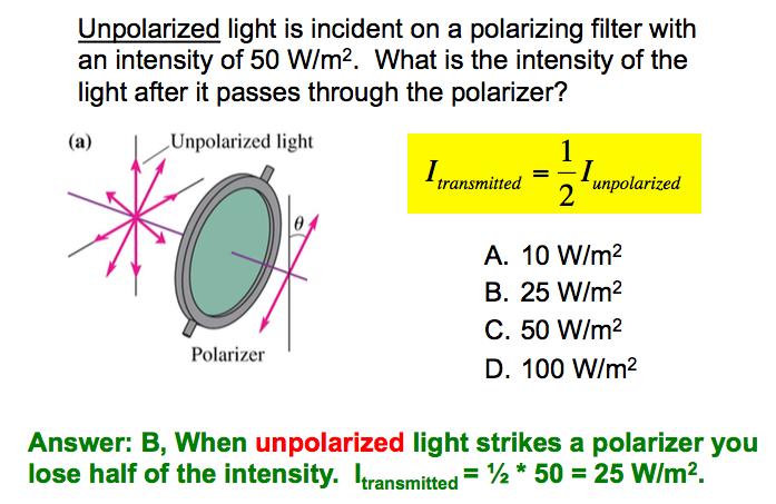
3 Polarizing filter l Ordinary electromagnetic waves are unpolarized the electric field vectors for each wave are random l A polarizing filter lets in only those EM waves with a polarization in a particular direction polymer chains are treated to make them conducting electrons absorb energy from EM waves whose electric fields oscillate in the direction of the chains

4 Polarization l Electric field from EM wave can be decomposed into components along x (perpendicular to polarization axis) and y directions (parallel to) E incident = E o sinθ ^ i + E o cosθ j ^ l If the filter is 100% efficient, then only component perpendicular to polarization axis is transmitted E transmitted = E o cosθ j l The intensity of light depends on the square of the electric field so for initial polarized light I transmitted = I o cos 2 θ (Malus law) ^
5 l If the light is initially unpolarized, then the direction of the electric field is random, and the average value of cos 2 θ is 0.5 I transmitted = I o cos 2 θ 1$ I transmitted = I o " # 2% & Polarization
6 iclicker question
7

8 l We saw earlier that an electric generator produced an alternating voltage and current AC circuits
9 l It is useful to represent AC voltages and currents with phasers Phasers
10 l It is useful to represent AC voltages and currents with phasers Phasers
11 Phasors l Wrong spelling sorry l A phasor is a vector that rotates counterclockwise around the origin with an angular frequency ω the instantaneous vaue of a quantity (voltage, current) is the projection of the phasor on the horizontal axis sometimes it s defined with respect to the vertical axis, but that just causes a phase change ωt is called the phase angle
12 AC circuits with resistors l Suppose I have a circuit consisting of an AC generator and a resistor l I want to look at the currents and voltages in the circuits l I do it the same way I did it for DC circuits, using Kirchoff s laws ΔV = ΔV source + ΔV R = ε v R = 0 v R = ε = ε cosωt l The voltage of the generator appears across the resistor, in phase
13 AC circuits with resistors l So I can write the voltage and current as instantaneous values v R = V R cosωt i R = v R R = V cosωt R R maximum values = I R cosωt l Note that the voltage and current are in phase with each other and they have the same angular velocity ω
14 AC circuits with capacitors l We can write the voltage across the capacitor as v c = V c cosωt ε o l The charge on the capacitor is q = Cv c = CV c cosωt l The current is i = dq dt = ωcv c sinωt
15 AC circuits with resistors l So I can write the voltage and current as instantaneous values v R = V R cosωt i R = v R R = V cosωt R R maximum values = I R cosωt l Note that the voltage and current are in phase with each other and they have the same angular velocity ω
16 AC circuits with capacitors l We can write the voltage across the capacitor as v c = V c cosωt ε o l The charge on the capacitor is q = Cv c = CV c cosωt l The current is i = dq dt = ωcv c sinωt
17 AC circuits with capacitors l I can also write # i = ωcv c cos ωt + π & $ % 2 ' ( l The AC current through a capacitor leads the voltage by 90 o
18 AC circuits with capacitors l We can define the capacitive reactance X c as X c = 1 ωc I c = V c X c V c = I c X c l Note that the reactance relates the peak voltage and the peak current and not the instantaneous voltage and current v c i c X c l The unit of reactance is Ω
19 iclicker question

20 iclicker question
21 Circuits with resistors and capacitors l If the frequency is low, then we expect X C to be larger than R, while if the frequency is high we expect X C to be smaller than R l For the phasor for this circuit, I and V R are in phase, V C is 90 o behind I l v R +v C =ε (at any point in time), so draw the emf phasor as the vector sum of V R and V C ε=ε o cosωt ε o 2 = V R 2 + V C 2 peak values
22 Circuits with resistors and capacitors l Calculate the current ε o 2 = V R 2 + V C 2 = (IR) 2 + (IX C ) 2 = (R 2 + X C 2 )I 2 # 1 = R 2 & + $ % ω 2 C 2 ' ( I 2 l Thus, I can write the peak current as ε I = o R 2 + X = ε o 2 C 1 R 2 + ω 2 C 2 l The peak voltages are ε V R = IR = o R R 2 + X = ε o R 2 C 1 R 2 + ω 2 C 2 ε o 2 = V R 2 + V C 2 V C = IX C = ε o X C R 2 + X = ε o X C 2 C 1 R 2 + ω 2 C 2
23 iclicker Does V R + V C = 0? A. Yes. B. No. C. Can t tell without knowing ω.
24 iclicker Does V R + V C = 0? A. Yes. B. No. C. Can t tell without knowing ωout knowing ω. Instantaneous voltages add. Peak voltages don t because the voltages are not in phase.
25 Filters l A low pass filter transmits a signal with a low frequency but blocks a signal with a high frequency l And vice versa for a high pass filter
12:40-2:40 3:00-4:00 PM
 PHY294H l Professor: Joey Huston l email:huston@msu.edu l office: BPS3230 l Homework will be with Mastering Physics (and an average of 1 handwritten problem per week) Help-room hours: 12:40-2:40 Monday
MP ) 12:40-2:40 3:00-4:00 PM
 12:40-2:40 3:00-4:00 PM") PHY294H l Professor: Joey Huston l email:huston@msu.edu l office: BPS3230 l Homework will be with Mastering Physics (and an average of 1 handwritten problem per week) Problem 29.77 (already assigned) will
PHY294H l Professor: Joey Huston l email:huston@msu.edu l office: BPS3230 l Homework will be with Mastering Physics (and an average of 1 handwritten problem per week) Problem 29.77 (already assigned) will
Course Updates. Reminders: 1) Assignment #10 due Today. 2) Quiz # 5 Friday (Chap 29, 30) 3) Start AC Circuits
 Assignment #10 due Today. 2) Quiz # 5 Friday (Chap 29, 30) 3) Start AC Circuits") ourse Updates http://www.phys.hawaii.edu/~varner/phys272-spr10/physics272.html eminders: 1) Assignment #10 due Today 2) Quiz # 5 Friday (hap 29, 30) 3) Start A ircuits Alternating urrents (hap 31) In this
ourse Updates http://www.phys.hawaii.edu/~varner/phys272-spr10/physics272.html eminders: 1) Assignment #10 due Today 2) Quiz # 5 Friday (hap 29, 30) 3) Start A ircuits Alternating urrents (hap 31) In this
Physics 115. AC: RL vs RC circuits Phase relationships RLC circuits. General Physics II. Session 33
 Session 33 Physics 115 General Physics II AC: RL vs RC circuits Phase relationships RLC circuits R. J. Wilkes Email: phy115a@u.washington.edu Home page: http://courses.washington.edu/phy115a/ 6/2/14 1
12:40-2:40 3:00-4:00 PM
 PHY294H l Professor: Joey Huston l email:huston@msu.edu l office: BPS3230 l Homework will be with Mastering Physics (and an average of 1 handwritten problem per week) Help-room hours: 12:40-2:40 Monday
Oscillations and Electromagnetic Waves. March 30, 2014 Chapter 31 1
 Oscillations and Electromagnetic Waves March 30, 2014 Chapter 31 1 Three Polarizers! Consider the case of unpolarized light with intensity I 0 incident on three polarizers! The first polarizer has a polarizing
12:40-2:40 3:00-4:00 PM
 Physics 294H l Professor: Joey Huston l email:huston@msu.edu l office: BPS3230 l Homework will be with Mastering Physics (and an average of 1 hand-written problem per week) Help-room hours: 12:40-2:40
12:40-2:40 3:00-4:00 PM
 PHY294H l Professor: Joey Huston l email:huston@msu.edu l office: BPS3230 l Homework will be with Mastering Physics (and an average of 1 handwritten problem per week) Help-room hours: 12:40-2:40 Monday
12:40-2:40 3:00-4:00 PM
 PHY294H l Professor: Joey Huston l email:huston@msu.edu l office: BPS3230 l Homework will be with Mastering Physics (and an average of 1 handwritten problem per week) Help-room hours: 12:40-2:40 Monday
12:40-2:40 3:00-4:00 PM
 PHY294H l Professor: Joey Huston l email:huston@msu.edu l office: BPS3230 l Homework will be with Mastering Physics (and an average of 1 handwritten problem per week) Help-room hours: 12:40-2:40 Monday
MP :40-2:40 3:00-4:00 PM
 PHY294H l Professor: Joey Huston l email:huston@msu.edu l office: BPS3230 l Homework will be with Mastering Physics (and an average of 1 handwritten problem per week) Added problem 28.68 for 3 rd MP assignment
Module 25: Outline Resonance & Resonance Driven & LRC Circuits Circuits 2
 Module 25: Driven RLC Circuits 1 Module 25: Outline Resonance & Driven LRC Circuits 2 Driven Oscillations: Resonance 3 Mass on a Spring: Simple Harmonic Motion A Second Look 4 Mass on a Spring (1) (2)
Chapter 33. Alternating Current Circuits
 Chapter 33 Alternating Current Circuits 1 Capacitor Resistor + Q = C V = I R R I + + Inductance d I Vab = L dt AC power source The AC power source provides an alternative voltage, Notation - Lower case
I. Impedance of an R-L circuit.
 I. Impedance of an R-L circuit. [For inductor in an AC Circuit, see Chapter 31, pg. 1024] Consider the R-L circuit shown in Figure: 1. A current i(t) = I cos(ωt) is driven across the circuit using an AC
Physics 115. AC circuits Reactances Phase relationships Evaluation. General Physics II. Session 35. R. J. Wilkes
 Session 35 Physics 115 General Physics II AC circuits Reactances Phase relationships Evaluation R. J. Wilkes Email: phy115a@u.washington.edu 06/05/14 1 Lecture Schedule Today 2 Announcements Please pick
Alternating Current. Symbol for A.C. source. A.C.
 Alternating Current Kirchoff s rules for loops and junctions may be used to analyze complicated circuits such as the one below, powered by an alternating current (A.C.) source. But the analysis can quickly
1 Phasors and Alternating Currents
 Physics 4 Chapter : Alternating Current 0/5 Phasors and Alternating Currents alternating current: current that varies sinusoidally with time ac source: any device that supplies a sinusoidally varying potential
PHY294H. see slide 11, 16, 17x, 18x, 19x, 20x, 21x
 PHY294H Professor: Joey Huston email:huston@msu.edu office: BPS3230 textbook: Knight, Physics for Scientists and Engineers: A Strategic Approach, Vol. 4 (Chs 25-36), 3/E + MasteringPhysics 0321844297 MasteringPhysics
AC Circuits and Electromagnetic Waves
 AC Circuits and Electromagnetic Waves Physics 102 Lecture 5 7 March 2002 MIDTERM Wednesday, March 13, 7:30-9:00 pm, this room Material: through next week AC circuits Next week: no lecture, no labs, no
EE292: Fundamentals of ECE
 EE292: Fundamentals of ECE Fall 2012 TTh 10:00-11:15 SEB 1242 Lecture 18 121025 http://www.ee.unlv.edu/~b1morris/ee292/ 2 Outline Review RMS Values Complex Numbers Phasors Complex Impedance Circuit Analysis
Lecture 24. Impedance of AC Circuits.
 Lecture 4. Impedance of AC Circuits. Don t forget to complete course evaluations: https://sakai.rutgers.edu/portal/site/sirs Post-test. You are required to attend one of the lectures on Thursday, Dec.
Physics 9 Friday, April 18, 2014
 Physics 9 Friday, April 18, 2014 Turn in HW12. I ll put HW13 online tomorrow. For Monday: read all of Ch33 (optics) For Wednesday: skim Ch34 (wave optics) I ll hand out your take-home practice final exam
12:40-2:40 3:00-4:00 PM
 PHY294H l Professor: Joey Huston l email:huston@msu.edu l office: BPS3230 l Homework will be with Mastering Physics (and an average of 1 handwritten problem per week) Help-room hours: 12:40-2:40 Monday
Chapter 21: RLC Circuits. PHY2054: Chapter 21 1
 Chapter 21: RC Circuits PHY2054: Chapter 21 1 Voltage and Current in RC Circuits AC emf source: driving frequency f ε = ε sinωt ω = 2π f m If circuit contains only R + emf source, current is simple ε ε
RLC Circuit (3) We can then write the differential equation for charge on the capacitor. The solution of this differential equation is
 We can then write the differential equation for charge on the capacitor. The solution of this differential equation is") RLC Circuit (3) We can then write the differential equation for charge on the capacitor The solution of this differential equation is (damped harmonic oscillation!), where 25 RLC Circuit (4) If we charge
RLC Circuit (3) We can then write the differential equation for charge on the capacitor The solution of this differential equation is (damped harmonic oscillation!), where 25 RLC Circuit (4) If we charge
EM Waves. From previous Lecture. This Lecture More on EM waves EM spectrum Polarization. Displacement currents Maxwell s equations EM Waves
 EM Waves This Lecture More on EM waves EM spectrum Polarization From previous Lecture Displacement currents Maxwell s equations EM Waves 1 Reminders on waves Traveling waves on a string along x obey the
EM Oscillations. David J. Starling Penn State Hazleton PHYS 212
 I ve got an oscillating fan at my house. The fan goes back and forth. It looks like the fan is saying No. So I like to ask it questions that a fan would say no to. Do you keep my hair in place? Do you
CLUSTER LEVEL WORK SHOP
 CLUSTER LEVEL WORK SHOP SUBJECT PHYSICS QUESTION BANK (ALTERNATING CURRENT ) DATE: 0/08/06 What is the phase difference between the voltage across the inductance and capacitor in series AC circuit? Ans.
Assessment Schedule 2015 Physics: Demonstrate understanding of electrical systems (91526)
") NCEA Level 3 Physics (91526) 2015 page 1 of 6 Assessment Schedule 2015 Physics: Demonstrate understanding of electrical systems (91526) Evidence Q Evidence Achievement Achievement with Merit Achievement
NCEA Level 3 Physics (91526) 2015 page 1 of 6 Assessment Schedule 2015 Physics: Demonstrate understanding of electrical systems (91526) Evidence Q Evidence Achievement Achievement with Merit Achievement
a + b Time Domain i(τ)dτ.
dτ.") R, C, and L Elements and their v and i relationships We deal with three essential elements in circuit analysis: Resistance R Capacitance C Inductance L Their v and i relationships are summarized below.
R, C, and L Elements and their v and i relationships We deal with three essential elements in circuit analysis: Resistance R Capacitance C Inductance L Their v and i relationships are summarized below.
Electrical Circuits Lab Series RC Circuit Phasor Diagram
 Electrical Circuits Lab. 0903219 Series RC Circuit Phasor Diagram - Simple steps to draw phasor diagram of a series RC circuit without memorizing: * Start with the quantity (voltage or current) that is
Exam 3 Solutions. The induced EMF (magnitude) is given by Faraday s Law d dt dt The current is given by
 is given by Faraday s Law d dt dt The current is given by") PHY049 Spring 008 Prof. Darin Acosta Prof. Selman Hershfield April 9, 008. A metal rod is forced to move with constant velocity of 60 cm/s [or 90 cm/s] along two parallel metal rails, which are connected
PHY049 Spring 008 Prof. Darin Acosta Prof. Selman Hershfield April 9, 008. A metal rod is forced to move with constant velocity of 60 cm/s [or 90 cm/s] along two parallel metal rails, which are connected
Lectures 16 & 17 Sinusoidal Signals, Complex Numbers, Phasors, Impedance & AC Circuits. Nov. 7 & 9, 2011
 Lectures 16 & 17 Sinusoidal Signals, Complex Numbers, Phasors, Impedance & AC Circuits Nov. 7 & 9, 2011 Material from Textbook by Alexander & Sadiku and Electrical Engineering: Principles & Applications,
Physics-272 Lecture 20. AC Power Resonant Circuits Phasors (2-dim vectors, amplitude and phase)
") Physics-7 ecture 0 A Power esonant ircuits Phasors (-dim vectors, amplitude and phase) What is reactance? You can think of it as a frequency-dependent resistance. 1 ω For high ω, χ ~0 - apacitor looks
Physics-7 ecture 0 A Power esonant ircuits Phasors (-dim vectors, amplitude and phase) What is reactance? You can think of it as a frequency-dependent resistance. 1 ω For high ω, χ ~0 - apacitor looks
A capacitor is a device that stores electric charge (memory devices). A capacitor is a device that stores energy E = Q2 2C = CV 2
. A capacitor is a device that stores energy E = Q2 2C = CV 2") Capacitance: Lecture 2: Resistors and Capacitors Capacitance (C) is defined as the ratio of charge (Q) to voltage (V) on an object: C = Q/V = Coulombs/Volt = Farad Capacitance of an object depends on geometry
Capacitance: Lecture 2: Resistors and Capacitors Capacitance (C) is defined as the ratio of charge (Q) to voltage (V) on an object: C = Q/V = Coulombs/Volt = Farad Capacitance of an object depends on geometry
Part 4: Electromagnetism. 4.1: Induction. A. Faraday's Law. The magnetic flux through a loop of wire is
 1 Part 4: Electromagnetism 4.1: Induction A. Faraday's Law The magnetic flux through a loop of wire is Φ = BA cos θ B A B = magnetic field penetrating loop [T] A = area of loop [m 2 ] = angle between field
Lecture 1. EE70 Fall 2007
 Lecture 1 EE70 Fall 2007 Instructor Joel Kubby (that would be me) Office: BE-249 Office Hours: M,W,F 2-3 PM or by appointment Phone: (831) 459-1073 E-mail: jkubby@soe.ucsc.edu Teaching Assistant Drew Lohn
12:40-2:40 3:00-4:00 PM
 Physics 294H l Professor: Joey Huston l email:huston@msu.edu l office: BPS3230 l Homework will be with Mastering Physics (and an average of 1 hand-written problem per week) Help-room hours: 12:40-2:40
Yell if you have any questions
 Class 31: Outline Hour 1: Concept Review / Overview PRS Questions possible exam questions Hour : Sample Exam Yell if you have any questions P31 1 Exam 3 Topics Faraday s Law Self Inductance Energy Stored
K.K. Gan L3: R-L-C AC Circuits. amplitude. Volts. period. -Vo
 Lecture 3: R-L-C AC Circuits AC (Alternative Current): Most of the time, we are interested in the voltage at a point in the circuit will concentrate on voltages here rather than currents. We encounter
Electromagnetic Oscillations and Alternating Current. 1. Electromagnetic oscillations and LC circuit 2. Alternating Current 3.
 Electromagnetic Oscillations and Alternating Current 1. Electromagnetic oscillations and LC circuit 2. Alternating Current 3. RLC circuit in AC 1 RL and RC circuits RL RC Charging Discharging I = emf R
Electricity & Magnetism Lecture 20
 Electricity & Magnetism Lecture 20 Today s Concept: AC Circuits Maximum currents & voltages Phasors: A Simple Tool Electricity & Magne?sm Lecture 20, Slide 1 Other videos: Prof. W. Lewin, MIT Open Courseware
Inductance, RL and RLC Circuits
 Inductance, RL and RLC Circuits Inductance Temporarily storage of energy by the magnetic field When the switch is closed, the current does not immediately reach its maximum value. Faraday s law of electromagnetic
ELECTROMAGNETIC INDUCTION AND FARADAY S LAW
 ELECTROMAGNETIC INDUCTION AND FARADAY S LAW Magnetic Flux The emf is actually induced by a change in the quantity called the magnetic flux rather than simply py by a change in the magnetic field Magnetic
Supplemental Notes on Complex Numbers, Complex Impedance, RLC Circuits, and Resonance
 Supplemental Notes on Complex Numbers, Complex Impedance, RLC Circuits, and Resonance Complex numbers Complex numbers are expressions of the form z = a + ib, where both a and b are real numbers, and i
Announcements: Today: more AC circuits
 Announcements: Today: more AC circuits I 0 I rms Current through a light bulb I 0 I rms I t = I 0 cos ωt I 0 Current through a LED I t = I 0 cos ωt Θ(cos ωt ) Theta function (is zero for a negative argument)
Wave Phenomena Physics 15c
 Wave Phenomena Physics 15c Lecture Harmonic Oscillators (H&L Sections 1.4 1.6, Chapter 3) Administravia! Problem Set #1! Due on Thursday next week! Lab schedule has been set! See Course Web " Laboratory
Circuit Analysis-III. Circuit Analysis-II Lecture # 3 Friday 06 th April, 18
 Circuit Analysis-III Sinusoids Example #1 ü Find the amplitude, phase, period and frequency of the sinusoid: v (t ) =12cos(50t +10 ) Signal Conversion ü From sine to cosine and vice versa. ü sin (A ± B)
Driven RLC Circuits Challenge Problem Solutions
 Driven LC Circuits Challenge Problem Solutions Problem : Using the same circuit as in problem 6, only this time leaving the function generator on and driving below resonance, which in the following pairs
Alternating Current Circuits
 Alternating Current Circuits AC Circuit An AC circuit consists of a combination of circuit elements and an AC generator or source. The output of an AC generator is sinusoidal and varies with time according
Inductive & Capacitive Circuits. Subhasish Chandra Assistant Professor Department of Physics Institute of Forensic Science, Nagpur
 Inductive & Capacitive Circuits Subhasish Chandra Assistant Professor Department of Physics Institute of Forensic Science, Nagpur LR Circuit LR Circuit (Charging) Let us consider a circuit having an inductance
Physics 142 AC Circuits Page 1. AC Circuits. I ve had a perfectly lovely evening but this wasn t it. Groucho Marx
 Physics 142 A ircuits Page 1 A ircuits I ve had a perfectly lovely evening but this wasn t it. Groucho Marx Alternating current: generators and values It is relatively easy to devise a source (a generator
Exam 3 Topics. Displacement Current Poynting Vector. Faraday s Law Self Inductance. Circuits. Energy Stored in Inductor/Magnetic Field
 Exam 3 Topics Faraday s Law Self Inductance Energy Stored in Inductor/Magnetic Field Circuits LR Circuits Undriven (R)LC Circuits Driven RLC Circuits Displacement Current Poynting Vector NO: B Materials,
LC circuit: Energy stored. This lecture reviews some but not all of the material that will be on the final exam that covers in Chapters
 Disclaimer: Chapter 29 Alternating-Current Circuits (1) This lecture reviews some but not all of the material that will be on the final exam that covers in Chapters 29-33. LC circuit: Energy stored LC
Sinusoidal Steady-State Analysis
 Sinusoidal Steady-State Analysis Almost all electrical systems, whether signal or power, operate with alternating currents and voltages. We have seen that when any circuit is disturbed (switched on or
REACTANCE. By: Enzo Paterno Date: 03/2013
 REACTANCE REACTANCE By: Enzo Paterno Date: 03/2013 5/2007 Enzo Paterno 1 RESISTANCE - R i R (t R A resistor for all practical purposes is unaffected by the frequency of the applied sinusoidal voltage or
ALTERNATING CURRENT
 ATENATING UENT Important oints:. The alternating current (A) is generally expressed as ( ) I I sin ω t + φ Where i peak value of alternating current.. emf of an alternating current source is generally
Inductance, Inductors, RL Circuits & RC Circuits, LC, and RLC Circuits
 Inductance, Inductors, RL Circuits & RC Circuits, LC, and RLC Circuits Self-inductance A time-varying current in a circuit produces an induced emf opposing the emf that initially set up the timevarying
DC Circuits. Electromotive Force Resistor Circuits. Kirchoff s Rules. RC Circuits. Connections in parallel and series. Complex circuits made easy
 DC Circuits Electromotive Force esistor Circuits Connections in parallel and series Kirchoff s ules Complex circuits made easy C Circuits Charging and discharging Electromotive Force (EMF) EMF, E, is the
Physics 42 Exam 3 Spring 2016 Name: M T W
 Physics 42 Exam 3 Spring 2016 Name: M T W Conceptual Questions & Shorty (2 points each) 1. Which magnetic field causes the observed force? 2. If released from rest, the current loop will move a. upward
Review of 1 st Order Circuit Analysis
 ECEN 60 Circuits/Electronics Spring 007-7-07 P. Mathys Review of st Order Circuit Analysis First Order Differential Equation Consider the following circuit with input voltage v S (t) and output voltage
Sinusoids and Phasors
 CHAPTER 9 Sinusoids and Phasors We now begins the analysis of circuits in which the voltage or current sources are time-varying. In this chapter, we are particularly interested in sinusoidally time-varying
SCHOOL OF MATHEMATICS MATHEMATICS FOR PART I ENGINEERING. Self-paced Course
 SCHOOL OF MATHEMATICS MATHEMATICS FOR PART I ENGINEERING Self-paced Course MODULE 26 APPLICATIONS TO ELECTRICAL CIRCUITS Module Topics 1. Complex numbers and alternating currents 2. Complex impedance 3.
SINUSOIDAL STEADY STATE CIRCUIT ANALYSIS
 SINUSOIDAL STEADY STATE CIRCUIT ANALYSIS 1. Introduction A sinusoidal current has the following form: where I m is the amplitude value; ω=2 πf is the angular frequency; φ is the phase shift. i (t )=I m.sin
Physics 4B Chapter 31: Electromagnetic Oscillations and Alternating Current
 Physics 4B Chapter 31: Electromagnetic Oscillations and Alternating Current People of mediocre ability sometimes achieve outstanding success because they don't know when to quit. Most men succeed because
12:40-2:40 3:00-4:00 PM
 Physics 294H l Professor: Joey Huston l email:huston@msu.edu l office: BPS3230 l Homework will be with Mastering Physics (and an average of 1 hand-written problem per week) Help-room hours: 12:40-2:40
ELEC ELE TRO TR MAGNETIC INDUCTION
 ELECTRO MAGNETIC INDUCTION Faraday Henry 1791-1867 1797 1878 Laws:- Faraday s Laws :- 1) When ever there is a change in magnetic flux linked with a coil, a current is generated in the coil. The current
12:40-2:40 3:00-4:00 PM
 Physics 294H l Professor: Joey Huston l email:huston@msu.edu l office: BPS3230 l Homework will be with Mastering Physics (and an average of 1 hand-written problem per week) Help-room hours: 12:40-2:40
Wave Phenomena Physics 15c
 Wave Phenomena Physics 15c Lecture Harmonic Oscillators (H&L Sections 1.4 1.6, Chapter 3) Administravia! Problem Set #1! Due on Thursday next week! Lab schedule has been set! See Course Web " Laboratory
BASIC PRINCIPLES. Power In Single-Phase AC Circuit
 BASIC PRINCIPLES Power In Single-Phase AC Circuit Let instantaneous voltage be v(t)=v m cos(ωt+θ v ) Let instantaneous current be i(t)=i m cos(ωt+θ i ) The instantaneous p(t) delivered to the load is p(t)=v(t)i(t)=v
Lecture 7.1 : Current and Resistance
 Lecture 7.1 : Current and Resistance Lecture Outline: Current and Current Density Conductivity and Resistivity Resistance and Ohm s Law Textbook Reading: Ch. 30.3-30.5 Feb. 26, 2013 1 Announcements By
Physics for Scientists & Engineers 2
 Electromagnetic Oscillations Physics for Scientists & Engineers Spring Semester 005 Lecture 8! We have been working with circuits that have a constant current a current that increases to a constant current
Physics Lecture 40: FRI3 DEC
 Physics 3 Physics 3 Lecture 4: FRI3 DEC Review of concepts for the final exam Electric Fields Electric field E at some point in space is defined as the force divided by the electric charge. Force on charge
Electromagnetic Induction Faraday s Law Lenz s Law Self-Inductance RL Circuits Energy in a Magnetic Field Mutual Inductance
 Lesson 7 Electromagnetic Induction Faraday s Law Lenz s Law Self-Inductance RL Circuits Energy in a Magnetic Field Mutual Inductance Oscillations in an LC Circuit The RLC Circuit Alternating Current Electromagnetic
Chapter 10: Sinusoidal Steady-State Analysis
 Chapter 10: Sinusoidal Steady-State Analysis 1 Objectives : sinusoidal functions Impedance use phasors to determine the forced response of a circuit subjected to sinusoidal excitation Apply techniques
Electric Circuit Theory
 Electric Circuit Theory Nam Ki Min nkmin@korea.ac.kr 010-9419-2320 Chapter 11 Sinusoidal Steady-State Analysis Nam Ki Min nkmin@korea.ac.kr 010-9419-2320 Contents and Objectives 3 Chapter Contents 11.1
PHY2049 Fall11. Final Exam Solutions (1) 700 N (2) 350 N (3) 810 N (4) 405 N (5) 0 N
 700 N (2) 350 N (3) 810 N (4) 405 N (5) 0 N") Exam Solutions 1. Three charges form an equilateral triangle of side length d = 2 cm. The top charge is q3 = 3 μc, while the bottom two are q1 = q2 = - 6 μc. What is the magnitude of the net force acting
Exam Solutions 1. Three charges form an equilateral triangle of side length d = 2 cm. The top charge is q3 = 3 μc, while the bottom two are q1 = q2 = - 6 μc. What is the magnitude of the net force acting
Impedance/Reactance Problems
 Impedance/Reactance Problems. Consider the circuit below. An AC sinusoidal voltage of amplitude V and frequency ω is applied to the three capacitors, each of the same capacitance C. What is the total reactance
20. Alternating Currents
 University of hode sland DigitalCommons@U PHY 204: Elementary Physics Physics Course Materials 2015 20. lternating Currents Gerhard Müller University of hode sland, gmuller@uri.edu Creative Commons License
12 Chapter Driven RLC Circuits
 hapter Driven ircuits. A Sources... -. A ircuits with a Source and One ircuit Element... -3.. Purely esistive oad... -3.. Purely Inductive oad... -6..3 Purely apacitive oad... -8.3 The Series ircuit...
PHY294H. l Professor: Joey Huston l l office: BPS3230
 l Professor: Joey Huston l email:huston@msu.edu l office: BPS3230 PHY294H l Homework will be with Mastering Physics (and an average of 1 handwritten problem per week) 2nd MP assignment due Wed Jan. 27;
EE100Su08 Lecture #11 (July 21 st 2008)
") EE100Su08 Lecture #11 (July 21 st 2008) Bureaucratic Stuff Lecture videos should be up by tonight HW #2: Pick up from office hours today, will leave them in lab. REGRADE DEADLINE: Monday, July 28 th 2008,
EE100Su08 Lecture #11 (July 21 st 2008) Bureaucratic Stuff Lecture videos should be up by tonight HW #2: Pick up from office hours today, will leave them in lab. REGRADE DEADLINE: Monday, July 28 th 2008,
Handout 11: AC circuit. AC generator
 Handout : AC circuit AC generator Figure compares the voltage across the directcurrent (DC) generator and that across the alternatingcurrent (AC) generator For DC generator, the voltage is constant For
Schedule. ECEN 301 Discussion #20 Exam 2 Review 1. Lab Due date. Title Chapters HW Due date. Date Day Class No. 10 Nov Mon 20 Exam Review.
 Schedule Date Day lass No. 0 Nov Mon 0 Exam Review Nov Tue Title hapters HW Due date Nov Wed Boolean Algebra 3. 3.3 ab Due date AB 7 Exam EXAM 3 Nov Thu 4 Nov Fri Recitation 5 Nov Sat 6 Nov Sun 7 Nov Mon
General Physics (PHY 2140)
") General Physics (PHY 2140) Lecture 10 6/12/2007 Electricity and Magnetism Induced voltages and induction Self-Inductance RL Circuits Energy in magnetic fields AC circuits and EM waves Resistors, capacitors
General Physics (PHY 2140) Lecture 10 6/12/2007 Electricity and Magnetism Induced voltages and induction Self-Inductance RL Circuits Energy in magnetic fields AC circuits and EM waves Resistors, capacitors
Review of Circuit Analysis
 Review of Circuit Analysis Fundamental elements Wire Resistor Voltage Source Current Source Kirchhoff s Voltage and Current Laws Resistors in Series Voltage Division EE 42 Lecture 2 1 Voltage and Current
Assessment Schedule 2016 Physics: Demonstrate understanding electrical systems (91526)
") NCEA evel 3 Physics (91526) 2016 page 1 of 5 Assessment Schedule 2016 Physics: Demonstrate understanding electrical systems (91526) Evidence Statement NØ N1 N 2 A 3 A 4 M 5 M 6 E 7 E 8 0 1A 2A 3A 4A or
NCEA evel 3 Physics (91526) 2016 page 1 of 5 Assessment Schedule 2016 Physics: Demonstrate understanding electrical systems (91526) Evidence Statement NØ N1 N 2 A 3 A 4 M 5 M 6 E 7 E 8 0 1A 2A 3A 4A or
Gen. Phys. II Exam 2 - Chs. 21,22,23 - Circuits, Magnetism, EM Induction Mar. 5, 2018
 Gen. Phys. II Exam 2 - Chs. 21,22,23 - Circuits, Magnetism, EM Induction Mar. 5, 2018 Rec. Time Name For full credit, make your work clear. Show formulas used, essential steps, and results with correct
4/27 Friday. I have all the old homework if you need to collect them.
 4/27 Friday Last HW: do not need to turn it. Solution will be posted on the web. I have all the old homework if you need to collect them. Final exam: 7-9pm, Monday, 4/30 at Lambert Fieldhouse F101 Calculator
Physics 405/505 Digital Electronics Techniques. University of Arizona Spring 2006 Prof. Erich W. Varnes
 Physics 405/505 Digital Electronics Techniques University of Arizona Spring 2006 Prof. Erich W. Varnes Administrative Matters Contacting me I will hold office hours on Tuesday from 1-3 pm Room 420K in
Mathematical Review for AC Circuits: Complex Number
 Mathematical Review for AC Circuits: Complex Number 1 Notation When a number x is real, we write x R. When a number z is complex, we write z C. Complex conjugate of z is written as z here. Some books use
AC Circuits Homework Set
 Problem 1. In an oscillating LC circuit in which C=4.0 μf, the maximum potential difference across the capacitor during the oscillations is 1.50 V and the maximum current through the inductor is 50.0 ma.
Basics of Electric Circuits
 António Dente Célia de Jesus February 2014 1 Alternating Current Circuits 1.1 Using Phasors There are practical and economic reasons justifying that electrical generators produce emf with alternating and
Physics 1302W.400 Lecture 33 Introductory Physics for Scientists and Engineering II
 Physics 1302W.400 Lecture 33 Introductory Physics for Scientists and Engineering II In today s lecture, we will discuss generators and motors. Slide 30-1 Announcement Quiz 4 will be next week. The Final
Chapter 21 Electric Current and Direct- Current Circuits
 Chapter 21 Electric Current and Direct- Current Circuits 1 Overview of Chapter 21 Electric Current and Resistance Energy and Power in Electric Circuits Resistors in Series and Parallel Kirchhoff s Rules
Direct-Current Circuits. Physics 231 Lecture 6-1
 Direct-Current Circuits Physics 231 Lecture 6-1 esistors in Series and Parallel As with capacitors, resistors are often in series and parallel configurations in circuits Series Parallel The question then
Additional Formula Sheet for Final Exam
 Additional Formula Sheet for Final Exam eading and thoroughly familiarizing yourself with this formula sheet is an important part of, but it is not a substitute for, proper exam preparation. The latter
Chapter 32A AC Circuits. A PowerPoint Presentation by Paul E. Tippens, Professor of Physics Southern Polytechnic State University
 Chapter 32A AC Circuits A PowerPoint Presentation by Paul E. Tippens, Professor of Physics Southern Polytechnic State University 2007 Objectives: After completing this module, you should be able to: Describe
Transmission lines. Shouri Chatterjee. October 22, 2014
 Transmission lines Shouri Chatterjee October 22, 2014 The transmission line is a very commonly used distributed circuit: a pair of wires. Unfortunately, a pair of wires used to apply a time-varying voltage,
EE 3120 Electric Energy Systems Study Guide for Prerequisite Test Wednesday, Jan 18, pm, Room TBA
 EE 3120 Electric Energy Systems Study Guide for Prerequisite Test Wednesday, Jan 18, 2006 6-7 pm, Room TBA First retrieve your EE2110 final and other course papers and notes! The test will be closed book