Turbulence-Flame Interactions - the Mechanisms of Flame Strain and Wrinkling
|
|
|
- Margery Ford
- 6 years ago
- Views:
Transcription
1 44th AIAA/ASME/SAE/ASEE Joint Propulsion Conference & Exhibit July 2008, Hartford, CT AIAA Turbulence-Flame Interactions - the Mechanisms of Flame Strain and Wrinkling Adam M. Steinberg James F. Driscoll Steven L. Ceccio University of Michigan, Ann Arbor, MI, 48109, USA Experimental measurements taken using Cinema-Stereoscopic Particle Image Velocimetry (CS-PIV) are used to investigate the phenomena responsible for the creation of flame surface area and flame wrinkles in turbulent premixed combustion. This diagnostic provides three component velocity fields and the flame front location at rates of over 1 khz with a spatial resolution of 140 µm. Previous results (Steinberg et al., Proc. Combust. Inst., 32, 2008) have shown that characterizing turbulence-flame interactions using vorticity does not accurately describe the strain rate exerted on a flame surface. This observation is in conflict with the typical idea that strain on a flame is exerted by vortices. Hence, an alternative description of the turbulence-flame interaction was sought. Decomposition of the velocity gradient field indicates that the turbulent structures responsible for the generation of flame surface area are those of concentrated fluid dynamic strain rate, not vorticity. Hence, a new interpretation of the stretching process is presented that involves the simultaneous straining of the flame by turbulent strain-rate structures and redistribution of the flame surface into wrinkles by vortical structures. This interpretation is confirmed using the CS-PIV measurements. By observing the interaction between various turbulent structures and the flame, it is shown that the generation of flame surface area is caused by strong strain-rate structures interacting with the flame. These structures provide a good characterization of the strength, residence time, and location of the flame surface generation. Furthermore, it is shown that the strain-rate structure interpretation is more versatile in describing the complex geometries of turbulence-flame interactions than the canonical vortex ideas. Hence, models for the generation of flame surface area by turbulence should be based on turbulent strain-rate structures, not vortices. I. Introduction The use of turbulent premixed flames to reduce NO x from combustion devices such as gas turbine engines has become a popular method of meeting increasingly stringent emission requirements. However, the accurate simulation of such flames is still a challenge and improved models are required to design the efficient, clean, and robust engines of the future. In this mode of combustion, reactions typically occur in thin corrugated sheets that are similar in structure to dynamically stretched laminar flames. The area of these sheets or flamelets largely determines the rate at which fuel is consumed, heat is liberated, and the turbulent flame propagates. Hence, an accurate model for the manner in which turbulence generates flame surface area is required. One promising approach is to employ the flame surface density transport equation: Σ t + [( u + S Lˆn) Σ] = ( ˆn (ˆn ) u + u) Σ + (S L ˆn) Σ + D (1) Here, u is the velocity field, ˆn is the flame surface normal vector pointing into the reactants, and S L is the propagation speed of the flame (i.e. the laminar flame speed). The flame surface density (Σ) is defined as Research Assistant, Department of Aerospace Engineering, 2041 FXB Building. Member AIAA. Professor, Department of Aerospace Engineering, 3004 FXB Building. Fellow AIAA. Professor, Department of Mechanical Engineering, 2011 W.E. Lay Autolab. Fellow ASME 1 of 13 Copyright 2008 by the American Institute of Aeronautics and Astronautics, Inc. All rights reserved.
2 the flame surface area per unit volume. The left side of this equation represents the advection, convection, and normal propagation of the flame surface. The right side represents the mechanisms that generate and destroy flame surface area. The first term describes the straining of the flame due to velocity gradients, while the second accounts for propagation of the curved wave. An additional destruction term, D, is often added to account for effects such as quenching and flamelet interaction. The flame surface density equation is of central importance in many RANS and LES models of turbulent premixed combustion. For example, it is used to close the reaction rate equations in the Coherent Flamelet Model. 1, 2 In LES studies, it is often used to determine the amount of flame surface area at subgrid scales. 3 5 However, in all cases sub-models for the three unclosed terms on the right side of Eqn. 1 must be invoked. Of these, the strain rate: a t = ˆn (ˆn ) u + u (2) represents the transport of flame surface area due to turbulence. Hence it must describe the interaction of a flow field containing turbulent structures of various size, strength, geometry, and nature with a dynamically stretched flame front. This statement, while quite ambiguous, indicates many of the difficulties in modeling this process. In the past, the wrinkling of a flame due to turbulence has been envisioned to be the result of a set of simple theoretical vortices interacting with the flame front. These deterministic structures had an easily definable scale and strength that could be used to characterize the interaction. However, the use of preconceived vortices as the building block mechanism for turbulence-flame interactions is very restrictive and may not accurately represent the nature of the true interactions responsible for flame strain. II. The Straining of Turbulent Premixed Flamelets S L S L v r r (a) Canonical vortex interpretation (b) Strain interpretation Figure 1. Generation of flame surface area. The straining of a turbulent premixed flame involves the interaction between turbulent structures and the flame front. These structures are defined as a local volume in which a particular turbulence variable is concentrated around a peak. In order to investigate this interaction, Poinsot et al. 6 considered the configuration shown in Fig. 1(a) in which a pair of two-dimensional vortices (structures of concentrated vorticity) were impinged on a laminar flame. Interactions were carried out over a range of vortex sizes and strengths, which were analyzed by Meneveau and Poinsot 7 to deduce the effect of an entire turbulent flow. This configuration has been studied in great detail, both computationally and experimentally. Colin et al. 8 and Charlette et al. 4 extended the work of Meneveau and Poinsot 7 by considering additional parameters and different methods of summing the scales. Furthermore, it is a popular configuration for the study of 9, 10 flame quenching, baroclinic effects on vorticity, and flame stability. Extensive reviews of the canonical flame-vortex interaction are provided by Renard et al. 11 and Kadowaki and Hasegawa. 12 However, this picture of turbulence-flame interactions can be misleading. As shown by Steinberg et al., 13 vortices in the canonical configuration do not characterize the strain rate exerted on a flame front; vortex pairs of similar strength and size exerted different strain rates and for different lengths of time. Hence, a different mechanism for the straining of a flame front due to turbulence was sought. Consider the strain rate defined by Eqn. 2. In incompressible turbulence, the strain rate exerted by the turbulence is given by the first term on the right. The second term represents the strain induced by the dilation of the gas through the flame. Hence, the turbulence contribution depends on the flame orientation and the velocity gradient tensor, which can be written as: u = u i x j = 1 2 ( ui x j + u j x i ) ( ui x j u j x i ) = S ij Ω ij (3) 2 of 13
3 where S is the symmetric strain rate tensor and Ω is the antisymmetric rotation rate tensor. The elements of Ω are the various vorticity ( ω) components. However, the antisymmetry of the rotation rate tensor means that ˆn (ˆn Ω) = 0 and the strain rate induced on the flame can be written as: a t = ˆn (ˆn S) + u = (δ ij n i n j )S ij (4) where δ ij is the Kronecker delta function. Hence, the strain rate exerted on the flame does not involve vorticity, but is directly related to the fluid strain rate tensor. This indicates that velocity gradients appearing as fluid dynamic strain rate generate flame surface area. A flow containing only vorticity and no strain rate should not strain the flame. Thus is is apparent that the image of rotating vortices straining the flame to generate area is misconceived. These a priori determined structures are not a proper representation of the structures responsible for straining the flame surface. Furthermore, attempting to associate a characteristic strain rate with a radius and rotational velocity of the vortical structures may lead to misinterpreted results. We must then ask: what turbulent structures lead to the generation of flame surface area? The answer is regions of concentrated fluid dynamic strain rate (strain-rate structures). That is, a turbulent flow consists of evolving and interacting vorticity and strain rate fields in which their are coherent volumes both of high vorticity (vortices) and high fluid dynamic strain rate (strain-rate structures). It is these latter regions that are responsible for the generation of flame surface area. The importance of strain-rate structures in non-reacting turbulence has been studied by many authors Also, the effect of the strain-rate field on scalar gradients in a turbulent flame has been investigated. However, the role of coherent strain-rate structures in the generation of flame surface area 18, 19 has not yet been studied. Considering such structures, the canonical picture of turbulence-flame interactions in Fig. 1(a) is modified to that of Fig. 1(b). In this view, a single extensionally straining structure is responsible for the generation of flame surface area. This description avoids many of the issues associated with the traditional counter-rotating vortices. Firstly, the restrictive building block of an a priori constructed geometry is eliminated. Instead, individual strain-rate structures that may be of any orientation, configuration, or geometry affect the flame surface area. This negates the need to consider strain rate patterns associated with different vortex configurations. Secondly, it allows for proper characterization of the size and strength of the important turbulent structures. Instead of a vortex radius and rotational velocity, parameters associated with the strain-rate structure should be used. Finally, important structures in real turbulence can be identified and studied. Studying real turbulence allows the structures to evolve naturally, provides a rich spectrum of interaction configurations, and allows complex phenomena such as turbulence induced flame instabilities to be observed. S L S L (a) Solid body rotations. surface is generated. A wrinkle forms but no flame (b) Straining structure (counterflow). but flame surface is generated. No wrinkle forms, Figure 2. Interactions between different forms of turbulent structure. At this point it is interesting to consider the effect of a pure vortical or pure strain rate flow field interacting with a flame. The former corresponds to a solid body rotation, while the latter commonly occurs in a counterflow geometry. The flame front is considered to be an infinitely long propagating surface. Hence the interaction is analogous to a local turbulence-flame interaction in a much larger flame. The solid body rotations (Fig. 2(a)) are configured in the canonical (vortex pair) manner. As they pass through the flame, a wrinkle is formed. However, this is a process of simply wrapping up existing flame surface and no additional 3 of 13
4 area is created; the length between the hashes does not change. Conversely, the straining flow field does not create a flame wrinkle, but produces a flat flame with greater surface area as shown in Fig. 2(b); the hash marks move apart. Hence, the interaction between a turbulent flow field and a flame front is a combined processes of strain-rate structures generating flame surface area and vortical structures redistributing it into wrinkles. Furthermore, both processes require the flame surface and turbulent structures to be oriented in such a manner that the velocity gradients are effective. This is clearly seen for the strain rate components in Eqn. 4; if ˆn is not properly oriented, the S components have no effect on a t. Similarly, if the solid body rotations in Fig. 2(a) encountered a flame segment already wrinkled in the final configuration, no additional wrinkling would occur. Recognizing that different turbulent structures have different roles in the interaction, it is important to understand the evolution of both the strain rate and vorticity fields and their relationship. The transport 9, 20 equation for the vorticity in a reacting flow has previously been derived several authors: Dω i Dt = S ikω k + ν 2 ω i + 1 x k x k ρ 2 ( ɛ ijk p x j ρ x k ) + ξ (5) where ɛ ijk is the Levi-Civita tensor. A similar equation has been derived for the strain rate in a non-reacting flow, and can be extended to a reacting flow (see the Appendix): DS ij Dt = S ik S kj 1 4 (ω iω j δ ij ω k ω k ) + ν 2 S ij 1 2 p + 1 ( p ρ x k x k ρ x i x j 2ρ 2 + p ) ρ + ζ (6) x i x j x j x i The terms ξ and ζ represents the effects of viscosity gradients. As can be seen, the evolution of the vorticity and strain rate fields are mutually interacting. However, the existence of a particular vorticity field at a given time does not imply that a particular strain rate field must exist or vice versa. Hence, while the replacement of the rotational structures in Fig. 1(a) with that of Fig 1(b) is valid for the simple canonical flow, it should not be viewed as a unique relationship. A detailed review of the dynamics of Eqns. 5 and 6 which govern these relationships is beyond the scope of this work (see for example Nomura and Lin 16 and Moisy and Jiménez 17 ). However, a few simple observations can be made to aid in visualization of the fields. Firstly, high-intensity (fine scale) vorticity and strain-rate structures tend to be geometrically different. While vorticity tends to concentrate into tube - or worm -like structures at the small scale, strain-rate structures tend to be both amorphous ( blob -like) and sheet -like. Secondly, vorticity and strain-rate structures may be spatially distinct or may overlap. Hence, the same parcel of fluid may contain different information depending on how it is viewed and isolating the important turbulent structures is necessary. Thirdly, the flame attenuates both forms of turbulent structure as they pass through. In the case of vorticity, the baroclinic torque (third term on the right of Eqn. 5) decreases the strength of the incoming vortices and may attenuate them completely. Furthermore, flamegenerated vorticity of opposite sign to the incoming vortices may be generated in the products. This process is apparent in the turbulence-flame interaction of Sec. V. The flame also acts to attenuate strain-rate structures. However, there does not appear to be any flame-generated strain rate in the products. Studies of canonical interactions between strain-rate structures and a flame front are needed to better understand the processes involved. Finally, while the flame affects the vorticity only within the gas expansion region, there is a source of fluid-dynamic strain rate associated with the flame that can manifest itself a distance from the front itself. This source appears as the pressure Hessian (fourth term on the right of Eqn. 6) and may be influential in phenomena such as the hydrodynamic instability. III. Diagnostics and Experiment In order to investigate the effects of various turbulent structures on a flame, detailed measurements of the temporally evolving turbulent flow field and flame front position were required. These measurements were obtained using the Cinema-Stereoscopic Particle Image Velocimetry (CS-PIV) 21 system shown in Fig. 3. The diagnostics employ a dual forward scatter angular stereoscopic configuration. For the current experiment, the CS-PIV was operated at 1111 Hz, producing three-component vector fields every 0.9 ms. The field of view was 12.8 mm x 18.2 mm and the 16 pixel interrogation box used corresponded to 280 µm. With a 50% interrogation box overlap, this provided vectors every 140 µm. The flow was seeded with sub-micron TiO 2 that survived passage through the flame front. Adjusting seed levels in real time allowed accurate vectors to 4 of 13
5 horizontally polarized 45 o polarized image plane (x-y) PBS HWP HWP Nd:YAG laser 1 25mm 50mm x z y vertically polarized Nd:YAG laser 2 Figure 3. Experimental configuration containing CS-PIV system and burners. HWP - half wave plate, PBS - polarizing beam splitter. be computed in both the reactants and products simultaneously. The number of spurious vectors was less than 1.5% in both states. The position of the flame front was determined by observing the dilation of the gas. This manifested itself as a significant drop in PIV particle image density. A two step predictor-corrector scheme was used to identify the contour of maximum particle density gradient. Using simultaneous CH-PLIF/Mie scattering diagnostics, this contour was shown to agree well with the true location of maximum gas density gradient. 21 The flame studied was stabilized on a 2D slot Bunsen burner. In order to minimize both thermo-diffusive and preferential-diffusive effects on the flame speed, a methane-air mixture at an equivalence ratio (φ) of 0.70 was selected. The Lewis number of the deficient reactant in this mixture is approximately unity. While there is significant scatter in measured Markstein numbers, 22 the φ = 0.70 case falls within the commonly reported range of M a 0 for methane-air flames, indicating that preferential diffusion effects are small. Hence, the propagation speed of the flame was expected to remain relatively constant, irrespective of the local stretch rate. The experimental geometry consisted of the three slot burners shown in Fig. 3. The center burner, which anchored the Bunsen flame of interest, had a bulk velocity of 1 m/s. The Reynolds number based on the burner width and centerline velocity was approximately The outer burners stabilized short flat flames, which provided parallel streams of hot products. Flow rates to the outer burners were adjusted to eliminate shear layers between the products of the central flame and the surrounding fluid. Turbulence was generated by passing the flow through a slot grating followed by a wire mesh. The grating generated the majority of the turbulent fluctuations with no mean velocity in the z-direction over the full burner length. The mesh served to break up the large, low-speed regions from the grating, preventing flashback. The turbulence intensity, defined as the ratio between the root-mean-squared velocity fluctuations in the x-direction at the origin and the laminar burning velocity, was 2.3. The turbulence integral scale at the origin relative to the flame diffusive thickness was A detailed characterization of the flame is provided by Steinberg et al. 21 IV. Flame Strain Rate Calculations Accurate computation of the strain rate on a flamelet from the experimental data required careful consideration. With the present diagnostics, measurements were only available in a single plane. Hence, only in-plane gradients of the three velocity components could be determined. The out-of-plane component of the flame normal vector, ˆn, also was unknown. Furthermore, the presence of the flame front can cause significant lag in the PIV particles due to thermophoretic and acceleration effects. This lag can introduce errors in the velocities computed within the flame front, which would translate to errors in the velocity derivatives and a t. However, proper choice of the flame iso-surface at which the strain rate was computed, along with the use of stereo diagnostics reduced these uncertainties to acceptable levels as described below. In order to eliminate the effects of particle lag on the measured velocities, strain rate measurements were made at the leading edge of the flame where the velocity and temperature gradients were small. Hence, strain rates were measured on a contour separated from the maximum density gradient contour by a distance of 0.65 mm towards the reactants in the normal direction. This corresponds to approximately 110% of the 5 of 13
6 distance between the location of maximum density gradient and the leading edge of the flame as computed by Chemkin using the GRIMech 3.0 mechanism. Furthermore, at the computed leading edge contour the density was essentially constant, changing by approximately 1% over 0.1 mm. This corresponded to a velocity derivative of less than 25 s 1, which is significantly less than the strain rates exerted on the flame (see Sec. V). Hence, the flow field at the 0.65 mm offset contour was considered to be constant density and the divergence term in Eqn. 4 was ignored. In order to minimize the effects of the unknown terms in the strain rate equation, the data was sampled to select isolated turbulence-flame interactions where these terms were expected to be small. Selection of the leading edge iso-contour allowed cases with minimal out-of-plane gradients of w to be identified using the u = 0 criterion. That is, sample time periods were selected in which: u x + v y u + v ɛ (7) x Hence, assuming that the out-of-plane flame normal component was approximately equal to the in-plane components, the contribution of the n 2 z w/ z term was less than ɛ of the total. A value of ɛ = 0.1 is used for this study. Furthermore, it is expected that this orientation component, n z, was significantly less than n x or n y in the analyzed interactions as is explained below. The two remaining components of a t (n 1 n 3 S 13 and n 2 n 3 S 23 ) required further consideration. These terms contain the in-plane derivatives of w, which can be expressly computed. However, they also contain n 3 and the out-of-plane derivatives of u and v, which cannot. In order to minimize these terms, time intervals were selected where: w x i < ɛ u j x k (8) where i, j, k = 1, 2, thus ensuring that the in-plane derivatives of w were small. While this does not guarantee small shear strain, assuming that out-of-plane derivatives of u and v are distributed around zero, their net effect should statistically be small if a large number of events are analyzed. An additional condition for the time intervals investigated was set by the magnitude of w, which was available from the stereoscopic measurements. For any interaction event to be studied, it was necessary that there was little out-of-plane convection. Such convection would appear as erroneous evolution of both the turbulent structure and flame shape. Hence, time periods were selected during which w < ɛ u. The effects of the unknown fluid strain rates (S i3 ) are further minimized if the out-of-plane orientation of the flame surface is small. While this orientation cannot be explicitly measured, it is expected to be small relative to the in-plane orientations during interactions adhering to the above restrictions. In the laminar case, the flame studied would have n z = 0; the slot burner would produce a 2D flame invariant in the z direction. Non-zero values in the turbulent flame are associated with regions out-of-plane curvature. Such regions induce both significant values of w and w/ z due to the hydrodynamic instability. 23 Hence, by adhering to the above criteria for the velocity field, turbulence-flame interactions are implicitly selected in which the flame wrinkling is largely in the measurement plane. This results in low values of n z and further reduces the effects of the out-of-plane strain rates. However, fully three-dimensional measurements are required to assess these assumptions (e.g. Steinberg et al. 24 ). The presence of the flame front also required careful design of the numerical method used to compute a t. Velocity data were measured on a regular square grid while the flame was defined freely in space. Hence, velocity data had to be interpolated to the flame surface. At the flame density iso-surface selected, neither gas acceleration due to expansion or thermophoretic particle lag effected the measured velocities. However, significant error to the numerical derivatives could be induced due to the proximity of this expansion related high acceleration region. It was therefore necessary to both interpolate velocities and construct derivatives using selected velocity nodes that often formed irregular patterns. Observation showed that the leading edge of the gas acceleration through the flame was always greater than 100 µm downstream of the selected flame contour. Hence, usable nodes on the downstream side of the flame contour were restricted to those within 100 µm. All points on the upstream side were usable. This irregular node pattern and freely defined flame required a triangular mesh on which to compute the velocity derivatives. These derivatives were computed at the triangle node corresponding to the flame using a second order accurate inverse distance weighted method based on the gradients over the faces of the adjacent triangles. 25 y 6 of 13
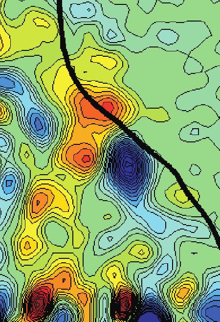
 Contours of vorticity (ω z ) between -1200 s 1 (blue) and 1200s 1 (red). Flame contour in black. Figure 4.")


 1/2, subfigure a) and vortical structures (ω z, subfigure")
 shows a t profiles along the flame surface at selected times. In both cases only the flame segments in the boxed regions of Figs.")


) interacted with the flame. The maximum value of S was 1200s 1, while the vorticity peaks were 1520s 1 and -1130s 1. From Fig.")


. However, the strain-rate structure was attenuated much more quickly than in Interaction 1. As a consequence Fig.")
7 V. Results and Discussion (a) Contours of strain rate (S) between 0 s 1 and 1200 s 1. Flame contour in yellow. (b) Contours of vorticity (ω z ) between s 1 (blue) and 1200s 1 (red). Flame contour in black. Figure 4. Interaction 1 - A strong strain-rate structure and strong vortical structures interact with the flame. Considerable flame surface area is generated and a large wrinkle forms. Field of view is 6 mm x 9 mm, time between frames is 0.9ms. Reactants on left. Bulk flow is upward. The analysis of Sec. II indicates that the turbulent structures responsible for the generation of flame surface area are those associated with concentrated fluid dynamic strain rate, not vorticity. The interaction between fluid with high vorticity and negligible strain rate should have no significant effect on the flame surface area. To demonstrate this, Figs. 4-6 (Interactions 1-3) present the interaction between various turbulent structures and the flame front. In all cases, strain-rate structures (S = resolved component of (S ij S ij ) 1/2, subfigure a) and vortical structures (ω z, subfigure b) are shown separately. Additionally, Fig. 7(a) shows the temporal evolution of the maximum a t for each interaction, while Fig. 7(b) shows a t profiles along the flame surface at selected times. In both cases only the flame segments in the boxed regions of Figs. 4-6 were considered. It should be noted that the flame front manifests itself in the S fields as a region of high strain due to the acceleration of the gas through the flame (i.e. u > 0). However, this strain rate is not a result of the turbulence and hence not the focus of this work. Nevertheless, the high acceleration region is an indicator of the flame thickness and the accuracy of the leading edge isocontour. During Interaction 1, a strong strain-rate structure (Fig. 4(a)) and an associated pair of vortices (Fig. 4(b)) interacted with the flame. The maximum value of S was 1200s 1, while the vorticity peaks were 1520s 1 and -1130s 1. From Fig. 7(a) it is apparent that this interaction exerted a high magnitude strain rate on the flame for an extended period. This produced considerable flame surface area, which was wrapped around the pair of vortices forming a large wrinkle. The long duration of the strain rate on the flame corresponds to the long residence time of the strain-rate structure. In contrast, Interaction 2 (Fig. 5) involved vortical structures of greater strength (1730s 1 and -1810s 1 peak vorticity) and a similar strainrate structure (1220s 1 peak S). However, the strain-rate structure was attenuated much more quickly than in Interaction 1. As a consequence Fig. 7(a) shows that a t for this interaction quickly decreased. Hence, this interaction produced less flame surface area than Interaction 1 and a smaller wrinkle was formed. Finally, Interaction 3 (Fig. 6) contained similar vortical structures to the previous two. However, the configuration was such that the strain-rate structure was not adjacent to the flame when the vortices begin to interact. By the time the strain-rate structure reached the flame, it was nearly attenuated. The resultant a t in Fig. 7(a) was low and nearly no flame surface area was created. Furthermore, the geometry of the flame and vortices 7 of 13
")


")
 and 1200s 1")


8 (a) Contours of strain rate (S) between 0 s 1 and 1200 s 1. Flame contour in yellow. (b) Contours of vorticity (ω z ) between s 1 (blue) and 1200s 1 (red). Flame contour in black. Figure 5. Interaction 2 - A strong strain-rate structure and strong vortical structures interact with the flame. The strain-rate structure is quickly attenuated. A moderate amount of flame surface is generated and a medium sized wrinkle forms. Field of view is 6 mm x 9 mm, time between frames is 0.9ms. Reactants on left. (a) Contours of strain rate (S) between 0 s 1 and 1200 s 1. Flame contour in yellow. (b) Contours of vorticity (ω z ) between s 1 (blue) and 1200s 1 (red). Flame contour in black. Figure 6. Interaction 3 - Strong vortical structures interact with the flame. The strain-rate structure is attenuated before interacting. No flame surface is generated and no wrinkle is formed. Field of view is 6 mm x 9 mm, time between frames is 0.9ms. Reactants on left. 8 of 13
9 was such that the flame surface was not wrinkled; the flame was already oriented around the vortices and the interaction had little effect. Hence, it is apparent that the interaction between turbulence and a flame front is a simultaneous process of strain-rate structures generating flame surface area and vortical structures redistributing it into wrinkles Interaction 1 Interaction 2 Interaction Interaction 1-t=0.18ms Interaction 1-t=0.36ms Interaction 2-t=0.09ms Interaction 2-t=0.27ms at (s -1 ) at (s -1 ) time (ms) (a) Temporal evolution of the strain rate on the flame surface (a t ) ξ/l f (b) Flame strain rate (a t ) profiles measured along the flame surface at various times. Figure 7. Figure 7(b) shows the distribution of strain rate on the flame surface at select times. At each time, only the flame surface in the boxed region is considered. The horizontal coordinate is the distance along the flame surface (ξ) normalized by the length of the flame segment (l f ) in the box. As can be seen, the location of the flame strain rate coincides with the location of the strain-rate structures. For example, Interaction 1 contains a single peak of strain rate throughout, while Interaction 2 develops two peaks coinciding with the locations of the split strain-rate structures at t = 0.27 ms (fourth frame of Fig. 5). Hence, the straining of the flame surface is well characterized by the strength, location, and residence time of the strain-rate structures. This concept of simultaneous straining and wrinkling of flame surface by different structures allows the complex turbulence-flame interactions encountered in practical flows to be analyzed; the assumption that the turbulence exists as isolated counter-rotating vortex pairs is unnecessary. For example, consider the interaction shown in Fig. 8. In this case, there are several vortical structures interacting with the flame simultaneously. This geometry is not considered in the canonical configuration. However, when viewed in terms of strain rate, there are several distinct strain-rate structures, each of which interacts with the flame in isolation. Furthermore, significant strain on the flame is exerted by only two structures and flame surface area is generated at these locations. The resultant wrinkle forms around the group of vortices associated with the two significant strain-rate structures. While the flame straining and wrinkling processes are continuously and simultaneously occurring, it is possible to largely isolate each mechanism to observe their distinct effects. Interactions demonstrating these mechanisms are shown in Figs. 9 and 10. The resulting maximum a t and flame curvature (C) are shown in Fig. 11. Figure 9 (Interaction 5) shows the interaction between two strain-rate structures and the flame front. The vortical structures in this interaction were configured such that no flame wrinkle was produced; the flame surface was already oriented around the vortices. However, the extensively straining structures still exerted strain on the flame surface, generating surface area and resulting in a longer flat flame contour. This is confirmed by Fig. 11. In Fig. 11(a), two pulses of a t are exerted on the flame corresponding to the two strain-rate structures. However, the turbulence does not generate a wrinkle. Figure 11(b) shows that the initial slightly positive curvature is stretched out, resulting in a flatter flame front. This process is analogous to the counterflow geometry of Fig. 2(b). Conversely, Fig. 10 (Interaction 6) shows a vortex pair interacting with the flame. The structure with positive vorticity is considerably stronger than its counterpart. The strain rate structure is also weak. As the positive vortex encounters the flame, existing flame surface is wrapped around it The weaker, negative 9 of 13
")


")
 and 1200s 1")


10 (a) Contours of strain rate (S) between 0 s 1 and 1200 s 1. Flame contour in yellow. (b) Contours of vorticity (ω z) between s 1 (blue) and 1200s 1 (red). Flame contour in black. Figure 8. Interaction 4 - A complicated vorticity field interacts with the flame. However, the generation of flame surface area is easily understood in terms of the strain-rate structures. Field of view is 6 mm x 9 mm, time between frames is 0.9ms. Reactants on left. (a) Contours of strain rate (S) between 0 s 1 and 1200 s 1. Flame contour in yellow. (b) Contours of vorticity (ω z ) between s 1 (blue) and 1200s 1 (red). Flame contour in black. Figure 9. Interaction 5 - Strain-rate structures elongating a flat flame segment. Flame surface area is generated without a wrinkle begin formed. Field of view is 6 mm x 9 mm, time between frames is 0.9ms. Reactants on left. 10 of 13
 Contours of vorticity (ω z ) between -1200 s 1 (blue) and 1200s 1 (red). Flame contour in black. Figure 10.")


.")


11 (a) Contours of strain rate (S) between 0 s 1 and 1200 s 1. Flame contour in yellow. (b) Contours of vorticity (ω z ) between s 1 (blue) and 1200s 1 (red). Flame contour in black. Figure 10. Interaction 6 - A strong vortical structure wraps existing flame surface around it. Little flame surface area is generated. Field of view is 6 mm x 9 mm, time between frames is 0.9ms. Reactants on left. vortex similarly influences the flame, but to a much lesser extent and a non-symmetric wrinkle is formed. However, due to the weak strain rate structure, the a t exerted on the flame is relatively low throughout the interaction as shown in Fig. 11(a). The flame surface is wrapped up by the vortices resulting in a negative curvature wrinkle (Fig. 11(b)). Hence, this wrinkle is formed without significant straining of the flame surface. VI. Conclusions The interaction between a turbulent flow and a premixed flame has been studied experimentally using Cinema-Stereoscopic PIV (CS-PIV). This diagnostic captures the evolution of the flow field and flame front position with high spatial and temporal resolution. A methane-air slot Bunsen flame with coflowing flat pilot flames was studied. The equivalence ratio was 0.7 and the bulk velocity was 1m/s. Analysis of the strain rate term of the flame surface density equation indicated that the turbulent structures responsible for the generation of flame surface area are those of concentrated fluid dynamic strain rate, not vorticity. This is in contrast to the canonical idea of flame wrinkling by vortical structures. A new interpretation of the wrinkling process involving the simultaneous stretching of the flame by turbulent strain-rate structures and redistribution of the flame surface into wrinkles by vortical structures was presented. This interpretation was confirmed using the CS-PIV measurements. It was shown that the generation of large strain rates on the flame corresponded to interactions involving strong strain-rate structures interacting with the flame for extensive time periods. As the strength or interaction time of the strain-rate structures decreased, the amount of flame surface generated and the size of the flame wrinkles also decreased. Hence, the turbulent strain-rate structures provide a good characterization for the strength, duration, and location of the flame surface generation. Furthermore, it was shown that the new interpretation of the straining and wrinkling process is more versatile than the canonical interpretation. A complex flow involving many closely spaced vortical structures was observed. This geometry is not considered by the canonical configuration. However, when viewed in terms of strain-rate structures, the complex geometry devolves into simple interactions between isolated structures and the flame. The effects of strain-rate structures and vortical structures in isolation also were observed. The strain-rate structures interacted with the flame in a manner similar to 11 of 13
12 at (s -1 ) Interaction 5 Interaction time (ms) (a) Strain rate. C (mm -1 ) Interaction 5 Interaction time(ms) (b) Flame curvature. Figure 11. Temporal evolution of the maximum strain rate and flame curvature for Interactions 5 and 6. that of a counterflow flame. Flame surface area appeared to be generated without a wrinkle being formed; the planar flame segment was stretched and elongated. The vortical structures wrapped the flame around themselves, creating a wrinkle without appearing to generate flame surface area. Appendix A general transport equation for the strain rate components in a reacting flow can be derived by taking the spatial derivative the equations for conservation of momentum: u i x j t + ( ) u i u k = g ( ) 1 p + ( ) ν 2 u i (9) x j x k x j x j ρ x i x j x k x k Setting A ij = u i / x j, this can be expanded as: A ij t + u k A ij x k = A ik A kj 1 2 p + 1 p ρ x i x j ρ 2 x i ρ x j + ν 2 A ij x k x k + ν x j 2 u i x k x k (10) Recognizing that S ij = 1/2(A ij + A ji ), the appropriate forms of Eqn. 10 can be summed to yield: ( ) S ij S ij Aik A kj + A jk A ki + u k = 1 2 p + ν 2 S ij (11) t x k 2 ρ x i x j x k x k + 1 ( p ρ 2ρ 2 + p ) ρ + 1 ( ν 2 u i + ν 2 ) u j (12) x i x j x j x i 2 x j x k x k x i x k x k The first term on the right can be written in terms of S and ω by recognizing that A ij = S ij Ω ij and equating the terms of Ω with the various vorticity components. This yields the final transport equation: S ij t + u k S ij x k = S ik S kj 1 4 (ω iω j δ ij ω k ω k ) 1 2 p + ν 2 S ij (13) ρ x i x j x k x k + 1 ( p ρ 2ρ 2 + p ) ρ + 1 ( ν 2 u i + ν 2 ) u j (14) x i x j x j x i 2 x j x k x k x i x k x k References 1 Marble, F. E. and Broadwell, J. E., The coherent flame model for turbulent chemical reactions, Tech. Rep. TRW-9-PU, Project Squid, Choi, C. R. and Huh, K. Y., Development of a coherent flamelet model for a spark ignited turbulent premixed flame in a closed vessel, Combust. Flame, Vol. 114, No. 3, 1998, pp of 13
13 3 Hawkes, E. R. and Cant, R. S., A flame surface density approach to Large Eddy Simulation of premixed turbulent combustion, Proc. Combust. Inst., Vol. 28, 2000, pp Charlette, F., Meneveau, C., and Veynante, D., A power-law flame wrinkling model for LES of premixed turbulent combustion. Part 1: non-dynamic formulation and initial tests, Combust. Flame, Vol. 131, No. 2, 2002, pp Fureby, C., A fractal flame-wrinkling large eddy simulation model for premixed turbulent combustion, Proc. Combust. Inst., Vol. 30, 2005, pp Poinsot, T., Veynante, D., and Candel, S., Quenching processes and premixed turbulent combustion diagrams, J. Fluid Mech., Vol. 228, 1991, pp Meneveau, C. and Poinsot, T., Stretching and quenching of flamelets in premixed turbulent combustion, Combust. Flame, Vol. 86, No. 4, 1991, pp Colin, O., Ducros, F., Veynante, D., and Poinsot, T., A thickened flame model for large eddy simulations of turbulent premixed combustion, Phys. Fluids, Vol. 12, No. 7, 2000, pp Mueller, C. J., Driscoll, J. F., Reuss, D. L., Drake, M. C., and Rosalik, M. E., Vorticity generation and attenuation as vorticies convect through a flame, Combust. Flame, Vol. 112, No. 3, 1998, pp Sinibaldi, J. O., Mueller, C. J., Tulkki, A. E., and Driscoll, J. F., Suppression of flame wrinkling by buoyancy: the baroclinic stabilization mechanism, AIAA J., Vol. 36, No. 8, 1998, pp Renard, P.-H., Thevenin, D., Rolon, J., and Candel, S., Dynamics of flame/vortex interactions, Prog. Energy Combust. Sci., Vol. 26, 2000, pp Kadowaki, S. and Hasegawa, T., Numerical simulation of dynamics of premxied flames: flame instability and vortexflame interaction, Prog. Energy Comust. Sci., Vol. 31, 2005, pp Steinberg, A. M., Driscoll, J. F., and Ceccio, S. L., Temporal evolution of flame stretch due to turbulence and the hydrodynamic instability, To appear: Proc. Combust. Inst., Vol. 32, Kolmogorov, A. N., A refinement of previous hypotheses concerning the local structure of turbulence in a viscous incompressible fluid at high Reynolds number, J. Fluid Mech., Vol. 13, 1632, pp Boratav, O. N. and Pelz, R. B., Structures and structure functions in the inertial range of turbulence, Phys. Fluids, Vol. 9, 1996, pp Nomura, K. K. and Diamessis, P. J., The interaction of vorticity and rate-of-strain in homogeneous sheared turbulence, Phys. Fluids, Vol. 12, 2000, pp Moisy, F. and Jiménez, J., Geometry and clustering of intense structures in isotropic turbulence, J. Fluid Mech., Vol. 513, 2004, pp Swaminathan, N. and W., G. R., Interaction of turbulence and scalar fields in premixed flames, Phys. Fluids, Vol. 18, 2006, pp Chakraborty, N. and Swaminathan, N., Influence of the Damkoler number on turbulence-scalar interaction in premixed flames. I. Physical insight, Phys. Fluids, Vol. 19, 2007, pp Dahm, W., Scheil, C. M., and Tryggvason, G., Dynamics of vortex interaction with a density interface, J. Fluid Mech., Vol. 205, 1989, pp Steinberg, A. M., Driscoll, J. F., and Ceccio, S. L., Measurements of turbulent premixed flame dynamics using cinemastereoscopic PIV, Exp. Fluids, Vol. 44, 2008, pp Müller, U. C., Bollig, M., and Peters, N., Approximations for burning velocities and Markstein numbers for lean hydrocarbon and methanol flames, Combust. Flame, Vol. 108, No. 3, 1997, pp Williams, F., Combustion Theory, 2nd ed., Addison-Wesley, Reading, USA, Steinberg, A. M., Driscoll, J. F., and Ceccio, S. L., Temporally resolved pseudo 3D measurements of flame strain using orthogonal-plane cinema-stereoscopic PIV, 23rd International Congress on Theoretical and Applied Mechanics, Adelaide, Australia, Amidror, I., Scattered data interpolation methods for electronic imaging systems: a survey, J. Electron. Imaging, Vol. 11, 2002, pp of 13
Flow and added small-scale topologies in a turbulent premixed flame
 Flow and added small-scale topologies in a turbulent premixed flame L. Cifuentes*, A. Kempf* and C. Dopazo** luis.cifuentes@uni-due.de *University of Duisburg-Essen, Chair of Fluid Dynamics, Duisburg -
Simulation of Turbulent Lifted Flames and their Transient Propagation
 25 th ICDERS August 2-7th, 2015 Leeds, UK Simulation of Turbulent Lifted Flames and their Transient Propagation S. Ruan, Z. Chen, N. Swaminathan University of Cambridge Cambridge, UK 1 Introduction Turbulent
Lecture 15. The Turbulent Burning Velocity
 Lecture 15 The Turbulent Burning Velocity 1 The turbulent burning velocity is defined as the average rate of propagation of the flame through the turbulent premixed gas mixture. In the laminar case, solutions
D. VEYNANTE. Introduction à la Combustion Turbulente. Dimanche 30 Mai 2010, 09h00 10h30
 D. VEYNANTE Introduction à la Combustion Turbulente Dimanche 30 Mai 2010, 09h00 10h30 Introduction to turbulent combustion D. Veynante Laboratoire E.M2.C. CNRS - Ecole Centrale Paris Châtenay-Malabry France
FLAME AND EDDY STRUCTURES IN HYDROGEN AIR TURBULENT JET PREMIXED FLAME
 FLAME AND EDDY STRUCTURES IN HYDROGEN AIR TURBULENT JET PREMIXED FLAME M. Shimura, K. Yamawaki, Y.-S. Shim, M. Tanahashi and T. Miyauchi Department of Mechanical and Aerospace Engineering Tokyo Institute
S. Kadowaki, S.H. Kim AND H. Pitsch. 1. Motivation and objectives
 Center for Turbulence Research Annual Research Briefs 2005 325 The dynamics of premixed flames propagating in non-uniform velocity fields: Assessment of the significance of intrinsic instabilities in turbulent
Lecture 9 Laminar Diffusion Flame Configurations
 Lecture 9 Laminar Diffusion Flame Configurations 9.-1 Different Flame Geometries and Single Droplet Burning Solutions for the velocities and the mixture fraction fields for some typical laminar flame configurations.
DIRECT AND INDIRECT MEASUREMENTS OF FLAME SURFACE DENSITY, ORIENTATION, AND CURVATURE FOR PREMIXED TURBULENT COMBUSTION MODELING IN A CRUCIFORM BURNER
 Proceedings of the Combustion Institute, Volume 28, 2000/pp. 383 390 DIRECT AND INDIRECT MEASUREMENTS OF FLAME SURFACE DENSITY, ORIENTATION, AND CURVATURE FOR PREMIXED TURBULENT COMBUSTION MODELING IN
Preliminary Study of the Turbulence Structure in Supersonic Boundary Layers using DNS Data
 35th AIAA Fluid Dynamics Conference, June 6 9, 2005/Toronto,Canada Preliminary Study of the Turbulence Structure in Supersonic Boundary Layers using DNS Data Ellen M. Taylor, M. Pino Martín and Alexander
Lecture 8 Laminar Diffusion Flames: Diffusion Flamelet Theory
 Lecture 8 Laminar Diffusion Flames: Diffusion Flamelet Theory 8.-1 Systems, where fuel and oxidizer enter separately into the combustion chamber. Mixing takes place by convection and diffusion. Only where
Structures of Turbulent Bunsen Flames in the Corrugated-Flamelet Regime
 25 th ICDERS August 2 7, 2015 Leeds, UK Structures of Turbulent Bunsen Flames in the Corrugated-Flamelet Regime Junichi Furukawa and Yasuko Yoshida Department of Mechanical Engineering Tokyo Metropolitan
A G-equation formulation for large-eddy simulation of premixed turbulent combustion
 Center for Turbulence Research Annual Research Briefs 2002 3 A G-equation formulation for large-eddy simulation of premixed turbulent combustion By H. Pitsch 1. Motivation and objectives Premixed turbulent
Thermoacoustic Instabilities Research
 Chapter 3 Thermoacoustic Instabilities Research In this chapter, relevant literature survey of thermoacoustic instabilities research is included. An introduction to the phenomena of thermoacoustic instability
A validation study of the flamelet approach s ability to predict flame structure when fluid mechanics are fully resolved
 Center for Turbulence Research Annual Research Briefs 2009 185 A validation study of the flamelet approach s ability to predict flame structure when fluid mechanics are fully resolved By E. Knudsen AND
Scalar gradient and small-scale structure in turbulent premixed combustion
 Center for Turbulence Research Annual Research Briefs 6 49 Scalar gradient and small-scale structure in turbulent premixed combustion By S. H. Kim AND H. Pitsch. Motivation and objectives The scalar gradient
Simultaneous Velocity and Concentration Measurements of a Turbulent Jet Mixing Flow
 Simultaneous Velocity and Concentration Measurements of a Turbulent Jet Mixing Flow HUI HU, a TETSUO SAGA, b TOSHIO KOBAYASHI, b AND NOBUYUKI TANIGUCHI b a Department of Mechanical Engineering, Michigan
A Ghost-fluid method for large-eddy simulations of premixed combustion in complex geometries
 Center for Turbulence Research Annual Research Briefs 2005 269 A Ghost-fluid method for large-eddy simulations of premixed combustion in complex geometries By V. Moureau, P. Minot, C. Bérat AND H. Pitsch
Lecture 14. Turbulent Combustion. We know what a turbulent flow is, when we see it! it is characterized by disorder, vorticity and mixing.
 Lecture 14 Turbulent Combustion 1 We know what a turbulent flow is, when we see it! it is characterized by disorder, vorticity and mixing. In a fluid flow, turbulence is characterized by fluctuations of
Effects of turbulence and flame instability on flame front evolution
 PHYSICS OF FLUIDS 18, 104105 2006 Effects of turbulence and flame instability on flame front evolution Jiao Yuan, Yiguang Ju, and Chung K. Law a Department of Mechanical and Aerospace Engineering, Princeton
NUMERICAL ANALYSIS OF TURBULENT FLAME IN AN ENCLOSED CHAMBER
 NUMERICAL ANALYSIS OF TURBULENT FLAME IN AN ENCLOSED CHAMBER Naveen Kumar D 1*, Pradeep R 2 and Bhaktavatsala H R 3 1 Assistant Professor Department of Mechanical Engineering, M S Engineering College,
Impact of numerical method on auto-ignition in a temporally evolving mixing layer at various initial conditions
 Journal of Physics: Conference Series PAPER OPEN ACCESS Impact of numerical method on auto-ignition in a temporally evolving mixing layer at various initial conditions To cite this article: A Rosiak and
Representing Turbulence/Chemistry interaction with strained planar premixed
 Representing Turbulence/Chemistry interaction with strained planar premixed flames CES Seminar Andreas Pesch Matr. Nr. 300884 Institut für technische Verbrennung Prof. H. Pitsch Rheinisch-Westfälische
LES of an auto-igniting C 2 H 4 flame DNS
 Center for Turbulence Research Annual Research Briefs 2011 237 LES of an auto-igniting C 2 H 4 flame DNS By E. Knudsen, E. S. Richardson, J. H. Chen AND H. Pitsch 1. Motivation and objectives Large eddy
Effects of Variation of the Flame Area and Natural Damping on Primary Acoustic Instability of Downward Propagating Flames in a Tube
 5 th ICDERS August 7, 015 Leeds, UK Effects of Variation of the Flame Area and Natural Damping on Primary Acoustic Instability of Downward Propagating Flames in a Tube Sung Hwan Yoon and Osamu Fujita Division
SIMULTANEOUS VELOCITY AND CONCENTRATION MEASUREMENTS OF A TURBULENT JET MIXING FLOW
 Proceedings of International Symposium on Visualization and Image in Transport Phenomena, Turkey, -9 Oct. SIMULTANEOUS VELOCITY AND CONCENTRATION MEASUREMENTS OF A TURBULENT JET MIXING FLOW Hui HU a, Tetsuo
J. E. Rehm and N. T. Clemens
 AIAA-99-676 The Association of Scalar Dissipation Rate Layers and OH Zones with Strain, Vorticity, and 2-D Dilatation Fields in Turbulent Nonpremixed Jets and Jet Flames J. E. Rehm and N. T. Clemens Center
Large eddy simulation of hydrogen-air propagating flames
 Loughborough University Institutional Repository Large eddy simulation of hydrogen-air propagating flames This item was submitted to Loughborough University's Institutional Repository by the/an author.
Measured properties of turbulent premixed flames for model assessment, including burning velocities, stretch rates, and surface densities
 Combustion and Flame 141 (2005) 1 21 www.elsevier.com/locate/combustflame Measured properties of turbulent premixed flames for model assessment, including burning velocities, stretch rates, and surface
Dynamics of the Coarse-Grained Vorticity
 (B) Dynamics of the Coarse-Grained Vorticity See T & L, Section 3.3 Since our interest is mainly in inertial-range turbulence dynamics, we shall consider first the equations of the coarse-grained vorticity.
A Priori Model for the Effective Lewis Numbers in Premixed Turbulent Flames
 Paper # 070LT-0267 Topic: Turbulent Flames 8 th US National Combustion Meeting Organized by the Western States Section of the Combustion Institute and hosted by the University of Utah May 19-22, 2013.
Measurements of the three-dimensional scalar dissipation rate in gas-phase planar turbulent jets
 Center for Turbulence Research Annual Research Briefs 1998 35 Measurements of the three-dimensional scalar dissipation rate in gas-phase planar turbulent jets By L. K. Su 1. Motivation and objectives The
DNS and LES of Turbulent Combustion
 Computational Fluid Dynamics In Chemical Reaction Engineering IV June 19-24, 2005 Barga, Italy DNS and LES of Turbulent Combustion Luc Vervisch INSA de Rouen, IUF, CORIA-CNRS Pascale Domingo, Julien Réveillon
Large-Eddy Simulation of Turbulent Flames in Syn-Gas Fuel-Air Mixtures
 45th AIAA Aerospace Sciences Meeting and Exhibit 8-11 January 2007, Reno, Nevada AIAA 2007-1435 Large-Eddy Simulation of Turbulent Flames in Syn-Gas Fuel-Air Mixtures Baris A. Sen and Suresh Menon School
Subgrid-scale mixing of mixture fraction, temperature, and species mass fractions in turbulent partially premixed flames
 Available online at www.sciencedirect.com Proceedings of the Combustion Institute 34 (2013) 1231 1239 Proceedings of the Combustion Institute www.elsevier.com/locate/proci Subgrid-scale mixing of mixture
Insights into Model Assumptions and Road to Model Validation for Turbulent Combustion
 Insights into Model Assumptions and Road to Model Validation for Turbulent Combustion Venke Sankaran AFRL/RQR 2015 AFRL/RQR Basic Research Review UCLA Jan 20, 2015 AFTC PA Release# 15011, 16 Jan 2015 Goals
Exercises in Combustion Technology
 Exercises in Combustion Technology Exercise 4: Turbulent Premixed Flames Turbulent Flow: Task 1: Estimation of Turbulence Quantities Borghi-Peters diagram for premixed combustion Task 2: Derivation of
Modeling flame brush thickness in premixed turbulent combustion
 Center for Turbulence Research Proceedings of the Summer Program 2006 299 Modeling flame brush thickness in premixed turbulent combustion By E. Knudsen, O. Kurenkov, S. Kim, M. Oberlack AND H. Pitsch Turbulent
Turbulent Boundary Layers & Turbulence Models. Lecture 09
 Turbulent Boundary Layers & Turbulence Models Lecture 09 The turbulent boundary layer In turbulent flow, the boundary layer is defined as the thin region on the surface of a body in which viscous effects
CHAPTER 7 SEVERAL FORMS OF THE EQUATIONS OF MOTION
 CHAPTER 7 SEVERAL FORMS OF THE EQUATIONS OF MOTION 7.1 THE NAVIER-STOKES EQUATIONS Under the assumption of a Newtonian stress-rate-of-strain constitutive equation and a linear, thermally conductive medium,
Budget analysis and model-assessment of the flamelet-formulation: Application to a reacting jet-in-cross-flow
 Center for Turbulence Research Proceedings of the Summer Program 212 397 Budget analysis and model-assessment of the flamelet-formulation: Application to a reacting jet-in-cross-flow By W. L. Chan, Y.
Application of FGM to DNS of premixed turbulent spherical flames
 Application of FGM to DNS of premixed turbulent spherical flames R.J.M. Bastiaans, G.R.A Groot, J.A. van Oijen and L.P.H. de Goey, Section Combustion Technology, Department of Mechanical Engineering, Eindhoven
The interaction of vorticity and rate-of-strain in homogeneous sheared turbulence
 PHYSICS OF FLUIDS VOLUME 12, NUMBER 4 APRIL 2000 The interaction of vorticity and rate-of-strain in homogeneous sheared turbulence K. K. Nomura a) and P. J. Diamessis Department of Mechanical and Aerospace
FLAME WRINKLING FACTOR DYNAMIC MODELING FOR LARGE EDDY SIMULATIONS OF TURBULENT PREMIXED COMBUSTION
 August 8 -, Poitiers, France FLAME WRINKLING FACTOR DYNAMIC MODELING FOR LARGE EDDY SIMULATIONS OF TURBULENT PREMIXED COMBUSTION Thomas Schmitt, Matthieu Boileau, Denis Veynante Laboratoire EMC CNRS -
Asymptotic Structure of Rich Methane-Air Flames
 Asymptotic Structure of Rich Methane-Air Flames K. SESHADRI* Center for Energy and Combustion Research, Department of Mechanical and Aerospace Engineering, University of California at San Diego, La Jolla,
Large-eddy simulation of an industrial furnace with a cross-flow-jet combustion system
 Center for Turbulence Research Annual Research Briefs 2007 231 Large-eddy simulation of an industrial furnace with a cross-flow-jet combustion system By L. Wang AND H. Pitsch 1. Motivation and objectives
Coupling tabulated chemistry with large-eddy simulation of turbulent reactive flows
 Center for Turbulence Research Proceedings of the Summer Program 2008 237 Coupling tabulated chemistry with large-eddy simulation of turbulent reactive flows By R. Vicquelin, B. Fiorina, N. Darabiha, D.
Flamelet Analysis of Turbulent Combustion
 Flamelet Analysis of Turbulent Combustion R.J.M. Bastiaans,2, S.M. Martin, H. Pitsch,J.A.vanOijen 2, and L.P.H. de Goey 2 Center for Turbulence Research, Stanford University, CA 9435, USA 2 Eindhoven University
Rouen LBV 2012 ACCURACY OF TWO METHODS TO MEASURE LAMINAR FLAME SPEEDS: (1) STEADY BUNSEN BURNER FLAMES AND (2) SPHERICAL FLAMES IN BOMBS.
 STEADY BUNSEN BURNER FLAMES AND (2) SPHERICAL FLAMES IN BOMBS.") Rouen LBV 2012 ACCURACY OF TWO METHODS TO MEASURE LAMINAR FLAME SPEEDS: (1) STEADY BUNSEN BURNER FLAMES AND (2) SPHERICAL FLAMES IN BOMBS. A. Bonhomme, T. Boushaki*, L. Selle, B. Ferret and T. Poinsot
Rouen LBV 2012 ACCURACY OF TWO METHODS TO MEASURE LAMINAR FLAME SPEEDS: (1) STEADY BUNSEN BURNER FLAMES AND (2) SPHERICAL FLAMES IN BOMBS. A. Bonhomme, T. Boushaki*, L. Selle, B. Ferret and T. Poinsot
Before we consider two canonical turbulent flows we need a general description of turbulence.
 Chapter 2 Canonical Turbulent Flows Before we consider two canonical turbulent flows we need a general description of turbulence. 2.1 A Brief Introduction to Turbulence One way of looking at turbulent
Large-eddy simulations of turbulent reacting stagnation point flows
 Copyright 1997, American Institute of Aeronautics and Astronautics, Inc. AIAA Meeting Papers on Disc, January 1997 A9715437, AIAA Paper 97-0372 Large-eddy simulations of turbulent reacting stagnation point
Dynamics of Lean Premixed Systems: Measurements for Large Eddy Simulation
 Dynamics of Lean Premixed Systems: Measurements for Large Eddy Simulation D. Galley 1,2, A. Pubill Melsió 2, S. Ducruix 2, F. Lacas 2 and D. Veynante 2 Y. Sommerer 3 and T. Poinsot 3 1 SNECMA Moteurs,
Topology and Brush Thickness of Turbulent Premixed V-shaped Flames
 Flow Turbulence Combust (2014) 93:439 459 DOI 10.1007/s10494-014-9563-3 Topology and Brush Thickness of Turbulent Premixed V-shaped Flames S. Kheirkhah Ö. L. Gülder Received: 19 December 2013 / Accepted:
A comparison between two different Flamelet reduced order manifolds for non-premixed turbulent flames
 8 th U. S. National Combustion Meeting Organized by the Western States Section of the Combustion Institute and hosted by the University of Utah May 19-22, 2013 A comparison between two different Flamelet
Investigation of ignition dynamics in a H2/air mixing layer with an embedded vortex
 Paper # 070LT-0211 The 8th US National Meeting of the Combustion Institute, Park City, UT, May 19-22, 2013 Investigation of ignition dynamics in a H2/air mixing layer with an embedded vortex S.K. Menon
TOPICAL PROBLEMS OF FLUID MECHANICS 97
 TOPICAL PROBLEMS OF FLUID MECHANICS 97 DOI: http://dx.doi.org/10.14311/tpfm.2016.014 DESIGN OF COMBUSTION CHAMBER FOR FLAME FRONT VISUALISATION AND FIRST NUMERICAL SIMULATION J. Kouba, J. Novotný, J. Nožička
Flame Propagation in Poiseuille Flow under Adiabatic Conditions
 Flame Propagation in Poiseuille Flow under Adiabatic Conditions J. DAOU and M. MATALON* Department of Engineering Sciences and Applied Mathematics, Northwestern University, Evanston, IL 60208-3125, USA
The Effect of Mixture Fraction on Edge Flame Propagation Speed
 8 th U. S. National Combustion Meeting Organized by the Western States Section of the Combustion Institute and hosted by the University of Utah May 19-22, 213 The Effect of Mixture Fraction on Edge Flame
Turbulent Premixed Combustion
 Turbulent Premixed Combustion Combustion Summer School 2018 Prof. Dr.-Ing. Heinz Pitsch Example: LES of a stationary gas turbine velocity field flame 2 Course Overview Part II: Turbulent Combustion Turbulence
6 VORTICITY DYNAMICS 41
 6 VORTICITY DYNAMICS 41 6 VORTICITY DYNAMICS As mentioned in the introduction, turbulence is rotational and characterized by large uctuations in vorticity. In this section we would like to identify some
Combustion basics... We are discussing gaseous combustion in a mixture of perfect gases containing N species indexed with k=1 to N:
 Combustion basics... T. Poinsot poinsot@imft.fr Only the things you should know to understand the following courses Mainly elements of laminar flame theory for premixed and diffusion flames 1 Copyright
2D Direct Numerical Simulation of methane/air turbulent premixed flames under high turbulence intensity Julien Savre 04/13/2011
 1 2D Direct Numerical Simulation of methane/air turbulent premixed flames under high turbulence intensity Julien Savre 04/13/2011 2 Outline Why studying turbulent premixed flames under high turbulent intensity?
Numerical Simulation of Premixed V-Flame
 Proceedings of the World Congress on Engineering 7 Vol II WCE 7, July -, 7, London, U.K. Numerical Simulation of Premixed V-Flame C.K. Chan, B. Stewart, and C.W. Leung Abstract A Lagrangian front-tracking
Pressure and Fuel Effects on the Flame Brush Thickness of H 2 /CO Flames
 Paper # 070LT-0011 Topic: Laminar & Turbulent Flames 8 th U. S. National Combustion Meeting Organized by the Western States Section of the Combustion Institute And hosted by the University of Utah May19-22,
Chuichi Arakawa Graduate School of Interdisciplinary Information Studies, the University of Tokyo. Chuichi Arakawa
 Direct Numerical Simulations of Fundamental Turbulent Flows with the Largest Grid Numbers in the World and its Application of Modeling for Engineering Turbulent Flows Project Representative Chuichi Arakawa
Advanced near-wall heat transfer modeling for in-cylinder flows
 International Multidimensional Engine Modeling User s Group Meeting at the SAE Congress April 20, 2015 Detroit, MI S. Šarić, B. Basara AVL List GmbH Advanced near-wall heat transfer modeling for in-cylinder
Analysis of dynamic models for turbulent premixed combustion
 Center for Turbulence Research Proceedings of the Summer Program 2012 387 Analysis of dynamic models for turbulent premixed combustion By D. Veynante, T. Schmitt, M. Boileau AND V. Moureau Very few attempts
DEVELOPMENT OF CFD MODEL FOR A SWIRL STABILIZED SPRAY COMBUSTOR
 DRAFT Proceedings of ASME IMECE: International Mechanical Engineering Conference & Exposition Chicago, Illinois Nov. 5-10, 2006 IMECE2006-14867 DEVELOPMENT OF CFD MODEL FOR A SWIRL STABILIZED SPRAY COMBUSTOR
Direct numerical simulation of a turbulent reacting jet
 Center for Turbulence Research Annual Research Briefs 999 59 Direct numerical simulation of a turbulent reacting jet By B. J. Boersma. Motivation and objectives Turbulent reacting jets are important in
Turbulence Modeling I!
 Outline! Turbulence Modeling I! Grétar Tryggvason! Spring 2010! Why turbulence modeling! Reynolds Averaged Numerical Simulations! Zero and One equation models! Two equations models! Model predictions!
An Introduction to Theories of Turbulence. James Glimm Stony Brook University
 An Introduction to Theories of Turbulence James Glimm Stony Brook University Topics not included (recent papers/theses, open for discussion during this visit) 1. Turbulent combustion 2. Turbulent mixing
Experimental results on the stabilization of lifted jet diffusion flames
 Center for Turbulence Research Annual Research Briefs 2 79 Experimental results on the stabilization of lifted jet diffusion flames By L. K. Su, D. Han AND M. G. Mungal 1. Motivation and objectives Many
ANSYS Advanced Solutions for Gas Turbine Combustion. Gilles Eggenspieler 2011 ANSYS, Inc.
 ANSYS Advanced Solutions for Gas Turbine Combustion Gilles Eggenspieler ANSYS, Inc. 1 Agenda Steady State: New and Existing Capabilities Reduced Order Combustion Models Finite-Rate Chemistry Models Chemistry
Combustion. Indian Institute of Science Bangalore
 Combustion Indian Institute of Science Bangalore Combustion Applies to a large variety of natural and artificial processes Source of energy for most of the applications today Involves exothermic chemical
CFD Analysis of Vented Lean Hydrogen Deflagrations in an ISO Container
 35 th UKELG Meeting, Spadeadam, 10-12 Oct. 2017 CFD Analysis of Vented Lean Hydrogen Deflagrations in an ISO Container Vendra C. Madhav Rao & Jennifer X. Wen Warwick FIRE, School of Engineering University
Faculty of Engineering. Contents. Introduction
 Faculty of Engineering Contents Lean Premixed Turbulent Flames vs. Hydrogen Explosion: A Short Survey on Experimental, Theoretical and Analytical Studies Dr.-Ing. Siva P R Muppala Lecturer Prof. Jennifer
Large Eddy Simulation of Flame Flashback by Combustion Induced Vortex Breakdown
 June 30 - July 3, 2015 Melbourne, Australia 9 1C-5 Large Eddy Simulation of Flame Flashback by Combustion Induced Vortex Breakdown Eike Tangermann Institut für Mathematik und Rechneranwendung Universität
Progress towards a large eddy simulation of premixed turbulent combustion in stagnating turbulence
 Center for Turbulence Research Annual Research Briefs 999 9 Progress towards a large eddy simulation of premixed turbulent combustion in stagnating turbulence By D. S. Louch. Motivation and objectives
LES Approaches to Combustion
 LES Approaches to combustion LES Approaches to combustion LES Approaches to Combustion W P Jones Department of Mechanical Engineering Imperial College London Exhibition Road London SW7 2AZ SIG on Combustion
A Jet-Stirred Apparatus for Turbulent Combustion Experiments
 25 th ICDERS August 2 7, 2015 Leeds, UK A Jet-Stirred Apparatus for Turbulent Combustion Experiments Abbasali A. Davani; Paul D. Ronney University of Southern California Los Angeles, California, United
Analysis of lift-off height and structure of n-heptane tribrachial flames in laminar jet configuration
 Analysis of lift-off height and structure of n-heptane tribrachial flames in laminar jet configuration Stefano Luca*, Fabrizio Bisetti Clean Combustion Research Center, King Abdullah University of Science
Max Planck Institut für Plasmaphysik
 ASDEX Upgrade Max Planck Institut für Plasmaphysik 2D Fluid Turbulence Florian Merz Seminar on Turbulence, 08.09.05 2D turbulence? strictly speaking, there are no two-dimensional flows in nature approximately
Flame / wall interaction and maximum wall heat fluxes in diffusion burners
 Flame / wall interaction and maximum wall heat fluxes in diffusion burners de Lataillade A. 1, Dabireau F. 1, Cuenot B. 1 and Poinsot T. 1 2 June 5, 2002 1 CERFACS 42 Avenue Coriolis 31057 TOULOUSE CEDEX
School of Aerospace Engineering. Course Outline
 Course Outline A) Introduction and Outlook B) Flame Aerodynamics and Flashback C) Flame Stretch, Edge Flames, and Flame Stabilization Concepts D) Disturbance Propagation and Generation in Reacting Flows
FLAME SURFACE DENSITIES IN PREMIXED COMBUSTION AT MEDIUM TO HIGH TURBULENCE INTENSITIES
 Combust. Sci. and Tech., 179: 191 206, 2007 Copyright Q Taylor & Francis Group, LLC ISSN: 0010-2202 print/1563-521x online DOI: 10.1080/00102200600808722 FLAME SURFACE DENSITIES IN PREMIXED COMBUSTION
Experimental analysis and large eddy simulation to determine the response of non premixed flame submitted to acoustic forcing
 Experimental analysis and large eddy simulation to determine the response of non premixed flame submitted to acoustic forcing B. Varoquié, J.P. Légier, F. Lacas, D. Veynante and T. Poinsot Laboratoire
Evaluation of Numerical Turbulent Combustion Models Using Flame Speed Measurements from a Recently Developed Fan- Stirred Explosion Vessel
 Paper # 070LT-0096 Topic: Turbulent Flames 8 th U. S. National Combustion Meeting Organized by the Western States Section of the Combustion Institute and hosted by the University of Utah May 19-22, 2013
Characterizing the regimes of spray flame-vortex interactions: A spray spectral diagram for extinction
 Center for Turbulence Research Annual Research Briefs 2014 265 Characterizing the regimes of spray flame-vortex interactions: A spray spectral diagram for extinction By B. Franzelli, A. Vié AND M. Ihme
THE DOMAIN OF INFLUENCE OF FLAME INSTABILITIES IN TURBULENT PREMIXED COMBUSTION
 Twenty-Seventh Symposium (International) on Combustion/The Combustion Institute, 1998/pp. 971 978 THE DOMAIN OF INFLUENCE OF FLAME INSTABILITIES IN TURBULENT PREMIXED COMBUSTION H. BOUGHANEM and A. TROUVÉ
Numerical simulation of turbulent combustion using RANS - LES models and flamelet generated manifolds Fancello, A.; Bastiaans, R.J.M.; de Goey, L.P.H.
 Numerical simulation of turbulent combustion using RANS - LES models and flamelet generated manifolds Fancello, A.; Bastiaans, R.J.M.; de Goey, L.P.H. Published: 01/01/2011 Document Version Accepted manuscript
O. A Survey of Critical Experiments
 O. A Survey of Critical Experiments 1 (A) Visualizations of Turbulent Flow Figure 1: Van Dyke, Album of Fluid Motion #152. Generation of turbulence by a grid. Smoke wires show a uniform laminar stream
An Unsteady/Flamelet Progress Variable Method for LES of Nonpremixed Turbulent Combustion
 43rd AIAA Aerospace Sciences Meeting and Exhibit, -3 Jan 25, Reno, NV An Unsteady/Flamelet Progress Variable Method for LES of Nonpremixed Turbulent Combustion Heinz Pitsch and Matthias Ihme Stanford University,
Effects of Damköhler number on flame extinction and reignition in turbulent nonpremixed flames using DNS
 Effects of Damköhler number on flame extinction and reignition in turbulent nonpremixed flames using DNS David O. Lignell a,, Jacqueline H. Chen b, Hans A. Schmutz a a Chemical Engineering Department,
Numerical Simulation of Pollutant Emission and Flame Extinction in Lean Premixed Systems. Gilles Eggenspieler
 Numerical Simulation of Pollutant Emission and Flame Extinction in Lean Premixed Systems A Thesis Presented to The Academic Faculty by Gilles Eggenspieler In Partial Fulfillment of the Requirements for
Experimental Study on the Non-reacting Flowfield of a Low Swirl Burner
 Experimental Study on the Non-reacting Flowfield of a Low Swirl Burner Hang Yin & Ren Dai School of Energy and Powering Engineering, University of Shanghai for Science and Technology Box 25, 516# Jungong
6.2 Governing Equations for Natural Convection
 6. Governing Equations for Natural Convection 6..1 Generalized Governing Equations The governing equations for natural convection are special cases of the generalized governing equations that were discussed
DNS STUDY OF TURBULENT HEAT TRANSFER IN A SPANWISE ROTATING SQUARE DUCT
 10 th International Symposium on Turbulence and Shear Flow Phenomena (TSFP10), Chicago, USA, July, 2017 DNS STUDY OF TURBULENT HEAT TRANSFER IN A SPANWISE ROTATING SQUARE DUCT Bing-Chen Wang Department
Investigation of ignition dynamics in a H2/air mixing layer with an embedded vortex
 Paper # 070LT-0211 The 8th US National Meeting of the Combustion Institute, Park City, UT, May 19-22, 2013 Investigation of ignition dynamics in a H2/air mixing layer with an embedded vortex S.K. Menon
Numerical Studies of Supersonic Jet Impingement on a Flat Plate
 Numerical Studies of Supersonic Jet Impingement on a Flat Plate Overset Grid Symposium Dayton, OH Michael R. Brown Principal Engineer, Kratos/Digital Fusion Solutions Inc., Huntsville, AL. October 18,
7 The Navier-Stokes Equations
 18.354/12.27 Spring 214 7 The Navier-Stokes Equations In the previous section, we have seen how one can deduce the general structure of hydrodynamic equations from purely macroscopic considerations and
Convection. forced convection when the flow is caused by external means, such as by a fan, a pump, or atmospheric winds.
 Convection The convection heat transfer mode is comprised of two mechanisms. In addition to energy transfer due to random molecular motion (diffusion), energy is also transferred by the bulk, or macroscopic,