Aging, Cracking and Shaking of Concrete Dams
|
|
|
- Jacob Foster
- 6 years ago
- Views:
Transcription
1 Aging, Cracking and Shaking of Concrete Dams Victor Saouma University of Colorado, Boulder Acknowledgements: Tokyo Electric Power Service Company (TEPSCO)


2 Dams are BIG! 9,000 m, m 2,335 m, 185 m 2
3 Major Issues Cracking: Massive un-reinforced concrete. Aging: Alkali-Aggregate Reactions Shaking: Earthquakes 3
4 Some Relevant Publications 1. Puntel, E., Bolzon, G. Saouma, V., A Fracture mechanics Based Model for Joints Under Cyclic Loading, November 2006, ASCE J. of Engineering Mechanics, Vol. 132, No. 11, pp Puntel, E., Saouma, V., Experimental Behavior of Concrete Joints Under Cyclic Loading, in print, ASCE J. of Structural Engineering, Saouma, V., Perotti, L., Shimpo, T. Stress Analysis of Concrete Structures Subjected to Alkali Aggregate Reactions, American Concrete Institute Structural Journal, Vol. 104, No. 5, pp , September-October, Saouma, V. Perotti, L., Constitutive Model for Alkali Aggregate Reactions, American Concrete Institute, Materials Journal, Vol. 103, No. 3, pp , May- June, Uchita, Y., Shimpo, T., Saouma, V., Dynamic Centrifuge Tests of Concrete Dams, Earthquake Engineering and Structural Dynamics, Vol. 34, pp , Oct Uchita, Y., Noguchi, Y. and Saouma, V. Seismic Dam Safety Research International Water Power \& Dam Construction, pp , Dec Saouma, V., Miura, F., Lebon, G., Yagome, Y., A Simplified 3D Model for Rock- Structure Interaction with Radiation Damping and Free Field, Submitted for Publication. 6. Lebon, G., Saouma, V., Uchita, Y., 3D rock-dam seismic interaction, Dam Engineering, Sept
5 Cracking Aging Shaking 5


6 Joints & Cracks 6


7 Testing Joints; Monotonic Dry Static; Different Sizes Mixed-Mode Dry and Wet Dynamic 7


8 Testing Joint Cyclic 8
9 Interface Crack Model (ICM) At the heart of our numerical model, is an interface/joint element. Hyperbolic Failure Envelope τ 1 1 tan( φ f ) tan( φ f ) c Initial Failure Function Failure Function Final Failure Function ( 1 2) Cohesion and Tensile Strength F Displacement decomposition: Softening parameter: u = τ + τ 2ctan( φ )( σ σ) tan( φ ) ( σ σ ) = f t f t ieff ieff ( ) σt σt ( ) c= cu = u e i i p f u= u + u u = u + u ( u u u ) = u = + + ieff i i i i x y z Irreversible 1 2 Fracturing σ 9


 ( ) 0 Asperity degradation depends")
 y( w ) = f, n t i t")
10 Cyclic Model The asymptotes of the hyperbola rotate of angle α. Analytical expression of an asperity representative of the joint roughness ϕ 2 µ p ( c p µ ) + ( c χ µ ) p 0 β t β n β β β β t µ β+ α = 2 µ β pt cβ pn µ β + cβ χ β µ β pt < µ β α ( ) ( ) 0 Asperity degradation depends on confinement p n and shear work L i t w i n ( i p L ) y( w ) = f, n t i t L = p w i i t t t 10
11 Validation 1: Interface COD (mm) COD Distribution (t=3.260sec) Case3: Linear Case2: Constant COD (mm) COD Distribution (t=4.005sec) Case3: Linear Case2: Constant COD (mm) COD Distribution (t=4.190sec) Case3: Linear Case2: Constant COD (mm) COD Distribution (t=4.230sec) Case3: Linear Case2: Constant Ligament Length (m) Ligament Length (m) Ligament Length (m) Ligament Length (m) Normal Stress Distribution (t=3.260sec) 2 Normal Stress Distribution (t=4.190sec) 2 Normal Stress (MPa) Case3: Linear -8 Case2: Constant Ligament Length (m) Normal Stress (MPa) Case3: Linear -8 Case2: Constant Ligament Length (m) Note: 1. No crack overlap; 2. Crack advances; 3. Cohesive tensile stresses 11


12 Application 1 Diagonal and horizontal cracks t 6 = m t 5 = m t 4 = m t 3 = m t 2 = m t 1 = m Base Concrete 6.06 m 12


13 Laboratory Tests to model reinforced joints 13

14 3D Nonlinear Numerical Simulation 14


15 Crack Modeling 10 buttress-buttress cracks x z y 14 beams 28 beamsbuttress cracks Interface cracks z x y 15


16 16

17 Application 2 17
18 Cracking Aging Shaking 18


19 AAR Over 10 cm US movement since 1940 Over 7.5-cm VERTICAL expansion since 1940 Unit misalignment problems in Powerhouse Alkali-Aggregate Reaction causes an expansion of concrete which may lead to structural cracks Slice the dam to relieve stresses due to expansion Courtesy R. Charlwood 19
20 Reaction is Sensitive to RH What we know Thermodynamically driven (Temperature). Laboratory tests at LCPC have shown that Expansion follows a typical sigmoidal curve Expansion is inhibited in presence of confinement (~8 MPa). There is a redistribution of expansion. Cracks reduce expansion Degradation of tensile strength and Young s modulus 20
21 AAR ( ) ( ' ) ( ' ε ) ( ) ( ) vol t Γt ft w c, σi CODmax Γ c σ, fc f h ξ t, θ ε = t, = 1 e 1 1 τ c( θ) = τc( θ0)exp U C ; θ θ0 ' ' 1 1 τ L( θ, Iσ, fc ) = f( Iσ, fc ) τl( θ0)exp U L ; θ θ0 ε,, τ τ c C t L, I, f 1 C L e t ' c Model 1 if Iσ 0 ' f( Iσ, fc ) = I ; I σ σ = σ + σ + σ 1 + α if I ' σ > I II III 0 3fc U U C L ξ ( t) These parameters must be determined (possibly through an inverse analysis or laboratory Tests) τ L 2 τ c Time [day] θ θ = 5, 400 ± 500 K Activation energy for the char. time = 9, 400 ± 500 K Activation energy for the lat. time f ( h ) m H = 1 in general for dams 0 21
22 TENSION ε AAR vol AAR gel absorption ' ' ( tγ ) = Γ,f ( f fw h, COD ) ( ) ( ) ξ( t, ) t t c σ I max c σ c θ ε θ= θ 0 Tension causes cracks which absorb the gel and inhibit expansion Γ t ' 1 if σi γt ft Linear elastic fictitious γ t ft ' Γr + ( 1 Γr) if γt ft < σi σ I = 1 if CODmax γ twc Smeared crack γ twc Γr + ( 1 Γ) if γ r t w c < COD max COD max ' f t t 1 Linear Analysis t 1 G F Non-Linear Analysis w c r r γ f = f fictitious ' t t t σ I t w c COD max 22
23 COMPRESSION ε AAR vol ' ' ( tγ ) = Γ,f ( f fw h, COD ) ( ) ( ) ξ( t, ) t t c σ I max c σ c θ ε θ= θ 0 Reactive aggregate Crack There is a reduction in expansion under biaxial or triaxial state of stress Gamma 2 versus Hydrostatic stress 1 1 if σ 0 Tension β Γc = e σ 1 if σ 0 Compression β > 1+ ( e 1) σ I II III σ σ + σ + = σ Principal Stresses ' 3 f c Gamma β=-2 β= β=0 0.4 β=1 β= *f 3*f c t Hydrostatic stress [MPa] 23
24 Redistribution of volumetric strain AAR i ε ( t) = W ε ( t) i AAR Vol Assumptions Uniaxial/Biaxial load: the AAR-expansion in direction i is reduced (or eliminated if σ < σ u ) in presence of compression. Triaxial load: the AAR-expansion is reduced in the direction of the highest compression; Note: we can have expansion if f c < σ < σ u ) The AAR volumetric expansion is redistributed into the three principal directions on the basis of the multiaxial state of (principal) stresses. Reduction of AAR volumetric strain accounted for by Γ c 24
/2 W m = (1-W k )/2 W k = 0 W l = 1/2 W m = 1/2 W k =1/2 W l = 0 W m = 1/2 0 < W k < 1/2 W l = 0 W m = 1-W k W k = 0 W l = 0 W m = 1 3 σ 0 σ < σ < 0 σk = σu k u k f < σ < σ ' c k u σ k")
25 k Weights l m Must consider different scenarios; based on f t, σ u and f c 1 σ 0 σ < σ < 0 σk σu 2 σ k 0 σu < σk < 0 σk σu k u k σ l = σ u W k = 1/3 W l =1/3 W m =1/3 0 < W k < 1/3. W l = (1-W k )/2 W m = (1-W k )/2 W k = 0 W l = 1/2 W m = 1/2 W k =1/2 W l = 0 W m = 1/2 0 < W k < 1/2 W l = 0 W m = 1-W k W k = 0 W l = 0 W m = 1 3 σ 0 σ < σ < 0 σk = σu k u k f < σ < σ ' c k u σ k = f c W k = 1 W l = 0 W m = 0 1/3 < W k < 1 W l = (1-W k )/2 W m = (1-W k )/2 W k = 1/3 W l = 1/3 W m = 1/3 σ l = σ u σ m = σ u Wk= 0 W k < 1/3 W l = (1-W k )/2 W m = (1-W k )/2 W l = 1/2 W m = 1/2 25
26 Degradation of Young s modulus and tensile strength ( ) E = E 1 1 β ξ (, θ ) 0 E t β E residual fraction of Young`s modulus ( ) f = β ξ θ,0 1 1 (, ) t ft f t β f residual fraction of tensile strength ξ( t, θ ) = 1 e 1 + e t τ ( θ ) C ( t τl ( θ ) ) τ ( θ ) C E/E 0 ; f t /f t β = β = 70% E f τ lat τ lat +2τ car 0.6 Time Time [days] 26

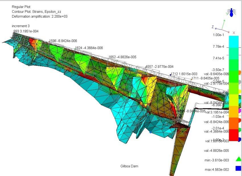
27 Arch-gravity dam. 27

![50 1601.50 Incremental Elevation Incremental Elevation \ \ 8.1155 8.12 8.12 8.12 8.12 8.12 8.12 8.12 Temperature Temperature None AAR AAR None Incremental Elevation Temperature [ o C] AAR Incr.](/docs-images/71/66041865/images/28-2.jpg "Body force Pool Elevation January February March April May June 6 7 7 8 9 10 11 12 13 14 15 16 dam 1596.47 1593.53 1593.53 1592.94 1590.59 1589.71 1588.24 1586.76 1591.47 1598.24 1602.65 1604.")
28 Data Preparation for Stress Analysis Increments Initialization Incr Displacement / Boundary condition Body force Full on the curve 11 Dam Hydrostatic Uplift Pool Elevation Pool Elevation Incremental Elevation Incremental Elevation \ \ Temperature Temperature None AAR AAR None Incremental Elevation Temperature [ o C] AAR Incr. Body force Pool Elevation January February March April May June dam Hydrostatic Uplift Air Water AAR Activated Incremental Elevation Temperature [ o C] AAR Incr. Body force Pool Elevation July August September October November December dam Hydrostatic Uplift Air Water AAR Activated 28

29 Matlab Based System Identification for Key parameters Program Merlin GUI 29


30 Principal stresses: maximum Cracks inside the dam The presence of high tensile stresses inside the dam can explain the origin of the cracks which appeared along the upper gallery. Other cracks can exist inside the dam and may not be yet identified. Crack along the upper gallery Crack inside core borehole in the upper gallery 30


31 Application 2 AAR Localized C b C a c T d T 6,900 3,700 1,500 1,700 c 15,750 2,000 11,750 2,000 1,500 1, d 2,000 8, ,500 1,700 3,000 3,550 c d 8,000 3,000 3,000 b a cable TENSION column D column A Loading a 脚 b 脚 c 脚 d 脚 Units Load T 1.52E E E E+06 N Area m 2 Traction 3.798E E E E+05 Pa 3.798E E E E-01 Mpa column C TENSION transmission cable column B column C,D COMPRESSION column A,B 31


32 Analyses 4.40E-03 Observation Upper side 4.67E-03 C 脚 4.40E E E E E E E E-05 D 脚 (MPa) 9.00E-04 Lower side 4.33E E E E E E E E E E E E-05 解析結果との比較 C 脚 D 脚 Facing North 1.18E E E E E E E E E E E E-05 C C 脚 D 脚 Facing South 3.33E E E E E E E E E E E E E-03 Maximum principal strain D C 脚 C D 脚 32
33 Cracking Aging Shaking 33


34 Earthquakes & Dams 34
35 LOADS Thermal Deconvolution INTERACTIONS Initial Stresses MODELS TESTS APPLICATIONS TOOLS 35
36 Modes of heat transfer in a dam analysis Conductivity T qi = ki x Convection i ( ) qconv = htsurface Tfluid, Time varying prescribed T Reservoir Absorption Incident solar radiation Reflection Convection Radiation 4 4 ( ) qr = ecs Tsurf T fluid, Isolation Dam Foundation Radiation Isolation 36
 earthquake on surface O Must apply the")


37 Deconvolution Details O I Observe (or determine a synthetic) earthquake on surface O Must apply the seismic record at I Must model (elastic) foundation Q: Which record should be applied at base of foundation such that the computed one at O will match the desired earthquake? A: Need to Deconvolute the signal 37
38 ( t) Time Domain; ( ) Frequency Domain (via FFT) 1 -i2 t i2 t X( ) xt () e dt ; x() t X( ) e - - FFT FFT FFT xt () X( ) FFT 1 d FFT FFT -1 i(t) I(ω) Excitation h (t) H (ω) o(t) O(ω) Transfer Function (Fourier Spectral Ratio) (1D) 1. FFT input, I(t) and output O(t) signal to go from time to frequency domain; I(ω) and O(ω); 2. Determine the TF by dividing amplitudes of each frequency of the Output by the corresponding one of the input: TF I-O = O(ω)/ I(ω) 38
 I '( ); a( t) A( ) A( ) 2. TF I '( ) 1 I '( ) 3. I( ) TF A'( ) A'( ) A( ) FFT 1 4.")
39 1D Deconvolution a (t) a(t) Physical model i (t)=a (t) Numerical model i(t)? FFT 1. i'( t) I '( ); a( t) A( ) A( ) 2. TF I '( ) 1 I '( ) 3. I( ) TF A'( ) A'( ) A( ) FFT 1 4. I( ) it ( ) FFT 39

40 Input FFT x Deconvolved FFT x Deconvolution; Frequency X 0.05 Amplitude Frequency Input data x Deconvolved Ix Deconvolution; Time X Acceleration Time 40


 Static Analysis followed by a")

 More")
41 Initial Stress Analysis; Staged Construction Simulation; Static-Dynamic Analysis Weight in one block Staged Construction of individual monoliths (2D) Grouting (3D) Static Analysis followed by a Dynamic Analysis (change in material properties & Boundary Conditions) Excessive Deformation and Stresses (tensile) More realistic initial stresses 41
42 Reservoir-Structure LOADS Fluid-Fracture/Joint INTERACTIONS Foundation-Free Field MODELS TESTS APPLICATIONS TOOLS 42
43 Uplift L = 0 Lcr < Lg cr al Lcr D eff > = L gal 0. L D cr gal eff > L = 1.0 In a nonlinear analysis, uplift is automatically adjusted in accordance with crack opening/failure 43
44 Uplift must be adjusted as crack propagates in a nonlinear analysis; In Dynamic analysis as d(cod)/dt, p and d(cod)/dt, p UDyn U Dynamic Uplift Stat Model must be calibrated with Boulder and Montreal Tests 1 dcod dt 44
45 1 0.8 Initial Uplift on Dam/Foundation Interface Dynamic Uplift Validation Uplift (MPa) We note that: Uplift (MPa) Ligament (m) Uplift Distribution on Dam/Foundation Interface t=0sec t=3.26sec t=4.005sec t=4.19sec t=4.23sec 1. Uplift is non-zero for an open (or previously opened) crack 2. Water/crack front advances with time Ligament (m) 45
46 Base of the dam excited by a seismic wave. Wave will travel through the model, and eventually hit the boundary. As with all waves, it will be reflected by the free surface. In actuality, it keeps propagating in the foundation. Seismic Wave Reflection Reflected wave may either amplify or decrease seismic excitation, in either case, it must be eliminated. Reflection can be eliminated either by a) infinitely large mesh (expensive), b) infinite (boundary) element ; or through Radiation Damping which will absorb the incident waves (P and S). 46
47 Radiation Damping M 0; g 0 M=0; g=0 It is erroneous not to account for the mass in the rock Current Practice 47

48 Lysmer M 0; g 0 Ω C dp s F C M 0; g = 0 C dp n u Ω Lysmer Assumes rigid support, no effect of free field Current Practice 2; Lysmer t = ρvu; t = ρvv; n P s1 S µ 1 V = ; V = V ρ s s S P S 2 1 2ν = 2(1 ν ) ; 48
 ( ) + + Ω u + u + u + + + Ω Ω Ω Ω Ω dp Γ Γ dp Γ Γ dp Ω M C K Clft u lft u lft Crgt u rgt u rgt Cbotu")
49 Free Field Γ - Displacements Velocities u Γ u Γ K S K N C dp n C dp s F K F R F C u Ω Lysmer Γ + Ω Miura-Saouma Analyse Free Field First F F F F F F M u + C u +Κ u = t F F Solve u and u along boundary Γ F Account for free field analysis results, and analyse foundation-structure next ( ) ( ) + + Ω u + u + u Ω Ω Ω Ω Ω dp Γ Γ dp Γ Γ dp Ω M C K Clft u lft u lft Crgt u rgt u rgt Cbotu bot = ( R Γ Γ u + ) ( R Γ Γ ) lft ft Crgtu rgt + K rgtu rgt Ω t bot Clft lft K u l Left Virtual Interface Right Virtual Interface Ω Ω Ω M u C u K u C u C u C u Ω Ω Ω dp Ω dp Ω dp Ω lft lft + lft rgt + bot bot t + F + F + F + F + F + F Ω C K R C K R bot lft lft lft rgt rgt rgt Derived from Principle of Virtual Work = 49

50 Meshing ff, L ff, L { u }, { u } F F ff, R ff, R { u }, { u } dp C bot Free Field Free Field


51 Validation; Harmonic excitation at Base Free Boundaries Lysmer Miura-Saouma 51


52 3D Validation Lysmer Miura-Saouma 52
 53")
53 Effect of Boundary Conditions Criteria Radiation Damping No Lysmer Miura Rocking Yes Yes No No Yes No Gravity Load Transfer Yes Yes No Yes No Yes Perform static analysis with supports Determine reactions Restart a dynamic analysis with initial stress, zeroed displacements, remove supports and replace them by forces (i.e. no BC) 53
54 Case Study STUDY No Rad. Damp. Lysmer Miura Foundation Size BC Type Miura vs Lysmer Small Large Fixed Free f (1, 4, 8 Hz) Interface Effect of E Reaction to Load Comp. (with Interface) E/10 Foundation Size Exact E 10E Small Large No RD; 10% Rayl. Effect of M Effect of M Massless Mass Massless Mass Mesh Size Inter./Ext. Small Medium Interior Exterior Large f (1, 4, 8 Hz) Detailed parametric study of Folsom Dam subjected to harmonic excitation (different frequencies), and 1971 San Fernando Earthquake, 0.30 peak ground acceleration) 54
55 Observations 1. If no radiation damping is present, very large foundations should be used, 2. For soft rock, the mass of the foundation should be modeled as we can have substantial amplification of the input signal. 3. When the mass is modeled, we have a larger inertia and thus slightly reduced dam accelerations. However this effect is mitigated by deconvolution of the input signal which should be performed. 4. Massless foundation will generate larger response than when the foundation mass is accounted for. 5. One should not apply vertical support in a seismic analysis of a massive concrete structures with its foundation as rocking will induce additional accelerations (and stresses). 6. When radiation damping is present we greatly reduce the dependency on the size of the foundation. 7. Even when radiation damping is present, the height of the foundation should be carefully selected to correspond to a multiplier (one should be enough) of the shear wave length. 8. Interface (or joint) elements between the dam and the foundation may not substantially reduce the accelerations but will reduce the stresses. 9. A model based on Saouma-Miura with interface element is equivalent to a simpler model (with no interfaces, no radiation damping) with a Rayleigh damping of about 15%. 55
56 Beaver (Dam Definition) LOADS Pre-Processor: KUMO Analysis: MERLIN INTERACTIONS Post-Processor: SPIDER MODELS Analysis Sequence TESTS APPLICATIONS TOOLS 56

57 MERLIN 57


58 58


59 Profiles_of_crack_002,Crack opening 'C:\Tepsco\Analyses\Kasho-Gravity\Data-Files\3D\kas-3-f-ss_dyn2.xyzvdat' Profiles_of_crack_003,Uplift 2e-07 values 1e-07 'C:\Tepsco\Analyses\Kasho-Gravity\Data-Files\3D\kas-3-f-ss_dyn2.xyzvdat' e-07 values -1.39e-17 2e-07 1e e-07-2e-07-2e-07-3e e Z X Z X -54 Time-Accel_Crv,_Increment_ 'C:\Tepsco\Analyses\Kasho-Gravity\Data-Files\3D\kas-3-f-ss_dyn2.dat' Acceleration Time Time-Accel_Crv,_Increment_555-FFT 1.2 'C:\Tepsco\Analyses\Kasho-Gravity\Data-Files\3D\kas-3-f-ss_dyn2.dat' Acceleration, magnitude Time, frequency 59
 MODELS Centrifuge Dynamic Tests (Detailed) TESTS APPLICATIONS")
60 LOADS INTERACTIONS Boulder Tests (Misc) Centrifuge Dynamic test (Short) MODELS Centrifuge Dynamic Tests (Detailed) TESTS APPLICATIONS TOOLS 60


 Max. Payload: Platform: 3 t 2.2 x 1.")
61 CENTRIFUGE Maxi Payload: 7 t Platform Size: 2.2 x 2.2 m Model Height: 2.5 m Max. Accel. 120 g Max. Payload: 700 g-t Shaking Table 4 Electro-Hydraulic Actuators (1,176 kn Total) Max. Payload: Platform: 3 t 2.2 x 1.07 m Max. Accel. 500 m/s 2 Max. Freq. 200 Hz 61

62 Centrifuge Test of Dam Place Specimen on Shaking table Place shaking table on centrifuge Prototype 100 m 10 sec. Model 1m 0.1 sec. 62
 加振 1 段階当たりの波形イメージ加速度(m/s2) 150 100 50 0-50 -100 0.06 sec 167Hz 漸増正弦波 -150 0 0.02 0.04 0.06 0.08 t(s) 0.")
63 載荷 加振条件 遠心力場 (g) ならし運転空虚時 最大加速度 : 6 段階 加振波形 6 段階で加速度を増加させる 最大加速度 450m/s 2 湛水振動実験 振動実験 満水時 加振波形 :4 段 階 経過時間 (min) 加振 1 段階当たりの波形イメージ加速度(m/s2) sec 167Hz 漸増正弦波 t(s) 0.1 時間 (s) 63
64 基盤に対する天端の伝達関数 第 3 波 増幅率 第 4 波 増幅率 Transfer Functions to Detect Cracks 周波数 (Hz) 周波数 (Hz) 第 5 波 30 第 6 波 増幅率 増幅率 急増 周波数 (Hz) 周波数 (Hz) 64
65 加速度応答の比較 天端 基盤 Acceleration (m/sec 2 ) Acceleration (m/sec 2 ) Time (sec) 解析実験 解析 Anal 実験 ysis Experi ment ( 同定値 ) 弾性係数 : 9,370MPa 引張強度 : 1.01MPa 減衰定数 : 7% Time (sec) 基盤に対する天端の伝達関数の比較 増幅率 弾性領域での応答 解析 12 実験 ( 同定値 ) 弾性係数 : 9,370MPa 減衰定数 :7% Finite Element Simulation captured the experimental response; Validation of FEM Code 周波数 (Hz) 65

66 For How Long Can we Ignore the Problem? John Hendrix 66
67 END Thank you for your Attention 67
68 Bilinear Evolution Laws σ t c σ t0 c 0 s1 σ I G F s 1c w1 σ w uieff σ II G F w1c wc uieff Energy dissipated in shear test under high confinement p ( ) Constitutive Equation: σ = α E: u u σ + σ Integrity Parameter: α = 1 2 σ σ AF K ns Damage Parameter: D = = 1 A K K ns σ = u u p 1 if > 0; 0 otherwise 0 n0 Stiffness Degradation D σ t K no K ns u σ i σ t u p I G F u i = γ u i u i = u ieff 68
69 Dilatancy & Damping Φ d Φ d 0 σ n dcod = η dt 1 u u ieff dil Maybe difficult to calibrate. Useful to dissipate energy 69
70 User input data ε Maximum volumetric strain at temperature θ θ= θ 0 0 τc ( θ0) Characteristic time at temperature θ0 τl ( θ0, σ / f ' c) Γr Residual value in tension for Γt α Retardation factor due to compressive stresses β Coefficient that determines the shape of Γc γ t Fraction of σt or w c prior to reduction of AAR expansion σ U Upper compressive stress before zero AAR expansion in uniaxial load ' f c Compressive strength ' f t Tensile strength G f Fracture energy βe Reduction coefficient for Elastic modulus βf Reduction coefficient for tensile strength U C Activation energy associated with τc( θ0), default value 5,400 K U L Activation energy associated with τl( θ0), default value 9,400 K T0 Laborator y temperature for determination of ε, τc( θ0) and τl( θ0) θ= θ0 Reference dam temperature 70
71 Representative year cycle Generate mesh for thermal analysis (without cracks or foundation). T water (t) T air (t) T(x,y,t) y t (x,y) t t x Computed temperatures at location T10007 Temperature [ o C] Carry out a transient thermal analysis for 4 years (2 week increments). Select last year as typical thermal load Time [ATU] 71
72 Air temperature and pool elevation For 1 year Cyclic load generation Air temperature [o C ] Water level [m m.s.l.] , , , , , , , , , , ,00 Time [ATU] Air temperature is necessary to determine the temperature on the upstream and downstream surfaces exposed to the air 1584, Time [ATU] Water level is necessary to determine the upstream surface below water level during a year Air temperature [o C ] Water level [m m.s.l.] 14,00 12,00 10,00 8,00 6,00 4,00 2,00 0, ,00-4,00-6,00 Time [ATU] 1606, , , , , , , , , , , , Time [ATU] Ti [ATU] 72
73 January Yearly temperature variation (should add 7 o C) February March April May June 73
 Interface elements (Joints) Hexahedral elements Pyramidal elements Tetrahedral")
74 Mesh for 3D stress analysis Mesh for 3D stress analysis Only the dam body with joint between each cantilever 7,552 nodes 5,196 elements (tetrahedral, pyramidal and hexahedral linear elements) Interface elements (Joints) Hexahedral elements Pyramidal elements Tetrahedral elements 74
75 Parameter identification process Field Measurements U Initial Parameters X o Computation of U f(x)=u ( ) U U' X ε No Computation of new parameter vector Yes Final parameters X A Matlab driver for Merlin analysis has been written It reads experimental/field measurements, and then seeks to determine the primary parameters through a least square nonlinear optimization function Driver (AARSI), will internally read Merlin output file to extract numerical predictions, and edit Merlin input file to write new set of input parameters Graphical user interface. 75
76 Areas of Research 1. Can we extract cores from a dam, perform laboratory tests, and characterize the remaining expansion curve (kinetics) of the concrete (i.e. what is the maximum AAR expansion, and when would it stop)? 2. Improve our understanding of AAR expansion when concrete is subjected to uniaxial, biaxial or triaxial confinement. 76
 = ε ε ( t 0 Lab + t0 τ lat ) τcar ε Coring Field () t = Laboratory")


77 ASR Expansion ε Field ε field ε 0?? t 0? Problem Mathematical Formulation tlab + t 0 ε lab τcar 1 e ε Lab ( tlab ) = ε ε ( t 0 Lab + t0 τ lat ) τcar ε Coring Field () t = Laboratory coordinate system 1 e Field coordinate system 1+ e In Laboratory coordinate system tfield τcar ( tfield τ lat ) τcar 1+ e In field coordinate system ε t field t lab ε field ε 0?? ε t 1 lab T1? 0 ε 2 lab T 1 T 2 t T2? 0 ε t 3 lab T3? 0 t field The red curve is with respect to global coordinates and is what we are seeking We can obtain the blue curve with respect to the laboratory coordinate system We want to get the entire curve with respect to the global coordinate system Thus we have 5 unknowns for each test: τ lat, τ char, ε, t 0, ε 0 Will need to perform at least 3 tests at 3 different temperatures to also determine UL and UC (activation Energies) T 3 t, t, t lab lab lab 77


78 AAR Expansion Under Controlled Triaxial Confinement Check validity of AAR redistribution when concrete is subjected to uniaxial, biaxial or triaxial confinement under controlled temperature and 100% humidity 78


79 Actual Frame 79


80 Display Panel Web Based Monitoring 80
Evaluation of the behaviour of an arch-gravity dam. featuring a pre-existing crack
 Evaluation of the behaviour of an arch-gravity dam featuring a pre-existing crack Dr Aïssa Mellal, Civil Engineer STUCKY SA, Switzerland NUMERICS IN GEOTECHNICS AND STRUCTURES - ZSoil Days - 1-2 September
Dynamic Analysis Contents - 1
 Dynamic Analysis Contents - 1 TABLE OF CONTENTS 1 DYNAMIC ANALYSIS 1.1 Overview... 1-1 1.2 Relation to Equivalent-Linear Methods... 1-2 1.2.1 Characteristics of the Equivalent-Linear Method... 1-2 1.2.2
Experimental Study of Seismic Soil-Structure Interaction by using Large Geotechnical Centrifuge System
 October 12-17, 28, Beijing, China Experimental Study of Seismic Soil-Structure Interaction by using Large Geotechnical Centrifuge System T. Kawasato 1, T. Okutani 1, T. Ishikawa 1, T. Fujimori 2, and M.
NONLINEAR ANALYSIS OF A DAM-RESERVOIR-FOUNDATION SYSTEM UNDER SPATIALLY VARIABLE SEISMIC EXCITATIONS
 October 12-17, 28, Beijing, China NONLINEAR ANALYSIS OF A DAM-RESERVOIR-FOUNDATION SYSTEM UNDER SPATIALLY VARIABLE SEISMIC EXCITATIONS J. Huang 1 and A. Zerva 2 1 Dept. of Civil, Architectural and Environmental
Seismic Analyses of Concrete Gravity Dam with 3D Full Dam Model
 Seismic Analyses of Concrete Gravity Dam with 3D Full Dam Model Haibo Wang, Deyu Li & Huichen Yang China Institute of Water Resources and Hydropower Research, Beijing, China SUMMARY: Seismic analyses of
Fluid driven cohesive crack propagation in quasi-brittle materials
 Fluid driven cohesive crack propagation in quasi-brittle materials F. Barpi 1, S. Valente 2 Department of Structural and Geotechnical Engineering, Politecnico di Torino, Corso Duca degli Abruzzi 24, 10129
Journey Through a Project: Shake-table Test of a Reinforced Masonry Structure
 Journey Through a Project: Shake-table Test of a Reinforced Masonry Structure P. Benson Shing and Andreas Koutras Department of Structural Engineering University of California, San Diego NHERI @ UCSD Workshop,
Numerical Modeling of Interface Between Soil and Pile to Account for Loss of Contact during Seismic Excitation
 Numerical Modeling of Interface Between Soil and Pile to Account for Loss of Contact during Seismic Excitation P. Sushma Ph D Scholar, Earthquake Engineering Research Center, IIIT Hyderabad, Gachbowli,
ALASKA ENERGY AUTHORITY AEA ENGINEERING FEASIBILITY REPORT. Appendix B8. Finite Element Analysis
 ALASKA ENERGY AUTHORITY AEA11-022 ENGINEERING FEASIBILITY REPORT Appendix B8 Finite Element Analysis Susitna-Watana Hydroelectric Project Alaska Energy Authority FERC Project No. 14241 December 2014 Seismic
Dynamic Analysis of a Reinforced Concrete Structure Using Plasticity and Interface Damage Models
 Dynamic Analysis of a Reinforced Concrete Structure Using Plasticity and Interface Damage Models I. Rhee, K.J. Willam, B.P. Shing, University of Colorado at Boulder ABSTRACT: This paper examines the global
COMPARISON BETWEEN 2D AND 3D ANALYSES OF SEISMIC STABILITY OF DETACHED BLOCKS IN AN ARCH DAM
 COMPARISON BETWEEN 2D AND 3D ANALYSES OF SEISMIC STABILITY OF DETACHED BLOCKS IN AN ARCH DAM Sujan MALLA 1 ABSTRACT The seismic safety of the 147 m high Gigerwald arch dam in Switzerland was assessed for
Dynamic Soil Pressures on Embedded Retaining Walls: Predictive Capacity Under Varying Loading Frequencies
 6 th International Conference on Earthquake Geotechnical Engineering 1-4 November 2015 Christchurch, New Zealand Dynamic Soil Pressures on Embedded Retaining Walls: Predictive Capacity Under Varying Loading
CURRENT METHODOLOGY AT THE BUREAU OF RECLAMATION FOR THE NONLINEAR ANALYSES OF ARCH DAMS USING EXPLICIT FINITE ELEMENT TECHNIQUES
 CURRENT METHODOLOGY AT THE BUREAU OF RECLAMATION FOR THE NONLINEAR ANALYSES OF ARCH DAMS USING EXPLICIT FINITE ELEMENT TECHNIQUES Barbara Mills-Bria, P.E., 1 Larry Nuss, P.E. 2 and Dr. Anil Chopra 2 1
UPLIFT PRESSURES FOR SEISMIC AND POST-SEISMIC SAFETY ASSESSMENT OF GRAVITY DAMS
 1 UPLIFT PRESSURES FOR SEISMIC AND POST-SEISMIC SAFETY ASSESSMENT OF GRAVITY DAMS Pierre Léger (Ph.D, UCB 1982-86), Ecole Polytechnique, Montreal University, Canada Pr. A.K Chopra Retirement Symposium
Cracked concrete structures under cyclic load
 Cracked concrete structures under cyclic load Fabrizio Barpi & Silvio Valente Department of Structural and Geotechnical Engineering, Politecnico di Torino, Torino, Italy ABSTRACT: The safety of cracked
Non-linear Dynamic problems JHUWS05. Panel Discussion. 16thICSMGE
 Non-linear Dynamic problems JHUWS05 Panel Discussion by Fusao Oka 16thICSMGE Computational Geotechnics Constitutive models Numerical analysis methods Calibration, verification and validation by analytical
6. NON-LINEAR PSEUDO-STATIC ANALYSIS OF ADOBE WALLS
 6. NON-LINEAR PSEUDO-STATIC ANALYSIS OF ADOBE WALLS Blondet et al. [25] carried out a cyclic test on an adobe wall to reproduce its seismic response and damage pattern under in-plane loads. The displacement
Practical methodology for inclusion of uplift and pore pressures in analysis of concrete dams
 Practical methodology for inclusion of uplift and pore pressures in analysis of concrete dams Michael McKay 1 and Francisco Lopez 2 1 Dams Engineer, GHD Pty 2 Principal Dams/Structural Engineer, GHD Pty
Earthquake Analysis of Arch Dams
 Earthquake Analysis of Arch Dams Anil K. Chopra Electricity Generating Authority of Thailand Bangkok, Thailand December 7-8, 2010 Earthquake Analysis of Arch Dams: Factors To Be Considered Focus on linear
VORONOI APPLIED ELEMENT METHOD FOR STRUCTURAL ANALYSIS: THEORY AND APPLICATION FOR LINEAR AND NON-LINEAR MATERIALS
 The 4 th World Conference on Earthquake Engineering October -7, 008, Beijing, China VORONOI APPLIED ELEMENT METHOD FOR STRUCTURAL ANALYSIS: THEORY AND APPLICATION FOR LINEAR AND NON-LINEAR MATERIALS K.
EDEM DISCRETIZATION (Phase II) Normal Direction Structure Idealization Tangential Direction Pore spring Contact spring SPRING TYPES Inner edge Inner d
 Normal Direction Structure Idealization Tangential Direction Pore spring Contact spring SPRING TYPES Inner edge Inner d") Institute of Industrial Science, University of Tokyo Bulletin of ERS, No. 48 (5) A TWO-PHASE SIMPLIFIED COLLAPSE ANALYSIS OF RC BUILDINGS PHASE : SPRING NETWORK PHASE Shanthanu RAJASEKHARAN, Muneyoshi
Institute of Industrial Science, University of Tokyo Bulletin of ERS, No. 48 (5) A TWO-PHASE SIMPLIFIED COLLAPSE ANALYSIS OF RC BUILDINGS PHASE : SPRING NETWORK PHASE Shanthanu RAJASEKHARAN, Muneyoshi
Frequency response analysis of soil-structure interaction for concrete gravity dams
 Frequency response analysis of soil-structure interaction for concrete gravity dams Anna De Falco 1, Matteo Mori 2 and Giacomo Sevieri 3 1 Dept. of Energy, Systems, Territory and Construction Engineering,
EARTHQUAKE SAFETY OF AN ARCH-GRAVITY DAM WITH A HORIZONTAL CRACK IN THE UPPER PORTION OF THE DAM
 EARTHQUAKE SAFETY OF AN ARCH-GRAVITY DAM WITH A HORIZONTAL CRACK IN THE UPPER PORTION OF THE DAM Martin WIELAND 1 And Sujan MALLA 2 SUMMARY A horizontal crack first appeared along the downstream wall of
Dynamic analysis of a reinforced concrete shear wall with strain rate effect. Synopsis. Introduction
 Dynamic analysis of a reinforced concrete shear wall with strain rate effect Synopsis A simplified analysis method for a reinforced concrete shear wall structure considering strain rate effects is presented.
Assessment of the Post-earthquake Safety and the Maximum Anti-Seismic Capability of Zipingpu Concrete Face Rockfill Dam
 Assessment of the Post-earthquake Safety and the Maximum Anti-Seismic Capability of Zipingpu Concrete Face Rockfill Dam Jian-ming Zhao, Jinsheng Jia, Yanfeng Wen China Institute of Water Resources and
The Dynamic Response Analysis of Concrete Gravity Dam under the Earthquake
 Copyright 2013 Tech Science Press SL, vol.9, no.1, pp.23-36, 2013 The Dynamic Response Analysis of Concrete Gravity Dam under the Earthquake Yang Lu 1, Li Shi-Min 1, Cao Peng 2 and Shen Xin-Pu 1 Abstract:
Centrifuge Shaking Table Tests and FEM Analyses of RC Pile Foundation and Underground Structure
 Centrifuge Shaking Table s and FEM Analyses of RC Pile Foundation and Underground Structure Kenji Yonezawa Obayashi Corporation, Tokyo, Japan. Takuya Anabuki Obayashi Corporation, Tokyo, Japan. Shunichi
EFFECT OF SHEAR REINFORCEMENT ON FAILURE MODE OF RC BRIDGE PIERS SUBJECTED TO STRONG EARTHQUAKE MOTIONS
 EFFECT OF SHEAR REINFORCEMENT ON FAILURE MODE OF RC BRIDGE PIERS SUBJECTED TO STRONG EARTHQUAKE MOTIONS Atsuhiko MACHIDA And Khairy H ABDELKAREEM SUMMARY Nonlinear D FEM was utilized to carry out inelastic
Limit analysis of brick masonry shear walls with openings under later loads by rigid block modeling
 Limit analysis of brick masonry shear walls with openings under later loads by rigid block modeling F. Portioli, L. Cascini, R. Landolfo University of Naples Federico II, Italy P. Foraboschi IUAV University,
Recent Research on EPS Geofoam Seismic Buffers. Richard J. Bathurst and Saman Zarnani GeoEngineering Centre at Queen s-rmc Canada
 Recent Research on EPS Geofoam Seismic Buffers Richard J. Bathurst and Saman Zarnani GeoEngineering Centre at Queen s-rmc Canada What is a wall (SEISMIC) buffer? A compressible inclusion placed between
Abstract. 1 Introduction
 Contact analysis for the modelling of anchors in concrete structures H. Walter*, L. Baillet** & M. Brunet* *Laboratoire de Mecanique des Solides **Laboratoire de Mecanique des Contacts-CNRS UMR 5514 Institut
Dynamic Response of EPS Blocks /soil Sandwiched Wall/embankment
 Proc. of Second China-Japan Joint Symposium on Recent Development of Theory and Practice in Geotechnology, Hong Kong, China Dynamic Response of EPS Blocks /soil Sandwiched Wall/embankment J. C. Chai 1
THE BEHAVIOUR OF REINFORCED CONCRETE AS DEPICTED IN FINITE ELEMENT ANALYSIS.
 THE BEHAVIOUR OF REINFORCED CONCRETE AS DEPICTED IN FINITE ELEMENT ANALYSIS. THE CASE OF A TERRACE UNIT. John N Karadelis 1. INTRODUCTION. Aim to replicate the behaviour of reinforced concrete in a multi-scale
Advanced model for soft soils. Modified Cam-Clay (MCC)
") Advanced model for soft soils. Modified Cam-Clay (MCC) c ZACE Services Ltd August 2011 1 / 62 2 / 62 MCC: Yield surface F (σ,p c ) = q 2 + M 2 c r 2 (θ) p (p p c ) = 0 Compression meridian Θ = +π/6 -σ
Advanced model for soft soils. Modified Cam-Clay (MCC) c ZACE Services Ltd August 2011 1 / 62 2 / 62 MCC: Yield surface F (σ,p c ) = q 2 + M 2 c r 2 (θ) p (p p c ) = 0 Compression meridian Θ = +π/6 -σ
Application of pseudo-symmetric technique in dynamic analysis of concrete gravity dams
 Application of pseudo-symmetric technique in dynamic analysis of concrete gravity dams V. Lotfi Department of Civil and Environmental Engineering, Amirkabir University, Iran Abstract A new approach is
Effects of perimetrical and vertical joint opening on the seismic response of a concrete arch dam
 Effects of perimetrical and vertical joint opening on the seismic response of a concrete arch dam Soheil RAZAVI DARBAR', Hiroyuki WATANABE' *Ph.D. Candidate, Earthquake Engineering Laboratory, Department
Mesh-sensitivity analysis of seismic damage index for reinforced concrete columns
 Mesh-sensitivity analysis of seismic damage index for reinforced concrete columns Jun Won Kang 1a and Jeeho Lee 2 1 Department of Civil Engineering, Hongik University, 94 Wausan-ro, Mapo-gu, Seoul 04066,
Numerical Modelling of Dynamic Earth Force Transmission to Underground Structures
 Numerical Modelling of Dynamic Earth Force Transmission to Underground Structures N. Kodama Waseda Institute for Advanced Study, Waseda University, Japan K. Komiya Chiba Institute of Technology, Japan
Draft Dated: Monday, August 25, 2003 Contents of Chapter 23
 1. Introduction 2. Fluid-Structure Interaction Draft Dated: Monday, August 25, 2003 Contents of Chapter 23 3. Finite Element Model Of Dam-Foundation Interface 4. Loading Due To Uplift And Pore Water Pressure
Static & Dynamic. Analysis of Structures. Edward L.Wilson. University of California, Berkeley. Fourth Edition. Professor Emeritus of Civil Engineering
 Static & Dynamic Analysis of Structures A Physical Approach With Emphasis on Earthquake Engineering Edward LWilson Professor Emeritus of Civil Engineering University of California, Berkeley Fourth Edition
Vermeer Drucker-Prager HISS. Mohr- 24-1
 土木学会舗装工学論文集第 7 巻 年 月 56-85 -- E-mail:bamboo@nodai.ac.j SMP Cam-Clay Key Words : elastolastic analysis, extended SMP criterion, modified Cam-Clay model, aement material, triaxial comression test ) ), 4)
Seismic Design of a Hydraulic Fill Dam by Nonlinear Time History Method
 Seismic Design of a Hydraulic Fill Dam by Nonlinear Time History Method E. Yıldız & A.F. Gürdil Temelsu International Engineering Services Inc., Ankara, Turkey SUMMARY: Time history analyses conducted
Finite Deformation Analysis of Dynamic Behavior of Embankment on Liquefiable Sand Deposit Considering Pore Water Flow and Migration
 6 th International Conference on Earthquake Geotechnical Engineering 1-4 November 215 Christchurch, New Zealand Finite Deformation Analysis of Dynamic Behavior of Embankment on Liquefiable Sand Deposit
Gravity dam and earthquake
 Gravity dam and earthquake Tardieu s Dynamic simplified method Patrick LIGNIER, Tractebel Engineering Coyne et Bellier Château des Comtes de Challes 9 octobre 2014 CONTENTS 2 Vulnerability of gravity dam
Discrete Element Modelling of a Reinforced Concrete Structure
 Discrete Element Modelling of a Reinforced Concrete Structure S. Hentz, L. Daudeville, F.-V. Donzé Laboratoire Sols, Solides, Structures, Domaine Universitaire, BP 38041 Grenoble Cedex 9 France sebastian.hentz@inpg.fr
1D Ground Response Analysis
 Lecture 8 - Ground Response Analyses Page 1 1D Ground Response Analysis 1. 2. 3. Dynamic behavior of soils is quite complex and requires models which characterize the important aspects of cyclic behavior,
Introduction to structural dynamics
 Introduction to structural dynamics p n m n u n p n-1 p 3... m n-1 m 3... u n-1 u 3 k 1 c 1 u 1 u 2 k 2 m p 1 1 c 2 m2 p 2 k n c n m n u n p n m 2 p 2 u 2 m 1 p 1 u 1 Static vs dynamic analysis Static
Agilent 4263B LCR Meter Operation Manual. Manual Change. Change 1 Add TAR in Test Signal Frequency Accuracy Test (Page 9-38) as follows.
 as follows.") Agilent 4263B LCR Meter Operation Manual Manual Change Agilent Part No. N/A Jun 2009 Change 1 Add TAR in Test Signal Frequency Accuracy Test (Page 9-38) as follows. Test Signal Frequency Accuracy Frequency
Agilent 4263B LCR Meter Operation Manual Manual Change Agilent Part No. N/A Jun 2009 Change 1 Add TAR in Test Signal Frequency Accuracy Test (Page 9-38) as follows. Test Signal Frequency Accuracy Frequency
1 1 1 n (1) (nt p t) (1) (2) (3) τ T τ. (0 t nt p ) (1) (4) (5) S a (2) (3) 0sin. = ωp
 (nt p t) (1) (2) (3) τ T τ. (0 t nt p ) (1) (4) (5) S a (2) (3) 0sin. = ωp") ) ) 4) ) hayashi@archi.kyoto-u.ac.j Det. of Architecture and Architectural Engrg., Kyoto University, Prof., Dr.Eng. ), r-suzuki@archi.kyoto-u.ac.j Det. of Architecture and Architectural Engrg., Kyoto University,
) ) 4) ) hayashi@archi.kyoto-u.ac.j Det. of Architecture and Architectural Engrg., Kyoto University, Prof., Dr.Eng. ), r-suzuki@archi.kyoto-u.ac.j Det. of Architecture and Architectural Engrg., Kyoto University,
中村洋光 Hiromitsu Nakamura 防災科学技術研究所 National Research Institute for Earth Science and Disaster Prevention, Japan (NIED) Outline
 Outline") Earthquake Early Warning in Japan 中村洋光 Hiromitsu Nakamura 防災科学技術研究所 National Research Institute for Earth Science and Disaster Prevention, Japan (NIED) Outline Overview of the earthquake early warning
Earthquake Early Warning in Japan 中村洋光 Hiromitsu Nakamura 防災科学技術研究所 National Research Institute for Earth Science and Disaster Prevention, Japan (NIED) Outline Overview of the earthquake early warning
LIQUEFACTION INDUCED SETTLEMENTS OF BUILDINGS WITH SHALLOW FOUNDATIONS
 LIQUEFACTION INDUCED SETTLEMENTS OF BUILDINGS WITH SHALLOW FOUNDATIONS 1. Key parameters found in the field 2. Key parameters found from centrifuge experiments 3. key challenges and paths forward Kohji
Part 7. Nonlinearity
 Part 7 Nonlinearity Linear System Superposition, Convolution re ( ) re ( ) = r 1 1 = r re ( 1 + e) = r1 + r e excitation r = r() e response In the time domain: t rt () = et () ht () = e( τ) ht ( τ) dτ
A Modified Response Spectrum Analysis Procedure (MRSA) to Determine the Nonlinear Seismic Demands of Tall Buildings
 to Determine the Nonlinear Seismic Demands of Tall Buildings") Fawad A. Najam Pennung Warnitchai Asian Institute of Technology (AIT), Thailand Email: fawad.ahmed.najam@ait.ac.th A Modified Response Spectrum Analysis Procedure (MRSA) to Determine the Nonlinear Seismic
Fawad A. Najam Pennung Warnitchai Asian Institute of Technology (AIT), Thailand Email: fawad.ahmed.najam@ait.ac.th A Modified Response Spectrum Analysis Procedure (MRSA) to Determine the Nonlinear Seismic
Response Spectrum Analysis Shock and Seismic. FEMAP & NX Nastran
 Response Spectrum Analysis Shock and Seismic FEMAP & NX Nastran Table of Contents 1. INTRODUCTION... 3 2. THE ACCELEROGRAM... 4 3. CREATING A RESPONSE SPECTRUM... 5 4. NX NASTRAN METHOD... 8 5. RESPONSE
NUMERICAL SIMULATION OF THE INELASTIC SEISMIC RESPONSE OF RC STRUCTURES WITH ENERGY DISSIPATORS
 NUMERICAL SIMULATION OF THE INELASTIC SEISMIC RESPONSE OF RC STRUCTURES WITH ENERGY DISSIPATORS ABSTRACT : P Mata1, AH Barbat1, S Oller1, R Boroschek2 1 Technical University of Catalonia, Civil Engineering
PRENOLIN November 2013 Meeting
 PRENOLIN November 2013 Meeting Boris Jeremić Professor, University of California, Davis, CA Faculty Scientist, Lawrence Berkeley National Laboratory, Berkeley, CA Nice, France PRENOLIN Questionnaire Questions
A new simplified seismic stability analysis taking into account degradation of soil undrained stress-strain properties and effects of compaction
 International Symposium «Qualification of dynamic analyses of dams and their equipments and of probabilistic assessment seismic hazard in Europe», 31th August 2nd September 216 Saint-Malo Session 3 : Soils
Fire Analysis of Reinforced Concrete Beams with 2-D Plane Stress Concrete Model
 Research Journal of Applied Sciences, Engineering and Technology 5(2): 398-44, 213 ISSN: 24-7459; E-ISSN: 24-7467 Maxwell Scientific Organization, 213 Submitted: April 29, 212 Accepted: May 23, 212 Published:
A NEW SIMPLIFIED AND EFFICIENT TECHNIQUE FOR FRACTURE BEHAVIOR ANALYSIS OF CONCRETE STRUCTURES
 Fracture Mechanics of Concrete Structures Proceedings FRAMCOS-3 AEDFCATO Publishers, D-79104 Freiburg, Germany A NEW SMPLFED AND EFFCENT TECHNQUE FOR FRACTURE BEHAVOR ANALYSS OF CONCRETE STRUCTURES K.
DYNAMIC ANALYSIS OF PILES IN SAND BASED ON SOIL-PILE INTERACTION
 October 1-17,, Beijing, China DYNAMIC ANALYSIS OF PILES IN SAND BASED ON SOIL-PILE INTERACTION Mohammad M. Ahmadi 1 and Mahdi Ehsani 1 Assistant Professor, Dept. of Civil Engineering, Geotechnical Group,
USER S MANUAL 1D Seismic Site Response Analysis Example University of California: San Diego August 30, 2017
 USER S MANUAL 1D Seismic Site Response Analysis Example http://www.soilquake.net/ucsdsoilmodels/ University of California: San Diego August 30, 2017 Table of Contents USER'S MANUAL TABLE OF CONTENTS Page
Numerical Modelling of Blockwork Prisms Tested in Compression Using Finite Element Method with Interface Behaviour
 13 th International Brick and Block Masonry Conference Amsterdam, July 4-7, 2004 Numerical Modelling of Blockwork Prisms Tested in Compression Using Finite Element Method with Interface Behaviour H. R.
2011/12/25
 Outline [] Control Technologies for Ocean Engineering Control technologies as the second axis Kyushu University Prof. H.Kajiwara (.8,at PNU) LQI Control Linear-Quadratic- Integral Design of Linear-Time-
Análisis Computacional del Comportamiento de Falla de Hormigón Reforzado con Fibras Metálicas
 San Miguel de Tucuman, Argentina September 14 th, 2011 Seminary on Análisis Computacional del Comportamiento de Falla de Hormigón Reforzado con Fibras Metálicas Antonio Caggiano 1, Guillermo Etse 2, Enzo
University of Sheffield The development of finite elements for 3D structural analysis in fire
 The development of finite elements for 3D structural analysis in fire Chaoming Yu, I. W. Burgess, Z. Huang, R. J. Plank Department of Civil and Structural Engineering StiFF 05/09/2006 3D composite structures
Experimental and FE Analysis of Seismic Soil-Pile-Superstructure Interaction in Sand. Mahmoud N. HUSSIEN*, Tetsuo TOBITA and Susumu IAI
 京都大学防災研究所年報第 53 号 B 平成 22 年 6 月 Annuals of Disas. Prev. Res. Inst., Kyoto Univ., No. 53 B, 2 Experimental and FE Analysis of Seismic Soil-Pile-Superstructure Interaction in Sand Mahmoud N. HUSSIEN*, Tetsuo
EUROCODE EN SEISMIC DESIGN OF BRIDGES
 Brussels, 18-20 February 2008 Dissemination of information workshop 1 EUROCODE EN1998-2 SEISMIC DESIGN OF BRIDGES Basil Kolias Basic Requirements Brussels, 18-20 February 2008 Dissemination of information
Numerical analysis of effect of mitigation measures on seismic performance of a liquefiable tailings dam foundation
 Numerical analysis of effect of mitigation measures on seismic performance of a liquefiable tailings dam foundation Yong-Beom Lee, Jorge Castillo Ausenco, USA Aurelian C. Trandafir Fugro GeoConsulting
Using the Timoshenko Beam Bond Model: Example Problem
 Using the Timoshenko Beam Bond Model: Example Problem Authors: Nick J. BROWN John P. MORRISSEY Jin Y. OOI School of Engineering, University of Edinburgh Jian-Fei CHEN School of Planning, Architecture and
USER S MANUAL 1D Seismic Site Response Analysis Example University of California: San Diego August 30, 2017
 USER S MANUAL 1D Seismic Site Response Analysis Example http://www.soilquake.net/ucsdsoilmodels/ University of California: San Diego August 30, 2017 Table of Contents USER'S MANUAL TABLE OF CONTENTS Page
USER S MANUAL. 1D Seismic Site Response Analysis Example. University of California: San Diego.
 USER S MANUAL 1D Seismic Site Response Analysis Example http://www.soilquake.net/ucsdsoilmodels/ University of California: San Diego August 2, 2017 Table of Contents USER'S MANUAL TABLE OF CONTENTS Page
Using the Abaqus CDP Model in Impact Simulations
 SAFIR project (http://safir2018.vtt.fi/) The Finnish Research Programme on Nuclear Power Plant Safety 2015-2018 Using the Abaqus CDP Model in Impact Simulations Alexis Fedoroff Technical reseach centre
Finite Element Modelling with Plastic Hinges
 01/02/2016 Marco Donà Finite Element Modelling with Plastic Hinges 1 Plastic hinge approach A plastic hinge represents a concentrated post-yield behaviour in one or more degrees of freedom. Hinges only
After lecture 16 you should be able to
 Lecture 16: Design of paper and board packaging Advanced concepts: FEM, Fracture Mechanics After lecture 16 you should be able to describe the finite element method and its use for paper- based industry
Uncertainty modelling using software FReET
 Uncertainty modelling using software FReET D. Novak, M. Vorechovsky, R. Rusina Brno University of Technology Brno, Czech Republic 1/30 Outline Introduction Methods and main features Software FReET Selected
D : SOLID MECHANICS. Q. 1 Q. 9 carry one mark each. Q.1 Find the force (in kn) in the member BH of the truss shown.
 in the member BH of the truss shown.") D : SOLID MECHANICS Q. 1 Q. 9 carry one mark each. Q.1 Find the force (in kn) in the member BH of the truss shown. Q.2 Consider the forces of magnitude F acting on the sides of the regular hexagon having
D : SOLID MECHANICS Q. 1 Q. 9 carry one mark each. Q.1 Find the force (in kn) in the member BH of the truss shown. Q.2 Consider the forces of magnitude F acting on the sides of the regular hexagon having
3D Finite Element analysis of stud anchors with large head and embedment depth
 3D Finite Element analysis of stud anchors with large head and embedment depth G. Periškić, J. Ožbolt & R. Eligehausen Institute for Construction Materials, University of Stuttgart, Stuttgart, Germany
EVALUATION OF SITE CHARACTERISTICS IN LIQUEFIABLE SOILS
 4 th International Conference on Earthquake Geotechnical Engineering June 25-28, 27 Paper No. 1651 EVALUATION OF SITE CHARACTERISTICS IN LIQUEFIABLE SOILS Konstantinos TREVLOPOULOS 1, Nikolaos KLIMIS 2
Case Study On The Soft-First-Story Buildings Strengthened By Confined Concrete Columns
 13 th World Conference on Earthquake Engineering Vancouver, B.C., Canada August 1-6, 24 Paper No. 654 Case Study On The Soft-First-Story Buildings Strengthened By Confined Concrete Columns Hiroshi KOMOTO
An orthotropic damage model for crash simulation of composites
 High Performance Structures and Materials III 511 An orthotropic damage model for crash simulation of composites W. Wang 1, F. H. M. Swartjes 1 & M. D. Gan 1 BU Automotive Centre of Lightweight Structures
Shake Table Study of Soil Structure Interaction Effects in Surface and Embedded Foundations
 Shake Table Study of Soil Structure Interaction Effects in Surface and Embedded Foundations Naghdali Hosseinzadeh Structural Engineering Research Center, International Institute of Earthquake Engineering
NONLINEAR SEISMIC SOIL-STRUCTURE (SSI) ANALYSIS USING AN EFFICIENT COMPLEX FREQUENCY APPROACH
 ANALYSIS USING AN EFFICIENT COMPLEX FREQUENCY APPROACH") NONLINEAR SEISMIC SOIL-STRUCTURE (SSI) ANALYSIS USING AN EFFICIENT COMPLEX FREQUENCY APPROACH Dan M. GHIOCEL 1 ABSTRACT The paper introduces a novel approach for modeling nonlinear hysteretic behavior
NONLINEAR SEISMIC SOIL-STRUCTURE (SSI) ANALYSIS USING AN EFFICIENT COMPLEX FREQUENCY APPROACH Dan M. GHIOCEL 1 ABSTRACT The paper introduces a novel approach for modeling nonlinear hysteretic behavior
Soil Behaviour in Earthquake Geotechnics
 Soil Behaviour in Earthquake Geotechnics KENJI ISHIHARA Department of Civil Engineering Science University of Tokyo This publication was supported by a generous donation from the Daido Life Foundation
NON-LINEAR SEISMIC RESPNSE OF A PWR-TYPE REACTOR BUILDING SIMULATED BY A 3-D FEM MODEL
 NON-LINEAR SEISMIC RESPNSE OF A PWR-TYPE REACTOR BUILDING SIMULATED BY A 3-D FEM MODEL 191 Yasuhiro KASUGA 1, Atsushi KAMBAYASHI 2, Sadatomo ONIMARU 3, Hideo NAMBA 4, Takehiko KITANO, Minoru FUSHIMI 6,
1D Analysis - Simplified Methods
 1D Equivalent Linear Method Page 1 1D Analysis - Simplified Methods Monday, February 13, 2017 2:32 PM Reading Assignment Lecture Notes Pp. 255-275 Kramer (EQL method) p. 562 Kramer (Trigonometric Notation
The Frictional Regime
 The Frictional Regime Processes in Structural Geology & Tectonics Ben van der Pluijm WW Norton+Authors, unless noted otherwise 1/25/2016 10:08 AM We Discuss The Frictional Regime Processes of Brittle Deformation
SHAKING TABLE TEST OF STEEL FRAME STRUCTURES SUBJECTED TO NEAR-FAULT GROUND MOTIONS
 3 th World Conference on Earthquake Engineering Vancouver, B.C., Canada August -6, 24 Paper No. 354 SHAKING TABLE TEST OF STEEL FRAME STRUCTURES SUBJECTED TO NEAR-FAULT GROUND MOTIONS In-Kil Choi, Young-Sun
PRACTICAL THREE-DIMENSIONAL EFFECTIVE STRESS ANALYSIS CONSIDERING CYCLIC MOBILITY BEHAVIOR
 PRACTICAL THREE-DIMENSIONAL EFFECTIVE STRESS ANALYSIS CONSIDERING CYCLIC MOBILITY BEHAVIOR Hiroyuki Yoshida 1, Kohji Tokimatsu 2, Tatsuya Sugiyama 3 and Tadahiko Shiomi 4 1 Member, Arch. & Struct. Eng.
Damping of materials and members in structures
 Journal of Physics: Conference Series Damping of materials and members in structures To cite this article: F Orban 0 J. Phys.: Conf. Ser. 68 00 View the article online for updates and enhancements. Related
NUMERICAL ANALYSIS OF A PILE SUBJECTED TO LATERAL LOADS
 IGC 009, Guntur, INDIA NUMERICAL ANALYSIS OF A PILE SUBJECTED TO LATERAL LOADS Mohammed Younus Ahmed Graduate Student, Earthquake Engineering Research Center, IIIT Hyderabad, Gachibowli, Hyderabad 3, India.
Rock slope failure along non persistent joints insights from fracture mechanics approach
 Rock slope failure along non persistent joints insights from fracture mechanics approach Louis N.Y. Wong PhD(MIT), BSc(HKU) Assistant Professor and Assistant Chair (Academic) Nanyang Technological University,
Effects of Damping Ratio of Restoring force Device on Response of a Structure Resting on Sliding Supports with Restoring Force Device
 Effects of Damping Ratio of Restoring force Device on Response of a Structure Resting on Sliding Supports with Restoring Force Device A. Krishnamoorthy Professor, Department of Civil Engineering Manipal
MODELLING DAMAGE AND PROGRESSIVE COLLAPSE OF FRAMES USING A GAUSSIAN SPRINGS BASED APPLIED ELEMENT METHOD
 6th European Conference on Computational Mechanics (ECCM 6) 7th European Conference on Computational Fluid Dynamics (ECFD 7) 1115 June 018, Glasgow, UK MODELLING DAMAGE AND PROGRESSIVE COLLAPSE OF FRAMES
Drained Against Undrained Behaviour of Sand
 Archives of Hydro-Engineering and Environmental Mechanics Vol. 54 (2007), No. 3, pp. 207 222 IBW PAN, ISSN 1231 3726 Drained Against Undrained Behaviour of Sand Andrzej Sawicki, Waldemar Świdziński Institute
Dynamics of structures
 Dynamics of structures 2.Vibrations: single degree of freedom system Arnaud Deraemaeker (aderaema@ulb.ac.be) 1 Outline of the chapter *One degree of freedom systems in real life Hypothesis Examples *Response
Modeling and Simulation of Static and Dynamic Behavior of Soil Structure Systems
 Modeling and Simulation of Static and Dynamic Behavior of Soil Structure Systems Boris Jeremić Feng, Yang, Behbehani, Sinha, Wang, Pisanó, Abell University of California, Davis Lawrence Berkeley National
INFLUENCE OF LOADING RATIO ON QUANTIFIED VISIBLE DAMAGES OF R/C STRUCTURAL MEMBERS
 Paper N 1458 Registration Code: S-H1463506048 INFLUENCE OF LOADING RATIO ON QUANTIFIED VISIBLE DAMAGES OF R/C STRUCTURAL MEMBERS N. Takahashi (1) (1) Associate Professor, Tohoku University, ntaka@archi.tohoku.ac.jp
Behavior of Concrete Dam under Seismic Load
 Behavior of Concrete Dam under Seismic Load A. Hebbouche Ecole Nationale Supérieure d Hydraulique, Blida-Algérie Departement of civil engineering, Saad dahlab university, Blida, Algeria M. Bensaibi Departement
Distribution Restriction Statement
 DEPARTMENT OF THE ARMY U.S. Army Corps of Engineers CECW-ED Washington, DC 20314-1000 ETL 1110-2-344 Technical Letter No. 1110-2-344 31 December 1993 Engineering and Design FRACTURE MECHANICS ANALYSIS
Seismic Stability of Tailings Dams, an Overview
 Seismic Stability of Tailings Dams, an Overview BY Gonzalo Castro, Ph.D., P.E. Principal International Workshop on Seismic Stability of Tailings Dams Case Western Reserve University, November 2003 Small