RHS 980C OPERATION MANUAL
|
|
|
- Bruce Allen
- 6 years ago
- Views:
Transcription


1 RHS 980C OPERATION MANUAL MAHLE Aftermarket Inc., Service Solutions 10 Innovation Drive York, Pennsylvania USA Phone: Toll Free: Web-site: Manifold Protected Under US Pat No. 7,726,343 Manual P/N: (Rev J)
2 CONGRATULATIONS You have purchased the finest Recovery, Recycling and Charging Machine certified to SAE Standard J2788! Fill out and return the Warranty Card within 90 days to activate warranty and free lifetime technical support. 2
3 TABLE OF CONTENTS Introduction... 5 Overview of the RHS980C and How to Operate it... 6 Startup & Safe Operation... 7 Special Considerations with R134a... 7 Control Panel... 8 First Time Use... 9 Contaminated Refrigerant Automatic Operation A/C System Test Mode Printing Results High Pressure Leak Detect High Voltage Oil Flush Refrigerant Flush Setup Selectable Options Select Language Enable Buzzer Enable Refrigerant Identifier Enable A/C Capacity Database Enable Printer Enable Print to Flash Drive Enable Low Voltage Detect Enable Micron Vacuum Sensor Enable Password Protection Enable VIN Entry Enable Operator ID Entry Enable AC Test Mode Enable Vacuum Pump Oil Life Enable Refrigerant Liquid Flush Enable Tech Alert Demo Enable High Pressure Leak Detect Enable Automatic Weighing Oil Injection Enable Automatic Weighing Oil Drain Enable Automatic Weighing UV Dye Enable High Voltage Oil Flush Enable Fill Cylinder Enable Manual Oil Injection 3
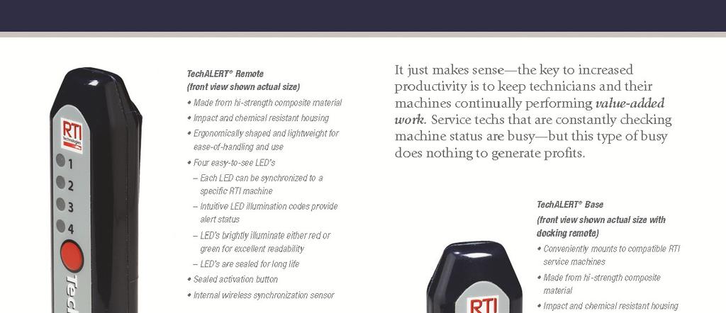
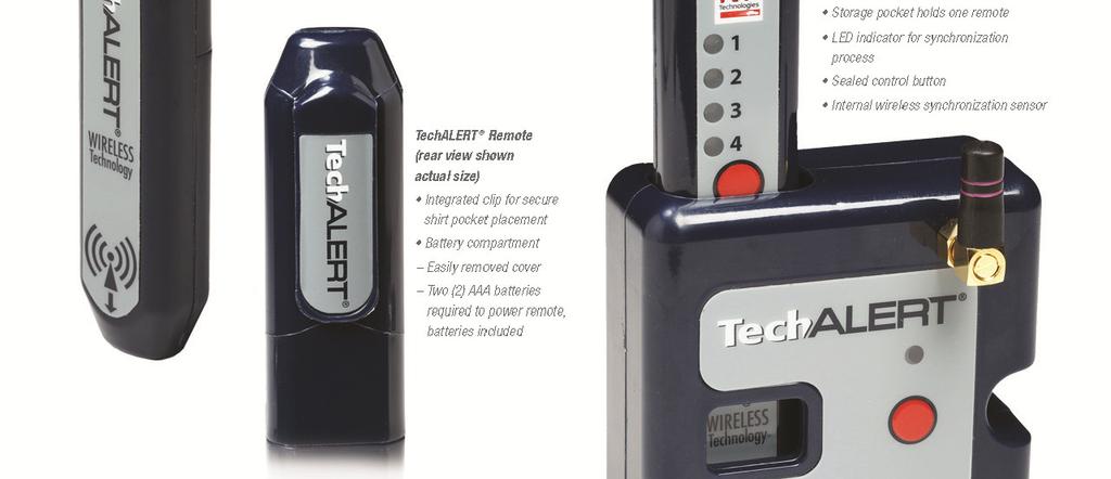
4 Default Values Fill Cylinder Target Amount Initial Vacuum Hold Level Final Vacuum Level Vacuum Run Time Hoses Overcharge Amount Minimum Line Voltage Elevation from Sea Level Vacuum Pump Oil Life Rise Level Oil Drain Maximum Level Minimum Vacuum Leak Level High voltage Flush Maintenance Options Calibration Check Perform Load Cell Site Calibration Perform Load Cell Shop Calibration Perform Vacuum Sensor Calibration Set Date and Time Input/Output Diagnostics Combo Filter Replacement Vacuum Pump Oil Replacement Change Operator Passwords Change Service Manager Password Print Parameters Total Capacities Combo Filter Life Remaining Total Refrigerant Recycled Total Refrigerant Charged Vacuum Pump Oil Life Remaining Reminders TechALERT Demo Mode Vacuum Pump Maintenance Combo Filter Maintenance Inline Filter Maintenance Printer Maintenance Refrigerant Identifier Maintenance Updating Program and Languages Attaching Temperature Probes Frequently Used MAHLE Consumable Items Parts Identification Notes TechALERT


5 INTRODUCTION MAHLE RHS980C Refrigerant Handling System is designed for use on R134a vehicles and is compliant with J2788 standard. Unit recovers 95% of automobile refrigerant systems and has a refrigerant recharge accuracy of +/- ½ ounce. It features fully automatic operation. All control functions of the RHS980C are designed to provide intuitive and rapid interaction with the service technician. Easily removable one piece composite cover allows gaining unobstructed access to all interior components for service and maintenance. Images below show the key features of RHS980C Refrigerant Handling System. Low Side Service Hose with Coupler Control Panel with LCD Display High Pressure Gauge High Side Service Hose with Coupler Low Pressure Gauge Oil Drain Bottle and O-ring Power Switch Removable Cover Fill Cylinder Hose New Refrigerant Storage Shelf Refrigerant Identifier (optional) Rotating Turret TechALERT USB Port Storage Compartments Printer 5
6 OVERVIEW OF THE RHS980C AND HOW TO OPERATE IT The RHS980C is designed for intuitive operation with menu driven prompts on the display. A few minutes spent reviewing the contents of this operation manual will enable the technician to understand and optimize the use of the RHS980C to provide customers with a professional A/C service. The display shows data such as the internal cylinder weight and prompts the technician for input using the alphanumeric keypad and various navigation buttons. The RHS980C can be used to perform a fully automatic A/C service. The technician will be prompted for entry of data such as charge amount and given options like vacuum leak test. Once the necessary data has been entered, the RHS980C will automatically perform the complete A/C service and alert the technician for interaction or that the service is complete. The RHS980C can also be used to perform individual functions like recycle, vacuum or charge. The keypad has dedicated buttons (AUTOMATIC, RECYCLE, VACUUM and CHARGE) to allow the technician to jump directly to any one of these functions. Units of measure displayed can be changed at any time by repeatedly pressing the U/M key. A setup routine can be used to select options, set default values, perform maintenance operations and manage fluid capacities processed. IMPORTANT review the Startup & Safe Operation statements on the following page before operating the RHS980C. Failure to do so may cause personal injury or cause the RHS980C to malfunction. The Automatic Mode of operation is explained in the following pages. The screen which will be displayed for each step is shown on the left. A description of the RHS980C operation is shown to the right of each screen. VERY IMPORTANT MACHINE SHUTDOWN The new SAE Standard J2788 dictates that the filter must be changed at set intervals to ensure that recycled refrigerant is pure. The RHS980C has one filter which must be changed after recycling every 150 lbs. of refrigerant. The technician will be alerted when the filter life is at 100 LB (45 KG). This allows time to order a replacement filter kit (See Parts Identification ). When the filter has purified 150 LB (68 KG) of refrigerant, the RHS980C will shut down and not perform any function. A new filter must be installed to re-activate the RHS980C controller. Fill out and return the Warranty Registration to activate the RHS980C warranty and free lifetime technical support. This can also be done by calling MAHLE and providing information to one of the Technical Support Technicians. Call
7 STARTUP & SAFE OPERATION Do not use a damaged unit. Check for shipping damage and place a claim with carrier if damage is discovered. Return the Warranty Card to activate technical support service and warranty coverage. The RHS980C should be operated by certified personnel only. The RHS980C should not be operated or serviced by any person who has not read all the contents of this manual. This manual describes normal operation and maintenance for the RHS980C. Failure to read and comply with these instructions or any one of the limitations noted herein can result in serious injury and/or property damage. The instructions should not be interpreted to anticipate every possible contingency. It is the responsibility of the owner/user to operate the RHS980C in accordance with all laws and specifications which may apply. Recover, recycle, and charge only R134a. Avoid breathing refrigerant or lubricant vapor. Exposure may irritate eyes, nose and throat. Ventilate work area if accidental system discharge occurs. Wear safety glasses and protective gloves. Refrigerant has a very low boiling point and can cause frostbite. Follow the RHS980C operating procedures sequentially to avoid prematurely disconnecting hoses or opening valves which may release refrigerant to the atmosphere. Do not expose the RHS980C to moisture or operate in wet areas. Use RHS980C in areas with ventilation that provides at least four air changes per hour. Service hoses must be constructed of the proper materials and with lengths as supplied with the RHS980C (See Parts Identification ). Hoses must have shutoff devices at the connection point to the A/C to minimize the introduction of air into the RHS980C and the release of refrigerant when being disconnected. Avoid using an extension cord with the RHS980C. If necessary use a good condition, three wire grounded, #14 AWG or larger extension cord of the shortest possible length. Disconnect power before performing any maintenance or service on the RHS980C. SPECIAL CONSIDERATIONS WITH R134a R134a has been shown to be nonflammable at ambient temperature and atmospheric pressure. However, tests under controlled conditions have indicated that at pressures above atmospheric and with air concentrations greater than 60 percent by volume, R134a can form combustible mixtures. While it is recognized that an ignition source is also required for combustion to occur, the presence of combustible mixtures is a potentially dangerous situation and should be avoided. Under no circumstances should any equipment be pressure tested or leak tested with air and R134a mixtures. Do not use compressed air for leak detection in R134a systems. 7
8 CONTROL PANEL AUTOMATIC RECYCLE VACUUM CHARGE GHI 2 ABC 5 JKL 3 DEF 6 MNO YES START 7 PQRS 8 TUV 9 WXYZ * CLR 0 SPACE # U/M Pressing any one of these four buttons causes the RHS980C to jump to the respective procedure. AUTOMATIC RECYCLE VACUUM CHARGE 1 2 ABC 3 DEF The alpha-numeric keypad is used to enter data when prompted on the LCD screen. 4 GHI 7 PQRS CLR * 5 JKL 8 TUV 0 SPACE 6 MNO 9 WXYZ # U/M Note: The # key also has U/M printed on it. Pressing this key will toggle the units of measure displayed on the LCD screen. Note: Pressing the number 4 key provides quick access to change languages. Follow prompts to select desired language. YES START Pressing any one of the arrow keys will move the point of data entry on the LCD screen in the respective direction. Some screens provide options to select. The arrow keys make it possible to select the desired input. The START and STOP buttons are used to start or stop procedures as prompted on the LCD screen. 8
9 FIRST TIME USE The first time a new RHS980C is powered up it will automatically perform a routine where the language is selected. The language can be changed later if desired in the Setup Mode. The RHS980C will arrive without any refrigerant. It will be necessary to put new refrigerant into the internal charge cylinder before any other sequences can be run. The amount of refrigerant which to be transferred is factory set at 18 LB (8.16 KG). This amount can be adjusted if desired. Refer to SETUP section under DEFAULT VALUES to change the factory setting. Connect the short yellow hose on the rear of the RHS980C to a new 30 lb. cylinder of refrigerant. Open the cylinder valve, turn the cylinder up-sidedown and place it on the platform. Secure with web belt. Plug the power cord into an appropriate power source. Avoid using an extension cord. If necessary, use a good condition, three wire grounded, #14 AWG or larger extension cord of the shortest possible length. M A H L E R H S C A F T E R M A R K E T I N C. # # # # # # Press the Power Switch to turn on the RHS980C. The screen shown to the left will be displayed and a buzzer will sound. S E L E C T L A N G U A G E E N G L I S H E S P A Ñ O L e F R A N Ç A I S D E U T C H, E N T E R P A S S W O R D # # # # S T A R T T O C O N T I N U E P A S S W O R D A C C E P T E D S T A R T T O C O N T I N U E P A S S W O R D R E J E C T E D S T A R T T O R E T R Y Press or key to scroll the displayed arrow to the desired language. Press START key. (Refer to Section CHANGING LANGUAGES for additional information on loading new languages) Note: Pressing the #4 key from the main menu will access the language selection option. If password protection is NOT enabled then the next 3 subsequent screens will not be shown. Enter any of the 11 stored passwords (10 operator and 1 service manager) to gain access to operate the RHS980C. The passwords will prevent non certified technicians from performing A/C service. A service manager password is required to change several machine parameters. See section on Maintenance Options for complete listing of passwords. Press START key to continue. If password is accepted, this screen is shown. Press START key. If password is rejected, this screen is shown. Check the password and press START key to retry the entry or press STOP key to end. A U T O M A T I C The screen shown to the left will be displayed. Press the key to scroll to the next screen. R E C Y C L E Press key. V A C U U M Press key. 9
10 C H A R G E F I L L C Y L I N D E R S T A R T I N G R E F R I G E R A N T I D E N T I F I E R D O N O T C O N N E C T H O S E S P L E A S E W A I T... E X A M I N E I D S A M P L E H O S E / F I L T E R F O R O I L S T A R T T O C O N T I N U E Press key. Press START key. If the internal cylinder capacity is equal to or greater than the target amount shown in DEFAULT VALUES, the FILL CYLINDER process will not be available from the main menu. If the RHS980C has a refrigerant identifier installed, the screen to the left and next 3 subsequent screens will appear. The refrigerant identifier is an optional item and can be installed in the field. Contact MAHLE for more information. Inspect the identifier hose for traces of oil contamination. If oil is present in the hose, remove the contaminated hose section or replace the entire hose assembly. See REFRIGERANT IDENTIFIER MAINTENANCE section of manual. Press START key. C O N N E C T I D E N T I F I E R S A M P L E H O S E T O L O W S I D E P R E S S Y E S W H E N D O N E G A S A N A L Y S I S I S I N P R O C E S S.. P L E A S E W A I T Connect refrigerant identifier hose found on the rear of the RHS980C to the cylinder of new refrigerant. Unit includes an adapter to convert the ½ inch Acme fitting on the cylinder to low side coupler. Cylinder of new refrigerant must be upright with valve at top of tank. Press YES key. R E M O V E I D E N T I F I E R S A M P L E H O S E F R O M L O W S I D E P R E S S Y E S W H E N D O N E I D R E S U L T S : R : # #. # %, A I R : # #. # % H C : # #. # % P R E S S N O T O R E J E C T, Y E S T O A C C E P T > 5 % A I R S U G G E S T S E X C E S S O I L I N S A M P L E H O S E / F I L T E R. R E M E D Y B E F O R E U S E. C O N N E C T H O S E T O S O U R C E T A N K O P E N V A L V E Sample of new cylinder refrigerant is processed and the hose and coupler must be removed. Press START key. This shows the results from the identifier refrigerant sample processed. Select NO key to reject these results or YES key to accept the results. Pressing NO will return to the initial screen. If the results from the refrigerant identification show an air percentage above 5%, this screen will appear. Inspect the id filter, sample hose and coupler filter prior to the next identification to ensure these devices are free of oil contamination. See REFRIGERANT IDENTIFIER MAINTENANCE section for more information. This is a reminder that the cylinder of new refrigerant must be connected to the yellow hose on the rear of the RHS980C. Press START key. F I L L C Y L I N P R O C E S S A M T F I L L E D # #. # L B Refrigerant will be transferred from the cylinder on the rear platform into the internal charge cylinder of the RHS980C. Cylinder of new refrigerant must be upside down with valve at bottom of tank. 10
11 F I L L C Y L I N P R O C E S S T I M E L E F T # #. # # F I L L C Y L C O M P L E T E A M T F I L L E D # #. # L B The amount transferred will be displayed. Note: Pressing the STOP key will start an internal clearing process. This process must run to completion to remove internal refrigerant. The Fill Cylinder procedure is complete when desired amount of refrigerant has been transferred. The Setup procedure allows changing the value and is covered in DEFAULT VALUES section in this manual. Note: To fill to less than 18 LB (8.16 KG), close valve on cylinder of new refrigerant and allow procedure to complete. A minimum of 10 LB (4.53 KG) is suggested for truck service application. REFRIGERANT BLENDS The RHS980C is designed to recover, recycle and charge R134a. Take extreme precaution to ensure that other refrigerants are not recovered into the RHS980C. A refrigerant identifier is recommended for evaluating refrigerant in the A/C system prior to servicing. Recovering other refrigerants will contaminate the refrigerant in the RHS980C charge cylinder. LEAK SEALERS Sealants and leak stop chemicals in A/C systems may cause serious damage to the RHS980C if they are present in the refrigerant recovered intended for recovery. Detection devices are readily available to check for the presence of these chemicals and are highly recommended to protect the RHS980C. Call MAHLE for more information about solutions for detection of refrigerant blends and leak sealers. AUTOMATIC OPERATION A U T O M A T I C At the main menu screen, press the START key. S T A R T I N G R E F R I G E R A N T I D E N T I F I E R D O N O T C O N N E C T H O S E S P L E A S E W A I T... If the RHS980C has the optional refrigerant identifier installed, the screen to the left and next 6 subsequent screens will appear. E X A M I N E I D S A M P L E H O S E / F I L T E R F O R O I L S T A R T T O C O N T I N U E C O N N E C T I D E N T I F I E R S A M P L E H O S E T O L O W S I D E P R E S S Y E S W H E N D O N E Inspect the identifier hose for traces of oil contamination. If oil is present in the hose, remove the contaminated hose section or replace the entire hose assembly. See REFRIGERANT IDENTIFIER MAINTENANCE section of manual. Press START key. Connect refrigerant identifier hose found on the rear of the RHS980C to the vehicle low side service port. Press YES key. G A S A N A L Y S I S I S I N P R O C E S S.. P L E A S E W A I T 11
12 R E M O V E I D E N T I F I E R S A M P L E H O S E F R O M L O W S I D E P R E S S Y E S W H E N D O N E I D R E S U L T S : R : # #. # %, A I R : # #. # % H C : # #. # % P R E S S N O T O R E J E C T, Y E S T O A C C E P T > 5 % A I R S U G G E S T S E X C E S S O I L I N S A M P L E H O S E / F I L T E R. R E M E D Y B E F O R E U S E. C H E C K O I L D R A I N L E V E L, A D J U S T O R I N G T O T O P O F L E V E L S E L E C T V A C U U M T Y P E E N H A N C E D S T A N D A R D E N T E R V A C U U M T I M E # # M I N U S E A C C A P A C I T Y G U I D E T O D E T E R M I N E C H A R G E A M O U N T? S E L E C T Y E S O R N O Sample of vehicle A/C refrigerant is processed and the hose and coupler must be removed. Press START key. This shows the results from the identifier refrigerant sample processed. Select NO key to reject these results or YES key to accept the results. Pressing NO will return to the initial screen. A high air percentage can be an indication of required maintenance, see Identifier Maintenance section for more information. If the results from the refrigerant identification show an air percentage above 5%, this screen will appear. Inspect the id filter, sample hose and coupler filter prior to the next identification to ensure these devices are free of oil contamination. See REFRIGERANT IDENTIFIER MAINTENANCE section for more information. Ensure that the oil drain bottle has enough remaining capacity to perform a service. Adjust the o-ring slider so it is level with the oil in the oil drain bottle. Press START key. Select vacuum type, Enhanced or Standard. If enhanced is selected, the unit will draw a deeper vacuum and use the onboard micron sensor. The enhanced vacuum process will take longer than the standard vacuum process. The standard procedure will utilize a pressure transducer to measure vacuum levels. Press START key. Enter the time desired to vacuum the A/C system. Press START key. See SETUP SELECTABLE OPTIONS to enable or disable AC Capacity Guide. To use the on board AC capacity guide to determine the charge amount for the vehicle, press YES key. Otherwise press NO key. Pressing the YES key will show the next 9 subsequent screens. U S E T O S C R O L L P A G E U P & D O W N S T A R T T O C O N T I N U E Screen shows the instructions for the navigation and selection of the information shown on the next 5 screens. Press YES key to continue or NO key to abort operation. V E R I F Y I N G D A T A B A S E Screen to the left will appear after operator selections are made and data is processed internally. P L E A S E W A I T... S E L E C T > # # # # > # # # # > # # # # Y E A R Select the year for the vehicle being serviced. Press YES key on the highlighted value to continue. Use or key to scroll the displayed arrow to the desired selection. S E L E C T M A K E > # # # # # # # > # # # # # # # > # # # # # # # Select the make of the vehicle being serviced. Press YES key on the highlighted value to continue. Use or key to scroll the displayed arrow to the desired selection. 12
13 S E L E C T M O D E L > # # # # # # # > # # # # # # # > # # # # # # # Select the model of the vehicle being serviced. Press YES key on the highlighted value to continue. Use or key to scroll the displayed arrow to the desired selection. S E L E C T E N G I N E > # # # # # # # > # # # # # # # > # # # # # # # Select the engine configuration of the vehicle being serviced, if more than 1 option is available. Press YES key on the highlighted value to continue. Use or key to scroll the displayed arrow to the desired selection. S E L E C T S Y S T E M > # # # # > # # # # > # # # # If required, a screen to select the system for the vehicle being serviced will be shown. Press YES key on the highlighted value to continue. Use or key to scroll the displayed arrow to the desired selection. Y E A R, M O D E L, E N G I N E S Y S T E M, T Y P E X X, X X O Z C O N D E N,, S E R C A P A C I T Y X X O Z O I L T Y P E # # # # # T O T A L O I L C A P A C I T Y # ## # # # O Z E N T E R C H A R G E A M O U N T # #. # L B C U R R E N T O I L T Y P E P A G / P O E < > T O C H A N G E The data will be shown for the vehicle parameters entered on this screen. Year, make, model, type, system and refrigerant capacity in OZ is detailed. Press key to display the next screen or YES key to accept the charge amount. The oil type and total oil capacity are shown on the screen for the selected vehicle parameters. Press key to display the previous screen or YES key to accept the charge amount. Enter the amount of refrigerant to be charged into the A/C system or the charge capacity will be automatically entered if the AC database was used. Press START key. Press or key to change the type of oil which exists on the A/C system being serviced. A HIGH VOLTAGE OIL FLUSH will be started automatically if the type is changed. S E L E C T T O C H A R G E H I G H / L O W / B O T H C O N N E C T H O S E S O C P E N V A L V E S C L E A R I N G I N P R O C E S S P L E A S E W A I T Press or key to select which side to charge to on the A/C system. The word HIGH, LOW or BOTH will display in bold letters. Note: If oil injection was selected, only HIGH or BOTH will be enabled. Press START key. Connect the red hose to the high side and the blue hose to the low side of the A/C system. Open the valves on both hoses. Press START key. A clearing procedure will run to remove refrigerant from internal components. R E C Y C L E I N P R O C E S S A M T R E C # #. # L B The RHS980C will now recover and recycle refrigerant. The amount of refrigerant recovered will be displayed. The next screen will be displayed when vehicle system pressure is in a vacuum. 13
14 O I L D R A I N I N P R O C E S S P L E A S E W A I T When the vehicle system reaches 10 psi, the machine will drain any recovered oil. R E C Y C L E I N P R O C E S S A M T R E C # #. # L B T I M E L E F T # # M I N V A C U U M I N P R O C E S S T I M E L E F T # # M I N L E V E L # # # # # M I C R O N C H E C K I N G V A C U U M L E A K T I M E L E F T # # S E C L E V E L # # # # # M I C R O N The RHS980C will continue to recycle refrigerant and complete after the time shown is expired. The RHS980C will draw a deep vacuum on the A/C system for the time entered in the default vacuum run time in the set up menus. The time left and the vacuum level in micron will be displayed if Enhanced vacuum is selected. The vacuum leak test will begin. The time left and the micron level will be displayed if Enhanced vacuum is selected. If the vacuum level rises above leak level set in set up default menu, an error screen will be displayed. V A C U U M I N P R O C E S S T I M E L E F T # # M I N L E V E L # # # # # M I C R O N P U R G E I N P R O C E S S P L E A S E W A I T A second deep vacuum process will run for the length of time displayed. The RHS980C will purge air from the recovered refrigerant if necessary. This process will be displayed. C L E A R I N G I N P R O C E S S P L E A S E W A I T C H A R G E I N P R O C E S S A M T C H G = # #. # L B D O N O T D I S T U R B U N I T! A U T O M A T I C C O M P L E T E A M T R E C # #. # L B A M T C H G # #. # L B A clearing procedure will run to remove refrigerant from internal components. The RHS980C will charge the amount of refrigerant set previously into the A/C system. TO AVOID AN INACCURATE CHARGE, DO NOT BUMP OR MOVE THE RHS980C DURING THIS PROCESS. The automatic cycle is complete when the desired amount of refrigerant has been charged. The amount of refrigerant recycled and the amount of refrigerant charged will be displayed. Press START key. S T A R T T O E V A C H O S E S S T O P T O T E S T M O D E Press START key to proceed to the hose evacuation procedure as outlined below. Press STOP key to perform AC system test mode. See A/C SYSTEM TEST MODE for a description of this feature. 14
15 D I S C O N N E C T H S H O S E A N D S T A R T A / C M A X Close the high side coupler and disconnect from the vehicle system coupler. Start the engine and place the A/C system on max setting. Press START key. E Q U A L I Z I N G P L E A S E W A I T H O S E S While the engine and A/C system is running, liquid is being removed from the services hoses. This ensures only vapor remains in hoses. D I S C O N N E C T L O W S I D E H O S E, S H U T O F F E N G I N E Close the low side coupler and disconnect from the vehicle system coupler. Turn off the vehicle engine. Press START key. C L E A R I N G I N P R O C E S S P L E A S E W A I T A clearing procedure will run to remove refrigerant from internal components. C L E A R I N G H O S E S A M T R E C # #. # L B T I M E L E F T # # M I N E V A C H O S E S C O M P L E T E I N S T A L L S E R V I C E C A P S A D D O I L I F R E Q U I R E D Any vapor refrigerant remaining in the hoses will be recovered into the RHS980C. The automatic cycle is complete when the hose evacuation process is ended. Check the level of oil drained and add oil to the A/C system following standard injection procedures. Reinstall service caps onto vehicle A/C ports. 15
16 A/C SYSTEM TEST MODE A U T O M A T I C At the main menu screen, press the key 7 times. Press START key. A / C S Y S T E M T E S T M O D E S T A R T I N G R E F R I G E R A N T I D E N T I F I E R D O N O T C O N N E C T H O S E S P L E A S E W A I T... If the RHS980C has the optional refrigerant identifier installed, the screen to the left and next 6 subsequent screens will appear. E X A M I N E I D S A M P L E H O S E / F I L T E R F O R O I L S T A R T T O C O N T I N U E C O N N E C T I D E N T I F I E R S A M P L E H O S E T O L O W S I D E P R E S S Y E S W H E N D O N E Inspect the identifier hose for traces of oil contamination. If oil is present in the hose, remove the contaminated hose section or replace the entire hose assembly. See REFRIGERANT IDENTIFIER MAINTENANCE section of manual. Press START key. Connect refrigerant identifier hose found on the rear of the RHS980C to the vehicle low side service port. Press YES key. G A S A N A L Y S I S I S I N P R O C E S S.. P L E A S E W A I T R E M O V E I D E N T I F I E R S A M P L E H O S E F R O M L O W S I D E P R E S S Y E S W H E N D O N E I D R E S U L T S : R : # #. # %, A I R : # #. # % H C : # #. # % P R E S S N O T O R E J E C T, Y E S T O A C C E P T > 5 % A I R S U G G E S T S E X C E S S O I L I N S A M P L E H O S E / F I L T E R. R E M E D Y B E F O R E U S E. C O N N E C T H O S E S O P E N V A L V E S Sample of vehicle A/C refrigerant is processed and the hose and coupler must be removed. Press START key. This shows the results from the identifier refrigerant sample processed. Select NO key to reject these results or YES key to accept the results. Pressing NO will return to the initial screen. A high air percentage can be an indication of required maintenance, see Identifier Maintenance section for more information. If the results from the refrigerant identification show an air percentage above 5%, this screen will appear. Inspect the id filter, sample hose and coupler filter prior to the next identification to ensure these devices are free of oil contamination. See REFRIGERANT IDENTIFIER MAINTENANCE section for more information. Connect the red hose to the high side and the blue hose to the low side of the A/C system. Open the valves on both hoses. Press START key. 16
17 P R E C H A R G I N G H O S E S A M T C H G = # #. # L B D O N O T D I S T U R B U N I T! The RHS980C will precharge the hoses with refrigerant. Allow unit to automatically proceed to the next step. Press STOP key will abort operation. A T T A C H T E M P P R O B E S T O V E H I C L E A N D S T A R T E N G I N E W I T H A / C M A X T 1 = # # # T 2 = # # # T 3 = # # # H I G H P R E S = # # # R H = # # # L O W P R E S = # # # * T O C L R S T A R T T O C A P T U R E T1, T2 and T3 are external temperature probes attached to the rear of unit. Attach temperature probes to vehicle following the service manual vehicle performance test procedures. Start vehicle engine with the A/C system on maximum. Press START key. The RHS980C will start displaying A/C performance data. Units of measure can be changed by pressing the U/M key. The lowest temperature is tracked and updated on the LCD screen. The highest pressure is tracked and updated. The lowest pressure is tracked and updated. RH is the relative humidity. Press the * key to refresh or reset the tracking of data. Press the START key to capture the data and proceed to the next step. P R I N T R E S U L T S? S T A R T T O C O N T I N U E Press START key to print performance results captured. Press STOP key to end. Refer to PRINTING RESULTS section of manual for details on printing. E N T E R V I N N U M B E R # # # # # # # # # # # # # # # # # S T A R T T O C O N T I N U E P R I N T I N G R E S U L T S T O P R I N T E R P L E A S E W A I T... Using the alpha-numeric keypad, enter the vehicle identification number. Follow typical text messaging methods to enter characters. After a brief delay during entry, cursor position will move to the right. Press START key when complete. Screen to left will be shown when data is printing. C L E A R R E S U L T S / D A T A C O L L E C T E D? S E L E C T Y E S O R N O Press YES key if printing is complete or NO key if another copy is required. T E S T M O D E C O M P L E T E S T A R T T O E V A C H O S E S Press START key to begin hose evacuation procedure. W I T H E N G I N E R U N N I N G A N D A / C M A X D I S C O N N E C T H S H O S E Disconnect high side coupler from vehicle with the engine running and A/C system on maximum. Press START key to continue. 17
18 E Q U A L I Z I N G P L E A S E W A I T H O S E S While the engine and A/C system is running, liquid is being removed from the services hoses. This ensures only vapor remains in hoses. D I S C O N N E C T L O W S I D E H O S E, S H U T O F F E N G I N E Close the low side coupler and disconnect from the vehicle system coupler. Turn off the vehicle engine. Press START key. C L E A R I N G I N P R O C E S S P L E A S E W A I T A clearing procedure will run to remove refrigerant from internal components. C L E A R I N G H O S E S A M T R E C # #. # L B T I M E L E F T # # M I N Any vapor refrigerant remaining in the hoses will be recovered into the RHS980C. E V A C H O S E S C O M P L E T E I N S T A L L S E R V I C E C A P S A D D O I L R E Q U I CE R E D The A/C system test mode is complete when the hose evacuation process is ended. Check the level of oil drained and add oil to the A/C system following standard injection procedures. Reinstall service caps onto vehicle A/C ports. 18

19 PRINTING RESULTS A U T O M A T I C At the main menu screen, press the key 5 times. See Printer Maintenance section if additional paper is required. P R I N T R E S U L T S Press START key. E N T E R V I N N U M B E R # # # # # # # # # # # # # # # # # S T A R T T O C O N T I N U E P R I N T I N G R E S U L T S T O P R I N T E R P L E A S E W A I T... Using the alpha-numeric keypad, enter the vehicle identification number. Follow typical text messaging methods to enter characters. After a brief delay during entry, cursor position will move to the right. Press START key when complete. Screen to left will be shown when data is printing. C L E A R R E S U L T S / D A T A C O L L E C T E D? S E L E C T Y E S O R N O Example of printout: Press YES key if printing is complete or NO key if another copy is required. Printout will scroll from the rear of the machine. Pull paper at a slight angle upright to remove. See picture below. * * * * * * * * * * * * * * * * * * * * * * M A H L E A F T E R M A R K E T I N C. R H S C D A T E : # # - # # - # # # # T I M E : # # : # # S O F T W A R E R E V : C # # P R I N T O U T OF F R E S U L T S V I N : # # # # # # # # # # # # # # # # # A M B I E N T D A T A R E L A T I V E H U M I D I T Y : # # % T E M P E R A T U R E : # # # F V E H I C L E D A T A T 1 T E M P M I N : # # # F T 2 T E M P M I N : # # # F T 3 T E M P M I N : # # # F H I G H S I D E M A X P R E S : # # # P S I L O W S I D E M I N P R E S : # # # P S I R E C Y C L E D : # #. # L B S V A C L E A K T E S T : # # # # # # M I N V A C : # # # # M I C R O N C H A R G E D : # #. # L B S * * * * * * * * * * * * * * * * * * * * * * Units of measure on print-out are dependent on selected units during normal operation. Depending on the process performed, selected data will be available for printing. Data is stored when the processes are allowed to run until full completion. 19
20 HIGH PRESSURE LEAK DETECT HIGH PRESSURE LEAK DETECT allows an operator to pressurize a component or system to detect a difficult to locate leak prior to checking with an external leak detector. Recommend to start process with an internal system capacity of 8 to 10 LB (3.63 to 4.54 KG). Use of a leak detector meeting newest standard SAE J2791 or later is suggested. A U T O M A T I C At the main menu screen, press the key 4 times. H I G H P R E S S U R E L E A K D E T E C T Press START key. E N T E R F I N A L T A R G E T P R E S S U R E # # # P S I B E T W E E N 7 0 & P S I Using the alphanumeric keypad, enter the final target pressure for the system or component under test. Recommend a setting of 90 PSI for most applications. Press START key to continue. I N T E R N A L B U I L D I N G C Y L I N D E R P R E S S U R E P L E A S E W A I T The RHS980C will begin building internal pressure to the specified target amount. H I G H P R E S S U R E L E A K F A I L E D, U N A B L E T O R E A C H T A R G E T, S E E M A N U A L C H A R G E I N P R O C E S S A M T C H G = # #. # L B D O N O T D I S T U R B U N I T! H P L E A K D E T E C T D O N E P E R F O R M L E A K C H E C K U S I N G E X T E R N A L L E A K D E T E C T O R If the unit has failed to build the desired pressure after 30 minutes, the screen to left is displayed. Add refrigerant to the internal cylinder and retry procedure. Press START key to continue. After reaching the target pressure, the unit will charge the system or component with liquid refrigerant. Press the STOP key to abort the operation. When charge is complete, the screen shown will appear. Check for system leaks using a leak detector. Refrigerant must be recovered after leak check is completed. WARNING DO NOT START VEHICLE AC SYSTEM IF HIGH PRESSURE LEAK DETECT PROCEDURE WAS USED. COMPRESSOR DAMAGE COULD RESULT. A RECYCLE PROCEDURE MUST FOLLOW LEAK DETECT. 20
21 HIGH VOLTAGE OIL FLUSH The RHS980C can be configured from the factory to have the ability to perform an internal oil flushing process to eliminate cross contaminations between PAG oil used in a conventional R-134a system and POE oil used in HIGH VOLTAGE HYBRID systems. The POE oil acts as a lubricant, but more importantly the POE oil is required to keep the HIGH VOLTAGE system isolated from the chassis. If the HYBRID s system becomes conductive, the service technician can be at risk of electrical shock. During the HIGH VOLTAGE OIL FLUSH process the residual PAG oil from previous services will be flushed from the HIGH - low side couplers and hoses along with the corresponding internal passages of the RHS980C unit. IMPORTANT THE HIGH VOLTAGE OIL FLUSH PROCESS MUST BE PERFORMED BEFORE A SERVICE ON A HYBRID VEHICLE WITH THIS MACHINE IS CONDUCTED! IT IS THE SERVICE TECHNICIANS RESPONSIBILITY TO UNDERSTAND THE RISKS INVOLVED IN SERVICING A HIGH VOLTAGE HYBRID A/C SYSTEM, AS WELL AS DETERMING THE PROPER OIL REQUIRED FOR THE HYBRIDS A/C SYSTEM TO ENSURE ITS ELECTRICAL ISOLATION FROM THE VEHICLES CHASSIS IS MAINTAINED. With units configured for the High Voltage Oil Flush there will be a screen illustrated below that will start the High Voltage Oil Flush process. The manual oil injection bottle and connections will NOT be present next to the oil drain bottle. The High Voltage Oil Flush configured unit will also be shipped with a HIGH -LOW side adapter so that the hoses can be connected to flush residual oil from previous services. To get to the HIGH VOLTAGE OIL FLUSH FEATURE, follow the procedure below. A U T O M A T I C The screen shown to the left will be displayed. Press the key to scroll to the next screen. Press key. R E C Y C L E Press key. V A C U U M Press key. C H A R G E F I L L C Y L I N D E R Press key. 21


22 T E C H A L E R T D E M O Press key. H I G H V O L T A G E O I L F L U S H C O N N E C T E X T F L U S H A D A P T E R T O L O W A N D H G I G H S I D E C O U P L E R S Press START key. Connect the HIGH and LOW side couplers with the supplied HIGH VOLTAGE OIL FLUSH adapter as shown below, open HIGH and LOW side couplers. Press the START key. C H A R G E I N P R O C E S S HA Rg M T C H G = # #. # # L B D O N O T D I S T U R B U N I T! S T O P T OT E N D The RHS980C will perform the HIGH VOLTAGE OIL FLUSH process at this time. R E C Y C L E I N P R O C E S S C A M T R E C # #. # # L B T I M E L E F T # # : # # H I G H V O L T A G E O I L F L U S S H C O M P L E T E Press STOP key to end the process, disconnect the HIGH and LOW service couplers from the adapter. 22
23 REFRIGERANT FLUSH REFRIGERANT FLUSH will force liquid refrigerant in a reverse flow through a component or components to remove contaminates and oil. Special flush components and adapters are available through MAHLE to properly connect to standard AC components. W A U T O M A T I C At the main menu screen, press the key 1 time. R E F R I G E R A N T F L U S H Press START key. E N T E R T I M E F O R F L U S H # # M I N B E T W E E N 5 A N D 3 0 M I N Enter the desired time to flush using the alphanumeric keypad. Press START key to continue. C H E C K O I L D R A I N L E V E L, A D J U S T O R I N G T O T O P O F L E V E L Empty oil bottle and adjust o-ring. Press START key to continue. C H E C K I N G P R E S S U R E S P L E A S E W A I T C O N N E C T F L U S H F I L T E R T O L O W S I D E A N D C O U P L E R S T O S Y S T E M F L U S H I N P R O C E S S T I M E L E F T ~ # # : # # Following adapter detailed installation instructions, connect flush filter and service couplers to AC component. Press START key to continue. The RHS980C will pulse charge liquid and recycle refrigerant through the component being serviced. Contaminants will be captured in the service filter. Press the STOP key to abort the operation. F L U S H C O M P L E T E D I S C O N N E C T C O U P L E R S A N D F L U S H F I L T E R C H E C K O I L B O T T L E C L E A N F L U S H F I L T E R Observe pressure shown on pressure gauges and if pressure is less than 0 psi, carefully remove connections from component under test. If pressure is greater than 0 psi, perform a recycle before disconnecting component. Press START key to continue. Check the oil bottle and empty if required. Flush filter must be replaced after every service. Press START key to continue. If system states CHARGE FAILED, check flush filter, component or system for blockage. Replace as required. Filter: Since refrigerant flushing removes all oil from the component being serviced, ensure that the proper quantity of oil is manually replenished. 23
24 SETUP The setup procedure provides a means of setting options for various operation functions of the RHS980C. A U T O M A T I C The initial screen displayed after turning on power will be as shown to the left. S E T U P Press the key to scroll through screens until the setup screen shown to the left is displayed. Press the START key. SELECTABLE OPTIONS S E L E C T A B L E O P T I O N S The first screen will be for SELECTABLE OPTIONS. Press the key to scroll through other setup screens: DEFAULT VALUES, MAINTENANCE OPTIONS and TOTAL CAPACITIES. These four setup procedures are described below. Press START key. S E L E C T L A N G U A G E E N G L I S H E S P A Ñ O L e F R A N Ç A I S, Default is ENGLISH. B U Z Z E R E N A B L E D? Y E S N O Default is YES. The first option is to select the language which is used on LCD display screens. Press or key to scroll the displayed arrow to the desired language. Press START key. Note: Pressing the #4 key from the main menu will access the language selection option. This enables or disables the buzzer on the RHS980C. Press the or key to scroll to YES or NO. Press START key. R E F R I G I D I N S T A L L E D? Y E S N O Default is NO. This enables the RHS980C to interact with the MAHLE Refrigerant Identifier. If this optional item was not installed at the factory, visit the MAHLE web-site for more information. Press the or key to scroll to YES or NO. Press START key. A C C A P D B I N S T A L L E D? N O I N T E R N A L E X T E R N A L Default is NO. This enables the RHS980C to interact with the MAHLE Refrigerant Capacity Database. If NO is selected, the operator will not be prompted prior to charge to access the AC Capacity Database for the vehicle charge amount. Selecting external and having flash drive with the optional Database attached to the unit USB port, charge capacities will be available. Selection of internal is not available on RHS980C, Press the or key to scroll to choices. Press START key. Contact MAHLE for more information 24
25 P R I N T E R I N S T A L L E D? Y E S N O Default is YES. P R I N T T O F L A S H D R I V E Y E S N O Default is YES. Use to enable or disable the on board printer on the RHS980C. Press the or key to scroll to YES or NO. Press START key. Use to enable or disable printing service results or setup parameters as files on the attached flash drive. Press the or key to scroll to YES or NO. Press START key. L O W V O L T A G E D E T E C T E N A B L E D? Y E S N O Default is YES. Use to enable or disable the Low Voltage Detect on the RHS980C. Press the or key to scroll to YES or NO. Press START key. M I C R O N V A C U U M S L E W N S O V O R E N A B L E D? Y E S N O Default is YES. P A S S W O R D P R O T E C T I O N E N A B L E D?? N Y E S N O Default is YES. Use to enable or disable the Micron Vacuum Sensor on the RHS980C. Press the or key to scroll to YES or NO. Press START key. This feature can be enabled on the base RHS980C-NAV. IMPORTANT The manager password will also be required to make any changes in the Selectable Options and the Default Values sections if enabled. See Maintenance Options in regards to default password and changing passwords. Press START key. If NO is selected the following screen will be shown. E N T E R P A S S W O R D # # # # S T A R T T O C O N T I N U E Default Service Managers password is 5237, enter this password to continue. Proceed to Maintenance Section to see how to change default password to one of the 20 optional passwords. Press START key. S T A R T U P E N A B L E D? Y E S N O Default is YES. P A S S W O R D An operator password will be required to proceed with any operation after powering the unit if this feature has been enabled. V I N E N T R Y E N A B L E D? Y E S N O Default is YES. O P E R A T O R I D E N T R Y Y E S N O Default is NO. A C T E S T M O D E E N A B L E D? N Y E S N O Default is YES. This feature allows the vehicles VIN to be entered that is being serviced. Press START key. Use to enable or disable the Operator ID Entry feature on the RHS980C. Press the or key to scroll to YES or NO. Press START key. Use to enable or disable the AC Test Mode feature on the RHS980C. Press the or key to scroll to YES or NO. Press START key. 25
26 V A C U U M P U M P O I L L I F E T C E S T E N A B L E D? Y E S N O Default is YES. Use to enable or disable the Vacuum Pump Oil Life feature on the RHS980C. Press the or key to scroll to YES or NO. Press START key. R E F R I G E R A N T L I Q U I D F L U S H E N A B L E D? Y E S N O Default is YES. Use to enable or disable the Refrigerant Liquid Flush feature on the RHS980C. Press the or key to scroll to YES or NO. Press START key. T E C H A L E R T E N A B L E D? Y E S N O Default is YES. D E M O M O D E Use to enable or disable the TechALERT demo mode feature on the RHS980C. Press the or key to scroll to YES or NO. Press START key. H I G H P R E S S U R E L E A K D E T E C T E N A B L E D? Y E S N O Default is YES. Use to enable or disable the High Pressure Leak Detect feature on the RHS980C. Press the or key to scroll to YES or NO. Press START key. A U T O M A T I C W E I G H I N G O I L I N J E C T E N A B L E D? Y E S N O Default is NO. This feature is currently not applicable to the base RHS980C. Enabling this feature will compromise the functionality of the unit. Press START key. A U T O M A T I C W E I G H I N G O I L D R A I N E N A B L E D? Y E S N O Default is NO. This feature is currently not applicable to the base RHS980C. Enabling this feature will compromise the functionality of the unit. Press START key. A U T O M A T I C W E I G H I N G U V D Y E E N A B L E D? Y E S N O Default is NO. H I G H V O L T A G E O I L F L U S H E N A B L E D? Y E S N O Default is YES for RHS 980C This feature is currently not applicable to the base RHS980C. Enabling this feature will compromise the functionality of the unit. Press START key. Use to enable or disable the High Voltage Oil Flush feature on the RHS980C. Press the or key to scroll to YES or NO. Press START key. WARNING DO NOT ENABLE THIS FEATURE IF YOUR UNIT IS NOT CONFIGURED FOR HIGH VOLTAGE OIL FLUSH. IF YOUR UNIT HAS AN OIL INJECTION BOTTLE AND CONNECTION POINT TO INJECT OIL INTO THE A/C SYSTEM DO NOT ENABLE THIS FEATURE. Press START key. 26
27 F I L L C Y L I N D E R E N A B L E D? Y E S N O Default is YES. This feature allows the operator to fill the internal cylinder of the RHS980 from an external virgin refrigerant tank to the preset amount, see Default Values. Press START key. M A N U A L O I L I N J E C T I O N E N A B L E D? Y E S N O Default is NO. This feature is currently not applicable to the base RHS980C, due to this unit being configured to perform a high voltage oil flush function. Enabling this feature will compromise the functionality of the unit. Press START key. 27
28 DEFAULT VALUES D E F A U L T V A L U E S Press START key. F I L L C Y L I N D E R T A R G E T A M O U N T # #. # # L B B E T W E E N 6. 6 & L B I N I T I A L V A C U U M H O L D # # # # # M I C R O N B E T W E E N 3 K & 9 K The Fill Cylinder procedure will automatically transfer refrigerant from a new cylinder of refrigerant to the internal RHS980C charge cylinder. The value set here will be the amount of refrigerant which will have been transferred when the procedure stops automatically. Enter an amount between 3 and 11 KG (6.6 and 24.2 LB). The value will be displayed as it is entered. Press START key. (Default is 8.00 KG (17.6 LB)) The A/C system will be checked for leaks during the vacuum process. This test will pull the A/C system into a vacuum and then pause for a period of 60 seconds. If the vacuum level decreases, it s an indication that the A/C system has a leak. Enter an amount between 3000 and 9000 micron of vacuum. The value will be displayed as it is entered. Press START key. (Default is 5000 MICRON) F I N A L V A C U U M L E V E L # # # # # M I C R O N B E T W E E N 1 K & 9 K This screen allows the adjustment of the final vacuum micron level check performed. After the vacuum procedure is completed, the level achieved must be at least this value or a failure message is displayed. Press START key. (Default is 2000 MICRON) V A C U U M R U N T I M E # C # M I N B E T W E E N 1 & 9 9 M I N H O S E S O V E R C H A R G E A M O U N T #. # # K G B E T W E E N 0 & K G This screen prompts for the length of time the vacuum pump will run during each cycle. There is one initial cycle to pull the system for an initial vacuum leak test, then a second cycle to obtain the final micron level. Enter a number of minutes between 1 and 99. The value will be displayed as it is entered. Press START key. (Default is 10 MIN) A small overcharge of refrigerant is necessary to compensate for refrigerant which will remain in the hose after a charge procedure. Enter the number of KG between 0 and 0.99 (0 and 2.2 LB). The value will be displayed as it is entered. Press START key. (Default is 0.02 KG (0.04 LB)) D E F A U L T M I N I M U M L I N E V O L T A G E # # # V A C B E T W E E N 9 0 & V A C E L E V A T I O N F R O M S E A L E V E L # # # # # F T B E T W E E N 0 & 3 0 K F E E T S During machine operation, the line voltage is monitored to remain above a threshold to ensure correct operation. Enter number of volts between 90 and 120VAC. The value will be displayed as it is entered. Press START key. (Default is 90 V AC) Elevation from sea level to adjust pressure transducer calibration. Enter a number in feet from 0 to 30,000 feet. The elevation can be obtained by calling your local airport. (Default is 400 FT) 28
29 O I L L I F E V A C U U M R I S E L E V E L # # # MI I C R O N B E T W E E N 2 5 i & Enter the amount of rise in vacuum level used during the vacuum pump oil life test. The value must be between 25 and 200 micron. Press START key. (Default is 50 micron) O I L D R A I N M A X L E V E L # # # M L B E T W E E N 5 0 & M L This feature is currently not applicable to the base RHS980C. Enabling this feature will compromise the functionality of the unit. Press START key. M I N I M U M V A C U U M L E A K L E V E L # # I N H G B E T W E E N 1 5 & 2 5 I N H G H I G H V O L T A G E F L U S H C H G A M T 1. 6 L B B E T W S E E N 0. 1 & 2. 0 L B During vacuum leak test, this value is used to determine a pass or fail. (Default is 29 in hg) The Default value is 1.6 lbs for the HIGH VOLTAGE OIL FLUSH. WARNING, DO NOT REDUCE THIS SETTING TO LESS THAN 1.6 LBS AS THE FLUSHING PROCESS WILL NOT BE COMPLETED PROPERLY AND RESIDUAL OIL MAY BE LEFT IN HOSES. Press START key. MAINTENANCE OPTIONS P E R F O R M C A L I B R A T I O N C H E C K? S E L E C T Y E S O R N O MAHLE recommends checking calibration every 3 months The calibration of the weight scale in the RHS980C can be easily checked using this procedure. A steel ball of a precise weight is provided with the RHS980C for performing this calibration check. Remove the document pocket on the left side to gain access to the calibration ball. Ball is under a bracket near the bottom base, see PARTS IDENTIFICATION. Unit must show positive weight on scale prior to selecting this procedure. Press YES key. Access to unit calibration must be verified by service manager by entering a password. A T T A C H W E I G H T T O B O T T O M O F M A C H I N E C A L I B R A T I O N A P P R O V E D R E M O V E W E I G H T Or the next screen may be displayed C A L I B R A T I O N R E J E C T E D R E C A L I B R A T E U N I T O R C A L L F O R S E R V I C E P E R F O R M I N T E R N A L C Y L I N D E R L O A D C E L L S I T E C A L I B R A T I O N? S E L E C T Y E S O R N O The screen prompts to attach the steel ball to the bottom of the machine. There is a small post which protrudes through the bottom plate of the RHS980C (see Parts Identification at rear of this Operation Manual). This post is magnetic. Attach the calibration weight to this post. Press START key. This screen will display if the weight scale is in calibration. If calibration check failed, the RHS980C must be fully calibrated. See below. This screen will display if the weight scale is not in calibration. To perform a full load cell calibration procedure, press START key. Press YES key if a calibration is required. Otherwise, press NO key. A Special MAHLE 4 KG (8.8 LB) weight IS required to calibrate the scale, do not use steel ball supplied with the machine! Unit must show positive weight on scale prior to selecting this procedure. Load cell calibration should be performed by qualified technicians only and should be performed at least once per year. Call MAHLE technical support for more information X 1 29
30 A T T A C H W E I G H T T O B O T T O M O F M A C H I N E C A L I B R A T I O N A P P R O V E D R E M O V E W E I G H T Or the next screen may be displayed C A L I B R A T I O N R E J E C T E D R E C A L I B R A T E U N I T O R C A L L F O R S E R V I C E P E R F O R M I N T E R N A L C Y L I N D E R L O A D C E L L S H O P C A L I B R A T I O N? S E L E C T Y E S O R N O The screen prompts to attach the 4 KG (8.8 LB) weight to the bottom of the machine. There is a small post which protrudes through the bottom plate of the RHS980 (see Parts Identification at rear of this Operation Manual). This post is magnetic. Attach the 4 KG calibration weight to this post. Press START key. The weight scale is now calibrated. Remove the calibration weight. Press START key. This screen will display if the weight applied does not meet the minimum required. For example; attempting to use the calibration ball instead of the approved 4 KG (8.8 LB) calibration weight. Perform a shop load cell calibration procedure or call MAHLE technical support for more information X 1 Press YES key if a calibration is required. Otherwise, press NO key. Special MAHLE 10 KG (22 LB) weights are required to calibrate the scale, do not use steel ball supplied with the machine! Load cell calibration should be performed by qualified technicians only and should be performed at least once per year. Call MAHLE technical support for more information X 1 C O N N E C T C Y L I N D E R T O L O W S I D E H O S E A N D O P E N V A L V E If YES key was pressed, this screen will display. Connect the blue low side hose of the RHS980 to the vapor port of a refillable DOT cylinder. Open the valve on the cylinder. Press START key. Refrigerant will be transferred from the RHS980 internal cylinder into the externally connected DOT cylinder. C H A R G E I N P R O C E S S A M T C H G = # #. # # L B This screen will display a decreasing amount as refrigerant is transferred to the DOT cylinder. Press START key when the amount does not decrease any more. C A L I B R A T I O N W E I G H T O N M I N This screen indicates the weight scale is reading a minimum weight since the charge cylinder is empty. Press START key. C A L I B R A T I O N W E I G H T O N M A X This screen prompts for maximum weight. Place the calibration weights on top of the RHS980 charge cylinder. The weight scale will now read a maximum weight. Press START key. C A L I B R A T I O N C O M P L E T E R E M O V E W E I G H T A M O U N T = # # # # # X X N Or the next screen may be displayed C A L I B R A T I O N F A U L T I N S U F F I C I E N T W E I G H T The weight scale is now calibrated. Remove the calibration weights. Press START key. This screen will appear if the weight used does not meet the required minimum. For example; attempting to use the 4 KG (8.8 LB) weight or calibration ball instead of the approved 10 KG (22 LB) calibration weight. Call MAHLE technical support for more information X 1 30
31 P E R F O R M V A C U U M S E N S O R C A L I B R A T I O N? S E L E C T Y E S O R N O V A C C A L - S T A B L E S E N S O R T A R G E T M T O G G L E P U M P W I T H # 1 P R E S S Y E S T O C A P T U R E S E T D A T E A N D T I M E? # # - # # - # # # # # # : # # : # # S E L E C T Y E S O R N O Press YES key if vacuum sensor calibration is required. Otherwise, press NO key. An external micron sensor gauge is required and must be connected to the low side port for this procedure. Access to vacuum sensor calibration must be verified by service manager by entering a password. Vacuum process will start and external sensor will be drawn into a vacuum. Press #1 key when level reaches 1000 micron. Micron level must hold 1000 as shown on the external micron sensor for 1 min prior to pressing the YES key. Press NO key to end procedure without capturing new value. Press YES key if adjustment to the date and time is required. Otherwise, press NO key. E N T E R P A S S W O R D # # # # S T A R T T O C O N T I N U E P A S S W O R D A C C E P T E D S T A R T T O C O N T I N U E Or the next screen may be displayed P A S S W O R D R E J E C T E D S T A R T T O R E T R Y If password protection is enabled the next 3 subsequent screens will be shown. The current service manager password is entered, default is shown, Call MAHLE for assistance if password is unknown or lost. Press START key. If service manager password is accepted, this screen is shown. Press START key. If service manager password is rejected, this screen is shown. Check the password and press START key to retry the entry or press STOP key to end. S E T T H E D A T E F O R M A T Y Y Y Y - M M - D D M M - D D - Y Y Y Y The format for the date is selected by pressing START key. Change highlighted format with the or key. S E T T H E Y E A R # # # # Using or key, increase or decrease the year. Press START key to continue. S E T T H E M O N T H # # Using or key, increase or decrease the month. Press START key to continue. 31
32 S E T T H E D A Y # # Using or key, increase or decrease the day. Press START key to continue. S E T T H E H O U R # # : # # Using or key, increase or decrease the hour. Press START key to continue. S E T T H E M I N U T E S # # : # # Using or key, increase or decrease the minutes. Press START key to continue. A C C E P T TY H E S E V A L U E S? # # - # # - # # # # # # : # # S E L E C T Y E S O R N O Press YES key to accept the date and time changes, press NO key to return without changes. Unit is equipped with a battery backup feature to save time and date. Battery life is dependent on many conditions. See Parts Identification for replacement battery part number. P E R F O R M I N P U T / O U T P U T D I A G N O S T I C S? S E L E C T Y E S O R N O U S E T O C H A N G E S E L E C T E D O U T P U T S T A R T T O G G L E S O N & O F F U S E T O C H A N G E S E L E C T E D I N P U T # # # # # # # # # # # P E R F O R M C O M B O F I L T E R R E P L A C E M E N T? S E L E C T Y E S O R N O C H E C K I N G P R E S S U R E S P L E A S E W A I T R E M O V E A N D R E P L A C E C O M B O F I L T E R Inputs and outputs of devices in the RHS980C can be checked for diagnostic purposes. Press YES key. Press or key to select various outputs. The output identification number will display on the screen. For a selected output, press the START key to toggle it on and off. Press STOP key to advance to next screen. Press or key to select various inputs. The input identification number will display on the screen. For a selected input, press the START key to toggle it on and off and display units. Press STOP key to advance to next screen. The RHS980C combo filter must be replaced after every 150 LB (68 KG) of refrigerant has been recovered from A/C systems. A reminder message will appear after the filter capacity reaches 125 LB (57 KG) and the unit is powered ON. Press YES to start the procedure to change the combo filter. This filter can be accessed by removing the literature pocket on the left side of the RHS980. Press YES key. Internal pressure of the combo filter will be checked. If pressure is detected a buzzer will sound and the display will indicate the need to go to recycle mode to eliminate the pressure. This screen will display if pressure was not detected. Replace the combo filter. Note the serial number on the new combo filter label as it may not be visible when installed. Press START key. 32
33 E N T E R F I L T E R S E R I A L N U M B E R # # # # # # P E R F O R M V A C U U M P U M P O I L R E P L A C E M E N T S E L E C T Y E S O R N O P E R F O R M V A C U U M P U M P O I L L I F E T E S T? Enter the new six digit combo filter serial number. Press START key. The RHS980C records the hours of vacuum pump use and prompts after every 10 hours that the oil should be changed. Earlier replacement of oil maybe required if oil appears cloudy or vacuum performance is unsatisfactory. Press YES key to replace the vacuum pump oil. The condition of the vacuum pump oil can be evaluated using the vacuum pump oil life test procedure. Press START key to continue. S E L E C T Y E S O R N O R E F E R T O M A N U A L F O R C O M P L E T E I N S T R U C T I O N F O R V A C O I L C H A N G E C H A N G E O P E R A T O R P A S S W O R D S? S E L E C T Y E S O R N O Refer to Vacuum Pump Maintenance Section in this manual for complete instructions for the vacuum pump oil change procedure. Press START key when oil has been changed. MAHLE recommends changing of both in-line hose screen filters at this interval also. See PARTS IDENTIFICATION section for details. The 10 operator passwords stored on the RHS980C can be changed by the service manager. Press YES key to access change operator passwords. E N T E R P A S S W O R D # # # # S T A R T T O C O N T I N U E Enter the service manager password, default is Press START key to continue. P A S S W O R D A C C E P T E D S T A R T T O C O N T I N U E Or the next screen may be displayed P A S S W O R D R E J E C T E D S T A R T T O R E T R Y If service manager password is accepted, this screen is shown. Press START key. If service manager password is rejected, this screen is shown. Check the password and press START key to retry the entry or press STOP key to end. N U M K E Y S T O C H A N G E U S E T O S C R O L L S T A R T T O C O N T I N U E The numeric keys are used to change the password which is selected. Use the or key to change the password selection. Press START key Default passwords shown: P A S S W O R D S U P D A T E D Default passwords are shown. Passwords can be assigned to each service technician individually. It is a recommended practice to record these passwords as they are changed in a secured location. After changes are complete, press START key to continue and accept the changes. Press START key. 33
34 C H A N G E S E R V I C E M A N A G E R P A S S W O R D? S E L E C T Y E S O R N O The service manager password on the RHS980C can be changed. The current service manager password must be entered to grant access. Press YES key to change service manager password. E N T E R P A S S W O R D S T A R T T O C O N T I N U E Default service manager password shown: P A S S W O R D A C C E P T E D S T A R T T O C O N T I N U E P A S S W O R D R E J E C T E D S T A R T T O R E T R Y E N T E R N E W S E R V I C E M A N A G E R P A S S W O R D # # # # Default service manager password shown: The current service manager password is entered, default is shown, Call MAHLE for assistance if password is unknown or lost. Press START key. If service manager password is accepted, this screen is shown. Press START key. If service manager password is rejected, this screen is shown. Check the password and press START key to retry the entry or press STOP key to end. Use numeric keys to change the service manager password. It is a recommended practice to record this password in a secured location. After changes are complete, press START key to continue and accept the changes. P A S S W O R D S U P D A T E D Press START key. P R I N T P A R A M E T E R S E T T I N G S? S E L E C T Y E S O R N O TOTAL CAPACITIES The RHS980C has the capability to print all of the user selectable parameters to the printer or to a file. Press YES key to access this feature. T O T A L C A P A C I T I E S The RHS980C records data which can be used for shop management of the equipment and refrigerant usage. Press START key. C O M B O F I L T E R L I F E R E M A I N I N G # # # L B S T O T A L R E F R I G E R A N T R E C Y C L E D # # # # # K G T O T A L R E F R I G E R A N T C H A R G E D # # # # # K G The RHS980C combo filter must be replaced after every 150 LB (68 KG). of refrigerant has been recovered from A/C systems. An alert will display when the filter life is at 100 LB (45.35 KG). The RHS980C will shut down when the filter life is at 150 LB (68 KG). A new filter must be installed and a serial number entered to re-start the RHS980C. Press START key to go to next screen. The RHS980C records the total refrigerant which has been recycled. That total is displayed on this screen. Press START key to go to next screen. The RHS980C records the total refrigerant which has been charged. That total is displayed on this screen. Press START key to go to next screen. 34
35 V A C U U M P U M P O I L L I F E R E M A I N I N G # # H O U R S The RHS980C records the hours the vacuum pump runs. A reminder screen displays when that total equals 10 hours. The vacuum pump oil should be changed at that time. This screen displays the hours remaining until the reminder screen will display. Press START key to continue. REMINDERS R E M I N D E R : C A L L S E R V I C E T O C H E C K S C A L E C A L I B R A T I O N R E M I N D E R : P E R F O R M C A A L I B R A T I O N C H E C K? After 1 year, a reminder to schedule service to check the internal scale calibration will be shown. Call MAHLE to assist with scheduling maintenance with a service center. Press START key to continue. After 3 combo filter changes, a reminder to perform a scale calibration check will be prompted. Follow MAINTENANCE OPTIONS section of the manual for more details. Press START key to continue. TechALERT DEMO MODE The RHS980C has been configured with TechALERT demonstration mode. This feature allows the user to witness the signals that will be sent from TechALERT base as well as what signals will be received with the TechALERT remote. To reach the TechALERT demo mode feature, follow the procedure below. A U T O M A T I C The screen shown to the left will be displayed. Press the key to scroll to the next screen. R E C Y C L E Press key. V A C U U M Press key. C H A R G E Press key. F I L L C Y L I N D E R Press key. Press START key. T E C H A L E R T D E M O 35
36 S E L E C T D E M O M O D E A U T O M A T I C M U A N U A L N A Select either the AUTOMATIC mode or MANUAL mode, if AUTOMATIC mode is selected follow the subsequent 5 screens. If MANUAL was selected see below. Use the or key to change the selection. Press START key. S I G N A L W I L L C H A N G E A U T O M A T I C A L L Y A A A F N T G E R U 3 0 S E C O N D S The signal will be sent for 30 seconds before switching to the next signal. S E N D I N G R U N N I N G L E H D G R E E N, B U Z Z O F F V I B O F F, T I M E L E F T # # RUNNING signal being sent. S E N D I N G F A U L T L E H D R E D, B U Z Z O F F V I B O N, T I M E L E F T # # FAULT signal being sent. S E N D I N G C O M P L E T E L E H D G R N / Y E L, B U Z Z O N V I B O N, T I M E L E F T # # COMPLETE signal being sent. S E N D I N G C L E A R S I G N A L L E H D O F F, B U Z Z O F F V I B O F F, T I M E L E F T # # S E L E C T D E M O M O D E A U T O M A T I C M U A N U A L N A P R E S S # 1 = R U N, # 2 = F A U L T, # 3 = C O M P L E T E, # 0 = C L E A R Press the STOP key to end TechALERT automatic demo mode. If MANUAL mode is selected follow the subsequent screens. Use the or key to change the selection. Press START key. When in TechALERT manual demo mode, push the corresponding key on the keypad to witness the desired signal. Press the STOP key to end the TechALERT manual demo mode. 36


37 VACUUM PUMP MAINTENANCE Oil must be periodically changed in the vacuum pump to ensure continued performance. The RHS980C will display a reminder after every ten hours of vacuum pump use. A drain port and fill port for the vacuum pump protrude through the rear wall of the RHS980C to the left of the handle. A sight glass for viewing the oil level in the vacuum pump is located on the end of the fill port. Fill Port Remove Fill Port Cap to optimize fluid draining. Drain oil from the drain port and refill with new oil through the fill port. Use oil which is specially formulated for a vacuum pump. MAHLE Part Numbers: One quart bottle Case of 12 one quart bottles The oil level should be visible approximately one-half the way up in the sight glass. DO NOT OVERFILL! Sight Glass Please be advised, vacuum pump overfilling or running the machine without service hoses being connected can cause vacuum pump oil to be discharged out through the vacuum pump vent tube at the bottom of the machine. Overfilling can be corrected. Refer to MAINTENANCE OPTIONS section for instructions regarding machine reset. COMBO FILTER MAINTENANCE The RHS980C combo filter must be replaced after every 150 LB (68 KG). of refrigerant has been recovered from A/C systems. An alert will display when the filter life is at 100 LB (45.35 KG). The RHS980C will shut down when the filter life is at 150 LB (68 KG). A new filter must be installed and a serial number entered to re-start the RHS980C. Drain Port A special routine for changing the combo filter is explained on MAINTENANCE OPTIONS in this manual. Remove the document pocket on the left side of the RHS980C to gain access to the combo filter. The combo filter is on the right side of the manifold as shown in the photo. A hex on top of the filter is provided to make filter removal and installation easy. Use an open end wrench on this hex. New O-rings are provided with the replacement filter. Apply a light coating of mineral oil to the o-rings prior to reassembly. A serial number is printed on a label attached to the new filter. Make a note of this number as it may not be visible when the filter is installed. This serial number must be entered to reset the 150 LB (68 kg) filter life routine. Refer to MAINTENANCE OPTIONS section for instructions regarding machine reset. Combo Filter Order Filter Kit:

. 4.")
38 INLINE FILTER MAINTENANCE It is recommended that the inline filter elements be changed at a minimum of every 75 lbs of processed refrigerant. Note: If an A/C system with known contamination is serviced, the inline filters should be cleaned or replaced prior to next system recharge. 1. Pressure gauges must read zero or less. If not, perform a recycle procedure. 2. Remove the red and blue service hoses from the connection ports on the rear of the RHS980C. 3. Use a deep 5/8 inch socket on the hose connection fitting along with a 5/8 inch backing wrench to remove the filter element housing (as shown to right). 4. Remove the filter element and replace with a new one. Note direction of filter during reinstallation. 5. Carefully observe the amount of debris on the old filter element. An excessive amount indicates the need to change the filter more frequently. Filter element replacement kits are available through your local distributor. 6. Attach the red and blue service hoses - red on the right and blue on the left. The connection ports have red and blue markings. 7. During the next A/C service, use a leak detector to ensure the inline filters and hoses are not leaking. 38


39 PRINTER MAINTENANCE (Optional Item) The printer paper will require replacement and can be accessed on the rear of the RHS980C. Paper is 58MM Wide X 45MM Diameter Thermal paper and can be found at most local office supply retailers. Replacement paper is available from MAHLE. Order Kit: Press the door release button to open cover as shown. Insert the paper with about 5mm of paper outside the printer. Close cover door. Light will indicate Green when printer is ready. REFRIGERANT IDENTIFIER MAINTENANCE (Optional Item) A reported high concentration of air by the identifier can be caused by any of the following: No refrigerant in the vehicle A/C system. Gross leak in vehicle A/C system. Refrigerant identifier coupler not properly connected during sampling operation. Pinched, plugged or oil clogged sample hose. Oil contaminated sample hose must be replaced, order kit listed below Coupler o-ring damaged or missing, order kit listed below. Order Kit: UPDATING PROGRAM AND LANGUAGES The RHS980C has the capability to easily update program functionality and languages. This is accomplished by inserting a programmed flash drive into the USB slot in the rear of the unit and cycling power OFF and ON. Door Release Button Check hose for oil or UV dye for contamination. Replace hose and coupler if contaminated. L O A D I N G U P D A T E If languages are loading, the following message will display. C H E C K I N G F O R N E W L A N G U A G E F I L E O N F L A S H D R I V E... P L E A S E W A I T Flash Drive 39
40 If AC database is loading, the following message will display. C H E C K I N G F O R N E W D A T A B A S E F I L E O N F L A S H D R I V E... P L E A S E W A I T If configuration file is loading, the following message will display, The configuration file seta all options back to factory defaults. L O A D I N G N E W C O N F I G U R A T E I O N F I L E F R O M F L A S H D R I V E.. P L E A S E W A I T R Contact MAHLE for more information regarding the All Makes Database. ATTACHING TEMPERATURE PROBES Connect the 3 temperature probes to the rear of the RHS980C as shown. Each probe has a number on the tip end. Place probe #1 at the top, #2 in the center and #3 on the bottom socket. #1 #2 #3 40
41 FREQUENTLY USED MAHLE CONSUMABLE ITEMS REFERENCE MAHLE P/N ITEM DESCRIPTION HOSE RED 9 FT.5 ACME X M HOSE BLU 9 FT.5 ACME X M COUPLING FSC HIGH RED M COUPLING FSC LOW BLUE M KIT FILTER MAINTENANCE FOR RHS980C OIL VACUUM PUMP (QUART) CORD POWER 5-15 PLUG 5-15 RECEP 120" THERMISTOR PROBE 10K 1/4IN 2PIN 20FT SEALER IDENTIFIER KIT EQUIPMENT STORAGE COVER RHS 980C-NAV FILTER, INLINE MICRON FOR MACHINES, 10 PK O-RING REPAIR SET FOR R134a SERVICE COUPLERS KIT REPLACEMENT ID SAMPLE HOSE RHS980C-N SEALANT DETECTOR CARTRIDGE, 25 PK OIL VACUUM PUMP (12 QT CASE) REPLACEMENT BATTERY FOR CIRCUIT BOARD CR1025 Note: For RHS980C replacement parts contact MAHLE Technical Support at , ext 1. 41

 5 Condenser Fan")

 14")

42 PARTS IDENTIFICATION Manifold Assembly 2 In-line Hose Screen Filters Service Hoses 4 New Refrigerant (not included) 5 Condenser Fan 6 Control Power Supply 7 Combo Filter 8 Charge Cylinder Load Cell 10 Calibration Ball 11 Control Board 12 Vacuum Pump 13 Compressor (Maintenance Free) 14 High Pressure Gauge 15 Low Pressure Gauge 16 Display & Keypad 17 Power Switch 18 Oil Drain Bottle 42
43 NOTES 43
44 NOTES 44

45 45
RHS 980C. Operation Manual
 RHS 980C Operation Manual MAHLE Clevite Inc., RTI Division. 10 Innovation Drive York, Pennsylvania 17402 USA Phone: 717-840-0678 Toll Free: 800-468-2321 Web-site: www.rtitech.com Manifold Protected Under
TECHNICAL MANUAL 820 LX / 910 LX / 1300 LX
 TECHNICAL MANUAL 820 LX / 910 LX / 1300 LX LANCER reserves the right to modify, constantly its documentation for its improvement. The values of adjustments indicated in the displays of this manual are
WeatherHub2 Quick Start Guide
 WeatherHub2 Quick Start Guide Table of Contents 1 Introduction... 1 2 Packing List... 1 3 Connections... 1 4 IP Addressing... 2 5 Browser Access... 3 6 System Info... 3 7 Weather Station Settings... 4
Quick Reference. Daily Cleaning Procedures Pages 3-8 Stopping Conditions & Recovery Steps Pages 9-20
 Quick Reference for Daily Cleaning Procedures Pages 3-8 Stopping Conditions & Recovery Steps Pages 9-20 852 Feehanville Drive Mt. Prospect, IL 60056 Telephone: (847) 299-9550 Fax: (847) 759-3091 2009 CUMMINS-ALLISON
Chemical Health and Safety General Program
 Chemical Health and Safety General Program I. Objective To establish minimum requirements for storage, handling and use of chemicals. II. Scope This process applies to employees and operations involved
BECKMAN COULTER QbD1200 Total Organic Carbon Analyzer Critical Measurements Made Simple
 BECKMAN COULTER QbD1200 Total Organic Carbon Analyzer Critical Measurements Made Simple Reliable TOC measurements Stop throwing away your first rep. QbD1200 has virtually eliminated sample-to-sample carryover
рн PRO Controller The device is used to control and regulate ph level in hydroponic systems and water preparing units automatically USER MANUAL
 рн PRO Controller The device is used to control and regulate ph level in hydroponic systems and water preparing units automatically Complete Set ph PRO Controller - 1 pcs. ph electrode - 1 pcs. Calibration
R I T. Title: GCA Stepper Operations. Semiconductor & Microsystems Fabrication Laboratory Revision: F Rev Date: 08/09/ SCOPE
 Approved by: Process Engineer / / / / Equipment Engineer 1 SCOPE The purpose of this document is to detail the use of the GCA Stepper. All users are expected to have read and understood this document.
Hazard Communication & Chemical Safety. Based on OSHA Standard
 Hazard Communication & Chemical Safety Based on OSHA Standard 1910.1200 We use many chemicals We want you to know how to use them safely You will learn about The Hazards of Chemicals Our Written Program
Exercise 4-3. Titration of Weak Acids EXERCISE OBJECTIVE DISCUSSION OUTLINE. The 5% rule DISCUSSION
 Exercise 4-3 Titration of Weak Acids EXERCISE OBJECTIVE Titrate both a weak acid solution and a weak polyprotic acid solution with a strong base solution. Plot a graph using the titration data, analyze
Operating instructions Magnetic-inductive flow meter SM6x04 SM7x04 SM8x04
 Operating instructions Magnetic-inductive flow meter SM6x04 SM7x04 SM8x04 UK 80223776 / 00 11 / 2018 Contents 1 Preliminary note...3 2 Safety instructions...4 3 Functions and features...4 4 Function...5
ea980r Digital Anemometer User Manual
 ea980r Digital Anemometer User Manual 1. Overview Thank you for purchasing the ennologic ea980r anemometer, a high quality instrument which measures 8 parameters: Wind Speed (mph, m/s, ft/min, knots, km/h)
Quick Start Guide New Mountain Visit our Website to Register Your Copy (weatherview32.com)
") Quick Start Guide New Mountain Visit our Website to Register Your Copy (weatherview32.com) Page 1 For the best results follow all of the instructions on the following pages to quickly access real-time
Quick Start Guide New Mountain Visit our Website to Register Your Copy (weatherview32.com) Page 1 For the best results follow all of the instructions on the following pages to quickly access real-time
INSTRUCTION MANUAL. Laser Diode Sarcomere Length. Aurora Scientific Inc. 360 Industrial Parkway South, Unit 4 Aurora, Ontario, Canada L4G 3V7
 INSTRUCTION MANUAL Model 902A Laser Diode Sarcomere Length May 6, 2013, Revision 3 Copyright 2008-2013 Aurora Scientific Inc. Aurora Scientific Inc. 360 Industrial Parkway South, Unit 4 Aurora, Ontario,
Structure Monitoring Technology. Features. Ordering Information. Trigger Tape. A2 Pulse Counter (Optional) Solar Radiation Sensor
 Solar Radiation Sensor") Rain detection sensor General Description Driving rain and its effective management are critical factors in determining the durability of building enclosures. An accurate measurement of driving rain can
Rain detection sensor General Description Driving rain and its effective management are critical factors in determining the durability of building enclosures. An accurate measurement of driving rain can
Heat stress index. Dewpoint. pressure. altitude
 Kestrel 4200 Measures Volume air flow in cfm, L/s, m³/s, m³/m, m³/h Air velocity (current, average, and maximum) Heat stress index Windchill Relative humidity Dewpoint in F or C Humidity ratio Barometric
Safety Precautions WARNING If critical situations that could lead to user s death or serious injury is assumed by mishandling of the product.
 Safety Precautions Observe the following notices to ensure personal safety or to prevent accidents. To ensure that you use this product correctly, read this User s Manual thoroughly before use. Make sure
mylab: Chemical Safety Module Last Updated: January 19, 2018
 : Chemical Safety Module Contents Introduction... 1 Getting started... 1 Login... 1 Receiving Items from MMP Order... 3 Inventory... 4 Show me Chemicals where... 4 Items Received on... 5 All Items... 5
Chemical Inventory. Each area must maintain a complete, accurate and up to date chemical inventory. The inventory should include: All Chemicals
 Hazardous Materials Chemical Inventory Each area must maintain a complete, accurate and up to date chemical inventory. The inventory should include: All Chemicals Hazardous Non-hazardous Compressed Gasses
Digital Controller Operation
 A Family Company Manufacturing In The USA Since 1969 Full Gauge Digital Controller Operation This manual is specific to the operation and diagnostic guides of the Full Gauge digital controller used in
Chemistry MultiMeasure Sensor PS-2170
 ä 5 Instruction Manual 012-09523A Chemistry MultiMeasure Sensor PS-2170 ph/ise/orp PRESSURE CHEMISTRY TEMPERATURE SENSOR VOLTAGE 1 2 3 4 PS-2170 5 6 7 cc 8 10 15 20 25 30 35 40 45 50 55 60 Included Equipment
Latest generation testo air velocity & IAQ probes with cable handle. Instruction manual
 Latest generation testo air velocity & IAQ probes with cable handle Instruction manual Contents Contents 1 About this document... 5 2 Safety and disposal... 5 3 System description... 6 4 Description of
REX Evaluation Guide. American Micro Detection Systems Inc March Lane, Suite 200 Stockton, CA 95219
 REX Evaluation Guide American Micro Detection Systems Inc. 2800 March Lane, Suite 200 Stockton, CA 95219 I. INTRODUCTION REX (Real-time Elemental X-ray Fluorescence System) is the only instrument capable
ON SITE SYSTEMS Chemical Safety Assistant
 ON SITE SYSTEMS Chemical Safety Assistant CS ASSISTANT WEB USERS MANUAL On Site Systems 23 N. Gore Ave. Suite 200 St. Louis, MO 63119 Phone 314-963-9934 Fax 314-963-9281 Table of Contents INTRODUCTION
SSi Super Systems Inc.
 Model DPC2530 Continuous Digital Dew Point Analyzer For measurement of: Endothermic Atmosphere Exothermic Atmosphere Nitrogen / Hydrogen Atmosphere Plant Air Systems SPECIFICATIONS Measurement Range: -50
This page intentionally left blank.
 Vela User s Guide The Vela User s Guide is not intended as a replacement for the Operator s Manual. You must become completely familiar with the Vela Operator s Manual before using the Vela ventilator.
2100TR Liquid Scintillation Counter
 2100TR Liquid Scintillation Counter Description The Tri-Carb 2100TR liquid scintillation counter is computer-controlled, bench top liquid scintillation analyzer for detecting small amounts of alpha, beta
SuperCELL Data Programmer and ACTiSys IR Programmer User s Guide
 SuperCELL Data Programmer and ACTiSys IR Programmer User s Guide This page is intentionally left blank. SuperCELL Data Programmer and ACTiSys IR Programmer User s Guide The ACTiSys IR Programmer and SuperCELL
M O D U L E - 3A Model A10V0 Piston Pump Manual A10V0 PUMP. Features
 T E C H N I C A L I N F O R M A T I O N M A N U A L F O R T H E A 1 0 V 0 V A R I A B L E D I S P L A C E M E N T P U M P S A10V0 PUMP Features High Efficiency through load sensing (= fuel savings) Maximum
Operating Instructions for Digital Manometer. Model: MAN-SD
 Operating Instructions for Digital Manometer Model: MAN-SD 1. Contents 1. Contents...2 2. Note...3 3. Instrument Inspection...3 4. Regulation Use...4 5. Operating Principle...4 6. Mechanical Connection...5
STATIC GAS MONITOR Type SGM/DEW Revision A of 20 aprile 2016
 APPLICATIONS Moisture monitoring of air or gas (SF6) Suitable for indoor or outdoor Industrial, medical or aerospace fields HIGHLIGHTS High voltage circuit breakers commonly used for distribution and transmission
Ocean Optics Red Tide UV-VIS Spectrometer (Order Code: SPRT-UV-VIS)
") Ocean Optics Red Tide UV-VIS Spectrometer (Order Code: SPRT-UV-VIS) The UV-VIS spectrometer is a portable ultraviolet light and visible light spectrophotometer, combining a spectrometer and a light source/cuvette
Ocean Optics Red Tide UV-VIS Spectrometer (Order Code: SPRT-UV-VIS) The UV-VIS spectrometer is a portable ultraviolet light and visible light spectrophotometer, combining a spectrometer and a light source/cuvette
STATE OF COLORADO DESIGN CRITERIA FOR POTABLE WATER SYSTEMS WATER QUALITY CONTROL DIVISION. Price: $5.00. Revised March 31, 1997
 STATE OF COLORADO DESIGN CRITERIA FOR POTABLE WATER SYSTEMS WATER QUALITY CONTROL DIVISION Revised March 31, 1997 Price: $5.00 a. an arrangement where the water pipe to be injected with chlorine enters
Data Sheet / Instructions. Dewpoint MeterO
 Data Sheet / Instructions Dewpoint MeterO Dewpoint Meter ISO 8502-4: Preparation of steel substrates before application of paints and related products. Tests for the assessment of surface cleanliness.
Operation Manual. SPECTRO-NANO4 Nucleic Acid Analyzer PLEASE READ THIS MANUAL CAREFULLY BEFORE OPERATION
 Operation Manual SPECTRO-NANO4 Nucleic Acid Analyzer PLEASE READ THIS MANUAL CAREFULLY BEFORE OPERATION 3, Hagavish st. Israel 58817 Tel: 972 3 5595252, Fax: 972 3 5594529 mrc@mrclab.com MRC. 4.18 Foreword
Dielectric Analysis of Insulation Liquids
 using Liquid Test Fixture 16451A from Keysight By Britta Pfeiffer 2018 by OMICRON Lab V1.0 Visit www.omicron-lab.com for more information. Contact support@omicron-lab.com for technical support. Page 2
NATURAL ROCK SAMPLE. Performance Monitoring Accessory for the RAD7 User Manual
 NATURAL ROCK SAMPLE Performance Monitoring Accessory for the RAD7 User Manual TABLE OF CONTENTS TABLE OF CONTENTS 2 1 INTRODUCTION 3 2 RAD7 RADON SENSITIVITY CHECK 4 2.1 Purge the RAD7 5 2.2 Hook up to
An Introduction to Insulation Resistance Testing
 An Introduction to Insulation Resistance Testing In a perfect world, electrical insulation would allow no current to flow through it. Unfortunately, a number of factors can over time result in the deterioration
AIR CONDITIONER (SPLIT TYPE) SERVICE MANUAL
 SERVICE MANUAL") AIR CONDITIONER (SPLIT TYPE) SERVICE MANUAL FILE No. A10-023-1 REVISION 1 : Mar.2012 Re-edit version.( file volume down) Contents have NOT been changed. Model name: RAS-M10PKVP-E RAS-M13PKVP-E RAS-M16PKVP-E
AIR CONDITIONER (SPLIT TYPE) SERVICE MANUAL FILE No. A10-023-1 REVISION 1 : Mar.2012 Re-edit version.( file volume down) Contents have NOT been changed. Model name: RAS-M10PKVP-E RAS-M13PKVP-E RAS-M16PKVP-E
Dewpoint Meter Data Sheet / Instructions
 Paint Test Equipment Dewpoint Meter Data Sheet / Instructions Dewpoint Meter Information ISO 8502-4: Preparation of steel substrates before application of paints and related products. Tests for the assessment
Natural Rock Sample Manual
 Natural Rock Sample Manual Revision 2014-06-12 DURRIDGE Company Inc. 524 Boston Road Billerica, MA 01821 Tel: (978) 667-9556 Fax: (978) 667-9557 service@durridge.com www.durridge.com 2014, DURRIDGE Company
SELF-AUDIT CHECKLIST
 SELF-AUDIT CHECKLIST Service Department Location: Date: Conducted By: Dept: GENERAL 1. Is proper footwear worn in the Service Department? ( ) ( ) ( ) ( ) 2. Are smoking rules posted where there is a serious
Select the appropriate PM to be done and then perform the checklist under that section.
 Agilent Preventive Maintenance provides factory recommended service for your analytical systems to ensure reliable operation and the accuracy of your results. Delivered by highly-trained and certified
IV. EQUIPMENT a. Horiba LA 950 main unit b. Dry sample unit that has a silencer behind it c. Cell slide unit that holds
 STANDARD OPERATING PROCEDURE No of pages 7 No: METH 006 Version: 1 Date: 05-06- 2011 Title: Particle Size Distribution Analysis by Laser Diffraction method with HORIBA LA 950 in wet mode I. SCOPE AND APPLICATION
Non - Contact Forehead Infrared Thermometer. Care Q7 USER MANUAL - 1 -
 Non - Contact Forehead Infrared Thermometer Care Q7 USER MANUAL - 1 - Contents: 1. Introduction... 1 2. Safety precautions... 1 3. Features... 2 4. Product description... 2 5. Display description... 3
473 Dew Point Hygrometer
 High Performance Chilled Mirror Hygrometer With Cable Mounted Measuring Heads Highly precise chilled mirror dew point technology Cable mounted dew point and temperature measurement Aspirated and direct
Minute Impulse Clock Controller I01DN
 99b-mi USER S MANUAL Minute Impulse Clock Controller Mon Jun 01, 2009 12:00:00 PM DST HOLD ENTER KEY TO BEGIN CANCEL HR I01DN 97 West Street Medfield, MA 02052 U.S.A. (508) 359-4396 Pg. 2 of 20 TABLE OF
Bright Advance Corporation
 USER INSTRUCTIONS TABLE OF CONTENTS INSTRUCTIONS FOR USE2 PREPARING TO USE THE SCALE2 DISPLAYS3 KEYBOARD FUNCTION4 OPERATION7 COUNTING14 DIFFERENT KEYBOARD TYPES21 INTERFACE31 POWER SOURCES40 1 INSTRUCTIONS
Lightcloud Application
 Controlling Your Lightcloud System Lightcloud Application Lightcloud Application Navigating the Application Devices Device Settings Organize Control Energy Scenes Schedules Demand Response Power Up State
Doc No. KF08-002D. Portable Ultrasonic Flowmeter UFP-20. Installation & Operation Manual
 Doc No. KF08-002D Portable Ultrasonic Flowmeter UFP-20 Installation & Operation Manual Ultrasonic Flowmeter Safety Precautions The following safety precautions contain important information pertaining
PARTS MANUAL 2 INCH CHIPPER/SHREDDER. SC cc SUBARU
 www.bearcatproducts.com 2 INCH CHIPPER/SHREDDER SC2170 170cc SUBARU PARTS MANUAL PN: 1641-00 Rev. 0011 Companion to 1509-00 Range: D01688 - Current Before You Begin DEAR ECHO BEAR CAT CUSTOMER Thank you
Dielectric Analysis of Solid Insulations
 using Dielectric Test Fixture 16451B from Keysight By Britta Pfeiffer 2018 by OMICRON Lab V2.0 Visit www.omicron-lab.com for more information. Contact support@omicron-lab.com for technical support. Page
Coating Thickness Gauge TW-8. art. nr Thoma Tel./Fax: Operation Manual
 Coating Thickness Gauge art. nr. 59252 Table of contents 1. Technical specifications...3 2. Getting started...3 3. Gauge manual...6 The price of this product includes the recycling fee of 0,10 PLN Guarantee...11
ph electrode Instruction Manual For use with the RAH-210 & RPH-250
 ph electrode Instruction Manual For use with the RAH-210 & RPH-250 The information in this manual was current at the time of printing. The most current versions of all Hydro Instruments manuals can be
AW/AHW Professional Weighing Scale. User Manual
 AW/AHW Professional Weighing Scale User Manual Sep. 2009 Table of Contents Specifications... 2 Basic specification... 2 Series specification... 2 Display and keypad... 3 LCD Display... 3 Keypad... 4 Using
InfraRed Thermometer with Laser Pointer
 User Manual 99 Washington Street Melrose, MA 02176 Phone 781-665-1400 Toll Free 1-800-517-8431 Visit us at www.testequipmentdepot.com InfraRed Thermometer with Laser Pointer MODEL IR400 Introduction Congratulations
CONTENTS. Batteries. La Crosse Technology, Ltd Page 1
 515-1316 FAQS The links below will work in most PDF viewers and link to the topic area by clicking the link. We recommend Adobe Reader version 10 or greater available at: http://get.adobe.com/reader CONTENTS
University of Colorado Denver Anschutz Medical Campus Online Chemical Inventory System User s Manual
 University of Colorado Denver Anschutz Medical Campus Online Chemical Inventory System User s Manual Hazardous Materials Division 303-724-0345 chemical.inventory@ucdenver.edu May, 2017 Table of Contents
technical bulletin Installation Instructions: Wall-Mount Dewpoint Probe ( )
") Installation Instructions: Wall-Mount Dewpoint Probe (809-2011) The HMW90 Wall-Mount Dewpoint Probe (P/N 809-2011) HMW90 measures dewpoint for indoor applications such as anti-sweat heater control and
Installation Instructions: Wall-Mount Dewpoint Probe (809-2011) The HMW90 Wall-Mount Dewpoint Probe (P/N 809-2011) HMW90 measures dewpoint for indoor applications such as anti-sweat heater control and
PiCUS Calliper Version 3
 Technology PiCUS Calliper Version 3 Digital calliper for precise geometry detection argus electronic GmbH Erich-Schlesinger-Straße 49d 18059 Rostock Germany Tel.: +49 (0) 381/49 68 14 40 www.argus-electronic.de
WE RE HERE TO HELP: 1 (844) LIGHTCLOUD
 LIGHTCLOUD") Welcome Controller LCCONTROL20/D10 WE RE HERE TO HELP: 1 (844) LIGHTCLOUD 1 (844) 544-4825 support@lightcloud.com Contents Lightcloud Controller NPT Nut O-ring Instruction Manual Wire Nuts x 4 x 2 Specifications
Welcome Controller LCCONTROL20/D10 WE RE HERE TO HELP: 1 (844) LIGHTCLOUD 1 (844) 544-4825 support@lightcloud.com Contents Lightcloud Controller NPT Nut O-ring Instruction Manual Wire Nuts x 4 x 2 Specifications
Druglizer LE5 Drug Tester User Manual
 Druglizer LE5 Drug Tester User Manual Disclaimer External Documents note to reader The system is intended to be used by a trained professional to provide a first line screen. A positive response will require
473 Dew Point Hygrometer
 gh Performance Chilled Hygrometer With Cable Mounted Measuring Heads ghly precise chilled mirror dew point technology Cable mounted dew point and temperature measurement Aspirated and direct insertion
POWER PUSHER Snowplow
 May 15, 2013 Lit. No. 43682, Rev. 00 POWER PUSHER Snowplow 8' 72040; 10' 72045; Box Plow for Skid-Steer Loaders Owner's Manual and Installation Instructions Original Instructions CAUTION Read this manual
Temperature control for Varian Cary line of UV/Vis Spectrophotometers and the Eclipse Fluorometer
 Temperature control for Varian Cary line of UV/Vis Spectrophotometers and the Eclipse Fluorometer Temperature Control without Compromise: rapid changes, precise temperatures, powerful complex functionality.
Kestrel 4500 Pocket Weather Tracker
 Kestrel 4500 Pocket Weather Tracker For years our customers have been asking for wind direction along with wind speed. New for 2007, the Kestrel 4500 does just that with its built in digital compass. But
Hadrons Desktop U.S. Atomic Clock & Weather Station
 Hadrons Desktop U.S. Atomic Clock & Weather Station SN004 Instructions Read and save these instructions. Dear Sharper Image Customer, Thank you for your purchase of a Sharper Image product. We appreciate
User s Guide. Waterproof Palm ph Meter Model PH220. Introduction
 User s Guide Waterproof Palm ph Meter Model PH220 Introduction Congratulations on your purchase of the Extech PH220 waterproof ph/mv meter. This microprocessor-based device with tactile buttons is battery
INSTALLATION INSTRUCTIONS ATV Plow Blade Part Number: (50 ), (54 ), or (60 ) Application: All Terrain Vehicles
, (54 ), or (60 ) Application: All Terrain Vehicles") INSTALLATION INSTRUCTIONS ATV Plow Blade Part Number: 78950 (50 ), 78954 (54 ), or 78960 (60 ) Application: All Terrain Vehicles Your safety, and the safety of others, is very important. To help you make
INSTALLATION INSTRUCTIONS ATV Plow Blade Part Number: 78950 (50 ), 78954 (54 ), or 78960 (60 ) Application: All Terrain Vehicles Your safety, and the safety of others, is very important. To help you make
ISSP User Guide CY3207ISSP. Revision C
 CY3207ISSP ISSP User Guide Revision C Cypress Semiconductor 198 Champion Court San Jose, CA 95134-1709 Phone (USA): 800.858.1810 Phone (Intnl): 408.943.2600 http://www.cypress.com Copyrights Copyrights
Operation Manual Contents subject to change without notice
 318513 Operation Manual Contents subject to change without notice Version 1.0 Issue AA TABLE OF CONTENTS 1. INTRODUCTION and INSTALLATION... 1 General and Safety Information... 1 Specifications... 1 Contents...
Training Guide. Coastal Environmental Systems, Inc.
 WEATHERPAK TRx2 Coastal Environmental Systems, Inc. 820 First Avenue South Seattle, WA 98134 206.682.6048 800.488.8291 206.682.5658 Fax www.coastalenvironmental.com 11-16-2012 WEATHERPAK is the #1 Choice
HAZARD COMMUNICATION SAFETY PROGRAM
 Hazard Communication Program HAZARD COMMUNICATION SAFETY PROGRAM 1. Purpose. To provide an effective, written hazard communication program in compliance with company, State and Federal regulatory requirements.
DHS1900 DHS3000 High Temperature Hand Held Infrareds User Manual
 DHS1900 DHS3000 High Temperature Hand Held Infrareds User Manual WD1063 Rev B Revised 02/23/15 Wahl Instruments Inc. 234 Old Weaverville Road Asheville, NC 28804 Toll Free: 800-421-2853 Phone: 828-658-3131
Installation guide 862 MIT / MIR
 Installation guide 862 MIT / MIR in combination with: 864 MTT or 863 MRT or (dual) spot element November 2005 Part no. 4416.232_Rev3 Enraf BV PO Box 812 2600 AV Delft Netherlands Tel. : +31 15 2701 100
T R A I N I N G M A N U A L 1. 9 G H Z C D M A P C S 80 0 M H Z C D M A /A M P S ( T R I - M O D E ) PM325
 PM325") T R A I N I N G M A N U A L 1. 9 G H Z C D M A P C S 80 0 M H Z C D M A /A M P S ( T R I - M O D E ) PM325 Slide. Click. Send the pic O P E R AT I N G I N S T RU C T I O N S H e a d s e t Ja c k S e l
T R A I N I N G M A N U A L 1. 9 G H Z C D M A P C S 80 0 M H Z C D M A /A M P S ( T R I - M O D E ) PM325 Slide. Click. Send the pic O P E R AT I N G I N S T RU C T I O N S H e a d s e t Ja c k S e l
IR F ( C) ENGLISH INSTRUCTION MANUAL. Thermometer
 ENGLISH INSTRUCTION MANUAL. Thermometer") INSTRUCTION MANUAL Thermometer DUAL-LASER TARGETING 12:1 DISTANCE- TO-SPOT RATIO AUTO-SCAN MAX/MIN/AVG/DIFF HIGH/LOW ALARM BACKLIT DISPLAY AUTO POWER-OFF ADJUSTABLE EMISSIVITY IR5 2m -22 752 F (-30 400
INSTRUCTION MANUAL Thermometer DUAL-LASER TARGETING 12:1 DISTANCE- TO-SPOT RATIO AUTO-SCAN MAX/MIN/AVG/DIFF HIGH/LOW ALARM BACKLIT DISPLAY AUTO POWER-OFF ADJUSTABLE EMISSIVITY IR5 2m -22 752 F (-30 400
MET ONE RAIN GAGE MODELS 380, 385, 380M, 385M
 MODELS 380, 385, 380M, 385M REVISION: 2/96 COPYRIGHT (c) 1993-1996 CAMPBELL SCIENTIFIC, INC. WARRANTY AND ASSISTANCE The MET ONE RAIN GAGE--MODELS 380, 385, 380M, 385M is warranted by CAMPBELL SCIENTIFIC,
MassHunter METLIN Metabolite PCD/PCDL Quick Start Guide
 MassHunter METLIN Metabolite PCD/PCDL Quick Start Guide What is the MassHunter METLIN Metabolite PCD/PCDL? 2 Where to find more information 2 Kit Content 3 Installation 5 Before you start 5 Install MassHunter
Today s Weather 24 Hour Forecaster
 1380 Today s Weather 24 Hour Forecaster Instruction Manual The Taylor 24 Hour Forecaster will provide you with actual current temperatures. Predict the weather conditions for the next 24 hours as well
CATALYST TUNNEL Installation and Operation Manual. Softrol Systems Inc N. Main St. Acworth, GA (770) Catalyst SOFTROL
 Catalyst SOFTROL") Chem 1 Chem 2 Chem 3 Chem 4 Chem 5 Flush 1 Flush 2 Flush 3 Flush 4 Chem 6 Chem 7 Chem 8 Chem 9 Chem 10 CATALYST TUNNEL Installation and Operation Manual Softrol Systems Inc. 4867 N. Main St. Acworth, GA
Chem 1 Chem 2 Chem 3 Chem 4 Chem 5 Flush 1 Flush 2 Flush 3 Flush 4 Chem 6 Chem 7 Chem 8 Chem 9 Chem 10 CATALYST TUNNEL Installation and Operation Manual Softrol Systems Inc. 4867 N. Main St. Acworth, GA
Instruction Manual SEFRAM Thermal Camera
 Instruction Manual SEFRAM 9830 Thermal Camera EN Introduction The SEFRAM 9830 Thermal Camera (the Product) can display thermal gradient, temperature readings, map and measure the infrared energy radiated
Instruction. Vacuum Circuit Breaker Operator Module. Type 3AH 4.16kV to 38kV. Power Transmission & Distribution
 Instruction 0001-22-2--00 Vacuum Circuit Breaker Operator Module Type 3AH 4.16kV to 38kV Power Transmission & Distribution Hazardous voltages and high-speed moving parts. Will cause death, serious injury
Automatic titrators, TitroMatic
 112 TitroMatic These are the fourth generation of CRISON titrators. CRISON has over 25 years experience in this field and knows that, for certain applications, the performance and cost of large titrator
O P E R A T I N G M A N U A L
 OPERATING MANUAL WeatherJack OPERATING MANUAL 1-800-645-1061 The baud rate is 2400 ( 8 bits, 1 stop bit, no parity. Flow control = none) To make sure the unit is on line, send an X. the machine will respond
Operating instructions Magnetic-inductive flow sensor SM6004 SM7004 SM / / 2014
 Operating instructions Magnetic-inductive flow sensor SM6004 SM7004 SM8004 80003223 / 00 05 / 2014 Contents 1 Preliminary note...3 1.1 Symbols used...3 2 Safety instructions...4 3 Functions and features...5
Title: ASML Stepper Semiconductor & Microsystems Fabrication Laboratory Revision: B Rev Date: 12/21/2010
 Approved by: Process Engineer / / / / Equipment Engineer 1 SCOPE The purpose of this document is to detail the use of the ASML PAS 5500 Stepper. All users are expected to have read and understood this
PAA-ANALYZERS PRINCIPLE OF OPERATION
 PAA-ANALYZERS PRINCIPLE OF OPERATION The PAA process analyzer comprises a control unit and an analyzing section which includes the reaction chamber and measuring cell, reagent pumps and associated valves
One-Year Limited Warranty
 INDEX Product overview...3 Installing the batteries...4 Mounting the Rifle Scope...5 Operation...6 Windage and Elevation adjustments...7-8 Infrared Illumination...8 Focusing...9 Power display & battery
GW Professional Weighing Scale. User Manual SNOWREX INTERNATIONAL CO., LTD. SRGW
 GW Professional Weighing Scale User Manual SNOWREX INTERNATIONAL CO., LTD. SRGW 20100415 Table of Contents Table of Contents...1 Specifications... 2 Basic specification... 2 Series specification(ec TYPE/OIML
INSTRUCTION MANUAL Milwaukee Refractometer MA881 Refractometer for Invert Sugar Measurements
 www.milwaukeeinst.com INSTRUCTION MANUAL Milwaukee Refractometer MA881 Refractometer for Invert Sugar Measurements www.milwaukeeinst.com 1 Instruction Manual MA881 Refractometer for Invert Sugar Measurements
Microscale Acid-Base Titration
 Microscale Acid-Base Titration Experiment 36 A titration is a process used to determine the volume of a solution needed to react with a given amount of another substance. In this experiment, you will titrate
473-SHX Dew Point Mirror
 Humidity and Temperature Reference Hygrometer For Temperature up to 125 C Precise and stable chilled mirror dew point mirror technology High temperature optical components High temperature sample fan Cable
MAGMA NOTE! 21+ USER MANUAL
 21+ MAGMA USER MANUAL NOTE! Please do not put this product away or leave it for extended periods of time with low charge because if the battery falls below 2% then it will no longer accept a charge. Thank
Exercise 4-4. Titration of a Buffer Solution EXERCISE OBJECTIVE DISCUSSION OUTLINE DISCUSSION. Buffer solutions
 Exercise 4-4 Titration of a Buffer Solution EXERCISE OBJECTIVE Titrate a buffer solution, plot a graph using the titration data, and analyze the titration curve. DISCUSSION OUTLINE The Discussion of this
3. Chemical Hygiene Plan: Laboratory Standard Operating Procedures. A. Laboratory Specific Information and Signatures
 3. Chemical Hygiene Plan: Laboratory Standard Operating Procedures A. Laboratory Specific Information and Signatures The Chemical Hygiene Plan: Laboratory Standard Operating Procedures (section 3 only),
Spectrometer User s Guide
 Spectrometer User s Guide (Order Codes: V-SPEC, SPRT-VIS, SP-VIS, SP-UV-VIS, ESRT-VIS) The spectrometer is a portable light spectrophotometer, combining a spectrometer and a light source/cuvette holder.
Pascal ET is an handheld multifunction calibrator for the measurement and simulation of the following parameters: - pressure
 DATASHEET Pascal ET Pascal ET is an handheld multifunction calibrator for the measurement and simulation of the following parameters: - pressure - electrical signals (ma, mv, V, ) - temperature (TC and
Karl-Fischer Titration the method for determining water
 Karl-Fischer Titration the method for determining water Quite some experienced analyst will be unpleasantly reminded by the pyridine smell, when hearing the name Karl Fischer. However, modern reagents
ER2 Short-head Electric Chain Hoist
 O/M NO.SHER2-0903-CE-00 ER2 Short-head Electric Chain Hoist (250kg to 5t) Operation Manual (SHER2M/SHER2SG/SHER2SP) Introduction The KITO Short-head Electric Chain Hoist is intended for effective use in