Originally published in: Cirp Annals-Manufacturing Technology 61(2),
|
|
|
- Shannon Fisher
- 6 years ago
- Views:
Transcription

1 Research Collection Journal Article Thermal issues in machine tools Author(s): Mayr, Josef; Jedrzejewski, Jerzy; Uhlmann, Eckart; Donmez, M. Alkan; Knapp, Wolfgang; Härtig, Frank; Wendt, Klaus; Moriwaki, Robert; Shore, Paul; Schmitt, Robert; Brecher, Christian; Würz, Timo; Wegener, Konrad Publication Date: 2012 Permanent Link: Originally published in: Cirp Annals-Manufacturing Technology 61(2), Rights / License: In Copyright - Non-Commercial Use Permitted This page was generated automatically upon download from the ETH Zurich Research Collection. For more information please consult the Terms of use. ETH Library
2 Elsevier Editorial System(tm) for CIRP Annals - Manufacturing Technology Manuscript Draft Manuscript Number: 2012-Keynote-MR1 Title: Thermal Issues in Machine Tools Article Type: Annals - Volume Keywords: Machine tool, Thermal error, Compensation Corresponding Author: Dr. Wolfgang Knapp, Corresponding Author's Institution: IWF, ETH Zurich First Author: Josef Mayr, Doktor Order of Authors: Josef Mayr, Doktor; Jerzy Jedrzejewski; Eckart Uhlmann; M. Alkan Donmez; Wolfgang Knapp; Frank Härtig; Klaus Wendt; Toshimichi Moriwaki; Robert Schmitt; Paul Shore; Christian Brecher; Timo Würz; Konrad Wegener Abstract: This paper presents a review of the latest research activities and gives an overview of the state of the art in understanding changes in machine tool performance due to changes in thermal conditions (thermal errors of machine tools). The topics are focused on metal cutting machine tools, especially on turning and milling machines as well as machining centres. The topics of the paper thermal issues in machine tools includes measurement of temperatures and displacements, especially displacements at the tool centre point, computations of thermal errors of machine tools, and reduction of thermal errors. Computing the thermal errors of machine tools include both, temperature distribution and displacements. Shortly addressed is also to avoid thermal errors with temperature control, the influence of fluids and a short link to energy efficiency of machine tools. The paper presents the summary of research work in the past and current. Research challenges in order to achieve a thermal stable machine tool are discussed. The paper apprehend itself as an update and not a substitution of two published keynote papers of Bryan et al. in 1990 and Weck et al. in 1995.
, Eckart Uhlmann d (1), M.")
3 Manuscript Click here to view linked References Contents lists available at ScienceDirect CIRP Annals Manufacturing Technology Journal homepage: Thermal Issues in Machine Tools Josef Mayr a,b, Jerzy Jedrzejewski c (1), Eckart Uhlmann d (1), M. Alkan Donmez e (3), Wolfgang Knapp b (1), Frank Härtig f, Klaus Wendt f, Toshimichi Moriwaki g (1), Paul Shore h (2), Robert Schmitt i (2), Christian Brecher i (1), Timo Würz k (3), Konrad Wegener b (3) a Management Center Innsbruck (MCI), Innsbruck, Austria b Swiss Federal Institute of Technology (ETH), Zurich, Switzerland c Wroclaw University of Technology, Wroclaw, Poland d Institute for Machine Tools and Factory Management (IWF), TU Berlin, Germany e National Institute of Standards and Technology (NIST), Gaithersburg, MD., USA f Physikalisch Technische Bundesanstalt (PTB), Braunschweig, Germany g Setsuan University, Osaka, Japan h Precision Engineering Centre, Cranfield, UK i Laboratory for Machine Tools and Production Engineering (WZL), Aachen, Germany k Verband Deutscher Maschinen- und Anlagenbau e.v. (VDMA), Frankfurt, Germany This paper presents a review of the latest research activities and gives an overview of the state of the art in understanding changes in machine tool performance due to changes in thermal conditions (thermal errors of machine tools). The topics are focused on metal cutting machine tools, especially on turning and milling machines as well as machining centres. The topics of the paper thermal issues in machine tools includes measurement of temperatures and displacements, especially displacements at the tool centre point, computations of thermal errors of machine tools, and reduction of thermal errors. Computing the thermal errors of machine tools include both, temperature distribution and displacements. Shortly addressed is also to avoid thermal errors with temperature control, the influence of fluids and a short link to energy efficiency of machine tools. The paper presents the summary of research work in the past and current. Research challenges in order to achieve a thermal stable machine tool are discussed. The paper apprehend itself as an update and not a substitution of two published keynote papers of Bryan [28] et al. in 1990 and Weck [199] et al in Machine tool, Thermal error, Compensation 1. Introduction Since the previous two keynote papers, the first from Bryan [28] et al. in 1990, an update of [22], about the status of thermal error research and a second from Weck [199] et al. 1995, which was more focused on error reduction and compensation of machine tools, a lot of research in this field has been done. The objective of this keynote paper is to provide anupdate of the research topics covered by the previous two keynote papers. Positioning uncertainty of machine tools immediately affects the dimensional accuracy of manufactured parts. Typical error sources are kinematic errors, thermo-mechanical errors [83], loads [57], dynamic forces, as well as motion control and control software. This paper focuses on thermo-mechanical errors, which are caused by the environment or by internal heat sources. The manufacturing industry is going through significant changes regarding the management of thermally-induced errors of machine tools. Until recently, machine tool builders gave the responsibility of managing such errors to the machine tool users by specifying the environmental temperature requirements and/or requiring necessary non-productive machine warm up procedures. Nowadays, more frequently the machine tool builders take responsibility for the control of thermally induced displacements. This change took place because machine tool users realized that comparable machine tools can show significantly different thermal errors and that in some machine tools most of the energy supplied to the machine tool is used to stabilize the temperatures. Furthermore, up to 75 % of the overall geometrical errors of machined workpieces can be induced by the effects of temperatures. Therefore this topic is the focus of significant recent research activities. The interest of the manufacturing industry in this topic can be seen in the latest international standards. In the last two 1
4 decades a number of international standards with measurement rules and performance parameters to assess the thermal behaviour of machine tools [85,86,88] under no load and finishing conditions have been developed. Today, users often ask the machine tool manufacturers to include such measurements for acceptance testing. New measurement equipment is more regularly used and extends awareness of thermal errors and sources of thermal errors on machine tools. Especially the decrease in prices of pyrometric measurement equipment like infrared cameras leads to new options in analyzing the thermal behaviour of machine tools. In chapter 2 the advancements in measurement of thermal errors and temperatures are presented. Numerical methods are currently used to compare different machine tool designs in early stages of development or to simulate effects of temperatures on machine tools to detect the sources of thermally-induced tool centre point (TCP) displacements. Because of the costs of computation time for transient simulations, engineers often just use steady state results for their simulations. However it is observations of transient behaviour that show the TCP displacement can change its direction during operation [16,49,126] if two different time constants are involved or if the temperature field spreads out from a heat source and becomes homogeneous after having been governed by steep gradients. Furthermore steady state results do not yield the time dependant behaviour leading up to the steady state situation, this period can represent a number of hours. Advances in mechatronics [162] lead to higher precision of machine tools. However, to achieve higher precision, the predictability of thermal stability of machine tools becomes more critical, especially to avoid costly design modifications in later stages of machine development based on experimental studies. Improvements in computational techniques lead to better estimation of temperature distribution and thermally-induced displacements at the TCP. Today thehe processing power of state of the art personal computers is high enough to handle such computing requirements. Even the computationally intensive simulations of transient effects of temperature on a complete machine tool with the Finite Element Method (FEM) can be done in a reasonable calculation time. An overview of modelling and computing thermal errors is given in chapter 3. Figure 1. Simplified model of a gridiron pendulum, 1: steel, 2: brass [44] The technical definition for all arrangements reducing thermal errors at the TCP of machine tools is thermal reduction, which is considered in chapter 4. Early thermal reductions can be found in the gridiron pendulum of Harrison developed in In this clock pendulum the thermal influence on a clock is minimized by combining brass and steel, two materials with different coefficients of expansion (figure 1). In machine tools the design for thermal stability is used e.g., for mountings of linear scales. Other arrangements, such as heating and cooling devices to stabilize temperature distribution, are used for reducing the thermal error [181]. On the other hand, mechatronics are frequently used for error compensation. Thermal errors are computed with various numerical algorithms and a movement to compensate for the thermally-induced errors is generated by a controlled actuator. Controlling temperature is still a critical requirement for high accuracy manufacturing. Different media are used to stabilize the temperature distribution of machine tools as well as the environmental temperature in the shop floor. The material properties of the chosen fluid primarily influence the design and energy efficiency of the cooling system. In the discussion of energy efficiency of machine tools, it has been identified that temperature rise in machine tools is always provoked by components with energy loss and further power expenditure is required to reduce errors induced by this loss. More efficient components also help reduce waste of energy. Chapter 5 provides an overview of temperature control, fluids, and energy efficiency. This paper presents an overview of the latest research activities in the field of thermal errors in machine tools. The paper is organised as follows: The advances in measurement of thermal errors and temperatures are given in section 2. Methods and research work used and developed for computing thermal errors in machine tools are presented in section 3. In section 4 the research activities in reduction of thermal errors are summarized. A summary of the activities of researchers in the area of temperature control, the influence of fluids and energy efficiency are recapitulated in section 5. The paper is concluded by summarizing the activities and future trends. 2. Advances in measurement of thermal errors and temperatures 2.1. Measurement of thermal deformations Today, many solutions exist to measure the displacement (position and orientation) of machine tool components. Not all of these systems can be used for the measurement of thermal errors as these measurements are specifically challenging because of the following requirements: measurement of all relevant geometrical error parameters; which includes the relevant working volume; with sufficiently low measurement uncertainty; and within a short time, so that the effect of changing temperatures on the geometrical error parameters can be monitored by the measurement system. Choosing the correct measurement system depends on the error sources. Environmental influences like machine shop temperature generally lead to slow changes of machine tool temperatures, but affect the whole volumetric performance. Internal influences like heat generated by bearings and guideways, lead to a local deformation of the machine tool structure and therefore lead to displacements, which change the volumetric performance partially [4,123,124,125,133,134,135,139,168,173,182,196]. Displacements caused by internal heat sources are less predictable and can change faster than those caused by the environment. In the last two decades the International Organization for Standardization (ISO) published several standards: ISO [88], temperature distortion of machine tools, ISO [85], temperature distortion of machining centres, and ISO [86], temperature distortion of turning machines. These standards provide methods for a systematic analysis of the thermal 2
, the thermal distortions caused by rotating (main) spindles and thermal distortions caused by moving linear axes.")
5 behaviour of machine tools with main spindles. This analysis includes the ETVE (environmental temperature variation error), the thermal distortions caused by rotating (main) spindles and thermal distortions caused by moving linear axes. Measurement of the thermal distortion between the tool side and workpiece side is common for the standards. Usually a test mandrel is clamped in the spindle and a measurement setup with five displacement measurement devices is fixed onto the table of machining centres (figure 2) or in the case of a turning centre the tool holder. In [8,23] it is shown that all structures have a thermal resonance frequency. If a machine tool is loaded with ambient temperature variations, any frequency can be predicted with the step response method. Figure 2. Measurement setup for thermal distortions caused by a rotating spindle and environmental temperature variation error (ETVE) for a machine tool with a vertical spindle [88] For measuring the thermal distortion caused by moving a linear axis, the standards advise to detect the error at both ends of the axis travelling distance as shown in figure 5 [85,88]. If in case of such a measurement the thermal distortion causes a tilt motion of the axis, the angular displacements at both ends of the travelling distance are different. If just one position is measured, the angular displacement can also be interpreted as a thermal location error like a deviation in the squareness of two axes. With laser interferometers the displacements in axial directions along the travelling distance can be measured at various positions [88,51,178]. Also, comparator systems are used to detect the thermal distortion in up to two directions in various positions along the machine tool axis [141]. control the time-dependent air and foundation temperatures [159]. The thermal influence of a foundation block was investigated in [160]. Measuring the thermal distortion of machine tools with rotary axes are not yet included in the standards. With the R-Test device [201] and two additional length measurement probes, the thermal distortion caused by rotating main spindles are detected in up to five directions in one measurement position of a fiveaxis machine tool. With a master ball clamped in the spindle and the R-Test sensor nest at the machine tool's table, it is possible to measure the thermal distortion in three directions for various axis positions of five-axis machines [143]. The thermal distortion of a rotational table can be detected using a master ball clamped at the table. The temperature rise of the table causes a dimensional growth of the table. Such measurements are advisable in order to understand workpiece errors of five- axis machine tools [48]. If touch probes are used to detect the thermally-induced TCP displacements when having high relative velocity, e.g., detecting thermal distortion caused by a rotating spindle, the machine tool has to be stopped during measuring.consequently, contactless, inductive and capacitive probes (figure 3) are most commonly used to detect thermally-induced TCP displacements with rotating spindles [40,183]. To detect them using a telescoping ball bar, a special adapter was designed [41]. The adapter was mounted near the milling head of a running spindle for measuring the TCP displacement when the influence of the spindle needs to be detected. Therefore the adapter`s thermal distortion itself can cause wrong measurement results. In the horizontal direction a rotational symmetric design was chosen to minimize the adapter's influence (figure 4). In the vertical direction, the adapter`s thermal distortion is minimized by balancing out the magnitude and direction of thermal expansion by different materials, the chosen geometry, and by taking into account different heat loading of the adapter parts. Figure 4. Telescopic double ball bar measurement setup for thermal distortions of a five- axis machine tool [41,50] Figure 3. Measurement setup for detecting axial expansion of an air spindle with capacitive-type measurement probe and a master ball [154] To measure environmental influence on machine tools, a temperature chamber was developed. The chamber is able to Using touch trigger probes clamped in the machine tool s spindle has some advantages. With one probe the thermallyinduced TCP displacements in up to three directions can be detected and the thermal distortion is detected at the centre line of the machine tool spindle. Touch trigger probes are often used to measure the displacements between machining operations. In such cases the tool is changed for a touch trigger probe that detects the actual thermally-induced TCP displacements. Usually at the table a measurement setup with several detecting points is clamped. The measurement setup is either chosen according to the material to be machined, the structure material of the machine tool, or 3
![material with low thermal expansion. Traditionally invar, ceramic glass, or carbon-fibre-reinforced plastic (CFRP) is used for this purpose [192].](/docs-images/71/65797285/images/6-1.jpg "CFRP has very low thermal expansion in the direction of the fibre [180]. Figure 5.")
6 material with low thermal expansion. Traditionally invar, ceramic glass, or carbon-fibre-reinforced plastic (CFRP) is used for this purpose [192]. CFRP has very low thermal expansion in the direction of the fibre [180]. Figure 5. Measurement setup for thermal distortions caused by a moving linear axis of a machining centre using a touch-trigger probe, 1: machine table, 2: machine spindle, 3: touch-trigger probe, 4: probing points (total of 12) [88] Deformation sensors with strain gauges and a rod of invar are used for measuring the thermal deformations of the machine tool frame (figure 46). The deformation of the machine tool frame is used to determine the TCP displacements [150]. The measurement procedure described in the standards is used for machine tools under no-load or finishing conditions. For simulating the workpiece influence sometimes the machine tool table is loaded with a mass. In a hydraulic brake emulates the reaction torque from the cutting process and thus loads the spindle as shown in figure 6 [17]. The magnitude of the load depends on the oil pressure and is controlled by a choke which is regulated manually. A loaded double ball bar (LDBB) [2] is applied to evaluate the static behaviour of machine tools under loaded conditions. Figure 6. Stressing unit to measure the thermal distortion under load condition (forces are simulated with a hydraulic pump) [17] Machine errors caused by temperature change in time and space can be experimentally determined by temperature invariant reference objects or independent length measurements. Methods and procedures are described in [4,162,203]. New measurement techniques based on multilateration enable the online correction of task-specific machine movements. For instance the M3D3 system developed at PTB [203] uses a set of high-accuracy tracking laser interferometers to measure a position in 3D. The sophisticated measuring procedure allows estimation of the TCP position errors in an almost Abbe error free mode. Environmental influences caused by temperature, air pressure, and humidity can be corrected by using the Ciddor [38] formula on the laser measuring system. The individual values are gained from a set of sensors distributed inside the measurement volume. The temperature, pressure, and humidity map necessary for the correction is calculated following the Kriging approach [158,165]. Independent of the possibility to correct thermal errors, it is important to determine the uncertainty of a measurement when the quality of a process shall be quantified. Two common methods are available. One uses the measurements of calibrated artefacts such as ball or hole plates [136];, the other uses numerical simulation techniques as implemented in the virtual coordinate measuring machine (VCMM), this second method is mainly applied to machines with Cartesian coordinate systems Measuring volumetric positioning errors There are several measurement systems that can be used for the volumetric calibration of machine tools, like geometrical standards, laser interferometers, and gravity-based measurement systems [175]. If thermal influence on the volumetric positioning accuracy shall be measured, the calibration procedure has to be repeated at different temperature levels. During the measurement procedure, the machine tool's temperature should be sufficiently stable. Therefore, measurement time becomes very important. An innovative solution for the fast volumetric calibration of machine tools, which has been successfully used in the manufacturing industry within the last few years, is the calibration of machine tools by multilateration using tracking interferometers (TI). This method is based on the measurement of displacement between the TI and a reflector fixed in the tool holder of the machine and moved along a predefined path. The error parameters are calculated from the difference between nominal and measured length, taking an adapted machine model into account [174,202]. The results of the calibration can be used to generate a look-up table for the real-time compensation of the geometric errors. This calibration method can be speeded up significantly by measurement on the fly [176]. The measurement time for a working volume of 1 m³ can thereby be reduced to less than one hour, for one tool length. The continuous calibration of volumetric errors using one to four tracking interferometers therefore enables the quick measurement of a defined machine tool condition at an approximately constant temperature level, over a period of about one hour. Therefore it is possible to calibrate machine tools at different temperature levels and to use this information for a temperature dependent volumetric compensation Measuring local displacement vectors Similar to the volumetric calibration, there are several measurement systems that can be used for the measurement of displacement vectors, like geometrical standards, 3D artefacts, a touch-trigger probe, or a double ball bar [210]. The continuous calibration of volumetric errors (e.g., using 3D artefacts, or tracking interferometers) enables the quick measurement of a defined machine tool condition at a constant temperature. Therefore it is possible to calibrate machine tools at different temperatures and to use this information for a temperature dependent volumetric compensation. 4

, and positive temperature")
 stability [137].")
7 2.2. Temperature measurement Temperature measurement is also important to get a better understanding of thermal errors of machine tools. Usually resistance thermometers are used to measure temperatures in machine tools. In the past, platinum-based resistance thermometers (Pt100, Pt1000) were often used due to their almost linear characteristics. Computer-based linearization techniques allow the use of other types of thermometers like thermocouples, negative temperature coefficient thermistors (NTC thermistor), and positive temperature coefficient thermistors (PTC thermistor). The electromagnetic sensitivity of resistance thermometers causes measurement errors due to electric fields. Recently developed semiconductor thermoelements like the Smart Probes promise good stability due to high electromagnetic compatibility (EMC) stability [137]. Discrete temperatures on machine tools can usually be measured with contacting probes. In the early 60 s a fluorescent paint was used to measure the temperature distribution on a lathe headstock. A special type of chemical compound absorbs light when it is irradiated with another frequency than the light source. The absorption of light is temperature dependent. The author computed an overall temperature error of ± 1,65 K using this measurement method. camera measures the intensity of infrared radiation in the measurement area of the camera. The software computes the temperature using this information. If pyrometric measurement systems are used, the sources of error are multilateral. The radiation detected by the measurement system includes emitted, reflected, and transmitted radiation. Metals are usually nontransparent to infrared wavelengths. The reflection coefficient of machine tool surfaces varies significantly. Figure 7 shows an infrared diagram of a machine tool. One half (a) of the vertical axis is prepared with an adhesive tape and an emissivity coefficient near one. The other half (b) is a metallic surface, reflecting the radiation of cooler components in the vicinity. The reflection coefficient depends on several factors like the kind of material, the surface treatment, the camera angle, and the roughness. In figure 8 the reflection of heat on a Rugotest specimen for turned surfaces with Ra 0.4 m to50 m is given. The surfaces show widespread reflection coefficients. Surfaces with lower roughness Ra reflect more infrared light. In consequence the emissivity of this surface is lower. Figure 9. Measurement of emissivity of a ball screw spindle with a two step procedure, L I is the emitted radiation by the plate, L II is the L I radiation reflected by the ball screws spindle [129] Figure 7. Left: three axis milling machine; right: infrared temperature measurement of the Z-axis with a: surfaces prepared with adhesive tape and b: unprepared metallic surfaces of spindle housing [142] Figure 8. Reflection of heat on a Rugotest reference part for turning with Ra 0.4 m to50 m at room temperature of 20.5 C Nowadays, infrared cameras are commonly used to measure the temperature distribution on the surfaces of machine tool components. Everything with a temperature more than 0K emits electromagnetic waves. With rising temperature, the spectrum of emitted wavelengths moves to shorter wavelengths. The infrared Figure 10. Thermographic image of a ball screw system in cold condition (top) and after 4,000 cycles (bottom), red crosses along the ball screw are the temperature measurement points at the ball screw, yellow rhombuses identified markings (control points by LEDs) [70] Koscsák [129] used an infrared camera to measure the temperature of a ball screw. The emissivity of the screw itself is determined in a two step procedure. In a first step the radiation 5

8 Natural frequency (Hz) emitted by a heated plate is measured. In a second step the radiation reflected by the screw illuminated by the heated plate is measured. With the difference the emissivity of the ball screw is computed and was found to be on surfaces other than for the thread. An average value for the thread values was found to be In figure 9 the two step procedure is illustrated. To apply such a procedure it is important to heat the plate uniformly. Otherwise differences in the radiation can either be assigned to a non-uniform temperature or to differences in emissivity of the surface. Producing a heated plate with a uniform temperature can be managed for small plates. Therefore, this procedure usually is used for components of machine tools, but not for whole machine tools. In figure 10 a thermal image of the temperature distribution of a ball screw is given. The red crosses along the ball screw are measurement points the authors used to compute the thermal elongation of the screw. Determining TCP displacements from the temperature distribution of machine tools is still a topic of ongoing research work. For computing TCP displacements from temperature distribution for compensation (see chapter 3), different time constants and additional problems have to be solved. Local temperatures can be detected easier during operation of a machine tool than TCP displacements itself. Compensation algorithms for machine tools depend on proper temperature measurement points Change of quasi-static and dynamic response Although significant effects of temperature gradients and overall machine warm up are observed as quasi-static changes in machine geometry and resulting volumetric accuracy, changes in dynamic response characteristics of machines resulting from thermal variations have also been reported [114,132]. Dynamic response tests conducted under varying thermal conditions (as the spindle goes through a warm up cycle) indicated measurable changes in the TCP dynamics. Figure 11 shows the changes in the natural frequency measured by the tool point impact tests on a spindle of a machining centre and the tooling spindle of a turning centre. under cold spindle conditions and warm spindle conditions. The shifts in stability regions reliably predicted the stable and unstable cuts as shown in figure 12. As can be seen from the zoomed in section of the stability lobes, the stability lobe generated from the measurements obtained on a cold spindle did not predict the cutting stability properly when the machining experiment was conducted using a warmed up spindle. On the other hand, the stability lobe obtained just before the machining (with a warm spindle), taking into account the frequency shift, properly predicted the machining stability. Figure 12. Comparison of cutting stability using stability analysis of cold and warmed up spindles and stability test on a machine tool with warmed-up spindle [132] 3. Computing thermal errors of machine tools Temperature influences the geometry of workpieces, measuring equipment, and machine tools. Deviations from the reference temperature of 20 C [32,84,130], temporal and spatial temperature variations[82], as well as the material coefficient of thermal expansion (CTE) have to be known for thermal error compensation. A deviation of the temperature from the reference temperature causes, in case of an isotropic CTE, a linear length change in space. In case of an anisotropic CTE, the length change varies in space. Temporal temperature variations cause varying length changes in time. Spatial temperature variations cause deformations depending on position Turning center Machining center Temperature ( C) Figure 11. Example of thermal effects on natural frequency measured at the TCP for turning and milling machines Although the observed changes are not very large, they cause observable shifts in the machine stability regions. When operating near the stability peaks for maximum productivity, such small shifts may cause unexpected instability and chatter. These effects were verified by conducting cutting experiments on a machining centre using stability lobes obtained Figure 13. Influence of a constant temperature gradient on a coordinate measuring machine [184] In high-precision length measurements it is common practice to numerically correct linear length changes due to constant temperature deviations for both workpieces and machine scales. The challenge nowadays lies in the determination and correction of non-linear length changes. In figure 13, for instance, the influence of a constant temperature gradient of a machine tool is illustrated. It bends the machine bed which finally contributes to straightness, rotational, and squareness errors of the guideways. The temperature gradient can be measured by means of temperature sensors. This kind of error 6

9 can be described in a thermal kinematic model and finally corrected. Figure 14 shows geometric machine deviations caused by a local heat source. An integrated computing model enables one to effectively improve the thermal performance of the whole machine tool, i.e., to minimize thermal errors, and to precisely predict thermal errors for error compensation purposes. In many cases, however, machine tool designers need a quick assessment of the possibility of improving the main (e.g., spindle and feed) assemblies. The modelling of assemblies isolated from the whole machine tool is much less timeconsuming. Such modelling of thermal errors is often justified and in many cases precedes integrated modelling. 3.2 Numerical modelling of thermal errors Figure 14. Roll due to inhomogeneous temperature distribution in the guides of a machine tool [184] 3.1 Criteria and ways of determining thermal errors Tracing back the history of research on the identification and reduction of machine tool thermal errors, one can notice that the research became much more effective when the FEM started to be applied and developed. The FEM has enabled in-depth analysis of the thermal behaviour of machine tools under the influence of heat sources present inside the machine tool structure and in its surroundings. Moreover, thanks to FEM one can examine the effect of the individual structural components, both the ones incorporating heat sources and the ones subjected to the influence of external heat sources, e.g., varying ambient temperature. The FEM is also used to determine the influence of heat transfer coefficient (film coefficient) due to free and forced convection [69,127,128,164]. The accuracy of the geometrical modelling of the machine tool structure has increased significantly, if thermal displacements are caused directly by different temperatures, by strains, or even by power losses. A machine tool error in a numerical controlled (NC) axis results from the mutual displacements of the individual components depending on the operating conditions. The error changes with the heat generation and heat transmission conditions. Therefore the computing of thermal errors must be based on the very precise modelling of all the major thermal phenomena taking place in the machine tool as it operates. In order to accurately represent the behaviour of the individual machine tool components, a model should be fine-tuned on the basis of precise measurements of the temperature and displacements at specified points of the machine tool. The precise identification of temperatures and displacements in a machine tool prototype is vital for the creation of an accurate model and for its evaluation, especially when thermal errors are to be compensated on the basis of the model and numerically simulated displacements. Today, the ambition of every designer of highly efficient machine tools, particularly the ones to be used for precision machining, is to be able to accurately predict thermal errors through numerical simulations. Accurately predicted errors are the basis for their effective and easy compensation. The most rational, although difficult and laborious, way of modelling is the integrated modelling of entire machine tool structures, which takes into account the thermal interactions between the individual assemblies and the machining processes. In the last 20 years great advances in the modelling of machine tool thermal errors have been made. The need to minimize and compensate the errors is dictated by the demand for higher efficiency of machining processes [90]. The development of error modelling became possible thanks to the increased computing power of modern computers, the development of advanced FEM algorithms, and the increasing knowledge about heat generation, power losses, and heat transmission in the assemblies and in the whole machine tool structure, especially at high rotational and feed speeds [61,62,63,64,65,115,116,117,118]. An ideal model is one which accurately represents the thermal processes taking place in the operational conditions in which the particular assemblies work as machining operations are performed by the machine tool. Moreover, in order to ensure that the cycle and cost of machine tool improvement are acceptable, the modelling of the machine tool shall not be labour-intensive or time-consuming. In the early 1990s a breakthrough in the modelling of the thermal behaviour of machine tools was achieved. It consisted in the integrated computing of power losses, temperatures, strains, and thermal displacements whereby their interactions were taken into account (i.e., computing transitions instead of steady state) [99]. As a result, it became possible to predict thermal displacements. The FEM and the finite difference method (FDM) are used to model the heating and the thermal deformation of machine tool structures. In a combination of both numerical simulation approaches, the staggered algorithm Finite Differences Element Method (FDEM) [141,142,144,145,146] (figure 15), the advantages of both methods are combined in an efficient way. The FDEM uses in a first step Finite Differences to compute the multidimensional temperature distribution of machine tools efficiently. In a second step Finite Elements are used to compute the thermally induced deformation of machine tools with a linear system of equations. A linear system of equations enables solving multiple time steps together and to reduce the system of equations. If for example the TCP displacements are evaluated, the FEM model can be reduced to a few degrees of freedom. This can reduce the computation time significantly, which is important if a number of simulations, for example several load cases, are to be evaluated. Furthermore, FDM is highly suitable for the modelling the thermal behaviour of cylindrical parts [108]. The assemblies which affect thermal errors most strongly must be modelled with highest precision for geometry, heat generation and transmission [101]. Thermal errors can be most precisely determined by means of specialized software dedicated to spindles with integral drive motors (motorspindle), ball screws, and so on. Specialized programs for computing spindle assemblies [102,105] make it possible within certain limits to: 7


10 determine the amount of heat generated in the rolling bearings, depending on the type of bearing, the rotational speed, the load, the lubrication, the material properties, the assembly tolerances, the ambient conditions and running clearances; model the flow of heat in the spindle assembly, taking into account the interactions between the above factors; model the forced cooling of the spindle bearings and the other elements, depending on the type and velocity of the flow of the cooling medium; determine the amount of heat generated in the spindle motor, depending on the rotational speed and the load; model the distribution of the heat generated in the stator and in the rotor; model the motor cooling system. programs is the lack of access to the source code and possibility of analyzing or changing the way in which the solver operates. There is one more limitation to the use of commercial programs for modelling the thermal behaviour of machine tools: the programs do not ensure the required accuracy of modelling the thermal phenomena taking place in machine tool spindle assemblies, toothed gears, ball screws, guides, and so on. When computing machine tool errors, the best solution is to use one of the commercial programs for modelling machine tool geometry and combine it with dedicated computing programs which represent the thermal phenomena taking place in the individual machine tool assemblies, e.g., in the motorspindle, the ball screw, the guide assemblies, and so on. 3.3 Modelling and computing thermal errors in spindles and rotating axes The assemblies in which thermal errors are generated in NCrotating axes are spindle headstocks and rotary tables of various designs [35,36,152]. Generally speaking, the higher the rotational speeds and torque at which they operate and the greater the machining loads, the larger the complexities of the phenomena taking place and the larger the errors. According to decreasing complexity, the thermal models of errors in the rotating axes found in the literature can be ordered as follows: the complex hybrid spindle unit model (group 1); the motorspindle model (group 2); the spindle unit model (group 3); other compensation oriented models (group 4). Figure 15. Schematic of the FDEM [142] The drawback of the programs is that there are several constraints concerning, e.g., the possibility of automatic fast discretisation, the number of finite elements, and variety of elements. Universal commercial software for FEM computations has no such limitations. Thanks to their fast solvers the programs are very attractive to the user. Furthermore, the pre- and postprocessors are relatively easy to operate. They are suitable for parallel computing, extended finite element bases, and sophisticated algorithms for the analysis of linear and nonlinear phenomena, including contact. They offer the possibility of extending the range of their application by writing specialized procedures (subroutines). A major advantage of the commercial FEM systems is the frequently offered possibility of integration with programs for computational fluid dynamics, which in the case of machine tool computations significantly extends their application range. A serious limitation of the commercial Figure 16. Schematic of the hybrid model of a headstock of a machining centre [105] The most modern spindle assembly is the motorspindle, which is capable of very high rotational speeds, but at limited torque levels [1]. A typical example of a general model of the thermal behaviour of the high-speed headstock of a machining 8
![centre with a motorspindle is the hybrid model shown in figure 16 [106]. The model, representing group 1, is part of a specialized system for spindle systems, bearing the name SATO (figure 17) [204].](/docs-images/71/65797285/images/11-0.jpg "The system incorporates most of the interactions taking place during the heating of the spindle assembly.")
![In this computing system the quality of the computation results is ensured by experimentally validated relations describing the complex transmission of heat in all its forms [12,29,115] and power](/docs-images/71/65797285/images/11-1.jpg "losses [9,108]. thermal behaviour of machine tool units. Such tuning requires very advanced knowledge and experience but yields much better models.")
![The thermal axial displacements of the spindle tip and the displacements caused by centrifugal forces acting on the rotating parts of the assembly add up [111].](/docs-images/71/65797285/images/11-2.jpg "These displacements can be computed using FEM. Errors arising in high-speed headstocks, which contain gear wheels requiring intensive cooling, are relatively difficult to model accurately.")
 [9], which is less complex, represents group 2 of thermal rotating axis error models. It is a 25 000 rpm motorspindle based on the FDM.")
11 centre with a motorspindle is the hybrid model shown in figure 16 [106]. The model, representing group 1, is part of a specialized system for spindle systems, bearing the name SATO (figure 17) [204]. The system incorporates most of the interactions taking place during the heating of the spindle assembly. In this computing system the quality of the computation results is ensured by experimentally validated relations describing the complex transmission of heat in all its forms [12,29,115] and power losses [9,108]. thermal behaviour of machine tool units. Such tuning requires very advanced knowledge and experience but yields much better models. The thermal axial displacements of the spindle tip and the displacements caused by centrifugal forces acting on the rotating parts of the assembly add up [111]. These displacements can be computed using FEM. Errors arising in high-speed headstocks, which contain gear wheels requiring intensive cooling, are relatively difficult to model accurately. Gear wheels and cooling are difficult to model accurately for both power losses and heat transfer. Bosmann s model (figure 19) [9], which is less complex, represents group 2 of thermal rotating axis error models. It is a rpm motorspindle based on the FDM. Its aim was to precisely describe heat distribution and transmission. Its major achievement was the description of heat distribution in the motor. Figure 19. Thermal model of a motorised spindle [9] Figure 17. General structure of the dedicated SATO system [204] Group 2 also covers the modelling of thermal errors in NCaxes (A and C) of directly driven tilting rotary tables. Figure 21 shows a general schematic of the algorithm for calculating motor power losses. The model components are: the FEM model, models for torque motor and bearings, the environment and A-axis and C-axis duty cycle. b) Figure 18. Experimental and computed temperatures of two spindle bearings [105] Owing to the above, good agreement between the computed spindle thermal displacements of the rotating axis and those measured is obtained whilst also gaining good correlation of the computed and measured temperature distributions within the spindle assembly. [105]. The model has been verified and finetuned for an idle running prototype headstock mounted in the machine tool body. In the speed range of up to rpm the differences between the measured and computed temperatures do not exceed 2 C (figure 18). Fine-tuning consists of a set of rational changes of model parameters to achieve the highest possible compatibility (conformity) between measured and computed temperatures and displacements in the dynamic Figure 20. Algorithm for calculating power losses in torque motors and bearings for modelling of thermal behaviour of tilting rotary table with direct drives [5] Figure 20 shows a general schematic of such a model [21]. The algorithm for calculating motor power losses is presented. The motors are mounted on two journals and are synchronized. In order to accurately determine the total thermal error in the C- 9
.")


12 axis, it is vital to accurately determine the power losses, the heat transfer, temperature distribution, and the interactions. A model representative of the group 3 is the Hokup model of a high-speed spindle unit with ball bearings [76] (figure 21). In this FEM-based model the main emphasis was placed on the accurate modelling of rolling element loads as a function of spindle rotational speed and temperature distribution. The effects that the latter have on bearing power losses and spindle unit thermal deformations determine the thermal error in the rotation axis of the spindle. Other error models aimed at compensating the thermal axial displacement of machine tool spindles are models based on data from measuring temperatures alone, displacements alone or both temperatures and thermal displacements. This group 4 also includes error models exploiting: artificial neural networks, linear and nonlinear regression, dynamic models, transfer function, adaptation models, and other [31,33,34,119,193,197,198,207,208,209]. Figure 23. Machined surface with thermal error compensation (thermal distortion in Z), left: without smoothing, right: with smoothing [121] Tests were carried out to investigate the two errors. Plane milling was used to identify the thermal error. The latter was reduced from 70 m to below 10 m for the Z-axis (figure 22), but a good machining effect was obtained only after compensatory control smoothing (figure 23). It becomes apparent that it is not enough to compensate the distortion in Z because the compensation effects visible on the surface still need to be smoothed. 3.4 Modelling and computing thermal errors generated in linear axes Figure 21. Thermal FEM model of a bearing and its surroundings [76] Among the models in group 4, the model developed by Kim at al [121] deserves to be presented. For the compensation of Z-axis errors in a machining centre with a maximum spindle speed of rpm, it distinguishes two errors: an axial offset error, which is assumed to stem from the behaviour of the test bar/spindle joint, and a thermal error which is defined as the sum of the temperature-dependent deformations and deflections of the headstock and column components. Each thermal mode is correlated with the temperature of the corresponding component through a thermal mode gain. Mathematical models for Y- and Z- axis thermal distortions are expressed as G T (1) y T y y for six temperature measuring points, where y Ey h By h Ey c By T c G G, G, G, G (2) T T T 2 T T 2 y , T3 T4,, T5 T6 T (3) Thermal errors in linear axes are generated in the ball screw transmission and in direct drives with linear motors [211]. The source of thermal errors in the ball screw transmission is the thermal changes in the active length of the screw. The changes depend on: the type and dimensions of the screw, the tension of the turning parts, the nut and the bearings, the external load, the rotational speed, the work cycle, the load resulting from the torque of elastohydrodynamic friction in the lubricating film of the turning parts, and the heat transfer conditions. In order to reduce power losses, air-oil lubrication is used on high-speed screws with a large pitch. Figure 22. Comparisons of spindle axial shift with and without compensation [120] Figure 24. Ball screw thermal behaviour for a travel distance of 100 mm: top: temperature distribution measured on the screw (at the beginning: blue, after cycles: red), bottom: modelled positioning errors compared with experimental data [122] 10
, is difficult.")

13 Relations for losses due to load and friction in the lubricating medium can be found in ball screw manufacturer catalogues. But the modelling of heat transmission, both natural and forced (the cooling of the nut and the internal cooling of the screw), is difficult. Similarly as in the case of the fast change of the headstock position relative to the machine tool s bed or stand, an effective method of modelling heat transmission and temperature and strain distributions in thermally nonstationary states is sought for the fast travel of the screw relative to the nut. A simplified approach to the modelling of the thermal behaviour of the ball screw transmission was presented in [59]. An attempt to experimentally and computationally determine temperatures in the nut area and the temperature at one point of the screw for an intermittently working, pre-tensioned screw was made in [122]. When determining thermal errors arising in ball screws, it is very important to accurately identify the distribution of temperature along the screw and on this basis determine its axial thermal elongation. In the research undertaken by Heisel et al. [70], an infrared camera was used to identify temperatures. An example of an experimentally determined temperature distribution for cycles, modelled and measured positioning errors are shown in figure 24. Similar investigations were carried out by Horejs et al. [70]. A simple thermal-mechanical model of a ball screw with bearings at both ends (figure 25) was used to perform FEM. The numerical model covers the friction torque of the bearings, all heat transfer conditions, the nut friction torque, and the external load. The model was verified by comparing the measured (by resistance thermometers) temperatures at points located along the screw with the ones calculated using the numerical model. The discrepancy was found to amount to 7%. The positioning error along the screw with one fixed bearing, calculated from a temperature profile obtained by means of infrared thermography, differed from the measured one by 10% in the loaded part of the screw and by 8% in the free part. bodies. Only the influence of the bearings and the trapezoidal distribution of thermal load in the screw-nut joint were taken into account. Good agreement with measurements was obtained, but the analysis was limited to the table system isolated from the machine tool. In [58] attention was drawn to the fact that it is necessary to take into account changes in the tension of the ball screw that accompany the changes in its temperature. A relationship for screw stiffness was presented. It was also shown that the thermal errors of the screw can be reduced by modifying its mounting stiffness and reducing the significant influence of the machine tool body in which the screw is mounted. In [169,170] an attempt was made to develop a model for predicting the thermal errors of a three-axis machining centre due to heat generation in its linear NC axes as a function of varying operating conditions. The model was based on experimental tests which indicated that the rise in the temperature of the ball screw nut during operation has the strongest effect on the thermal errors in the NC axes. The main factors that determine the magnitude of thermal errors in the NC axes were: the machine tool operating conditions, the power losses in the ball screw nut, and the rate of travel. Mutual interaction between NC axes and the table was observed. It was found that in the cold state the table load and the load generated by the machining forces have a significant effect on the thermal errors. It was shown that the thermal error rapidly increases at the moment when wet cutting with a coolant becomes dry cutting (figure 27). The hybrid Bayesian network for the classification of tests and the powerful regression tool support vector machine model (SVM) for the efficient mapping of temperature data with a positioning error were used to predict the thermal error of positioning. A comparison of the predicted positioning errors in axis X with the measured ones showed that the difference amounted to 10 m. This is unsatisfactory in the case of machine tools for precision machining. But one should bear in mind that the machining process introduces many disturbances which until now have not been taken into account in thermal error compensation. Figure 25. Schematic of a thermo-mechanical model of a ball screw [77] The thermo-mechanical model is a substantial step towards the development of an accurate integrated model for calculating power losses, temperatures, and thermal displacements of a ball screw with pretensioned bearings on both sides in its natural operating conditions. The positioning errors under thermal load will be smaller with fixed bearings at both ends, as schematically shown in figure 26. Figure 26. Impact of bearings configuration on positioning errors [77] In [205] thermal error modelling by FEM is limited to the heating and thermal elongation of the ball screw alone, neglecting the effects originating from the machine tool structural Figure 27. Thermal error variation under dry and wet machining conditions [170] Artificial neural networks (ANN) have been used to model thermal errors in positioning for axes with preloaded ball screws [171,172]. A new generation artificial neural network based on the wavelet theory deserves attention [113]. Wavelet neural networks supported by the evolutionary particle swarm optimization (PSO) technique, dramatically increase convergence and assure much smaller screw nut temperature and positioning prediction errors than conventional ANNs. 11
![TCP-displacements [ m] displacement [um] power losses [W] 120 100 80 60 40 20 0 Power losses in ball screw/nut of Z and X axis preload of screws: Z-1820N, X-1019N X-axis screw, load F=0N X-axis](/docs-images/71/65797285/images/14-1.jpg "screw, load F=3000N Z-axis screw, load F=3000N Z-axis screw, load F=0N 0 2 4 6 8 10 feed velocity [m/min] Displacement Z of tool tip internal cooling oil of ball screws X, Z 100 mutually affects the")
14 TCP-displacements [ m] displacement [um] power losses [W] Power losses in ball screw/nut of Z and X axis preload of screws: Z-1820N, X-1019N X-axis screw, load F=0N X-axis screw, load F=3000N Z-axis screw, load F=3000N Z-axis screw, load F=0N feed velocity [m/min] Displacement Z of tool tip internal cooling oil of ball screws X, Z 100 mutually affects the thermal error in each of the axes. This provides an argument for the integrated computing and analysis of thermal errors for similar designs, particularly considering applications of high loading generated through high machining forces. In [147,148] a thermal equivalent circuit model of a ball screw is presented. It has been shown that cooling the nut can reduce the thermal errors (figure 29). Furthermore the influence of the coolant temperature variation is considered in the simulation. Nut cooling was chosen in this study since the nut was the non-rotating element making it more practical to feed through with cooling fluid for X and Z axis: feed 2m/min, load 0N for X and Z axis: feed 5m/min, load 3000N oil flow rate [l/min] Figure 28. Top: Computed power losses in ball screw-nut unit for X- and Z- axes of a lathe, bottom: cooling effect (cooling of nut and ball screw) for thermal error in Z-axis [204] T A R NA a) T A R N T A R 4U! T = const. R 3A R 3 R 2 3 R 4 R 23 R 23R R 3A T A R m/ 5m/min cooling down 0 min a) b) simulation easurement -80 simulation nut cooling 1 imulation -90 simulation nut cooling time [h] Figure 29. a) thermal equivalent circuit diagram of the ball screw system, R: thermal resistance, T A: ambient temperature, T: rolling element temperature b: computation results of TCP-displacements without nut cooling and with two different types of nut cooling: nut cooling 1 and nut cooling 2 [148] In the case of high power losses in the nut and high rates of feed, a substantial reduction in thermal errors can be achieved by cooling the nut and the whole screw from the inside. In [204] one can find an analysis of the effect of internal cooling of the screw in axes X and Z of a lathe slide on the thermal errors in these axes. Figure 28 shows calculated losses in the ball screw-nut unit for X- and Z-axes when moving with and without a load, as a function of travel rate. Also the effect of cooling in the two axes on the thermal error of the Z-axis is presented. It was demonstrated that using even small amounts of cooling oil reduces the thermal error twofold and that cooling in the two axes Figure 30. Measurement results: a) arbitrary feed rate cycle of the Y-axis, b) temperature variations of Y-axis linear motor, c) temperature variations and thermal error (LM: linear motor) [120] In drives with linear motors, thermal errors of NC axes appear significantly in encoders. They are mainly due to changes in the length of the linear scale and the thermal displacements of the encoders relative to the machine tool body. It is important whether the encoder is made of steel or special glass, i.e., what the thermal expansion of its material is. The displacements of the encoder reference points depend on the thermal strains in the casings, the heat generated in the motor winding and in the permanent magnets, and the heat transmitted by other significant sources. In the existing literature there is no adequate assessment 12
15 of encoder displacements, but research reports indicate that the thermal displacements of an encoder may significantly affect the thermal errors of the machine tool [108]. When investigating, by means of a computational model and experimentally, thermal errors in the NC axes of a horizontal high-speed machining centre with linear drives, Kim et al [120], made the following observations: the main heat sources are the linear motors, the spindle motor, and the coolers; high temperature rises (in the region of 25 C) occur in the stationary parts of the linear motors in the course of changing duty cycles and the differences between the left and right motor of the Y-axis reach 10 C (figure 30b); temperature rises in the live part of the motor, the linear scale, and the guide block were similar and did not exceed 3 C (figure 30c); the thermal error changed in a similar way as the temperature, reaching 30 m and 25 m in the Y-axis and the Z-axis respectively; the thermal error comprised the elongations/shortenings of the linear motor body, the guide and the linear scales, and depends on the performance of the cooling system and changes in ambient temperature. In [120] heat sources in linear drives are modelled. The temperatures measured for a given linear motor operation are used to calculate the heat fluxes and the thermal errors in the NCaxes. From the research presented here, one can conclude that efforts should be concentrated on the creation of an accurate integrated thermal model. 3.5 Integrated models of thermal errors for complete machine tools Due to the interactions between the internal and external heat sources, the machine tool s thermal error is highly complex [20]. The interactions may result in changes in the output of the heat sources and in the deformation of the machine tool bearing elements. Therefore the error affecting the workpiece cannot be modelled as a simple sum of the thermal errors generated by the isolated individual assemblies (e.g., spindle, moving axes). This indicates a need for the creation and use of integrated models. An example of such a model for a five-axis machining centre is shown in figure 31 [185]. The above integrated model shows the possibility to: model very large and complex machine tool structures and complex process interactions; highly automate geometrical modelling with CAD support, ensuring high computing speed; take into account the effect of the mutual interactions between heat sources on the thermal errors in the NC axes; estimate the intensity of heat sources by means of a dedicated computing system; fully integrate commercial and dedicated computing systems through proper interfaces. Within the FEM environment an interaction model considering the thermo mechanics of the cutting process and the machine tool structure is developed [71]. The model computes the cutting forces, chip shape, chip size, temperature distribution, and thermal deformation of machine tool and workpiece. Figure 31. Integrated model of thermal behaviour of a high-speed 5-axis machine tool [185] 3.6 Temperature analysis and thermal deformation simulation of machine tool structures The accuracy of machine tools depends on positioning errors. The total positioning error can consist of up to 70 % thermal derived errors, which combines influences of the machine tool s internal heat sources and environment. Continuous usage of a machine tool generates heat, which leads to thermal errors due to thermal expansions of structural linkages. The heat generated by drive systems (linear motors, ball screws, etc.) enters into the machine s structure, passes through mechanical joints, and causes the thermal deformation of the machine tool structure [169]. Against this background, the thermal behaviour of a 5-axis machining centre equipped with linear motors was analysed using an FEM-system. It calculates the temperature distributions in a structure using nonlinear heat transfer methods [166]. Internal and external heat sources have to be modelled for the simulation of the temperature distribution and the thermal deformations of a machine tool. The most important external heat source is represented by the ambient temperature which was not considered, with the assumption of a machine tool in a constant temperature workshop. The spindle and the primary and secondary sections of the linear motors were regarded as the most important internal heat sources. Thus, the spindle with integral drive motor and linear motors were simplified and represented as heat sources of the machine tool. Heat generated by the linear motors was modelled via positive heat fluxes. Most of the heat is dissipated by the cooling system. This effect was implemented by a negative heat flux. In the FEM, the elements close to the heat 13

16 source were meshed in more detail than in other regions in order to get an optimum between computation precision and speed. The calculated heat fluxes were applied as heat sources with the simulation set for 90 minutes. The resulting maximum displacement appeared at the top of the Z-carriage, whereas the maximum temperature was at the XZ-plate. The thermal displacements at the TCP were also generated to investigate the effect of the thermal error on the TCP. Maximum displacements of the TCP of x = 5 µm, y = 10 µm, and z = 6 µm arise when taking the linear motor s cooling system into account. With a knowledge-based description of the boundary conditions, simple types of load were simulated using FEM [163]. A procedure for computing the heat transfer coefficient at a machine tool surface depending on air temperature, temperature distribution of the machine tool, and orientation of the surface was developed [164]. The adaptation of the heat transfer coefficient allows a more accurate modelling of convective heat transfer. To model the influence of surface roughness and pressure [89] in the heat transfer in joints, special FEM elements are developed in [161]. In [116] a formula to compute the thermal conductivity of joints is given. 4. Reduction of thermal errors The knowledge achieved through improved measurements and simulations is used with new methods for compensation of thermal errors of machine tools. A lot of models to compensate the thermal errors via readjustment of the axes positioning by the machine tool s control are developed [6,7,10,11,13,45,52,53,54,55,56,73,74,138,195]. The movements are often realized with the machine tool feed drive systems. Sometimes special compensation axes are used. Several indirect compensation procedures based on linear expansion models, rigid body models, neural networks, or other models have been developed. These approaches are based on auxiliary values like temperature measurements. Other types are direct compensation approaches where the thermal displacements, e.g., of the tool relative to a fixed measuring probe in the working envelope, are measured periodically Advanced materials for compensation of thermal displacements The selection of suitable materials for use in structures which compensate thermal displacements in machine tools is limited by the mechanical properties of the material used. Thermal displacements resulting from a positive linear expansion coefficient of a machine component, such as an aluminium spindle housing, may be compensated (reduced) by generating thermal strain in the opposite direction using a material having a negative linear expansion coefficient. Materials like special carbon fibre reinforced plastics (CFRP) are suitable for this purpose (figure 32) [186,187,188,189,190,191]. A wide range of fibre materials with negative linear expansion coefficients are available. Here, the anisotropy of these materials has to be considered. The desired material property of negative thermal expansion only exists in the direction of the fibre. For example, for a composite material with aramid reinforcement fibres, the ratio of the thermal expansion across the fibre in relation to the expansion in the direction of the fibre is 35, whereas the value in the direction of the fibre is negative and the value across the fibre is positive. Other carbon fibres with negative thermal expansion coefficients also exist [187,188,189]. Figure 32. Advanced materials for compensation of thermal displacements, principle of contrarily expansion [190,191] The thermal deformations due to local temperature gradients of a polymer concrete machine tool bed can be reduced by 30% by casting in steel fixings for linear guide ways to improve heat conduction [200] Active compensation using adaptronic devices An approach to reduce thermally induced angular displacements of main spindle housings has been developed using CFRP-structures and heating of the unidirectional carbon fibre reinforced laminate (figure 33) [188,189,190,191]. Figure 33. Active compensation using adaptronic devices [189,190] The compensation of these displacements utilises the negative thermal expansion of CFRP-structures in an adaptronic system. This system is a combination of thermal sensors, controllers, and CFRP actuators, which include controlled heating of the laminate by heating filaments and peltier elements. A compensation of the thermal displacement through the use of CFRP bandages is also possible and offers advantages regarding the dynamic behaviour with regulated heating. Machine tool beds layered with materials of differing thermal expansion coefficients reduce bending in a nonhomogenous ambient temperature. The residual linear displacements are compensated with the machine tool's feed drive axes. Also a welded steel bed to reduce thermal bending was developed. Within the bed piezo elements compensate the bending [153]. 4.2 Direct measurement and compensation It is desirable to measure or estimate the thermal deformation of the machine during actual machining so that the error can be compensated in real time. However, it is not easy to measure or estimate the TCP relative error during actual machining. Therefore, several methods have been developed to estimate the TCP displacements due to the thermal deformation of the machine. 14


17 In order to estimate the TCP displacements, either a physical model or mathematical model is employed, these include the following approaches: analytical model; numerical model, such as an FEM model; transfer function model; neural network. Referring to the process chain of the thermal deformation shown in figure 34, the input to the model can be as follows: the amount of heat, such as the ambient temperature or the electric power supply to the machine; the temperature distribution of the structure; the strain distribution of the structure. External heat input Internal heat input Temperature distribution Strain distribution Easy to measure input information Higher accuracy of estimation Figure 34. Process chain of thermal deformation Thermal deformation It is expected that estimation or measurement of input information becomes easier when going from the right hand side to the left hand side in figure 34. On the other hand, it is expected that the accuracy of estimated thermal deformation becomes higher if the input information is closer to the final thermal deformation. Therefore, there is always a compromise between the ease of measurement and the accuracy of estimation. Some examples of estimation of the thermal deformation are shown in the following cases. The sensor was placed on the tool post as shown in figure 35 to validate the effectiveness of the simulation. Figure 36. An example of experimental results showing change in spindletable relative displacement and result of real time compensation based on an analytical model for spindle growth A servo controlled piezoelectric actuator was placed on the tool post and the thermal expansion of the spindle was compensated using this servo controlled system. Figure 36 shows an example of experimental results that depicts the actual spindle-table relative displacement and the tool servo motion for compensation based on the real time estimation of the relative displacement. It is shown that the relative displacement between the spindle and the tool post is kept small even under the transient state of spindle growth Estimation of spindle growth based on heat source information with use of transfer function model Estimation of spindle growth based on heat source information with use of an analytical model A difference method of explicit type was used to estimate the growth of a hydrostatically supported precision spindle, shown in figure 35 [153]. The spindle was supported by two thrust bearings and two radial bearings. The spindle system was located in a temperature controlled room, and temperature controlled pressurized oil of 4 MPa was supplied while the spindle was rotated by an externally located motor via a flat belt. Figure 37. Relative displacements measured and estimated for randomly changing spindle speed and ambient temperature [154] Figure 35. Schematic illustration of hydrostatically supported precision spindle and experimental setup (numbers indicate temperature sensors) [153] The main heat source in this case is viscous friction of the hydrostatic bearing oil. The relative displacement between the spindle and the table was calculated in real time using temperature measurements and compared with the measured value obtained by a capacitive-type linear displacement sensor. Figure 38. Thermal displacement estimated during machining and measured error of machining with compensation[154] 15
18 The thermal deformation of an air spindle system was estimated based on an experimental model, and the error caused by the growth of the spindle in its axial direction was compensated to improve the machining accuracy [154]. Figure 3 shows an illustration of the experimental setup. In this case both the heat generated due to the spindle rotation and the temperature variation of the ambient air are considered to estimate the growth of the spindle. The transfer functions between the rotational speed of the spindle and the thermal deformation and that between the ambient temperature variation and the thermal deformation were separately identified by experiments. A simple method was developed to estimate and compensate the thermal deformation by utilizing the estimated transfer functions and the convolution integral. Figure 37 shows an example of experimental results showing the relative displacements between the spindle face and the workpiece measured and estimated for randomly changing spindle speed and ambient air temperature. The thermal displacement was estimated during actual ultraprecision face turning of aluminium and compensated by adjusting the depth of cut accordingly. Figure 38 shows an example of the experimental data. The machining error due to the above mentioned heat sources was successfully reduced to less than 15% as shown in figure 39. Figure 39. Measured profiles of face turned surfaces machined with and without compensation [154] Brecher et al. [14,15,18,19] use PT1 to PT3 time delay elements as transfer functions. Depending on the actual speed and power of the main spindle, the compensation algorithm calculates the displacement of the TCP. The main advantage is that only internal data from the control system are used as input. By combining the indirect with the direct compensation with few measuring points during compensation the modelling effort can be reduced without a loss of accuracy. For a combination of different inputs, temperature sensors placed on the machine tool structure, and rotational spindle speed, the transfer functions are presented in [78,79,140]. The model uses different transfer functions, based on actual rotational speed. With three temperature measurements, the thermal displacements of up to 40 m of a modular tool system can be estimated within 2 m Estimation of thermal deformation based on temperature distribution information with use of a neural network model In [155] a schematic illustration of the experimental setup to estimate the relative displacement between the spindle and the workpiece table of a vertical machining centre is given. Thermocouples are attached to various parts of the machine tool. Information on the temperature distribution of the machine is input to the neural network to estimate the thermal deformation. The relative displacement between the rotating tool and the workpiece caused by the heat generated due to the spindle rotation was estimated by employing neural network models. Figure 40. Comparison of tool work table relative displacements measured and estimated while spindle speed is randomly varied [155] It was shown experimentally that the relative displacement was successfully estimated by the neural network. It was also shown that the points of temperature measurement can be reduced without sacrificing the estimation accuracy by utilizing the time-series data of temperature. Figure 40 shows examples of experimental results obtained while the spindle speed was randomly varied, which compare the measured and estimated relative displacements. The relative displacements in both Y and Z directions were estimated within 3 m deviation Estimation of thermal deformation based on strain distribution information with use of a neural network model It is expected that the estimation accuracy will be improved if one can measure the strain distribution of the machine structure. Conventional strain gauges cannot be utilized for this purpose as their thermal properties are so chosen that only the mechanical strain is detected and the thermal effect is cancelled when they are attached to the surface of structure. Figure 41. Arrangement of strain gauges to measure total strain [156] Figure 41 shows a schematic illustration of the arrangement of conventional strain gauges to measure the total strain of the object, or the sum of the thermal strain and the mechanical strain. Two dummy gauges are attached to the block which is not exposed to the mechanical stress but placed under the same thermal condition as the active gauges. The total strain can be measured with the four strain gauges arranged to form the Wheatstone bridge circuit. An example of experimental results is shown in figure 42, which depicts comparison between the measured and the 16

19 estimated relative displacements of the spindle and the work table when the spindle rotational speed was randomly varied. The relative displacement was accurately estimated with this method also within 3 m deviation. Figure 44. Qualitative TCP displacements EXA in the X-Z-plane when moving the A-axis from 90 to 0 [141] Estimation of thermal deformation based on temperature measurements Figure 42. Comparison of TCP relative displacements measured and estimated with use of strain sensors [156] Real time compensation of thermal error It is important to compensate the thermal deformation once the relative displacement between the tool and the workpiece is identified during machining. Some machine tool manufacturers have implemented software in their CNC controller to compensate the thermal error in real time. (a) Machined surface profile obtained without compensation control. The thermal error of machine tools is generally a function of temperatures. The challenge is to identify a minimum number of temperatures on the machine tool structure to compensate the thermal error that provides economic efficiency and reduces the possibility of sensor faults. To optimize the number of temperature sensors Lee et al. [131] use a fuzzy logic strategy. The qualitative TCP displacements of a five-axis machine tool due to running the main spindle are given in figure 44. The displacements are caused by a rotational displacement of the A- axis in B and C. An infrared camera is used to identify the optimum locations of temperature sensors on the machine tool structure to simulate the TCP displacements [141]. With six temperature sensors and a linear expansion model based on the machine tool geometry, over 80% of the thermal errors can be compensated Estimation of thermal deformation based on computational models Due to the increased computational power of PCs and availability of sophisticated models, e.g., FEM models, new compensation procedures can be developed. Denkena et al. [42] use FEM to compute the thermal deformations of a machine tool in steady state with a given load profile. During operation, the TCP displacements are corrected with a linear model comparing temperatures measured on the machine tool structure with those computed in steady state. Figure 43. Examples of face turned surface profiles without (top) and with (bottom) compensation (b) Machined surface profile obtained with compensation control. An open-architecture CNC controller was developed to compensate the thermal error in real time [157]. Figure 43 shows the improvement of machining accuracy for face turning of steel. The depth of cut is directly affected by the spindle growth during face turning, and it is well compensated with the system to 20 m (from 100 m uncompensated). Figure 45. FDEM compensation procedure, (1) measuring boundary conditions, (2) computing the temperature distribution with FDM, (3) computing TCP displacements in working envelope using reduced FEM models, (4) computing thermal location and component errors for compensation [141] 17
20 The computation approach FDEM is recommended for online compensation of machine tools [141]. The four step compensation procedure is given in figure 45. The advantages of the approach are: the unknown boundary conditions are updated during machine operation; the model is based on a simulation approach; the TCP-displacements are computed in the whole working envelope; the use of thermal location and component errors as compensational values for the control of the machine tool. The computation of TCP displacements at several axis positions in the working envelope is done by reduced FEM models. This can be managed due to the fact that the FDEM uses linear FEM models to compute the thermally induced displacements. 5. Temperature Control / Fluids / Energy efficiency To control temperatures, e.g., temperature of coolants [37], ambient temperature, different techniques are used. In recent years, temperature control techniques have been improved and cooling strategies have been developed. Especially fluids have been used to control the thermal behaviour of machine tools [72,194]. On the other hand, emerging concerns about the energy efficiency of machine tools require close investigation of the energy supply for such cooling strategies. In [60], the energy supply to a lathe during operation is given. It can be seen, even with a standard machine tool, that the energy used for temperature control is not negligible. With a more precise machine tool, the energy used for temperature control is even higher. Investigations in turning have shown that conventional coolant can reduce the thermal error [24,149]. Recent efforts to encourage Minimum Quantity Lubrication (MQL) do not take this effect on accuracy into account [24]. experimental results obtained while the spindle speed was randomly varied, which compare the measured and estimated relative displacements. The relative displacements in both Y and Z directions were estimated within 3 m deviation. An effective way to reduce temperature gradients in machine tool structures and resulting thermally induced errors is to remove as much of the internally generated heat as possible by convection heat transfer utilizing cooling fluids. The film coefficients, h, of these fluids, which depend on their viscosity, density, thermal conductivity, specific heat, and the velocity over the surface, determines the efficiency of the heat removal [75,167]. The film coefficients of typical fluids used for machine tools are given in Table 1 [47]. As can be seen in Table 1, increasing the velocity of fluids over the surfaces (forced convection) provides an order of magnitude improvement in cooling performance. It has been shown in many applications that air and liquid shower over machine tools resulted in an order of magnitude improvement in achieving thermal stability [26,47]. However, achieving such level of stability using traditional forced air convection methods requires circulating the air at high velocities (on the order of 150 m/min), which requires powerful fans, significantly adding to the cost of acquiring and operating machine tools. Table 1 Film coefficients of cooling fluids used in machine tool applications [47] Fluid and Mode h [W m -2 K -1 ] Air, free convection 0.5 to 2.5 Water, free convection 20 to 100 Air, forced convection 0.5 to 30 Water, forced convection 300 to Oil, forced convection 50 to 2000 Nowadays, there are commercially available high-precision machine tools with temperature controlled machine enclosures to improve temperature stability (in some applications multi-layered enclosures are used). Usually, in these types of enclosures air conditioned cold air is mixed with return air from the machine enclosure and heated to maintain the target temperature in the machining zone. Some commercial brochures report that they achieve temperature stability as good as ± 0.1 C [206]. An example of thermal stability achieved by a thermal machine enclosure is shown in figure 47. Figure 46. Set up of the intelligent machine tool. Thermal actuators are used to control the column temperature for active thermal deformation compensation [150] It was shown experimentally that the relative displacement was successfully estimated by the neural network. It was also shown that the points of temperature measurement can be reduced without sacrificing the estimation accuracy by utilizing the time-series data of temperature. Figure 40 shows examples of Figure 47. Example of performance of a thermal machine enclosure of a micro-milling machine [206] For lithography applications, machine enclosures with even tighter temperature control are required. Such an enclosure design achieving sub-millidegree air temperature stability inside a 7 m 3 volume is fully described in [212]. 18
, representing the ratio of convection relative to conduction, and the Reynolds number (Re),")
![representing the ratio of inertial forces to viscous forces, verifying that turbulent flow improves the heat transfer characteristics of liquids [179].](/docs-images/71/65797285/images/21-1.jpg "An implementation of this concept has been tested using Coanda-effect cooling devices utilizing commercially-available silicon tubes as shown in figure 48 [46,67].")

21 In recent years, studies have been conducted to improve heat removal from machine heat sources by more cost-effective techniques and strategies. Recent fundamental heat transfer studies established the correlations between the Nusselt number (Nu), representing the ratio of convection relative to conduction, and the Reynolds number (Re), representing the ratio of inertial forces to viscous forces, verifying that turbulent flow improves the heat transfer characteristics of liquids [179]. An implementation of this concept has been tested using Coanda-effect cooling devices utilizing commercially-available silicon tubes as shown in figure 48 [46,67]. When such a tube is pressurized by air, air escapes through the small slits and clings to the surface of the small flange. The escaping primary air flow induces secondary airflow improving the cooling performance. The results of experiments conducted on a simulated drive motor for the comparison of the cooling performance of a Coanda-effect cooling device with natural and forced air convection by an air fan are shown in figure 49. The slopes of the heat loss versus temperature rise curves indicate the effective film coefficients, h, over the area of the simulated drive motor. It verifies the improvement in cooling performance achieved with the Coanda-effect cooling device. It should be noted that while film coefficients obtained by forced convection with an air fan can be nearly as effective as those achieved with the Coanda effect cooling tubes, it is difficult and costly to provide such forced convection near the sources of heat generation, whereas flexible silicon cooling tubes can be easily installed in many hard-to-reach areas of machine tools near heat sources. When Coanda effect cooling tubes were used for cooling machine tool components, such as a turning centre spindle, significant reductions in thermal growth can be obtained as shown in figure 49. It was reported that to achieve this level of thermal stability about 0.6 kw power is required [46]. In comparison, an air fan producing high velocity air flow around a machine would require about 40 kw power. Figure 48. Cross section of a Coanda-effect tubing to control the temperature of a machine tool spindle [46] Figure 50. Oil shower of a diamond turning machine Significant progress in thermal control of precision machine tools was achieved in the development of diamond turning machines during the 1970 s. Early work by Bryan [39] established an athermalising approach for a complete machine tool. Bryan [25] developed an oil shower method as depicted in figure 50. Temperature controlled oil was sprayed over the entire machine structure to achieve a constant temperature distribution. The NION machine tool [177] employed an oil hydrostatic bearing spindle that generated significant heat levels ( 5 kw at high rotational speeds). Consequently, temperature distribution and thermal control were key concerns. Thermal stability of this machine was achieved using five separate temperature control systems. These were applied to: a thermal shower; the linear bearing hydrostatic oil; the work spindle bearing oil; the work spindle motor; process fluid. Each of the five temperature control systems included two PID temperature control circuits. The first circuit controlled a refrigeration unit to ensure the fluid was brought to a heater element with a temperature control of 0.1 C. A second circuit controls a precision fluid heater to ensure the temperature of the fluid is maintained at 20 C 0.01 C at the point the fluid leaves either the bearings, spindle motor, machine structure, or the coolant tank. Approaches to control the temperature of an oil shower to C are given in [27]. High resolution temperature probes employed after the heater unit and at the control point of each sub-system were constructed as matched paired thermistors offering both high accuracy and milli-kelvin resolution. Figure 49. Left: comparison of cooling performance of free and forced convection against the Coanda-effect cooling (experiments conducted on a simulated drive motor); right: spindle axial shift of a turning centre with and without Coanda-effect cooling Figure 51. Temperature response of bearing oil for a 5 kw hydrostatic bearing of a diamond turning spindle starting from rest to 750 and 1500 rpm The dual circuit approach, a two stage temperature control system for an ultra precision diamond turning machine, enabled 19
22 the heater circuit to perform high-response thermal adjustments whereas the refrigeration circuit provided the necessary cooling capacity for the significant heat generation from spindle bearings, motors and machining process. Figure 51 shows the temperature response of the 5 kw work spindle being started from rest to 750 rpm and 1500 rpm. The oil shower approach as advocated by Bryan was further developed by Carlisle [30], who designed a method to achieve laminar flow over the machine structure. This oil shower was situated beneath the machine enclosure. Temperature control of a high-performance large optics grinding machine with an in-situ metrology capability has been reported by Morantz [151]. This large-scale high-power grinding machine has up to 15 kw of heat dissipation. To achieve thermal stability over the entire machine a 9-channel temperature control system has been developed. The approach for temperature control significantly differs from previous systems. Here a single cooling fluid is applied to different elements of the machine. The cooling capacity for each element is varied using proportional valves controlling flow rate. Each proportional valve is controlled by temperature measurements of the machine's subsystems or process fluid (figure 52). This temperature control approach enables a highly cost-effective solution to thermal management at 0.1 K control accuracy. The approach provides a rapid level of control with a large cooling capacity. Variable (controlled temp) Refrigeration Heat Exchanger Pump Pump Fixed Temp Small Cold Water Tank Proportional Valve bank Electrical cabinet cooling X axis motor jackets Z axis motor jackets C axis motor jacket Spindle motor jacket Axis oil cooling Spindle oil cooling Spindle oil pre-cooling Grinding coolant cooling Returns Figure 52. Box precision optics grinding machine temperature control An active control of a fluid cooling system based on transfer functions in presented in [80,81]. The standard cooling system of the machine tool is used without additional devices. 6. Conclusion In the past 20 years since Bryan [28] published the keynote paper on thermal effects, research has continued as documented by many publications in this area. The investigations in the past 20 years are driven by developments in measurement devices, like infrared cameras, and measurement strategies, by increased computational power, and by the increased use of numerical controlled machine tools. In the future, precise workpieces of different materials with different coefficients of thermal expansion have to be manufactured on machine tools. One of the main error sources in production is a changing ambient temperature as well as ambient temperatures other than 20 C. In order to compensate the errors caused by the ambient temperature, the thermal behaviour of the machine tool itself, the coefficients of thermal expansion of the machine tool components and the workpieces, and the thermal conductivity of the materials have to be known well. More precise measurement devices and measurement strategies should be developed to reduce the uncertainties of temperature and displacement measurement of machine tools and workpieces. In order to identify and prioritize critical parameters influencing the machining results, the simulation-based sensitivity analyses as described in [43] should be improved. These sensitivity analyses should be focused on material parameters, model description, model simplifications, and the description of boundary conditions. Compared to the research effort on measurement, simulation, and compensation strategies related to thermal errors, the influence of the machining process and the influence of the coolant have not been studied with the same intensity. These are certainly fields where future work should focus to reduce thermal errors of machined parts. There are many indications that thermal effects on machine tools have become more important. However, the discussions on energy efficiency may cause a shift in the industry. In the near future not just thermally stable machine tools will be successful at the market. It is conceivable that the market desires thermally stable and energy efficient machine tools. Acknowledgements The authors would like to thank all CIRP colleagues and experts who have given input to this keynote paper. A special thanks to the following colleagues who have contributed with detailed information: Ess M., ETH Zurich, Haber D., WZL Aachen, Heisel U., IFW Stuttgart, Horejs O., RCMT Prague, Ihlenfeldt S., Fraunhofer IWU Chemnitz, Jatzkowski P., WZL Aachen, König J., TU Berlin, Lundholm T., KTH Stockholm, Mitsuishi M., University of Tokyo, Stehle T., IFW Stuttgart, Weikert S., ETH Zurich, Wissmann A., WZL Aachen References [1] Abele, E, et al.,2010, Machine tool spindle units, CIRP Annals - Manufacturing Technology, 59/2, [2] Archenti, A, 2011, A Computational Framework for Control of Machining systems Capability From Formulation to Implementation, PhD thesis, KTH Royal Institute of Technology, Stockholm, Sweden, ISBN [3] Attia, MH, et al., 1999, A generalized modelling methodology for optimized real-time compensation of thermal deformation of machine tools and CMM structures, Int. Jour. of Mach. Tools and Manuf., 39, [4] Bayer-Helms, F, et al., 1985, Längenstabilität bei Raumtemperatur von Proben der Glaskeramik "Zerodur", Metrologia, 21/2, [5] Blazejewski, A, et al., 2010, Modelling thermal deformation of tilting rotary table with direct drive system. Journal of Machine Engineering ISSN , 10/4, [6] Bonse, R, 1998, Thermisches Last-Verformungsverhalten von Werkzeugmaschinen, Diss. RWTH Aachen ISBN [7] Bonse, R, Weck, M, 1994, Indirekte Kompensation Thermo-elastischer Verlagerungen bei Einwirkung mehrerer Wärmequellen, VDW 8493 [8] Bosch, J, Bryan, J, 1995, Chapter 8, Temperature Fundamentals, in Coordinate Measuring Machines and Systems, Marcel Dekker Inc. [9] Bossmanns, B, et al., 1999, A thermal model for high speed motorized spindles, Int. Jour. of Mach. Tools & Manuf., 93, [10] Brecher, C, et al., 2006, Messtechnische Untersuchung des thermoelastischen Verlagerungsverhaltens von Werkzeugmaschinen, 11. Dresdner WZM-Fachseminar [11] Brecher, C, et al., 2009, Interaction of manufacturing process and machine tool, Annals of the CIRP, 58/2,
23 [12] Brecher, C, et al., 2009, Modelling of Thermal Behaviour of a Milling Machine Due to Spindle Load, 12th CIRP Conf. on Mod. of Mach. Oper. ISBN , 2, [13] Brecher, C, et al., 2009, Optimierung des thermischen Verhaltens von Fräsmaschinen, ZWF, 104, [14] Brecher, C, et al., 2010, Compensation of thermo-depend machine tool deformations due to spindle load based on reduced experimental procedure and modelling effort synthesis between direct and indirect compensation, Eighth International Conference on High Speed Machining ISBN , S [15] Brecher, C, et al., 2010, Compensation of Thermo-Dependent Machine Tool Deformations Due to Spindle Load Based on Reduced Modeling Effort, 14th International Conference on Mechatronics Technology (ICMT 2010), Hrsg.: Takeuchi, Y.; Ito, Y., Icho-kaikan, S [16] Brecher, C, et al., 2010, Thermisch bedingtes Verformungsverhalten von Fräsmaschinen, VDI-Z, 152/9, [17] Brecher, C, et al., Stressing Unit for Modelling of Thermal Behaviour of a Milling Machine, 12th CIRP Conf. on Mod. of Mach. Oper. ISBN , 2, [18] Brecher, C, Hirsch, P, 2004, Compensation of Thermo-elastic Machine Tool Deformation Based on Control internal Data, Annals of the CIRP, 53/ [19] Brecher, C, Hirsch, P, 2006, Kompensation thermoelastischer Verlagerungen, 11. Dresdner Werkzeugmaschinen-Fachseminar [20] Brecher, C, Wissmann, A, 2006, Messtechnische Untersuchung des thermoelastischen Verlagerungsverhaltens von Werkzeugmaschinen, 11. Dresdner Werkzeugmaschinen-Fachseminar [21] Brecher, C, Witt, S, 2004, Static, Dynamic and Thermal Behaviour of Machine Tools with Regard to HPC, High-Performance Cutting, [22] Bryan, J, 1969, International Status of Thermal Error Research, Annals of the CIRP, 16/2, [23] Bryan, J, et al., 1965, Thermal Effects in Dimensional Metrology, ASME 65-PROD-13 [24] Bryan, J, et al., 1967, Expansion of a Cutting Tool During Chip Removal, Annals of the CIRP, 16/1, [25] Bryan, J, et al., 1978, A Practical Solution to the Thermal Stability Problem in Machine Tools, SME MR [26] Bryan, J, et al., 1982, An order of magnitude improvement in thermal stability with the use of liquid shower on a general purpose measuring machine, SME Precision Machining Workshop, UCRL [27] Bryan, J, et al., 1986, Shower and High-Pressure Oil Temperature Control, Annals of the CIRP, 35/1, [28] Bryan, J, et al., 1990, International Status of Thermal Error Research, Annals of the CIRP, 39/2, [29] Buchman, K, Jungnickel, G, 1978, Die Wärmeubertragung an Be-und Verarbeitungmaschinen, PWR Wroclaw, ITMiA, 20, 279 [30] Carlisle, K, 1996, Design, build and development of an ultra precision machining facility, MSC thesis, Cranfield [31] Chang, CW, et al., 2005, Dynamic Model Based ion Genetic Algorithms of Prediction for the Thermal Deformation of Machine Tools, Mat. Sc. Forum, , [32] Chapman, M, 2003, Limitations of laser diagonal measurements, Precision Engineering, 27, 4, [33] Chen, JS, 1996, Neural network-based modelling and error compensation of thermally-induced spindle errors, Int. Jour. Adv. Manuf. Tech., 12, [34] Chen, JS, et al., 1995, Quick testing and modelling of thermallyinduced errors on CNC machine tools. Int. Jour. of Mach. Tools & Manuf., 35/7, [35] Chen, JS, et al., 2003, Characterization and models for thermal growth of a motorized high speed spindle, Int. Jour. of Mach. Tools & Manuf., 43, [36] Chen, TY, et al., 1999, Optimum design of headstocks of precision lathes, Int. Jour. of Mach. Tools and Manuf., 39, [37] Chou, C, 1990, Liquid Temperature Control for Precision Tools, Annals of the CIRP, 39/1, [38] Ciddor, PE, 1996, Refractive Index of Air - New equations for the visible and near infrared; Applied Optics LP, 35/9, [39] DeBra, DB, et al., 1986, Shower and high pressure oil temperature control. CIRP Annals 35/1, [40] Dehaes, J, 1998, Studie over de Thermische Beinvloeding van de Bewerkingsnauwkeurigheit van een Freesmachine, Diss. K.U. Leuven [41] Delbressine, FML, et al., 2006, Modelling thermo-mechanical behaviour of multi axis machine tools, Precision Engineering, 30/1, [42] Denkena, B et al., 2007, Kompensation thermischer Verlagerungen, Werkstatttechnik online, 97/11-12, [43] Denkena, B, et al., 2009, Sensitivitätsanalyse für ein Simulationsmodell, Werkstatttechnik online, 99/5, [44] Dobrinski, P, et al., 2006, Physik für Ingenieure, Teubner Verlag, ISBN: [45] Donmez, MA, et al., 1986, A general methodology for machine tool accuracy enhancement by error compensation, Prec. Eng., 8/4, [46] Donmez, MA, et al., 2007, A Novel Cooling System to Reduce Thermally-Induced Errors of Machine Tools, Annals of the CIRP, 56/1, [47] Dornfeld, D, et al., 2009, Precision Manufacturing, Springer New York, ISBN: [48] Ess, M, et al., 2011, Thermal displacements of rotary axes, Ann. Meeting MTTRF [49] Eversheim, W, et al., 2006, 100 Jahre Produktionstechnik: Werkzeugmaschinenlabor WZL der RWTH Aachen von 1906 bis 2006, ISBN: [50] Florussen, GHJ, et al., 2003, Assessing Thermally Induced Errors of Machine Tools by 3D Length Measurements, Annals of the CIRP, 52/1, [51] Franke, M, et al., 2010, Measuring large 3D structures using a portable 4-arm laser interferometer, Adv. in Metr., [52] Fraser, S, et al., 1998, Modelling, Identification and Control of Thermal Deformation of Machine Tool Structures, Part 1: Concept of Generalized Modelling, Jour. of Manuf. Sc. and Eng., 120, 1998, [53] Fraser, S, et al., 1998, Modelling, Identification and Control of Thermal Deformation of Machine Tool Structures, Part 2: Generalized Transfer Functions, Jour. of Manuf. Sc. and Eng., 120, [54] Fraser, S, et al., 1999, Modelling, Identification and Control of Thermal Deformation of Machine Tool Structures, Part 3: Real-Time Estimation of Heat Sources. Jour. of Manuf. Sc. and Eng., 121, [55] Fraser, S, et al., 1999, Modelling, Identification and Control of Thermal Deformation of Machine Tool Structures, Part 4: A Multi- Variable Closed-Loop Control System, Jour. of Manuf. Sc. and Eng., 121, [56] Fraser, S, et al., 1999, Modelling, Identification and Control of Thermal Deformation of Machine Tool Structures, Part 5: Experimental Verification. Jour. of Manuf. Sc. and Eng., 121, [57] Gibson, AO, et al., 1996, A linear observer based approach for estimation spindle bearing loads, Proceedings of the ASME Dynamic Systems and Control Division, [58] Gim, T, et al., 2001, Ball screw as thermal error compensator, Proceedings form ASPE Annual Meeting, 2001 [59] Gleich, S, 2007, Approach for simulating ball bearing screws in thermal finite element simulation, Journal of Machine Engineering, 7/1, [60] Gontarz, A, et al., Energy Consumption Measurement with a Multichannel Measurement System on a machine tool, Intech 2010, 1-6 [61] Grossmann, G, et al., 1998, Thermisches Verhalten veränderlicher Strukturen, Konstruktion, 50/6, [62] Grossmann, K, Jungnickel, G, 1999, Genauigkeitssteigerung an Werkzeugmaschinen, ZWF, 94/6, [63] Grossmann, K, Jungnickel, G, 2003, Instationäres thermoelastisches Verhalten von Vorschubachsen mit bewegtem Wälzkontakt, ISBN: [64] Grossmann, K, Jungnickel, G, 2006, Prozessgerechte Bewertung des thermischen Verhalten von Werkzeugmaschinen, ISBN: X [65] Grossmann, K, Jungnickel, G, 2008, Thermisch Modellierung von Prozesseinflüssen an spannenden Werkzeugmaschinen, ISBN: [66] Hader, EJ, et al., 2002, A thermal- based spindle bearing load controller: preliminary experimental evaluation, Proc. of IMECE, [67] Hahn, MH, et al., 2006, Evaluation of an inexpensive method to stabilize the temperature of machine tool components, National Institute of Standards and Technology Internal Report, NISTIR
24 [68] Harris, JO, et al., 2004, Geometric and quasi-static thermal error compensation for a laser digitizer equipped coordinate measuring machine, Int. Jour. of Mach. Tools & Manuf., 44, [69] Heisel, U, et al., 2003, Wärmeübertragungsbedingungen an Werkzeugmaschinenwänden, Dima/4, [70] Heisel, U, et al., 2006, Thermography-Based Investigation into Thermally Induced Positioning Errors of Feed Drives By Example of a Ball Screw, Annals of the CIRP, 55/1, [71] Heisel, U; et al., 2010, Modelling of Interaction Processes in Cutting, Proc. 2nd Inter. Conf. Proc. Mach. Interactions ISBN [72] Henneke, KD, 2007, Thermisch geeicht -präziser gefertigt, Technica, 7, [73] Herbst, U, 2000, Kompensation thermoelastischer Verlagerungen an Werkzeugmaschinen, Schleiftechnisches Kolloquium, [74] Herbst, U, 2002, Analyse und Kompensation thermoelastischer Verlagerungen, Diss. RWTH Aachen [75] Hoffmann E, 1988, Konvektiver Wärmeübergang an Werkzeugmaschinen- Bauteilen, Industrie-Anzeiger, 9, [76] Holkup, T, et al., 2010, Thermo-mechanical model of spindles, CIRP Annals- Manufacturing Technology, 59/1, [77] Horejs, O, et al., 2007, Determination of positioning error of feed axes due to thermal expansion by infrared thermography, ATEM'07, JSME- MMD, Sep, [78] Horejš, O, et al., 2009, A Compensation Technique of Machine Tool Thermal Errors Built on Thermal Transfer Functions, Proc. 5th Inter. Conf. L. E. Manuf. in 21st Cent.. Osaka, Japan, [79] Horejš, O, et al., 2010, Compensation of Machine Tool Thermal Errors Based on Transfer Functions. MM Sci. Jour., [80] Hornych, J, et al., 2009, Issues in Identification of Thermal Transfer Functions of Machine Tools, Proc. 9th EUSPEN, [81] Hornych, J, et., 2009, Thermomechanical Transfer Functions and Control of a Machine Tool Cooling System, MM Sci. Jour., [82] Hou, D, et al., 2004, A Novel FEA Model for the Integral Analysis of a Machine Tools and Machining Processes, Key. Eng. Mat., , [83] Huang, Y, et al., 1999, Optimisation of fixture design with consideration of thermal de-formation in face milling, Transactions of NAMSRI/SME, 27, [84] ISO 1, 2002, Geometrische Produktspezifikation (GPS) - Referenztemperatur für die Geometrische Produktspezifikation und - prüfung, Verein Schweizer Maschinen-Industrielle Zürich [85] ISO , 2007, Test conditions for machining centres - Part 10: Evaluation of thermal distortion, Genf, Schwitzerland [86] ISO , 2004, Test conditions for numerically controlled turning machines and turning centres - Part 8: Evaluation of thermal distortions, Genf, Schwitzerland [87] ISO 16015, 2003, Geometrical product specifications (GPS) Systematic errors and contributions to measurement uncertainty of length measurement due to thermal influences, Genf, Schwitzerland [88] ISO 230-3, 2007, Test code for machine tools - Part 3: Determination of thermal effects, Genf, Schwitzerland [89] Itho, S, et al., 1992, Behavior of Interface Pressure Distribution in a Single Bolt-Flange Assembly Subjekt to Heat Flux, Jour. of Eng. For Industry, 114, [90] Ito, Y, 2010, Thermal deformation in machine tools, Mcgraw Hill Book Co, ISBN: [91] Jedrzejewski, J, 1985, Kompensation thermischer Verlagerungen einer Drehmaschine, Werkstatt und Betrieb, 118, [92] Jedrzejewski, J, 1988, Effect of the thermal contact resistance on thermal behaviour of the spindle radial bearings, Int. Jour. of Mach. Tools & Manuf., 28/4, [93] Jedrzejewski, J, et al., 1973, Zur Erwärmung von Drehmaschinen- Spindelkästen, WZM int., 4, [94] Jedrzejewski, J, et al., 1977, Wärmeübergangsverhältnisse an Spindelkästen von Drehmaschinen, Industrieanzeiger, 99/74, [95] Jedrzejewski, J, et al., 1988, Description of the Forced Convection along the Walls of Machine-tool Structures, Annals of the CIRP, 37/1, [96] Jedrzejewski, J, et al., 1989, Beurteilung der Berechnungsmethode für die Bestimmung der Energieverluste in Wälzlagern, Schmierungstechnik, 20, [97] Jedrzejewski, J, et al., 1990, Numerical Optimization of Thermal Behaviour of Machine Tools, Annals of the CIRP, 39/1, [98] Jedrzejewski, J, et al., 1991, Numerical Modelling of the Thermal Behaviour of Spindle Bearing Assemblies for Precise Machine tools, Proc. of the CIRP Conf. on PE&MS ISBN , [99] Jedrzejewski, J, et al., 1992, A new Approach to Modelling Thermal Behaviour of a Machine Tool under Service Conditions, Annals of the CIRP, 41/1, [100] Jedrzejewski, J, et al., 1992, Thermal Displacements Compensation of Manufacturing Cells Using a Universal Correcting Temperature Function, Proc. CSME Forum, [101] Jedrzejewski, J, et al., 1994, Directions in Improving Thermal Behaviour of Spindle Bearing Assemblies in FMS Moduls, Manuf. Syst., 23/4, [102] Jedrzejewski, J, et al., 1996, Artificial Intelligence Tools in Diagnostics of Machine Tool Drives, Annals of the CIRP, 45/1, [103] Jedrzejewski, J, et al., 1996, Thermisches Verhalten von Werkzeugmaschinen-Gestellen, Industrie Anzeiger, 99/65, [104] Jedrzejewski, J, et al., 1998, An approach to integrating intelligent diagnostics and supervision of machine tools, Jour. of Intel. Manuf., 9, [105] Jedrzejewski, J, et al., 2004, Hybrid Model of High Speed Machining Centre Headstock, CIRP Annals - Manufacturing Technology, 53/1, [106] Jedrzejewski, J, et al., 2005, High- speed precise machine tools spindle units improving, Jour. of Mat. Porc. Tech., , [107] Jedrzejewski, J, et al., 2005, Numerical analyses and compensation of HSC machine tools thermal displacements, Proceedings Lamdamap, 7 ISBN , [108] Jedrzejewski, J, et al., 2007, Precise modelling of HSC machine tool thermal behaviour, Jour. Achi. In Mat. and Manuf. Engi., 24/1, [109] Jedrzejewski, J, et al., 2008, Operational Behaviour of High Speed Spindle Unit, MM Sci. Jour. ISSN or , 10, [110] Jedrzejewski, J, et al., 2008, Precision Model of HSC Machining Centre for Aerospace Parts Milling, Jour. of Mach. Engi., 8/3, [111] Jedrzejewski, J, Kwasny W, 2010, Modelling of angular contact ball bearings and axial displacements for high-speed spindles, CIRP Annals - Manufacturing Technology, 59/1, [112] Jedrzejewski, J, Kwasny W, 2011, Study on Reducing energy consumption in manufacturing systems, Jour. of Manuf. Syst., 11/3, 7-20 [113] Jin, C, et al., 2010, Wavelet neural network based on NARMAL2 model for prediction of thermal characteristics in a feed system, Chinese Journal of Mechanical Engineering, Vol. 23 [114] Jorgensen, BR, et al., 1996, Dynamic of machine tool spindle/bearing system under thermal growth, Proceedings of the ASME Dynamic Systems and Control Division, [115] Jungnickel, G, 2000, Simulation des thermischen Verhaltens von Werkzeugmaschinen, Lehre Forschung Praxis, 2000 [116] Jungnickel, G, 2000, Thermische Simulation von Werkzeugmaschinen, Lehre Forschung Praxis, 2000 [117] Jungnickel, G, 2006, Modellgestützte Kompensation von thermisch bedingten Verlagerungen in Echtzeitfähigkeit, AG Struktur und Prozessanalyse, [118] Jungnickel, G, 2006, Prozessgerechte Bewertung des thermischen Verhaltens von Werkzeugmaschinen, AG Struktur und Prozessanalyse, [119] Kang, Y, et al., 2007, Modification of a neural network utilizing hybrid filters for the compensation of thermal deformation in machine tools, Int. Jour. of Mach. Tools & Manuf., 47, [120] Kim, JJ, et al., 2004, Thermal behaviour of a machine tool equipped with linear motors, Int. Jour. of Mach. Tools and Manuf., 44, [121] Kim, KD, et al., 2004, Real time compensatory control of thermal errors for high speed machine tools, Proc. Instn. Mech. Enrs, 218, Part B, Engineering Manufacture, [122] Kim, SK, et al., 1997, Real-time estimation of temperature distribution in a ball- screw system, Int. Jour. of Mach. Tools and Manuf., 37, [123] Kim. SM, et al., 2001, Prediction of thermo-elastic behaviour in a spindle-bearing surroundings, Int. Jour. of Mach. Tools & Manuf., 41, [124] Kim. SM, et al., 2002, Effect of Bearing Surroundings on the High- Speed Spindle-Bearing Compliance, Adv. Manuf. Techn., 19,
25 [125] Kim. SM, et al., 2005, Spindle Housing Design Parameter Optimization Considering Thermo-Elastic Behaviour, Int. Jour. Adv. Manuf. Techn., 25, [126] Ko, TJ, et al., 2003, Particular behaviour of spindle thermal deformation by thermal bending. Int. Jour. of Mach. Tools & Manuf., 43, [127] Kohút, P, et al., 2010, The Influence of Convective Boundary Condition on Thermal-Deformation State of Machine Tool (in Czech), Vysoké učení technické v Brně, [128] Konvica, J, et al., 2004, Simulation, Experimental Investigation and Control of Thermal Behavior in Modular Tool Systems, Nonl. Dyn. Prod. Sys., 2004, [129] Koscsak, G, 2007, Ermittlung des instationären thermischen Verhaltens von Vorschubachsen mit Kugelgewindetrieb mit Hilfe der Verarbeitung thermographischer Messdaten, Diss. Universität Stuttgart ISBN [130] Kruth, JP, et al., 2001, Compensation of Static and Transient Thermal Errors on CMMs, Annals of the CIRP, 50/1, [131] Lee, JH, et al., 2001, Development of Thermal Error Model with Minimum Number of Variables Using Fuzzy Logic Strategy, KSME Int. Jour., 15/11, [132] Lee, K-J, et al., 2007, Repeatability analysis on the tool point dynamics for investigation on uncertainty in milling stability, ASME Conference Proceedings IMECE2007 ISBN or , volume 3, [133] Li, H, et al., 2004, Analysis of bearing configuration effects on high speed spindles using an integrated dynamic thermo-mechanical spindle model. Int. Jour. of Mach. Tools & Manuf., 44, [134] Li, H, et al., 2004, Integrated dynamic thermo-mechanical modelling of high speed spindles Part1: Model development, Jour. of Manuf. Science and Engi., 126, [135] Li, H, et al., 2004, Integrated dynamic thermo-mechanical modelling of high speed spindles Part 2: Solution procedure and validation, Jour. of Manuf. Science and Engi., 126, [136] Li, S, et al., 1997, A study of pre- compensation for thermal errors of NC ma-chine tools, Int. Jour. of Mach. Tools and Manuf., 37, [137] Luttrel, D, 2007, Tutorial on Fundamentals of Thermal Effects: Precision Design Principles, Measurement und Control of temperatures, ASPE Annual Meeting [138] Maisch M, 1993, Software korrigiert geometrische und thermische Fehler, Werkstatt und Betrieb, 126/11, [139] Mannan, MA, et al., 1992, Investigation into Temperature Dependence of Motor Current Measurements Applied to Monitoring and Adaptive Control, Annals of the CIRP, 41/1, [140] Mareš, M, et al., 2010, Application of mechatronic approach to modelling, identification and control of machine tool thermal errors, Proc. 29th IASTED Inter. Conf. Mod., ISBN [141] Mayr, J, 2010, Beurteilung und Kompensation des Temperaturgangs von Werkzeugmaschinen, Diss. ETH Zurich [142] Mayr, J, et al., 2007, Comparing the thermo-mechanical behaviour of ma-chine tool frame designs using a FDM - FEM simulation approach, Proc. ASPE Annual Meeting, [143] Mayr, J, et al., 2007, Nützen thermische Messungen auf Werkzeugmaschinen? MB-Revue, [144] Mayr, J, et al., 2008, Simulation and prediction of the thermally induced deformations of machine tools caused by moving linear axis using the FDEM simulation approach, Proc. ASPE Annual Meeting [145] Mayr, J, et al., 2009, Calculating thermal location and component errors on machine tools, Proc. ASPE Annual Meeting ISBN [146] Mayr, J, et al., 2009, Compensation of Thermal Effects on Machine Tools using a FDEM Simulation Approach, Proceedings Lamdamap, 9 ISBN [147] Mayr, J, et al., 2010, Comparing different cooling concepts for ball screw systems, Proc. ASPE Annual Meeting ISBN [148] Mayr, J, et al., 2011, Thermal behaviour improvement of linear axis, Proc. 11 th euspen int. conf., V1, [149] McClure, E, Watts, R, 1968, Thermal Expansion of the Workpiece During Turning, ASME winter meeting, 68-WA/PROD-24 [150] Mitsuishi, M, et al., 2001, Development of an Intelligent High-Speed Machining Centre, Annals of the CIRP, 50/1, [151] Morantz, P, et al., 2010, Precision grinding for rapid fabrication of segments for extremely large telescopes using the Cranfield BoX, Proc. SPIE 7739, [152] Mori, M., et al., 2009, Design optimization and development of CNC lathe headstock to minimize thermal deformation, Annals of the CIRP, 58/1, [153] Moriwaki, T, 1988, Thermal Deformation and Its On-Line Compensation of Hydrostatically Supported Precision Spindles, Annals of the CIRP, 37/1, [154] Moriwaki, T, 1998, Analysis of Thermal Deformation of an Ultraprecision Air Spindle System, Annals of the CIRP, 47/1, [155] Moriwaki, T, et al., 1995, Estimation of Thermal Deformation of Machine Tool by Applying Neural Network, Trans. JSME, C, 61/ [156] Moriwaki, T, et al., Prediction of Thermal Deformation of Machine Tool with Strain Sensor, Manufacturing Science and Technology, ASME, MED 6/ [157] Moriwaki, T, et.al., Development of an Intelligent Turning Machine Equipped with Open-Architecture CNC Controller to Compensate Thermal Deformation of Machine Tool, Proc. CIRP Sponsored Int. Seminar on Improving Machine Tool Performance, San Sebastian [158] Niemeier, W, 2008, Ausgleichungsrechnung, ISBN , 426 ff [159] Neugebauer, R, et al., 1998, Thermozelle zur Untersuchung des thermischen Verhaltens von Maschinen, MM, 104/40, [160] Neugebauer, R, et al., 2001, Optimization of Thermal Behavior of machine Tools with Separated Machine Bed Components, Prod. Eng., VIII/1, [161] Neugebauer, R, et al., 2002, A modelling approach to optimize the thermal behavior of machine tool components, Prod. Annals of the Germ. Acad. Soc. Prod. Eng., 9/1, [162] Neugebauer, R, et al., 2007, Mechatronic Systems for Machine Tools, Annals of the CIRP, 56/2, [163] Neugebauer, R, et al., 2009, Improving the Precision by Thermal Simulation, ATZproduktion, 03-04, 2, 4-9 [164] Neugebauer, R, et al., 2010, An extended procedure for convective boundary conditions on transient thermal simulations of machine tools, Prod. Eng. Res. Devel., 6, [165] Oliver, MA, Webster, R,, 1990, Kriging: a method of interpolation for geographical information systems, Int. Jour. of Geo. Infor. Science, 4/3, [166] Pierse M, 2007, A simple method for thermal error correction of a grinding machine, Proceedings Lamdamap, 8 ISBN [167] Popov, G, 1988, Einfluss der Konvektion auf das thermische Verhalten von Werkzeugmaschinen, Industrie-Anzeiger, 23, [168] Postlethwaite, SR, et al., 1999, Machine tool thermal error reduction an appraisal. Proc. Instn. Mech. Engrs, 213/B, 1-9 [169] Ramesh, R, et al., 2000, Error compensation in machine tools a review Part II: thermal errors, Int. Jour. of Mach. Tools and Manuf., 40, 2000, [170] Ramesh, R, et al., 2002, Support Vector Machine Model for Classification of thermal Error in Machine Tools, Int. Jour. Adv. Manuf. Techn., 20, [171] Ramesh, R, et al., 2003, Thermal error measurement and modelling in machine tools Part I: Influence of varying operating condition, Int. Jour. of Mach. Tools and Manuf., 43, [172] Ramesh, R, et al., 2003, Thermal error measurement and modelling in machine tools Part II: Hybrid Bayesian Network-support vector machine model, Int. Jour. of Mach. Tools and Manuf., 43, [173] Saljè, E, et. al., 1988, Comparison of Machine Tool Elements Made of Polymer Concrete and Cast Iron, Annals of the CIRP, 37/1, [174] Schwenke, H, et al., 2005, Error mapping of CMMs and machine tools by a single tracking interferometer; CIRP Annals, 54, 1, [175] Schwenke, H, et al., 2008, Geometric error measurement and compensation of machines An update, Annals of the CIRP, 57/2: [176] Schwenke, H, et al., On-the-fly calibration of linear and rotary axes of machine tools and CMMs using a tracking interferometer, Annals of the CIRP, 58/1, [177] Shore, P, 1995, Ultra precision machining facility, PhD thesis, Cranfield [178] Song, D, et al., 2000, Real-time measurement of spindle thermal deformatio using interferometers, Opt. Eng., 39/8, [179] Song, HB, et al., 2000, Flow and heat transfer characteristics of a twodimensional oblique wall attaching offset jet, International Journal of Heat and Mass Transfer, 43:
26 [180] Spur, G, et al., 1988, Thermal Behaviour Optimization of Machine Tools, Annals of the CIRP, 37/1, [181] Spur, G, et al., 1989, Ausgleich von Axial- und Winkelverlagerungen an Drehmaschinen durch Beheizen, Industrie- Anzeiger, 89/2, [182] Spur, G, et al., 1992, Konstruktionskatalog zur Optimierung des thermischen Verhaltens von Werkzeugmaschinen, Teil1: Aufbau des Katalog, Spindelbaugruppe, ZwF, 87/12, [183] Srinivasa, N, et al., 1996, Spindle thermal drift measurement using the laser ball bar, Prec. Eng., 18, [184] Teeuwsen, JWMC, et al., 1989, A General Method for Error Description of CMMs Using Polynomial Fitting Procedures, Annals of the CIRP, 38/1, [185] Turek, P, et al., 2010, Methods of machine tool error compensation, Journal of Machine Engineering, 10/4, 5-26 [186] Uhlmann, E, et al., 2010, Simulation of the thermal behavior of a machine tool equipped with linear motors. Deutsch-Polnisches Seminar 2010 [187] Uhlmann, E., et al., 2007, Adaptronic Compensation of Thermal Strain at Machine Tool Spindles using CRP-Bandages, Proc. of 2nd Manuf. Eng. Soc. Int. Conf. [188] Uhlmann, E., et al., 2007, Milling Machine Evolution in Area of Conflict between Efficiency, Accuracy and Social Ecology, 12th Int. Semin. on High Techn. UNIMEP [189] Uhlmann, E., et al., 2008, Compensation of Thermal Deformations at Machine Tools using Adaptronic CRP-Structures, Proc. of 41st CIRP Conf. on Manuf. Syst.: Manuf. Syst. and Techn. for the New Front., [190] Uhlmann, E., et al., 2010, Application of CFRP Structures for Compensation of Thermal Strains at Machine Tools, CIRP Paris January Meet. STC M Pap. Sess. [191] Uhlmann, E., et al., 2010, Kompensation thermischer Verlagerungen an Werkzeugmaschinen durch Einsatz von CFK-Strukturen, Fortschr.- Ber. VDI, Reihe 2 Fertigungstechnik, Nr. 675: Hybride Techn. in der Prod., VDI-Verlag, [192] Van den Bergh, C, 2001, Reducing Thermal Errors of CMM Located on the Shop-Floor, Diss. K. U. Leuven [193] Veldhuis, SC, Elbestawi, MA, 1995, A Strategy of Compensation of Errors in Five-Axis Machining, Annals of the CIRP, 44/1, [194] Walter, R, 2006, Mit direkter Kühlung zu mehr Genauigkeit, Werkstatt und Betrieb, 6, [195] Weck, M, Brecher, C, 2006, Werkzeugmaschinen Automatisierung von Maschinen und Anlagen, ISBN: [196] Weck, M, Brecher, C, 2006, Werkzeugmaschinen Messtechnische Untersuchung und Beurteilung, ISBN: [197] Weck, M, et al., 1998, Compensation of thermal errors in machine tools with a minimum number of temperature probes based on neural networks, Proc. of the ASME DSC, 64, [198] Weck, M, et al., 2002, Kompensation thermoelastischer Strukturverformungen, Werkstatttechnik online, 92, [199] Weck, M, et. al., 1995, Reduction and Compensation of Thermal Errors in Machine Tools, Annals of the CIRP, 44/2, [200] Weidlich, D, Nestmann, S, 2001, Kompaktführungen an Mineralgussgestellen, WB, 7-8, [201] Weikert, S, Knapp, W, 2004, R-test, a new device for accuracy Measurements on five axis machine tools, Annals of the CIRP, 53/1, [202] Wendt, K, et al., 2003, Inspection of large CMMs by sequential multilateration using a single laser tracker, Laser metrology and machine performance VI, 6th International Conference on Laser Metrology, Machine Tool, CMM and Robot Performance, [203] Wendt, K, et al., 2010, Mobile multi-lateration measuring system for high accurate and traceable 3D measurements of large objects, Proc. of the 10th ISMQC, paper no.25, 1-4 [204] Winiarski, Z, et al., 2008, Decreasing of thermal errors in a lathe by forced cooling of ball screws and headstock, Journal of Machine Engineering, 8/4, [205] Wu, CH, et al., 2003, Thermal analysis for the feed drive system of a CNC machine centre, Int. Jour. of Mach. Tools and Manuf., 43, [206] , [207] Yang, H, 2005, Dynamic neural network modelling for nonlinear, nonstationary machine tool thermally induced error, Int. Jour. of Mach. Tools and Manuf., 45, [208] Yang, H, et al., 2005, Adaptive model estimation of machine-tool thermal errors based on recursive dynamic modelling strategy, Int. Jour. of Mach. Tools & Manuf., 45, 1-11 [209] Yang, H, Ni, J, 2005, Adaptive model estimation of machine-tool thermal errors based on recursive dynamic modelling strategy, Machine Tools & Manufacture, 45, 1-11 [210] Yang, SH, et al., 2004, Measurement of spindle thermal errors in machine tool using hemispherical ball bar test, Int. Jour. of Mach. Tools & Manuf., 44, [211] Yun, WS, et al., 1999, Thermal error analysis for a CNC lathe feed drive system, Int. Jour. of Mach. Tools and Manuf., 39, [211] Zhao, Y, et al., 2010, Optimization and temperature mapping of an ultra-high thermal stability environmental enclosure, Precision Engineering, 34,

27 Table1

28 Figure01
29 Figure02
30 Figure03

31 Figure04
32 Figure05
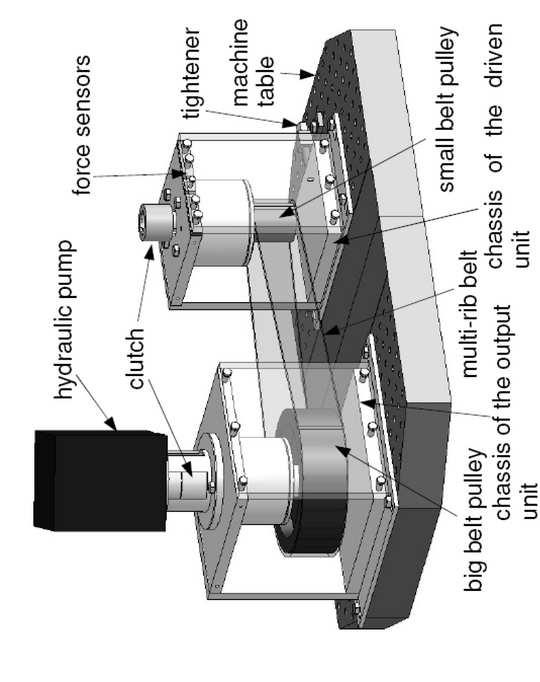
33 Figure06

34 Figure07

35 Figure08
36 Figure09
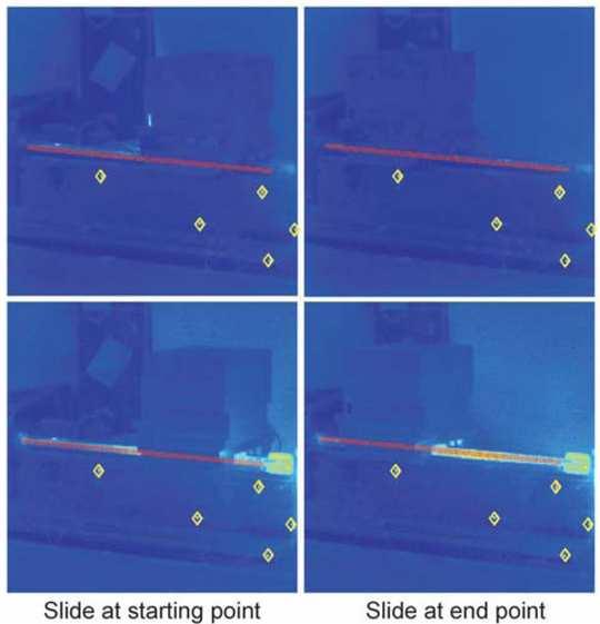
37 Figure10
38 Figure11
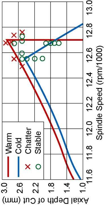
39 Figure12
40 Figure13
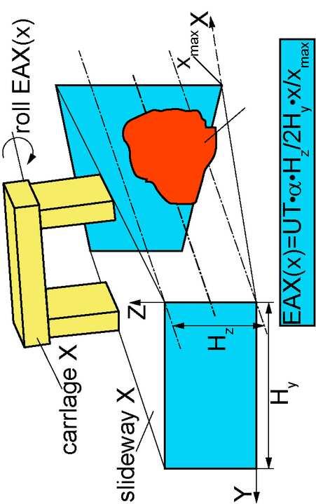
41 Figure14
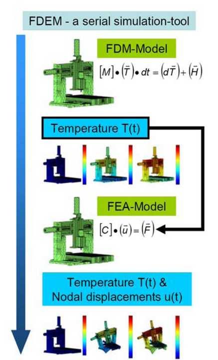
42 Figure15
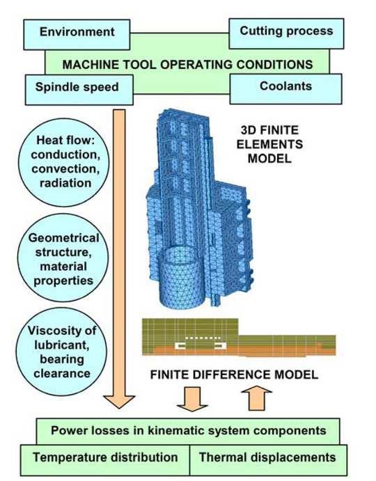
43 Figure16
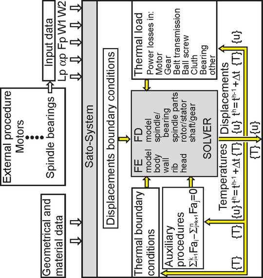
44 Figure17
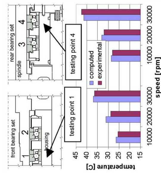
45 Figure18
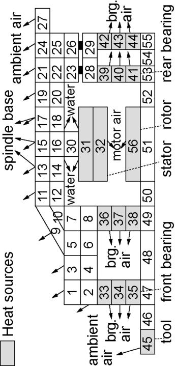
46 Figure19
47 Figure20
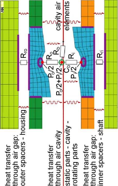
48 Figure21

49 Figure22
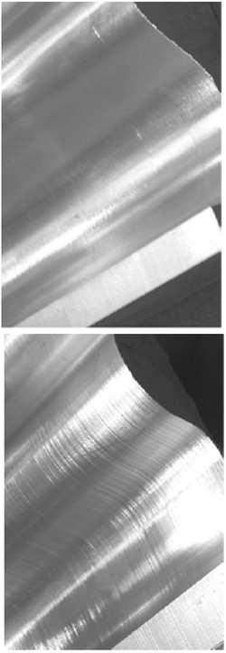
50 Figure23
51 Figure24

52 Figure25
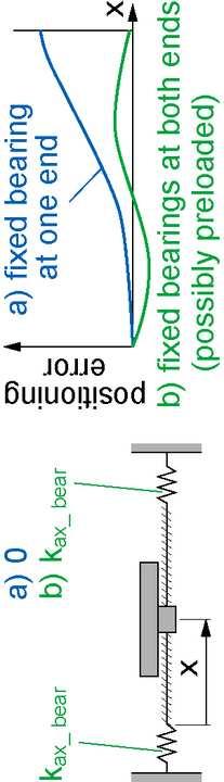
53 Figure26
54 Figure27
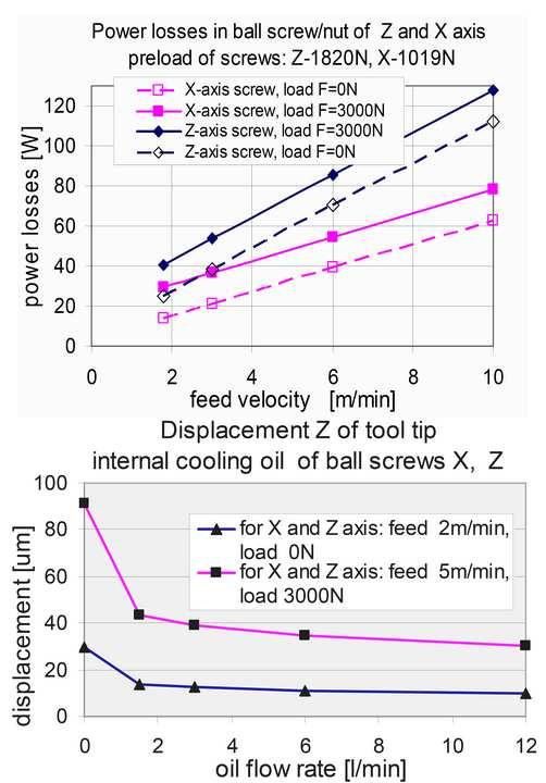
55 Figure28
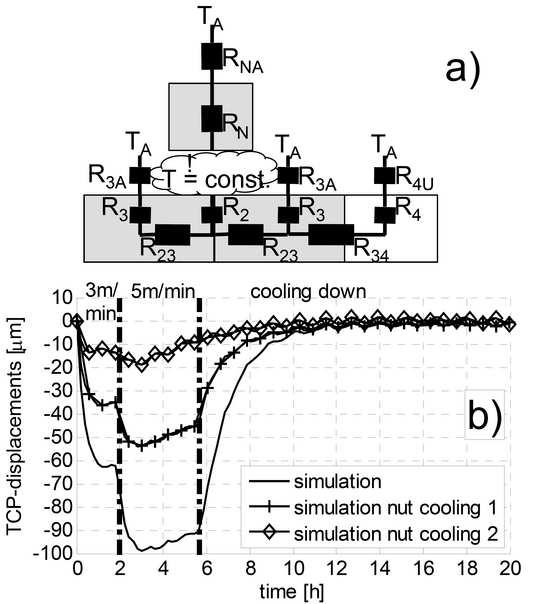
56 Figure29
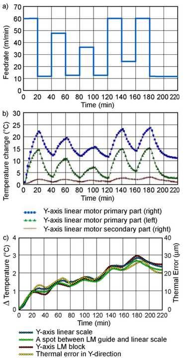
57 Figure30

58 Figure31
59 Figure32
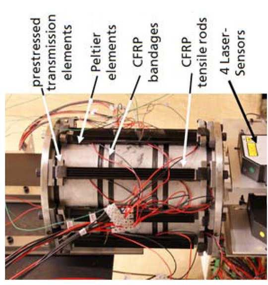
60 Figure33

61 Figure34
62 Figure35
63 Figure36

64 Figure37
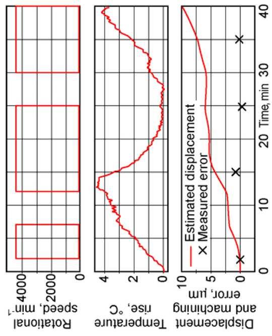
65 Figure38
66 Figure39
67 Figure40
68 Figure41
69 Figure42
70 Figure43
71 Figure44
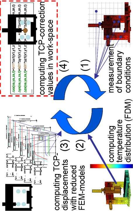
72 Figure45
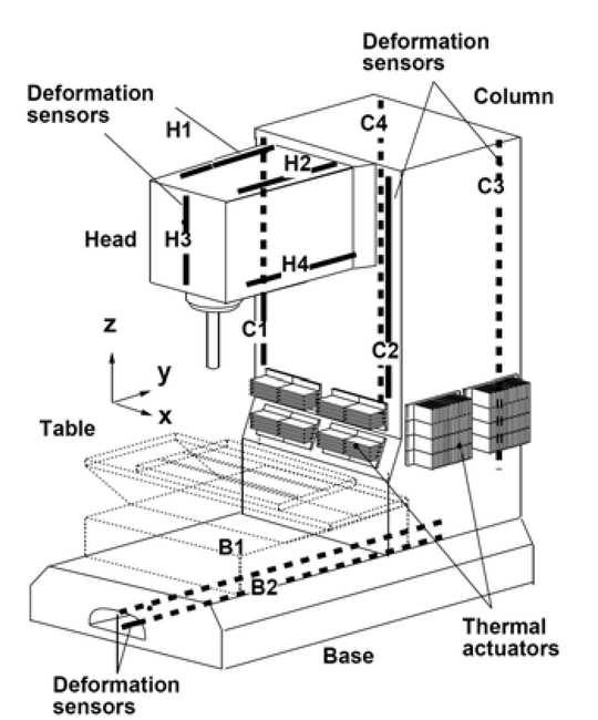
73 Figure46
74 Figure47
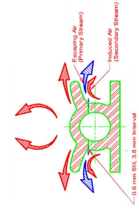
75 Figure48
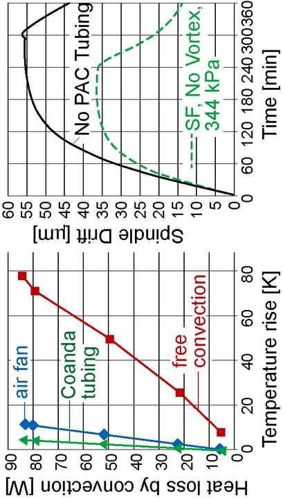
76 Figure49

77 Figure50
78 Figure51
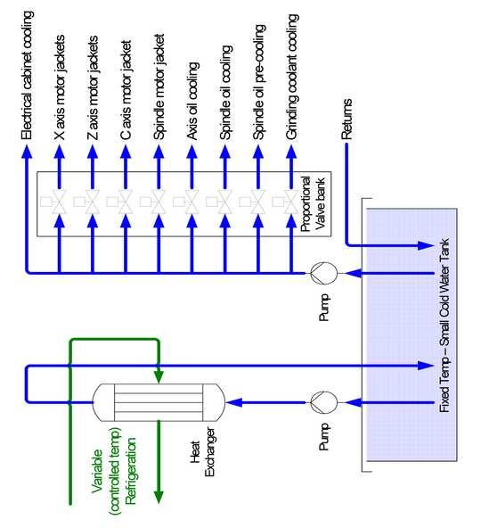
79 Figure52
Research Collection. Thermal issues in 5-axis machine tools. Conference Paper. ETH Library
 Research Collection Conference Paper Thermal issues in 5-axis machine tools Author(s): Wegener, Konrad; Gebhardt, Michael; Mayr, Josef; Knapp, Wolfgang Publication Date: 2014 Permanent Link: https://doi.org/10.3929/ethz-a-010268704
Available online at ScienceDirect. Procedia CIRP 58 (2017 )
") Available online at www.sciencedirect.com ScienceDirect Procedia CIRP 58 (2017 ) 152 157 16 th CIRP Conference on Modelling of Machining Operations Modelling of cutting process impact on machine tool thermal
Available online at www.sciencedirect.com ScienceDirect Procedia CIRP 58 (2017 ) 152 157 16 th CIRP Conference on Modelling of Machining Operations Modelling of cutting process impact on machine tool thermal
KNOWLEDGE BASE AND ASSUMPTIONS FOR HOLISTIC MODELLING AIMED AT REDUCING AXIAL ERRORS OF COMPLEX MACHINE TOOLS 1. INTRODUCTION
 Journal of Machine Engineering, Vol. 13, No. 2, 2013 holistic model, machine tool, power losses, error Jerzy JEDRZEJEWSKI 1 Wojciech KWASNY 1 KNOWLEDGE BASE AND ASSUMPTIONS FOR HOLISTIC MODELLING AIMED
TRACEABILITY STRATEGIES FOR THE CALIBRATION OF GEAR AND SPLINE ARTEFACTS
 TRACEABILITY STRATEGIES FOR THE CALIBRATION OF GEAR AND SPLINE ARTEFACTS W. Beyer and W. Pahl Physikalisch-Technische Bundesanstalt (PTB) 38116 Braunschweig, Germany Abstract: In accordance with ISO 17025,
New concept of a 3D-probing system for micro-components
 Research Collection Journal Article New concept of a 3D-probing system for micro-components Author(s): Liebrich, Thomas; Kanpp, W. Publication Date: 2010 Permanent Link: https://doi.org/10.3929/ethz-a-006071031
A deeper investigation into the thermal drift of a linear axis
 A deeper investigation into the thermal drift of a linear axis O Beltrami STANIMUC Ente Federate UNI via A. Vespucci 7725 Torino, Italia Abstract This presentation shows the results of actual tests performed
TE 75R RESEARCH RUBBER FRICTION TEST MACHINE
 TE 75R RESEARCH RUBBER FRICTION TEST MACHINE Background: The Research Rubber Friction Test Machine offers the ability to investigate fully the frictional behaviour of rubbery materials both in dry and
Traceability of on-machine measurements under a wide range of working conditions
 Traceability of on-machine measurements under a wide range of working conditions Frank Keller, Matthias Franke, Norbert Gerwien, Lisa Groos, Christian Held, Klaus Wendt Traceable in-process dimensional
Static and dynamic testing of machine tools
 Static and dynamic testing of machine tools Thomas Liebrich, Michael Gebhardt, Stefan Thoma, Hop Nguyen, Sascha Weikert, Wolfgang Knapp, Konrad Wegener Institute for Machine Tools and Manufacturing (IWF),
THE NEW 1.1 MN m TORQUE STANDARD MACHINE OF THE PTB BRAUNSCHWEIG/GERMANY
 THE NEW 1.1 MN m TORQUE STANDARD MACHINE OF THE PTB BRAUNSCHWEIG/GERMANY D. Peschel 1, D. Mauersberger 1, D. Schwind 2, U. Kolwinski 2 1 Solid mechanics department, PTB, Germany 2 Gassmann Theiss Messtechnik
Foundations of Ultraprecision Mechanism Design
 Foundations of Ultraprecision Mechanism Design S.T. Smith University of North Carolina at Charlotte, USA and D.G. Chetwynd University of Warwick, UK GORDON AND BREACH SCIENCE PUBLISHERS Switzerland Australia
Position measurement in CNC machines: rotary encoder versus linear transducer, how to cope with the thermal problems
 Position measurement in CNC machines: rotary encoder versus linear transducer, how to cope with the thermal problems A. Frank, F. Ruech Department of Production Engineering, Technical University Graz,
Force/Torque measuring facility for friction coefficient and multicomponent
 DOI 10.516/sensor013/A1. Force/Torque measuring facility for friction coefficient and multicomponent sensors S. Baumgarten 1, D. Röske 1, H. Kahmann 1, D. Mauersberger 1 and R. Kumme 1 1 Physikalisch-Technische
Coordinate Measuring Machines Coordinate INDEX Measuring Machines Coordinate Measuring Machines New Products
 Coordinate Measuring Machines Coordinate Measuring Machines New Products INDEX Coordinate Measuring Machines Crysta-Apex Series L-2, 3 LEGEX Series L-4 Bright-STRATO Series L-5, 6 CP Series L-6 CARBstrato
SAMCEF For ROTORS. Chapter 1 : Physical Aspects of rotor dynamics. This document is the property of SAMTECH S.A. MEF A, Page 1
 SAMCEF For ROTORS Chapter 1 : Physical Aspects of rotor dynamics This document is the property of SAMTECH S.A. MEF 101-01-A, Page 1 Table of Contents rotor dynamics Introduction Rotating parts Gyroscopic
Heat flux and temperature distribution in gear hobbing operations
 Available online at www.sciencedirect.com Procedia CIRP 8 (2013 ) 456 461 14 th CIRP Conference on Modeling of Machining Operations (CIRP CMMO) Heat flux and temperature distribution in gear hobbing operations
Copyright 2017 by Select Calibration Inc. All rights reserved. Temperature Compensation
 Copyright 2017 by Select Calibration Inc. All rights reserved. Temperature Compensation Table of Contents Introduction... 3 Why 20 C... 3 References... 3 Practical CMM Environments...4 CMM Construction
Expedient Modeling of Ball Screw Feed Drives
 S. Frey a A. Dadalau a A. Verl a Expedient Modeling of Ball Screw Feed Drives Stuttgart, February 2011 a Institute for Control Engineering of Machine Tools and Manufacturing Units (ISW), University of
Height Master Page 343. Check Master Page 347. Calibration Tools Page 352
 Calibration Instruments Height Master Page 343 Check Master Page 347 Calibration Tools Page 352 342 Digital Height Master Functions ZERO/ABS DATA/HOLD Auto Power OFF after 20 min. non use Low voltage alarm
Simulation of process of hot pilgrim rolling
 Simulation of process of hot pilgrim rolling YURY B. CHECHULIN, Doctor of Engineering Science, Professor EVGENY U. RASKATOV, Doctor of Engineering Science, Professor YURY A. POPOV, post-graduate student
AF SERIES AWEA MECHANTRONIC CO., LTD. High Performance Vertical Machining Center AGENT ISO 9001 ISO 14001
 AWEA MECHANTRONIC CO., LTD. HEADQUARTERS 629, Suezhetou Section, Kwanpu Rd., Wenshan Li, Hsinpu, Hsinchu, Taiwan TEL : +886-3-88-191 FAX : +886-3-88-19 Website : www.awea.com CENTRAL TAIWAN SCIENCE PARK
CMM Uncertainty Budget
 Table of Contents Purpose...3 Scope...3 Measurement Example...3 Uncertainty Groups...4 Probe Group...5 Calibration Artifact Group...6 Environment Group...7 CMM Group...8 Part Group...10 Conversion of Potential
Dynamic Tests on Ring Shear Apparatus
 , July 1-3, 2015, London, U.K. Dynamic Tests on Ring Shear Apparatus G. Di Massa Member IAENG, S. Pagano, M. Ramondini Abstract Ring shear apparatus are used to determine the ultimate shear strength of
Metrology Prof. Dr Kanakuppi Sadashivappa Bapuji Institute of Engineering and Technology Davangere
 Metrology Prof. Dr Kanakuppi Sadashivappa Bapuji Institute of Engineering and Technology Davangere Lecture 32 Introduction To Comparators, Mechanical Comparators (Refer Slide Time: 00:15) I welcome you
Revision of CMM performance specifications
 Educational Articles: Article nr. 3 Revision of CMM performance specifications Premise The working group (WG) Specifications is one of several working groups of ia.cmm, the International Association of
Assessment of the impact of the articulated probe head angular orientation on the probe head errors distribution
 Assessment of the impact of the articulated probe head angular orientation on the probe head errors distribution Msc. Eng. Piotr Gąska, Msc. Eng. Maciej Gruza, Msc. Eng. Wiktor Harmatys Supervisor: PhD
Measurement method for the proficiency testing program
 APLAC T088 Appendix Measurement method for the proficiency testing program Introductions This measurement method is prepared for use by the APLAC Proficiency Testing Program Photometric measurement of
INVESTIGATION OF BALL SCREWS FOR FEED DRIVE 1. INTRODUCTION
 Journal of Machine Engineering, Vol. 3, No. 4, 203 ball screws, machine tools, rigidity, impact forces Jerzy Z. SOBOLEWSKI INVESTIGATION OF BALL SCEWS FO FEED DIVE The paper presents a method which enables
UNCERTAINTY IN TORQUE CALIBRATION USING VERTICAL TORQUE AXIS ARRANGEMENT AND SYMMETRICAL TWO FORCE MEASUREMENT
 UNCERTAINTY IN TORQUE CALIBRATION USING VERTICAL TORQUE AXIS ARRANGEMENT AND SYMMETRICAL TWO FORCE MEASUREMENT Dieter Kenzler 1, Jörg Oblasser 2, Andreas Subaric-Leitis 2 and Christian Ullner 2 1 ) SCHATZ
Development of Laser Thickness Gauge in Steel Plate Shearing Line
 JFE TECHNICAL REPORT No. 21 (Mar. 2016) Development of Laser Thickness Gauge in Steel Plate Shearing Line TEZUKA Koichi *1 Abstract: JFE Steel has developed a laser thickness gauge for the purpose of guaranteeing
Acknowledgments. Abstract
 Practical application of thermal error correction - 4 case studies J.P. Allen, S.R. Postlethwaite and D.G. Ford The School ofengineering, The University ofhuddersfield, Queensgate, Huddersfield, HD1 SDH,
Emissivity: Understanding the difference between apparent and actual infrared temperatures
 Emissivity: Understanding the difference between apparent and actual infrared temperatures By L. Terry Clausing, P.E. ASNT Certified NDT Level III T/IR, for Fluke Corporation Application Note Taking infrared
Evaluation of active structural vibration control strategies in milling process
 Evaluation of active structural vibration control strategies in milling process Monnin, J. (a); Wegener, K. (a) a) Institute of Machine Tools and Manufacturing, Zurich, Switzerland Keywords: Mechatronics,
Increasing of the Stern Tube Bushes Precision by On-Line Adaptive Control of the Cutting Process
 Increasing of the Stern Tube Bushes Precision by On-Line Adaptive Control of the Cutting Process LUCIAN VASILIU, ALEXANDRU EPUREANU, GABRIEL FRUMUŞANU, VASILE MARINESCU Manufacturing Science and Engineering
Experiment Two (2) Torsional testing of Circular Shafts
 Torsional testing of Circular Shafts") Experiment Two (2) Torsional testing of Circular Shafts Introduction: Torsion occurs when any shaft is subjected to a torque. This is true whether the shaft is rotating (such as drive shafts on engines,
Experiment Two (2) Torsional testing of Circular Shafts Introduction: Torsion occurs when any shaft is subjected to a torque. This is true whether the shaft is rotating (such as drive shafts on engines,
Product description. Compact Modules. Characteristic features. Further highlights
 4 Compact Modules Product description Characteristic features Five fine-tuned sizes based on a compact precision aluminum profile with two integrated pre-tensioned ball rail systems Identical external
BHARATHIDASAN ENGINEERING COLLEGE, NATTRAMPALLI. DEPARTMENT OF MECHANICAL ENGINEERING FAQ
 BHARATHIDASAN ENGINEERING COLLEGE, NATTRAMPALLI. DEPARTMENT OF MECHANICAL ENGINEERING FAQ Year/Sem : III/V Sub.Code/Title: ME6504- METROLOGY & MEASUREMENTS UNIT-I CONCEPT OF MEASUREMENT PART-A 1. Define
Journal of Machine Engineering, 2018, Vol. 18, No. 3, 78 86
 Journal of Machine Engineering, 2018, Vol. 18, No. 3, 78 86 ISSN 1895-7595 (Print) ISSN 2391-8071 (Online) Received: 13 January 2018 / Accepted: 14 August 2018 / Published online: 28 September 2017 accuracy,
Effective Measurement Method of Thermal Deformation of Machine Tools Caused by Linear Axis Motion
 Effective Measurement Method of Thermal Deformation of Machine Tools aused by inear Axis Motion 1. Introduction Shinji Shimizu Noboru Imai Department of Mechanical Engineering Sophia University Tokyo The
Linear guide drives. Synchronous shafts The use of synchronous shafts enables several linear axes to be operated with one drive.
 Linear guide drives Drive concept The linear guides are driven via the hollow shaft in the drive head. The drive head is used to directly install a motor or alternatively (in connection with a center shaft)
Simulation, Prediction and Compensation of Transient Thermal Deformations of a Reciprocating Linear Slide for F8S Motion Error Separation
 Proceedings of the 3 rd International Conference on Mechanical Engineering and Mechatronics Prague, Czech Republic, August 14-1, 2014 Paper No. 139 Simulation, Prediction and Compensation of Transient
L11 Virtual prototyping in machine tool design
 Simulation and Control of Production Plants L11 Virtual prototyping in machine tool design Dipl.-Ing. Dipl.-Wirt. Ing. Benedikt Sitte Steinbachstr. 53 B, Room 408 Tel.: 0241/80-27441 b.sitte@wzl.rwth-aachen.de
THERMAL FIELD ANALYSIS IN DESIGN AND MANUFACTURING OF A PERMANENT MAGNET LINEAR SYNCHRONOUS MOTOR
 THERMAL FIELD ANALYSIS IN DESIGN AND MANUFACTURING OF A PERMANENT MAGNET LINEAR SYNCHRONOUS MOTOR Petar UZUNOV 1 ABSTRACT: The modern Permanent Magnet Linear Synchronous Motors (PMLSM) has a wide range
High Accuracy CMM Measurements at NIST
 High Accuracy CMM Measurements at NIST by John Stoup National Institute of Standards and Technology, USA 2007 CMM Users Meeting - Mexico October 22, 2007 Today s Discussion We will describe the equipment
Open Access Repository eprint
 Open Access Repository eprint Terms and Conditions: Users may access, download, store, search and print a hard copy of the article. Copying must be limited to making a single printed copy or electronic
COMPLETION AND MEASUREMENT UNCERTAINTY BUDGET OF THE MULTI-COMPONENT MEASURING DEVISE FOR FORCE UP TO 1 MN AND TORQUE UP TO 2 KN M
 XXI IMEKO World Congress Measurement in Research and Industry August 30 September 4, 2015, Prague, Czech Republic COMPLETION AND MEASUREMENT UNCERTAINTY BUDGET OF THE MULTI-COMPONENT MEASURING DEVISE FOR
Project PAJ2 Dynamic Performance of Adhesively Bonded Joints. Report No. 3 August Proposed Draft for the Revision of ISO
 NPL Report CMMT(A)81 Project PAJ2 Dynamic Performance of Adhesively Bonded Joints Report No. 3 August 1997 Proposed Draft for the Revision of ISO 11003-2 Adhesives - Determination of Shear Behaviour of
Design and analysis of a piezoelectric film embedded smart cutting tool
 Design and analysis of a piezoelectric film embedded smart cutting tool C Wang*, R Rakowski and K Cheng Advanced Manufacturing and Enterprise Engineering, School of Engineering and Design, Brunel University,
Online Calculation of Guide Rings for Hydraulic Cylinders
 Online Calculation of Guide Rings for Hydraulic Cylinders Fietz Roland Haraldsson Anna 1 Outline 1 2 3 4 5 6 7 Guide Rings General Information / Introduction Guide Rings Synthetic Materials Demarcation
Available online at ScienceDirect. Procedia CIRP 36 (2015 ) CIRP 25th Design Conference Innovative Product Creation
 CIRP 25th Design Conference Innovative Product Creation") Available online at www.sciencedirect.com ScienceDirect Procedia CIRP 36 (2015 ) 111 116 CIRP 25th Design Conference Innovative Product Creation Machine stiffness rating: Characterization and evaluation
Available online at www.sciencedirect.com ScienceDirect Procedia CIRP 36 (2015 ) 111 116 CIRP 25th Design Conference Innovative Product Creation Machine stiffness rating: Characterization and evaluation
PROCESS CONTROL BASIS FOR A COST-EFFECTIVE SELECTIVE SOLDERING PROCESS
 PROCESS CONTROL BASIS FOR A COST-EFFECTIVE SELECTIVE SOLDERING PROCESS Christian Ott Kreuzwertheim, Germany christian.ott@seho.de Heike Schlessmann heike.schlessmann@seho.de Reiner Zoch reiner.zoch@seho.de
Investigation of basic elements loading and tension of heavy hydraulic presses for metallurgical production
 Investigation of basic elements loading and tension of heavy hydraulic presses for metallurgical production Ganush V. I. National metallurgical academe of Ukraine Ostroverhov N. P., Sultan A. V., Dzichkovky
BASIC RESEARCH OF THERMAL TRANSFER SIMULATIONS
 27TH DAAAM INTERNATIONAL SYMPOSIUM ON INTELLIGENT MANUFACTURING AND AUTOMATION DOI:.257/27th.daaam.proceedings.85 BASIC RESEARCH OF THERMAL TRANSFER SIMULATIONS Václav Marek This Publication has to be
The Thermal Challenge
 The Thermal Challenge Benefits of thermal interface materials (TIM) especially dedicated to power electronics The enhancements of semiconductors throughout the last decades targeted the improvement of
A 954 C HD. Technical Description Hydraulic Excavator. Machine for Industrial Applications
 Technical Description Hydraulic Excavator A 95 C HD litronic` Machine for Industrial Applications Operating Weight 165,800 170,0 lb Engine Output 36 hp (0 kw) Technical Data Engine Rating per ISO 99 0
Precision Machine Design 2
 Precision Machine Design 2 Fundamental Principles: 1. Repeatability/Determinism.no workmanship is perfect; the design must make up for its imperfections. H.A. Rowland, 1886 A basic finding from our experience
Mechanics. Centrifugal force Dynamics. What you need: Complete Equipment Set, Manual on CD-ROM included. What you can learn about
 Dynamics Mechanics What you can learn about Centripetal force Rotary motion Angular velocity Apparent force Principle: A body with variable mass moves on a circular path with adjustable radius and variable
Upgrade of 5m-Bench System for Traceable Measurements of Tapes and Rules at SASO-NMCC Dimensional Laboratory
 Upgrade of 5m-Bench System for Traceable Measurements of Tapes and Rules at SASO-NMCC Dimensional Laboratory Bülent ÖZGÜR 1,*, Okhan GANİOĞLU 1, Nasser Al-Qahtani 2, Faisal Al-Qahtani 2 1 TÜBİTAK, National
EUCLID M2 MIRROR MECHANISM
 EUCLID M2 MIRROR MECHANISM Aiala Artiagoitia (1), Carlos Compostizo (1), Laura Rivera (1) (1) SENER, Av. Zugazarte 56, 48930 Las Arenas (Bizkaia) Spain, Email: aiala.artiagoitia@sener.es ABSTRACT Euclid
Lever-type Dial Test Indicators
 Lever-type Dial Test Indicators G-1 Lever-type Dial Test Indicators TESA IP65 Electronic Dial Test Indicators Provides the advantages of a mechanical test indicator with a digital reading. Inductive patented
ADAM PIŁAT Department of Automatics, AGH University of Science and Technology Al. Mickiewicza 30, Cracow, Poland
 Int. J. Appl. Math. Comput. Sci., 2004, Vol. 14, No. 4, 497 501 FEMLAB SOFTWARE APPLIED TO ACTIVE MAGNETIC BEARING ANALYSIS ADAM PIŁAT Department of Automatics, AGH University of Science and Technology
Identification system for short product names. Changes/amendments at a glance. 2 Bosch Rexroth AG OBB omega modules R ( )
") Omega Modules OBB 2 OBB omega modules R9990079 (206-05) Identification system for short product names Short product name Example: O B B - 085 - N N - System = Omega module Guideway = Ball Rail System Drive
Omega Modules OBB 2 OBB omega modules R9990079 (206-05) Identification system for short product names Short product name Example: O B B - 085 - N N - System = Omega module Guideway = Ball Rail System Drive
A STUDY OF THE ACCURACY OF THE MICRO ELECTRICAL DISCHARGE MACHINING DRILLING PROCESS
 A STUDY OF TE ACCURACY OF TE MICRO ELECTRICAL DISCARGE MACINING DRILLING PROCESS D.T. Pham, S.S. Dimov, S. Bigot, A. Ivanov, and K. Popov Manufacturing Engineering Centre, School of Engineering, Cardiff
Strain Measurement Techniques for Composite Coupon Testing
 Strain Measurement Techniques for Composite Coupon Testing Introduction Characterization of the properties of anisotropic and inhomogeneous composite materials for use in demanding structural applications
EFFECT OF HYDRODYNAMIC THRUST BEARINGS ON ROTORDYNAMICS
 The 12th International Symposium on Transport Phenomena and Dynamics of Rotating Machinery Honolulu, Hawaii, February 17-22, 2008 ISROMAC12-2008-20076 EFFECT OF HYDRODYNAMIC THRUST BEARINGS ON ROTORDYNAMICS
3D Simulation of the Plunger Cooling during the Hollow Glass Forming Process Model, Validation and Results
 Thomas Bewer, Cham, CH 3D Simulation of the Plunger Cooling during the Hollow Glass Forming Process Model, Validation and Results A steady state model to describe the flow and temperature distribution
Introduction To Metrology
 Introduction To Metrology Meaning of Metrology Metrology is the science of measurement. Metrology may be divided depending upon the quantity to be measured like metrology of length, metrology of time.
Mitigation of Diesel Generator Vibrations in Nuclear Applications Antti Kangasperko. FSD3020xxx-x_01-00
 Mitigation of Diesel Generator Vibrations in Nuclear Applications Antti Kangasperko FSD3020xxx-x_01-00 1 Content Introduction Vibration problems in EDGs Sources of excitation 2 Introduction Goal of this
EXPERIMENTAL RESEARCH REGARDING TRANSIENT REGIME OF KINEMATIC CHAINS INCLUDING PLANETARY TRANSMISSIONS USED IN INDUSTRIAL ROBOTS
 International Journal of Modern Manufacturing Technologies ISSN 2067 3604, Vol. VIII, No. 1 / 2016 EXPERIMENTAL RESEARCH REGARDING TRANSIENT REGIME OF KINEMATIC CHAINS INCLUDING PLANETARY TRANSMISSIONS
Modelling of a dynamic torque calibration device and determination of model parameters
 ACTA IMEKO June 2014, Volume 3, Number 2, 14 18 www.imeko.org Modelling of a dynamic torque calibration device and determination of model parameters Leonard Klaus, Thomas Bruns, Michael Kobusch Physikalisch-Technische
ISO/TR TECHNICAL REPORT. Gears Thermal capacity Part 1: Rating gear drives with thermal equilibrium at 95 C sump temperature
 TECHNICAL REPORT ISO/TR 14179-1 First edition 2001-07-15 Gears Thermal capacity Part 1: Rating gear drives with thermal equilibrium at 95 C sump temperature Engrenages Capacité thermique Partie 1: Capacité
Dynamic stiffness compensation with active aerostatic thrust bearings
 Dynamic stiffness compensation with active aerostatic thrust bearings G. Aguirre, F. Al-Bender, H. Van Brussel K.U.Leuven, Department of Mechanical Engineering, Celestijnenlaan 300 B, B-3001, Heverlee,
ISO INTERNATIONAL STANDARD. Rolling bearings Thermal speed rating Calculation and coefficients
 INTERNATIONAL STANDARD ISO 1512 First edition 200-12-01 Rolling bearings Thermal speed rating Calculation and coefficients Roulements Vitesse de référence thermique Calculs et facteurs de correction Reference
Heat Transfer Analysis of Machine Tool Main Spindle
 Technical Paper Heat Transfer Analysis of Machine Tool Main Spindle oshimitsu HIRASAWA Yukimitsu YAMAMOTO CAE analysis is very useful for shortening development time and reducing the need for development
Controlling Thermal Expansion
 Controlling Thermal Expansion Strategies for Maximizing the Repeatability of your Linear Stage By David Goosen, Mechanical Engineering Team INTRODUCTION Most of us are aware that all common engineering
Lever-type Dial Test Indicators
 Lever-type Dial Test Indicators www.tesatechnology.com G-1 Lever-type Dial Test Indicators TESA IP65 Electronic Dial Test Indicators Provides the advantages of a mechanical test indicator with a digital
Coupling System for Ultra Precision Machining
 Journal of Mechanics Engineering and Automation 6 (2016) 301-306 doi: 10.17265/2159-5275/2016.06.006 D DAVID PUBLISHING Eike Foremny, Christian Schenck and Bernd Kuhfuss Bremen Institute for Mechanical
EUROMASTER HYDRAULIC PRESSBRAKES
 EUROMASTER HYDRAULIC PRESSBRAKES EUROMASTER HYDRAULIC PRESSBRAKES 02_ EUROMASTER Euromaster 50250 The Euromaster has been developed as a modern pressbrake with electronic levelling and depth control Synchro
Parametric Study of Shaft Subjected To Pure Bending
 Page167 Parametric Study of Shaft Subjected To Pure Bending Amar Kumar Patel*, Akash Kumar Patel**, Prajnasu Biswal***, & Satya Narayan Tripathy**** *Mechanical Department, Gandhi Institute of Engineering
Thermal Analysis. inspiration
 white paper Thermal Analysis inspiration summary In this white paper we define and then outline the concept of thermal analysis as it relates to product design. We discuss the principles of conduction,
Study on Tire-attached Energy Harvester for Lowspeed Actual Vehicle Driving
 Journal of Physics: Conference Series PAPER OPEN ACCESS Study on Tire-attached Energy Harvester for Lowspeed Actual Vehicle Driving To cite this article: Y Zhang et al 15 J. Phys.: Conf. Ser. 66 116 Recent
Control Engineering BDA30703
 Control Engineering BDA30703 Lecture 4: Transducers Prepared by: Ramhuzaini bin Abd. Rahman Expected Outcomes At the end of this lecture, students should be able to; 1) Explain a basic measurement system.
NATIONAL CERTIFICATE (VOCATIONAL) APPLIED ENGINEERING TECHNOLOGY NQF LEVEL 4 NOVEMBER 2009
 APPLIED ENGINEERING TECHNOLOGY NQF LEVEL 4 NOVEMBER 2009") NATIONAL CERTIFICATE (VOCATIONAL) APPLIED ENGINEERING TECHNOLOGY NQF LEVEL 4 NOVEMBER 2009 (6021024) 30 October (Y-Paper) 13:00 16:00 A non-programmable scientific calculator may be used. This question
NATIONAL CERTIFICATE (VOCATIONAL) APPLIED ENGINEERING TECHNOLOGY NQF LEVEL 4 NOVEMBER 2009 (6021024) 30 October (Y-Paper) 13:00 16:00 A non-programmable scientific calculator may be used. This question
Newton s 2nd Law with demonstration track and Cobra4
 Newton s 2nd Law with demonstration track TEP Related topics Velocity, acceleration, force, acceleration of gravity. Principle The distance-time law, the velocity-time law, and the relationship between
Performance Enhancement of Grinding Processes Mutual Interaction between the Material Removal Process and the Machine Tool
 CONTRIBUTION Performance Enhancement of Grinding Processes Mutual Interaction between the Material Removal Process and the Machine Tool Professor Ichiro INASAKI Institute of Science and Technology Research
Selection Calculations For Linear & Rotary Actuators
 H-8 For Electric Linear Slides and Electric Cylinders First determine your series, then select your product. Select the actuator that you will use based on the following flow charts: Selection Procedure
CRYSTA-APEX C. The modular system for 3D CNC coordinate measurement in the production environment. Quick, versatile and high performing.
 Coordinate Measuring Machines CRYSTA-APEX C The modular system for 3D CNC coordinate measurement in the production environment. Quick, versatile and high performing. Future-proofed high performance. CRYSTA-APEX
CHAPTER 6 FRICTION AND WEAR ANALYSIS FOR BUSHING
 CHAPTER 6 FRICTION AND WEAR ANALYSIS FOR BUSHING 6.1 TEST RIG SETUP FOR THE FRICTION AND WEAR ANALYSIS Knowing the frictional coefficient is important for the determination of wear loss and power loss
DISCONTINUED PRECISION MEASURING FOWLER CALIPERS 1 - VERNIER CALIPERS 4 - ELECTRONIC CALIPERS
 FOWLER CALIPERS 1 - VERNIER CALIPERS 4 - ELECTRONIC CALIPERS 52-058-016 Fine quality vernier calipers are constructed of stainless steel. 52-057-004 offers 3-way measurement to accuracy. 52-058-XXX series
Development of the Screw-driven Motors by Stacked Piezoelectric Actuators
 Proceedings of the 4th IIAE International Conference on Industrial Application Engineering 2016 Development of the Screw-driven Motors by Stacked Piezoelectric Actuators Shine-Tzong Ho a,*, Hao-Wei Chen
Clausing Industrial, Inc. Variable Speed 20" Single and Multi-spindle, Belt Drive Industrial Drill Presses
 www.clausing-industrial.com Variable Speed 20" Single and Multi-spindle, Belt Drive Industrial Drill Presses Clausing Industrial, Inc. Two Speed Variable Speeds 150-2000rpm Variable Speeds 200-1300rpm
Special edition paper
 Development of New Aseismatic Structure Using Escalators Kazunori Sasaki* Atsushi Hayashi* Hajime Yoshida** Toru Masuda* Aseismatic reinforcement work is often carried out in parallel with improvement
Standard Test Methods for Glass-Bonded Mica Used as Electrical Insulation 1
 Designation: D 1039 94 (Reapproved 1999) e1 An American National Standard Standard Test Methods for Glass-Bonded Mica Used as Electrical Insulation 1 This standard is issued under the fixed designation
Thermal error compensation for a high precision lathe
 IWMF214, 9 th INTERNATIONAL WORKSHOP ON MICROFACTORIES OCTOBER 5-8, 214, HONOLULU, U.S.A. / 1 Thermal error compensation for a high precision lathe Byung-Sub Kim # and Jong-Kweon Park Department of Ultra
ABB temperature measurement Radiation thermometry. Measurement made easy. Process temperature measurement practice--non-contacting
 Whitepaper_ WP_T_Non-Contacting_Temperature_Measurement ABB temperature measurement Radiation thermometry Measurement made easy Process temperature measurement practice--non-contacting By Gary Freeman,
Efficient runner safety assessment during early design phase and root cause analysis
 IOP Conference Series: Earth and Environmental Science Efficient runner safety assessment during early design phase and root cause analysis To cite this article: Q W Liang et al 2012 IOP Conf. Ser.: Earth
VIBRATION RESPONSE OF AN ELECTRIC GENERATOR
 Research Report BVAL35-001083 Customer: TEKES/SMART VIBRATION RESPONSE OF AN ELECTRIC GENERATOR Paul Klinge, Antti Hynninen Espoo, Finland 27 December, 2001 1 (12) Title A B Work report Public research
Key words: Polymeric Composite Bearing, Clearance, FEM
 A study on the effect of the clearance on the contact stresses and kinematics of polymeric composite journal bearings under reciprocating sliding conditions Abstract The effect of the clearance on the
Sensorless compensation system for thermal deformations of ball screws in machine tools drives
 Sensorless compensation system for thermal deformations of ball screws in machine tools drives Michał Kowal Poznan University of Technology, Piotrowo 3 Street, 60-965 Poznan, Poland e-mail address: michal.kowal@put.poznan.pl
Rotary modules.
 Rotary modules www.comoso.com www.comoso.com Rotary modules ROTARY MODULES Series Size Page Rotary modules RM swivel unit 156 RM 08 160 RM 10 162 RM 12 164 RM 15 168 RM 21 172 RM rotor 176 RM 50 180 RM