Simulation of a non-equilibrium helium plasma bullet emerging into oxygen at high pressure ( Torr) and interacting with a substrate
|
|
|
- Alisha Briggs
- 5 years ago
- Views:
Transcription
1 Simulation of a non-equilibrium helium plasma bullet emerging into oxygen at high pressure ( Torr) and interacting with a substrate Wen Yan 1,2 and Demetre J. Economou 2,* 1 School of Physics and Materials Engineering Dalian Nationalities University Dalian , People's Republic of China 2 Plasma Processing Laboratory Department of Chemical and Biomolecular Engineering University of Houston Houston, TX USA MS # JR R Revised September 2, economou@uh.edu 1
2 Abstract A two-dimensional computational study of a plasma bullet emanating from a helium gas jet in oxygen ambient at high pressure ( Torr) was performed, with emphasis on the bullet interaction with a substrate. Power was applied in the form of a trapezoidal +5 kv pulse lasting 150 ns. A neutral gas transport model was employed to predict the concentration distributions of helium and oxygen in the system. These were then used in a plasma dynamics model to investigate the characteristics of the plasma bullet during its propagation and interaction with a substrate. Upon ignition, the discharge first propagated as a surface wave along the inner wall of the containing tube, and then exited the tube with a well-defined ionization front (streamer or plasma bullet). The plasma bullet evolved from a hollow (donut-shaped) feature to one where the maximum of ionization was on axis. The bullet propagated in the gap between the tube exit and the substrate with an average speed of ~ m/s. Upon encountering a metal substrate, the bullet formed a conductive channel to the substrate. Upon encountering a dielectric substrate, the bullet turned into an ionization wave propagating radially along the substrate surface. For a conductive substrate, the radial species fluxes to the surface peaked on the symmetry axis. For a dielectric substrate, a ring-shaped flux distribution was observed. The footprint of plasma-surface interaction increased by decreasing the gap between tube exit and substrate, or decreasing the relative permittivity of an insulating substrate, or decreasing pressure. As the system pressure was lowered from 760 to 250 Torr, the discharge was initiated earlier, and the plasma bullet propagation speed increased. A reverse electric field developed during the late stages of the ramp-down of the pulse, which accelerated electrons forming a brief backward discharge. 2
3 1. INTRODUCTION Non-thermal (cold) high pressure (notably 1 atm) plasmas are investigated intensely because of current and future applications ranging from surface modification and materials processing to plasma medicine 1 6. Various types of non-thermal plasma sources have been developed and studied 7,8. In particular, cold atmospheric pressure plasma jets (APPJ) have attracted considerable attention, compared to other plasmas in confined geometries, primarily due to their ability of delivering various active species to relatively remote locations for localized treatment. Understanding the physical and chemical processes taking place in the plasma jet is critically important. To this end, numerous experimental and simulation studies have contributed to a better understanding of these systems. For example, it was demonstrated that the plasma jet is typically composed of streamers or plasma bullets propagating at supersonic speeds ( m/s) 9,10. Images revealed that the bullet is in fact hollow, having a donut-shaped structure 11,12. Plasma diagnostics showed that the streamer dynamics depends on electron temperature 13. Using two-photon laser-induced fluorescence spectroscopy, the O number density in a plasma jet emerging in 1 atm air ambient was found to reach cm Experimental measurements have been complemented by modeling and simulation. Several research groups have developed two-dimensional (2-D) axisymmetric models to explain the experimental observations. Using the local field approximation, Naidis 15,16 successfully simulated the donut-shaped plasma bullet and showed that the formation of such structure is due to radial non-uniformity of the electron impact ionization rate of the gas 3
4 species. The computational studies by Breden et al. 17,18 and Norberg et al. 19, provided valuable insights into the dynamics of plasma bullet propagation and its interaction with surfaces. Plasma jets can be generated in different gases using different means of electrical excitation. A typical plasma jet consists of a dielectric tube through which a jet of noble gas exhausts into an ambient gas. High voltage nanosecond pulse waveforms are applied to a ring electrode wrapped around the tube to form a plasma jet 10. The gas is near room temperature, making these devices ideal for the treatment of thermosensitive materials (e.g., human skin). Previous experimental studies by Xian et al 20 and Schmidt-Bleker et al 21 investigated He plasma jets and the resulting bullets propagating in oxygen ambient. Xian et al. 20 observed that the plasma jet became shorter and thinner by increasing the mole fraction of O 2 in the ambient gas. Winter et al. 22 found a drastic decrease in the measured metastable He density by decreasing the mole fraction of oxygen in the ambient gas. Several simulations were performed to investigate the generation mechanism of reactive oxygen species in discharges fed by He/O 2 mixtures. Schmidt-Bleker et al. 21 investigated, by a combination of simulation and experiment, the influence of electronegativity of the ambient gas on the propagation of the plasma bullet. Despite the plethora of investigations, however, several aspects of the effect of substrate conductivity and system pressure on the plasma jet and its interaction with surfaces have not been elucidated. In this work, a two dimensional axisymmetric fluid model was developed to investigate the discharge dynamics of a helium high pressure plasma jet emerging in oxygen ambient. Physical processes including discharge ignition and propagation inside the tube, plasma bullet 4
5 propagation in the open gap, and its interaction with a substrate were studied. Particular emphasis was placed on the effect of the conductivity of the substrate surface (conductor vs. insulator) and system pressure ( Torr). 2. MODEL DEVELOPMENT The plasma jet configuration studied in this work is shown in Fig. 1. The overall problem was divided into two parts: a neutral gas flow model and a plasma dynamics model. Fig. 1(a) shows the simulation domain; only the right half of the axisymmetric (r, z) system is shown. The larger domain (ADEG) was used for the neutral gas model, while the smaller domain (ACFG) was used for the plasma dynamics model. A detail of the plasma region is shown in Fig. 1(b). Helium gas flowed through a dielectric tube (relative permittivity of 4) with 2 mm ID (inner diameter). A high voltage (HV) ring electrode (1.5 mm long with 4 mm ID and 4.4 mm OD (outer diameter)) was embedded in the dielectric wall, similar to the works by Raja et al 17,18 and Lu et al 26. The distance between the downstream edge of the HV electrode and the tube exit was 3.5 mm. A trapezoidal voltage pulse with amplitude of +5 kv was applied to the ring electrode, see Fig. 1(c). The rise and fall time of the voltage was 10 ns each. Thus, the voltage on the electrode was steady at 5 kv for 130 ns. Following the common practice 15,18,19 only a single pulse was simulated. This implies that the pulse OFF time interval is long enough (~ gas residence time) for the system volume to be replenished with fresh gas, before the next voltage pulse is applied. The substrate was placed 5 mm away from the tube exit perpendicular to the jet axis. Both conductive and insulating substrates were examined. In the 5
 O 2 1.5mm +HV tube 2 mm 4 mm (b) (c) Figure 1.")
6 case of insulator (relative permittivity either 5 or 15), the thickness of the dielectric layer facing the plasma was 0.5 mm. This layer was on top of a grounded metal wall. Substrate G F E I H 5 mm He 5 mm z +HV A B r C D (a) O 2 1.5mm +HV tube 2 mm 4 mm (b) (c) Figure 1. Plasma jet configuration studied: (a) Computational domain; due to axisymmetric (r, z) nature of the problem, only half of the domain is shown. The axis of symmetry is AG. Helium is fed through boundary AB (1 mm radius), while O 2 enters through annular boundary CD. (b) Detail of the plasma region, not showing the region of injection of the ambient oxygen gas. (c) Applied voltage. 2.1 Neutral gas flow model The helium working gas flowed through the dielectric tube and emerged into an oxygen ambient. The average gas flow velocity in the tube was 5 m/s (at 760 Torr), corresponding to a Reynolds number of 86, implying laminar flow. The neutral gas flow model consisted of the total mass continuity equation (Eq. 1), the momentum conservation (Navier-Stokes) equations (Eq. 2), and the species mass balance equation (Eq. 3): 0 (1) (2) 0 (3) 6
7 Here is the mass-average velocity of the mixture, is the mixture density (helium = kg m -3, oxygen = kg m -3 at 760 Torr), is viscosity (helium = Pa s and oxygen = Pa s), and is the body force. and are mass fraction and diffusion flux of species, respectively. For laminar flow,, where is the (molecular) diffusion coefficient (helium in oxygen = m s at 760 Torr 26 ). The effect of the plasma on the neutral gas flow was not considered in this work. An indication of the weak interaction between neutral gas flow and plasma under the present conditions is the fact that the temperature of the fluid in the jet hardly increases above ambient 18,27,28. The boundary conditions are summarized in Table 1, with the corresponding boundaries shown in Fig. 1(a). The velocity of the entrained oxygen ambient gas was set at 0.3 m/s (at 760 Torr) on face CD in Fig. 1(a) 29. The governing equations (1)-(3) were solved using a steady-state solver in COMSOL 30. Table 1. Boundary conditions for the neutral gas model. Boundaries AB, CD, etc. are shown in Fig. 1(a). and are the velocity components in the axial and radial direction, respectively. n is the unit normal vector pointing towards the boundary. Values of are at 760 Torr, and scale inversely proportionally to pressure. AB CD DE EG BIHC 5 m/s 0.3 m/s =0a a Corresponds to zero stress. 0 r 0 r z 0 0 z 0 0 7
8 2.2 Plasma dynamics model Plasma dynamics was governed by a fluid model, which is based on the continuity Eq. (4), with the drift-diffusion approximation Eq. (5), the electron energy conservation Eq. (6) and Poisson s Eq. (7) 31,32 : (4) (5) Γ, 3 (6) Φ (7) where subscripts and indicate the th species and electrons, respectively. is the species density, is the flux (in the drift-diffusion approximation), is the rate of production or consumption of species i in reaction j, is the charge of species i; and are mobility and diffusion coefficient, respectively. is the sign function (positive or negative), is the electric field, Φ is the electric potential. is the electron energy density, is the electron equivalent temperature. and are the energy loss during inelastic collisions and the corresponding reaction rate, respectively.,, and are the electron mass, gas species mass, electron-neutral momentum transfer collision frequency, and gas temperature, respectively. The right-hand side of the electron energy Eq. (6) consists of three source terms in the order shown: Joule heating, inelastic and elastic collisional energy exchange, respectively. Moreover, in Eq. (7), is the relative permittivity of the dielectric and 0 is the vacuum permittivity. Table 2 summarizes the boundary conditions of the plasma dynamics model. The boundary conditions for the particle flux and the electron energy density on solid walls were: 8
9 (8) (9) (10) 2 (11) where m is the wall reaction probability of neutral species m. Table 2. Boundary conditions of the plasma dynamics model. Boundaries AB, CD, etc. are shown in Fig. 1(a). Ring is the high voltage electrode. a is the applied voltage. AG AB BC CH HF GF BIH Ring Φ r 0 r 0 r 0 r 0 Φ r 0 z z z z Φ z 0 r 0 Eq.(8) Eq.(8) - r 0 Eq.(9) Eq.(9) - r 0 Eq.(10) Eq.(10) - r 0 Eq.(11) Eq.(11) - Φ z Eq.(13) a where subscripts,, and indicate electrons, ions, metastables and electron energy, respectively. is the unit normal vector pointing towards the surface and i = 0.01 is the secondary electron emission coefficient by ion impact. T i and T g are the ion and background gas temperature, respectively, taken as T i = T g = 300 K; k b is the Boltzmann constant, and and are switching functions depending on the dot product of and : , (12) 9
10 The potential at the surface of a dielectric was calculated according to Gauss s law, (13) where and are the electric displacement vectors, is the net charge density accumulated on the dielectric surface, and and are the normal components of the electron current density and total ion current density on the surface, respectively. In the case of conductive substrate the potential of the substrate was set to ground (i.e., zero). A simplified chemistry mechanism 15,33 was used in this investigation which involved reactions in the gas phase as well as recombination and quenching reactions on solid surfaces. The species considered in the model were He, metastable He * = He(2 3 S 1 ), excimer He 2 * = He 2 ( 3 u ), He +, He 2 +, O 2, O, O 2 -, O 2 +, and electrons. The gas phase reaction mechanism is shown in Table 3. For reactions involving electron collision with heavy species, the reaction rate coefficients were obtained using BOLSIG+, a Boltzmann equation solver 34. The electron transport coefficients were also calculated using BOLSIG+. The cross sections used in the calculation were obtained from [35]. The transport coefficients for ions and metastables were obtained from [25,36]. Photo-ionization was not considered in the model; following published works 15,16, a background pre-ionization was assumed, instead. According to Breden et al. 17, photoionization can affect the streamer (plasma bullet) propagation speed but it is not needed to sustain the steamer. The wall destruction probability of He *, He 2 *, He +, He 2 +, O 2 -, and O 2 + was set equal to unity, whereas the wall recombination probability of O-atoms was The system of Eqs. (4)-(7), (13) was solved by a time-dependent solver in COMSOL 30. Triangular finite elements were used with a finer grid in the region r < 1 mm and close to the substrate surface. The minimum mesh size was 0.01 mm. Nearly 12,000 10
11 elements were employed and the total number of degrees of freedom was ~ 1,000,000. Reducing the grid size to half of that of the base case, yielded profiles essentially identical to the base case, implying grid convergence. A question can arise concerning the effect of rotational and vibrational states of molecular oxygen on the system behavior. A test simulation including several vibrational excitation channels of oxygen showed no significant effect of these processes on the plasma bullet dynamics. This may be due to the high electron temperatures in the system (see below) that favor high activation energy processes. Indeed, plasma bullet propagation is governed by electron-impact ionization of helium neutral and oxygen molecules 17. The neutral gas flow model and the plasma dynamics model were solved sequentially. This time splitting approach is valid because of the disparate time scales of the neutral gas flow and the plasma flow. In addition, the coupling between the neutral gas flow model and the plasma dynamics model is rather weak 18,27,28. First, the neutral gas flow model was solved to obtain the steady-state fluid velocity and concentration (He and O 2 ) profiles. These were in turn used as input to the plasma dynamics model to obtain the time-dependent charged and minority neutral species concentrations as well as the electric field profiles. This simulation method is similar to that reported by Naidis 15,16 and Breden and Raja
12 Table 3. Reactions included in the model. Helium-Oxygen chemistry (units are molecules-meter-electron volt) Index Reaction A B C Threshold energy(ev) Ref (R1) He+e e+he * BOLSIG (R2) He+e 2e+He + BOLSIG ,35 (R3) e+he * 2e+He (R4) 2He * e+he+he (R5) e+he * e+he (R6) e+he * + 2 2e+He (R7) e+he + 2 He * +He (R8) He * +2He He * 2 +He (R9) He + +2He He + 2 +He (R10) e+he + He * (R11) 2e+He + e+he * (R12) - e+2o 2 O 2 +O ,35 (R13) e+o 2 e+o 2 (v3) BOLSIG (R14) e+o 2 e+o 2 (v4) BOLSIG ,35 (R15) e+o 2 e+o 2 (a1) BOLSIG ,35 (R16) e+o 2 e+o 2 (b1) BOLSIG ,35 (R17) e+o 2 e+o 2 (exc) BOLSIG ,35 (R18) e+o 2 e+o+o BOLSIG ,35 (R19) e+o 2 e+o+o(1d) BOLSIG ,35 (R20) + e+o 2 2e+O 2 BOLSIG ,35 (R21) O - 2 +O + 2 +M 2O 2 +M Notes: Reaction rate coefficients were described by an Arrhenius form A /. For electron impact reactions, T is the electron temperature in ev, and for reaction between heavy species, T is the gas temperature also in ev. Species M in reaction (R21) represents a third-body. 34,35 3. RESULTS AND DISCUSSION The base case parameter values used in the simulation were as follows: geometry as shown in Figure 1, pressure 760 Torr, gas temperature 300 K, applied voltage +5 kv for 150 ns (including 10 ns rise time and 10 ns fall time), 5 mm gap between the tube exit and the substrate, and conductive (metal) substrate. The effect of a 3 mm gap, a 0.5 mm-thick insulating substrate having relative permittivity of 5 or 15, as well as the effect of system 12
13 pressure ( Torr) was investigated. Table 4. Base case parameter values and range studied. Parameter Base case value Range investigated Pressure 760 Torr 250, 500, 760 Torr Applied voltage and duration Gap between tube exit and substrate 5 kv, 150 ns 5 mm 3, 5 mm Substrate Conductor Insulator Relative permittivity of insulating substrate 5 5, Steady state properties of the neutral gas Figure 2 shows the helium mole fraction distribution for the base case as well as for a 3 mm gap. The helium mole fraction is essentially unity inside the tube. Back diffusion of oxygen into the tube is negligible since the corresponding Peclet number is Pe= u L/D~ 350 >>1 where u is the average helium flow velocity in the tube, L is the tube length and D is the diffusion coefficient of oxygen in helium. As the flow exits the tube, the helium mole fraction decreases in both the z- and r-direction, due to mixing (by convective diffusion) of the ambient oxygen with the helium gas. When the gas reaches the substrate, it flows radially outwards (stagnation point flow), which is similar to previous simulation results 18. As expected, in the 5 mm gap case, the pure helium core near the substrate location has smaller diameter, since oxygen mixing occurs for longer time, compared to the 3 mm gap. The mole fraction distribution of He in the He/O 2 mixture is critical for confining and guiding the 13
 because the ionization rate coefficient vs.")
14 plasma bullet. In fact, the radial extent of the bullet is confined to the region where the He mole fraction is above ~ The plasma cannot be sustained beyond a certain concentration of oxygen (a certain radial position) because the ionization rate coefficient vs. E/N (electric field to neutral gas density ratio) decreases sharply as the oxygen mole fraction in the He-O 2 mixture increases 15. The diameter of the He core of the jet shrinks as a function of distance from the tube exit, then expands upon striking the substrate (see below). The constriction of the diameter of the He core of the jet is not as pronounced in the 3 mm compared to the 5 mm gap. Figure 2. Helium mole fraction profiles for (a) 5 mm gap between the tube exit and the substrate, and (b) 3 mm gap. Other parameters at their base case values. 3.2 Conductive substrate Although it appears continuous to the naked eye, the discharge is actually composed of fast ionization waves (streamers, also called plasma bullets) traveling at supersonic speeds in the dielectric tube and in the gap between the tube exit and the substrate 7. The spatio-temporal distribution of the ionization rate is shown in Fig. 3 for conductive (a), and 14

15 insulating (b), substrates. Over a period of the applied voltage pulse, the discharge starts as a surface ionization wave adjacent to the containing tube wall. A plasma bullet then forms that is launched in the gap at t ~22 ns, and propagates towards the substrate. The bullet starts as a donut-shaped structure (ionization peaks off axis), but the hole fills in as the bullet travels further downstream, resulting in peak ionization on axis. The average propagation speed of the plasma bullet in the gap is ~ m/s, in the range of values reported by other investigators [7 and references therein]. Upon striking a metal (conductive) substrate (Fig. 3a) at t ~45 ns, the plasma bullet forms a conductive channel to the substrate. Eventually ionization is suppressed when the He mole fraction drops below ~0.99. Figure 3. Spatiotemporal evolution of the total ionization rate (including reactions (R2), (R3), (R4), (R6) and (R20), see Table 3) for conductive (a), and insulating (b), substrates. The plasma bullet is shown at different times during a voltage pulse. Rectangular insets show expanded scale of the plasma bullet at 45 and 60 ns for the conductive substrate and 90 and 140 ns, for the insulating substrate. For t = 90 and 140 ns, the ionization rate is multiplied by 10 for better visualization. Previous computational studies (Naidis et al 21, Breden et al 38, Boeuf et al 39, and Lu et al 26 ) have provided insights into the structure of the plasma bullet emerging in air ambient. 15
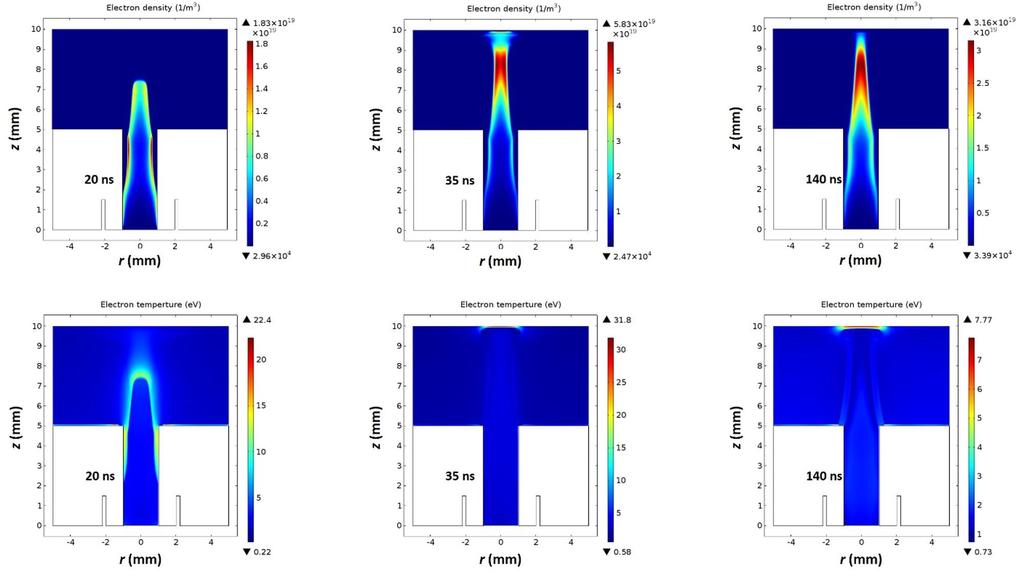
16 The main difference in the structure of the plasma bullet between previous studies and our work is that the radial extend and spatial evolution of the ionization profile of our plasma bullet follows the evolution of the helium core of Fig. 2, i.e., the bullet constricts as it propagates downstream, only to expand upon hitting the substrate. Figure 4 shows the spatial distribution of electron density and electron temperature at t = 35, 45 and 140 ns during a pulse, for a conductive (metal) substrate. When power is applied, the discharge is ignited at the downstream edge of the high voltage ring electrode. A surface discharge forms near the tubular wall, and the maximum electron temperature (T e = 10.4 ev) is also near the tube wall. At t = 22 ns, the plasma bullet exits the dielectric tube and propagates axially towards the substrate. At time t = 35 ns, the bullet reaches an axial position of 4.2 mm from the tube exit (see also fig. 3). The electron density is initially donut-shaped, but the hole fills-in further downstream, mimicking the behavior of the plasma bullet. At about t = 45 ns, the bullet impacts the surface, creating a peak in the electron density (and electron temperature) near the surface. From 45 ns to 140 ns, the discharge connects to the substrate via a rather concentrated spot. The electrons are quite hot near the surface even at t = 140 ns due to the high electric field near the conductive substrate. 16

 near the substrate.")
17 Figure 4. Spatial profiles of electron density and electron temperature at t = 35 (left panels), 45 (middle panels), and 140 ns (right panels). Parameters were at their base case values. Rectangular insets show expanded scale of electron density and electron temperature near the substrate at t=45 ns. Figure 5 shows the axial electric field and the electron temperature, along the axis of symmetry (r = 0), for different times during a pulse. Axial position z = 6 mm is 1 mm downstream from the tube exit, and z = 10 mm signifies the substrate surface. Insets show an expanded view (z = mm) near the substrate. Since the rate of electron-impact reactions is a strong function of T e, or reduced electric field E/N, it is important to understand the dependence of these variables on system parameters. At any given time, the spatial profiles of the electric filed and electron temperature are very similar (excluding the region near the substrate surface), implying that the local field approximation may be applicable. In the local field approximation, the electron energy equation (Eq. 6) is not used. Instead, the electron energy is assumed to depend on the local value of the reduced field E/N, where the electric field E is calculated by the Poisson equation (Eq. 7) 15,16. The relationship between 17
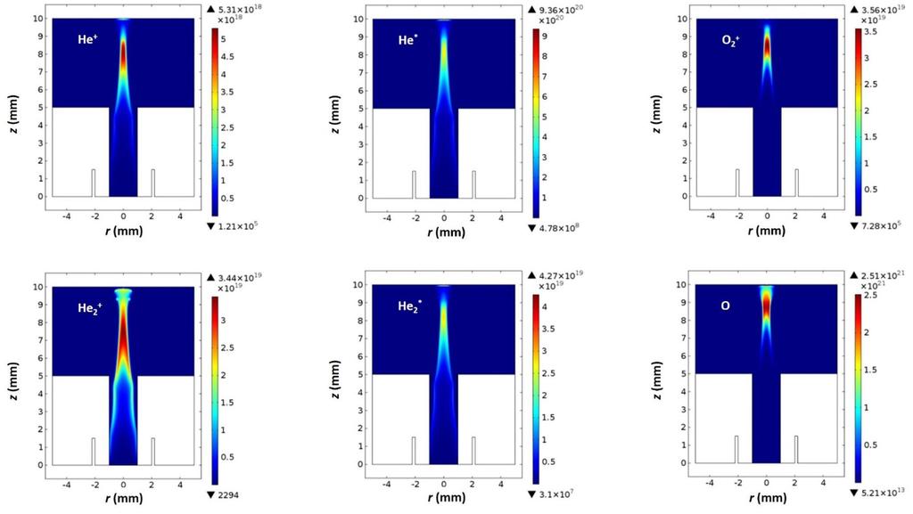
18 E/N and average electron energy (or equivalent electron temperature) can be found by solving the Boltzmann equation. The region next to the substrate is non-local, e.g., the peak E is at the substrate but the peak T e is a bit removed from the substrate. Figure 5 also shows that the peak electric field and electron temperature are found at the plasma bullet head. As the bullet approaches the conductive substrate, the axial electric field and electron temperature at the head both increase. At t = 50 ns, the peak electric field and electron temperature are 148 kv/cm and 25 ev, respectively. After the bullet strikes the substrate, the electric field and electron temperature decrease rapidly. The electric field switches sign from positive to negative near the end (t = 150 ns) of the pulse. This is due to residual charges on the inner surface of the dielectric tube 40 which now plays the role of cathode, while the substrate switches role from cathode to anode. This reverse electric field accelerates electrons towards the substrate, igniting a backward discharge albeit for only a short time. Electron heating by this field is seen close to the substrate in Fig. 5 (green line). Figure 5. Axial electric field (a), and electron temperature (b), along the axis of symmetry for several times during a voltage pulse. Parameters were at their base case values. Figure 6 shows the calculated spatial distribution of species densities at t = 110 ns. He + is generated mainly in the streamer head by electron impact ionization of He and at a lower 18
, the density of He + 2 has a similar spatial profile as He +. The He + 2 density is one order of magnitude higher than the He + density.")
19 rate in the plasma channel upstream of the head by reaction (R4). The peak value of He + density is m -3. Since He + is quickly turned into He 2 + by reaction (R9), the density of He + 2 has a similar spatial profile as He +. The He + 2 density is one order of magnitude higher than the He + density. Metastable He * (peak density m -3 ) has the same spatial profile as the excimer He * 2 (peak density m -3 ). The dominant ion is O + 2, albeit its density is a bit lower than the sum of the He + and He + 2 densities. The peak O-atom density is m -3, commensurate with measurements 14, implying that the plasma jet is a good source of reactive O radicals. Figure 6. Spatial distribution of species densities at 110 ns. Parameters were at their base case values. A significant advantage of the plasma jet is its ability to deliver high fluxes of reactive species to a surface under treatment. Figs. 7(a) and 7(b) show the radial distribution of the flux of neutrals and ions onto a conductive substrate at time t = 110 ns. The fluxes peak on 19
20 the axis of symmetry and plasma-surface interaction occurs primarily within only a 1 mm radius. The flux of neutral species is lower than the positive ion flux, since the only driving force for neutrals is diffusion, while ions are also under the influence of the electric field. The He * and O fluxes are dominant among the neutral species. For positive ions, the He + flux dominates, due to the high mobility of these ions. Negative ions cannot strike the substrate as long as the sheath repels them. However, near the end of the pulse, the electric field reverses and negative ions (as well as accelerated electrons) can strike the surface. The radial flux distribution of O - 2 at t = 150 ns is shown in Fig. 7(c). O - 2 has a similar flux distribution to that of other species, with a peak flux ~ m -2 s -1. Figure 7. Flux of (a) neutrals at t = 110 ns, (b) positive ions at t = 110 ns, and (c) O 2 - negative ions at t = 150 ns on the conductive substrate. Parameters were at their base case values. 20
21 Effect of gap size - In this subsection, the effect of decreasing the gap between the tube exit and the substrate surface from 5 mm to 3 mm is examined. All other parameters were kept at their base case values. The gas flow model yielded the helium mole fraction corresponding to this geometry as shown in Figure 2(b). A smaller gap results in thicker pure helium core, that extends to a larger radial distance along the substrate. The spatial distributions of electron density and electron temperature at t = 35, 45 and 140 ns are shown in Fig. 8. Discharge initiation and propagation in the dielectric tube is hardly affected by the gap size. As the discharge is launched into the helium-oxygen mixing layer, however, the plasma jet diameter is larger in the shorter gap, because the exposure time of the helium jet to the ambient oxygen is shorter, resulting in shorter penetration depth of oxygen into the helium jet. This is also confirmed by experimental observations 20. In addition, the smaller gap results in a shorter propagation time of the streamer from the tube exit to the substrate surface. At about t = 35 ns, the plasma bullet impacts the surface, creating a peak in the electron density (and electron temperature) near the surface. The peak electron temperature is 27.9 ev. After impact, both electron temperature and density near the surface decrease, as electrons flow from ground to neutralize the positive ion flux. Electrons can t strike the substrate in the presence of a positive electric field. The electron density is kept some distance away from the substrate as shown in Fig. 8 at t = 140 ns. A cathode sheath is present, and the electron temperature in the sheath is about 6 ev. 21


22 Figure 8. Spatial profiles of electron density and electron temperature at t = 35 (left panels), 45 (middle panels), and 140 ns (right panels). Parameters were at their base case values except that the gap between the tube exit and the substrate was 3 mm. Rectangular insets show expanded scale of electron density (at t=35 ns), and electron temperature (at t=35 and 45 ns) near the substrate. A comparison of the flux distribution of neutral species and positive ions, on a conductive surface, at time t = 110 ns, for the two gaps is given in Fig. 9. In both cases, the fluxes peak on the axis of symmetry and gradually decrease away from the axis. For the 3 mm gap case, the footprint of the plasma-surface interaction appears larger than that of the 5 mm case. Decreasing the distance between the tube exit and the substrate is therefore desirable to maximize the plasma surface interaction area. However, the peak value of the species flux (especially for O and O + 2 ) decrease as the gap is decreased. The decrease of the O and O + 2 fluxes is mainly due to the lower oxygen mole fraction in the diffusion layer in the shorter gap case (compare figures 2(a) and (b) ). Also, the ionization front residence time is shorter for the smaller gap resulting in less ionization and dissociation. 22
23 Figure 9. Flux of (a) neutrals, and (b) positive ions, onto a conductive substrate at t=110 ns, for 5 mm and 3 mm gap between the jet exit and the substrate surface. Effect of gas pressure- Neglecting buoyancy effects, the fluid mechanics and mass transfer in a laminar jet are controlled by the Reynolds number (Re=uL/ ) and the Peclet number (Pe=uL/D). Here u and L are characteristic gas velocity and length scale, respectively, is kinematic viscosity and D is diffusivity. As pressure decreases, the gas flow velocity increases proportionally, but so do the diffusion coefficient and kinematic viscosity. Thus the Re and Pe numbers remain unchanged, and the results of Fig. 2 (in terms of mole fractions) are valid at the reduced pressures as well. When varying pressure, all other parameters were kept at their base case values (Table 4). The spatial distributions of electron density and electron temperature at t = 20, 35, 140 ns for a gas pressure is 500 Torr are shown in Fig. 10. When compared to the corresponding Fig. 4 for 760 Torr, one observes that the discharge is initiated earlier at the reduced pressure. This may be attributed to the breakdown voltage of helium decreasing by reducing pressure (right branch of the Paschen curve). Also, the average propagation velocity of the plasma bullet increases from m/s at 760 Torr to m/s when pressure is reduced to 500 Torr. A lower pressure results in higher electron temperature in the head of the plasma bullet, leading to higher propagation velocity. 23

24 Figure 10. Spatial profiles of electron density and electron temperature at t = 20 (left panels), 35 (middle panels), and 140 ns (right panels). Parameters were at their base case values except that the gas pressure was 500 Torr. Fig. 11 shows the radial flux distribution of neutral species and positive ions on the conductor surface, at time t = 110 ns for p = 500 and 250 Torr. This is to be compared to Fig. 7 at 760 Torr. In going from 760 to 250 Torr, the plasma surface interaction area increases from ~1 mm to ~2 mm radius, but the peak value of the species flux decreases. The O flux dominates among the minority neutral species. At 500 Torr, the peak of the O-atom flux is near the axis, but at 250 Torr, the peak of O flux is ~ 1 mm off axis. 24
25 Figure 11. Flux of (a) neutrals, and (b) positive ions, onto a conductive substrate, at t=110 ns, for different gas pressures. 3.3 Insulating substrate In this subsection, the effect of insulating substrate is studied by placing a 0.5 mm-thick dielectric layer (relative permittivity of 5) on a grounded conductor. All other parameters were kept constant. The plasma bullet evolution with a dielectric substrate (Fig. 3b) is similar to that with a conductive substrate up to t ~ 35 ns, when the plasma bullet is near the surface. Upon striking the insulating surface, the streamer spreads radially outwards, while ionization and dissociation reactions continue to occur. Eventually, this radially directed surface ionization wave, produced by radial electric fields due to substrate charging 19 is suppressed as in the case of conductive substrate. Fig. 12 shows the distribution of electron density and electron temperature at t = 35, 60 and 140 ns. The dynamics of discharge ignition and propagation inside the dielectric tube, and across most of the gap outside the tube, is hardly affected by the electrical properties of the substrate. After the plasma bullet contacts the substrate, however, charge-up of the insulator causes the plasma bullet to spread along the dielectric surface to a radius of 2 mm. This result is in agreement with Ref. 18. Note that, when the substrate is conductive, the 25
, the electron temperature in the ionization front decreases from 16.7 ev to 8.6 ev. Figure 12.")
26 discharge connects to the substrate via a rather concentrated spot, instead of spreading out. This is in agreement with the experimental observations of Ref. 28. During the radial propagation of a surface ionization front (60 ns to 140 ns), the electron temperature in the ionization front decreases from 16.7 ev to 8.6 ev. Figure 12. Spatial distributions of the electron density and electron temperature at t = 35 (left panels), 60 (middle panels), and 140 ns (right panels) for 5 mm gap, and 0.5 mm-thick insulating surface with permittivity of r = 5. To further investigate the interaction of the plasma bullet with an insulating substrate, the axial electric field and electron temperature along the axis of symmetry are shown in Fig. 13, for different times during a pulse. As in the case of Fig. 5, the peak electric field and electron temperature are located at the bullet head. As the bullet approaches the insulator surface, the maximum axial electric field and electron temperature both increase. The bullet impacts the insulator surface at t = 43 ns. As the bullet head strikes, charge is deposited on the surface. 26
27 The accumulated surface charge can create a negative self-induced potential in the gap and a decrease of the electric field. The higher the accumulated surface charge, the weaker the net electric field. Thus, for time t = 50 ns, the peak electric field and electron temperature on axis close to the wall are only 30 kv/cm and 8 ev, respectively, much lower than the case with a conductive substrate. As mentioned above, during the voltage decay of the pulse (t = ns), a secondary discharge is induced by the charges deposited on the surface of the insulator, much like a dielectric barrier discharge. During this time period the electron temperature increases as electrons are accelerated towards the surface. Effect of relative permittivity - Figure 14 shows the radial flux distributions of neutral species and positive ions on the insulator surface, at time t = 110 ns for ε r = 5 and ε r = 15. In both cases, the peak of species flux is some distance from the axis of symmetry (hollow profiles). Chemistry occurring during the radial propagation of a surface ionization front in the case of the insulating substrate contributes to the off-axis maxima. The O-atoms dominate the neutral species flux, while He + and O + 2 dominate the positive ion flux. For ε r = 5, the footprint of plasma-surface interaction appears larger compared to ε r = 15. This is due to increasing bullet speed with decreasing ε r as the ionization front propagates along the dielectric substrate. As the discharge spreads to larger radii on the surface, its intensity decreases due to progressively higher oxygen mole fraction. In addition, as shown in Figure 14, ε r = 5 yields lower species fluxes, compared to ε r = 15. This is because decreasing ε r results in lower electric field over the dielectric surface after the bullet impacts the surface 41,42. 27
28 Figure 13. Axial profiles of electric field (a), and electron temperature (b), on the axis of symmetry (r = 0) for several times during a pulse, for 5 mm gap, and 0.5 mm-thick insulating surface with permittivity of r = 5.. Figure 14. Flux of (a) neutrals, and (b) positively charged ions onto a 0.5 mm thick insulating surface at t=110 ns for ε r = 5 and ε r = 15. Effect of gas pressure- As discussed above, the plasma bullet evolution with a dielectric substrate is similar to that with a conductive substrate except when the bullet is near the surface. Therefore, emphasis was placed on the influence of pressure on the distributions of species flux onto the insulator surface. Figure 15 shows the radial flux distributions of neutral species and positive ions on the insulator surface, at time t = 110 ns for p = 500 Torr and p = 250 Torr. Lowering the pressure from atmospheric to 250 Torr, the plasma surface interaction radius increases from about 1 mm to 3 mm, but the peak value of the species flux (except O 2 + ) decreases. The O-atoms dominate the neutral species flux at 500 Torr, and the peaks of the 28
29 helium excited state (He * and He * 2 ) fluxes move toward the axis as the pressure decreases, eventually resulting in peak helium metastable on axis at pressure 250 Torr. For both pressures, the peak of positive ion flux is some distance from the axis of symmetry (hollow profiles). The dominant positive ion flux to the surface changes from He + 2 to O + 2 when the pressure decreases from 500 to 250 Torr. Figure 15. Flux of (a) neutrals, and (b) positive ions, onto a 0.5 mm thick insulating surface at t=110 ns, for two different gas pressures. 4. SUMMARY AND CONCLUSIONS A computational investigation of the plasma bullet resulting from a cold plasma jet in helium, flowing inside a dielectric tube and then emerging in oxygen ambient at high pressures ( Torr) was conducted, based on a two-dimensional fluid model. Neutral gas flow and mass transport as well as plasma dynamics were included in the model. Emphasis was placed on the interaction of the plasma bullet with a substrate, for different electrical properties of the substrate (e.g., conductor vs. insulator). The effect of gap between the tube exit and the substrate, relative permittivity of the insulating substrate and gas pressure, on the discharge properties was also studied. The spatiotemporal evolution of the discharge during a 150 ns, +5 kv trapezoidal pulse (10 ns each for rise and fall times) applied 29
30 to a ring electrode encircling the dielectric tube was analyzed. The discharge was initiated at the downstream edge of the ring electrode. Inside the dielectric tube the discharge started as a surface wave along the wall of the tube. A plasma bullet (streamer) was then formed that was launched in the free space between the tube end and the substrate. The bullet was donut-shaped (ionization peaked off axis) upon exiting the tube, but ionization peaked on axis further downstream. Upon impact on a metal (conductive) substrate, the bullet established a conductive channel to the substrate. The species flux to a conductive substrate peaked on axis and decreased rapidly in the radial direction along the surface. The peak positive ion flux was ~ m -2 s -1. The dominant positive ion and neutral species fluxes to the surface were He +, He * and O, respectively. When the gap between the tube exit and the substrate surface was reduced from 5 mm to 3 mm the bullet-surface interaction area increased, while the peak species flux decreased, mainly for O and O + 2. For an electrically insulating substrate, the discharge spread along the radius of the dielectric surface. Species continued to be produced by a surface ionization wave as it propagated along the radius. As a consequence, the species flux peaked off-axis. The dominant ion fluxes were those of He + and O + 2, whereas the O-atom flux was dominant among the neutral species. The plasma-surface interaction area increased when the relative permittivity of the insulator decreased. The propagation velocity of the plasma bullet and the area of direct interaction between the bullet and the substrate both increased by reducing pressure. For insulating substrate, the dominant positive ion flux to the surface changed from He + 2 to O + 2 when the 30
31 pressure decreased from 500 Torr to 250 Torr. Lower pressure favored larger radial displacement of the peak of the positive ion fluxes. A reverse electric field developed during the late stages of the ramp-down of the pulse, which accelerated electrons forming a brief backward discharge. Acknowledgments This work was supported by the Department of Energy, Office of Fusion Energy Science, contract DE-SC Wen Yan is grateful to the National Natural Science Foundation of China for a study abroad grant. 31
32 References 1 M. Laroussi and T. Akan, Plasma Process. Polym. 4, 777 (2007). 2 M.G. Kong, G. Kroesen, G. Morfill, T. Nosenko, T. Shimizu, J. Van Dijk, and J.L. Zimmermann, New J. Phys. 11, (2009). 3 J. Schlegel, J. Köritzer, and V. Boxhammer, Clin. Plasma Med. 1, 2 (2013). 4 X. Zhang and S. Ptasinska, J. Phys. D: Appl. Phys. 47, (2014). 5 D.B. Graves, Phys. Plasmas 21, (2014). 6 H. Paetzelt, G. Böhm, and T. Arnold, Plasma Sources Sci. Technol. 24, (2015). 7 X. Lu, M. Laroussi, and V. Puech, Plasma Sources Sci. Technol. 21, (2012). 8 X. Lu, G. V. Naidis, M. Laroussi, and K. Ostrikov, Phys. Rep. 540, 123 (2014). 9 M. Teschke, J. Kedzierski, E.G. Finantu-Dinu, D. Korzec, and J. Engemann, IEEE Trans. Plasma Sci. 33, 310 (2005). 10 X. Lu and M. Laroussi, J. Appl. Phys. 100, (2006). 11 N. Mericam-Bourdet, M. Laroussi, a Begum, and E. Karakas, J. Phys. D: Appl. Phys. 42, (2009). 12 Y. Sakiyama, D.B. Graves, J. Jarrige, and M. Laroussi, Appl. Phys. Lett. 96, (2010). 13 S. Park, W. Choe, H. Kim, and J.Y. Park, Plasma Sources Sci. Technol. 24, (2015). 14 J.B. Schmidt, B.L. Sands, W.D. Kulatilaka, S. Roy, J. Scofield, and J.R. Gord, Plasma Sources Sci. Technol. 24, (2015). 15 G. V Naidis, J. Phys. D: Appl. Phys. 44, (2011). 16 G. V Naidis, IEEE Trans. Plasma Sci. 43, 733 (2015). 17 D. Breden, K. Miki, and L.L. Raja, Plasma Sources Sci. Technol. 21, (2012). 18 D. Breden and L.L. Raja, Plasma Sources Sci. Technol. 23, (2014). 19 S. A. Norberg, E. Johnsen, and M.J. Kushner, J. Appl. Phys. 118, (2015). 32
33 20 Y. Xian, P. Zhang, X. Pei, and X. Lu, IEEE Trans. Plasma Sci. 42, 2448 (2014). 21 A. Schmidt-Bleker, S. A Norberg, J. Winter, E. Johnsen, S. Reuter, K.D. Weltmann, and M.J. Kushner, Plasma Sources Sci. Technol. 24, (2015). 22 J. Winter, J.S. Sousa, N. Sadeghi, a Schmidt-Bleker, S. Reuter, and V. Puech, Plasma Sources Sci. Technol. 24, (2015). 23 D.X. Liu, M.Z. Rong, X.H. Wang, F. Iza, M.G. Kong, and P. Bruggeman, Plasma Process. Polym. 7, 846 (2010). 24 G.Y. Park, Y.J. Hong, H.W. Lee, J.Y. Sim, and J.K. Lee, Plasma Process. Polym. 7, 281 (2010). 25 J. He and Y.T. Zhang, Plasma Process. Polym. 9, 919 (2012). 26 X.Y. Liu, X.K. Pei, X.P. Lu, and D.W. Liu, Plasma Sources Sci. Technol. 23, (2014). 27 X. Lu, Z. Jiang, Q. Xiong, Z. Tang, and Y. Pan, Appl. Phys. Lett. 92, (2008). 28 J.L. Walsh, J.J. Shi, and M.G. Kong, Appl. Phys. Lett. 88, (2006). 29 X. Shao, Z. Chang, and H. Mu, W. Liao, and G. Zhang, IEEE Trans. Plasma Sci. 41, 899 (2013) COMSOL 5.0 (Burlington, MA: COMSOL). 31 W. Yan, F. Liu, C. Sang, and D. Wang, Phys. Plasmas 21, (2014). 32 W. Yan, F. Liu, C. Sang, and D. Wang, Phys. Plasmas 21, (2014). 33 Y. Sakiyama and D.B. Graves, Plasma Sources Sci. Technol. 18, (2009). 34 G. Hagelaar and L. Pitchford, Plasma Sources Sci. Technol. 14, 722 (2005). 35 See for cross section data. 36 Q. Wang, D.J. Economou, and V.M. Donnelly, J. Appl. Phys. 100, (2006). 37 D.S. Stafford and M.J. Kushner, J. Appl. Phys. 96, 2451 (2004). 38 D. Breden, K. Miki, and L.L. Raja, Appl. Phys. Lett. 99, (2011). 39 J.P. Boeuf, L.L. Yang, and L.C. Pitchford, J. Phys. D: Appl. Phys. 46, (2013). 33
34 40 S. Hübner, S. Hofmann, E.M. van Veldhuizen, and P.J. Bruggeman, Plasma Sources Sci. Technol. 22, (2013). 41 F. Pechereau, J. Jánský, and A. Bourdon, Plasma Sources Sci. Technol. 21, (2012). 42 N.Y. Babaeva and M.J. Kushner, Plasma Sources Sci. Technol. 20, (2011). 34
35

36
37
38

39
40
41
42
43
44
45
46
47
48
49
50
51
52

53
54
55
56
57
58
59
PIC/MCC Simulation of Radio Frequency Hollow Cathode Discharge in Nitrogen
 PIC/MCC Simulation of Radio Frequency Hollow Cathode Discharge in Nitrogen HAN Qing ( ), WANG Jing ( ), ZHANG Lianzhu ( ) College of Physics Science and Information Engineering, Hebei Normal University,
Influence of helium mole fraction distribution on the properties of cold atmospheric pressure helium plasma jets
 Influence of helium mole fraction distribution on the properties of cold atmospheric pressure helium plasma jets Ranhua Xiong 1, Qing Xiong 1, 2, Anton Yu. Nikiforov 1, Patrick Vanraes 1, and Christophe
Electric Field Measurements in Atmospheric Pressure Electric Discharges
 70 th Gaseous Electronics Conference Pittsburgh, PA, November 6-10, 2017 Electric Field Measurements in Atmospheric Pressure Electric Discharges M. Simeni Simeni, B.M. Goldberg, E. Baratte, C. Zhang, K.
Generation and loss of reactive oxygen species in low-temperature atmospheric-pressure RF He + O2 + H2O plasmas
 Loughborough University Institutional Repository Generation and loss of reactive oxygen species in low-temperature atmospheric-pressure RF He + O2 + H2O plasmas This item was submitted to Loughborough
Simulation of a two-dimensional sheath over a flat wall with an insulatorõconductor interface exposed to a high density plasma
 JOURNAL OF APPLIED PHYSICS VOLUME 94, NUMBER 5 1 SEPTEMBER 2003 Simulation of a two-dimensional sheath over a flat wall with an insulatorõconductor interface exposed to a high density plasma Doosik Kim
Two-dimensional Numerical Simulation of a Planar Radio-frequency Atmospheric Pressure Plasma Source
 Two-dimensional Numerical Simulation of a Planar Radio-frequency Atmospheric Pressure Plasma Source Lei Wang 1*, Gheorghe Dscu, Eusebiu-Rosini Ionita, Christophe Leys 1, Anton Yu Nikiforov 1 1 Department
Role of confinement in the development of a helium impacting plasma jet at atmospheric pressure
 Role of confinement in the development of a helium impacting plasma jet at atmospheric pressure T. Gaudy 1,2, J. Iacono 1, A. Toutant 1, P. Descamps 2, P Leempoel 2, F. Massines 1 1 : Laboratoire PROcédés,
MICRODISCHARGES AS SOURCES OF PHOTONS, RADICALS AND THRUST*
 MICRODISCHARGES AS SOURCES OF PHOTONS, RADICALS AND THRUST* Ramesh Arakoni a) and Mark J. Kushner b) a) Dept. Aerospace Engineering b) Dept. Electrical and Computer Engineering Urbana, IL 61801 USA mjk@uiuc.edu
Formation of white-eye pattern with microdischarge in an air. dielectric barrier discharge system
 Formation of white-eye pattern with microdischarge in an air dielectric barrier discharge system Yafeng He, Lifang Dong*, Weili Liu, Hongfang Wang, Zengchao Zhao, and Weili Fan College of Physics Science
Current sheath formation in the plasma focus
 Plasma Science and Applications (ICPSA 2013) International Journal of Modern Physics: Conference Series Vol. 32 (2014) 1460321 (8 pages) The Author DOI: 10.1142/S2010194514603214 Current sheath formation
Numerical Simulation of Atmospheric-pressure Non-equilibrium Plasmas: Status and Prospects
 104 International Journal of Plasma Environmental Science & Technology, Vol.7, No.2, JULY 2013 Numerical Simulation of Atmospheric-pressure Non-equilibrium Plasmas: Status and Prospects W. S. Kang 1, M.
Modeling and Simulation of Plasma-Assisted Ignition and Combustion
 Modeling and Simulation of Plasma-Assisted Ignition and Combustion Vigor Yang and Sharath Nagaraja Georgia Institute of Technology Atlanta, GA AFOSR MURI Fundamental Mechanisms, Predictive Modeling, and
Modeling plasma-based CO 2 conversion: From chemistry to plasma design
 Modeling plasma-based CO 2 conversion: From chemistry to plasma design Annemie Bogaerts T. Kozak, R. Snoeckx, G. Trenchev, K. Van Laer Research group PLASMANT, University of Antwerp, Belgium CO 2 + CH
Investigation of Nanosecond-pulsed Dielectric Barrier Discharge Actuators with Powered. Electrode of Different Exposures
 Plasma Science and Technology, Volume 19, Number 9 http://iopscience.iop.org/article/10.1088/2058-6272/aa6f59/meta Investigation of Nanosecond-pulsed Dielectric Barrier Discharge Actuators with Powered
The Effect of Discharge Characteristics on Dielectric Barrier Discharges According to the Relative Permittivity
 , pp.21-27 http://dx.doi.org/10.14257/astl.2017.145.05 The Effect of Discharge Characteristics on Dielectric Barrier Discharges According to the Relative Permittivity Don-Kyu Lee Electrical Engineering,
SCALING OF PLASMA SOURCES FOR O 2 ( 1 ) GENERATION FOR CHEMICAL OXYGEN-IODINE LASERS
 GENERATION FOR CHEMICAL OXYGEN-IODINE LASERS") SCALING OF PLASMA SOURCES FOR O 2 ( 1 ) GENERATION FOR CHEMICAL OXYGEN-IODINE LASERS D. Shane Stafford and Mark J. Kushner Department of Electrical and Computer Engineering Urbana, IL 61801 http://uigelz.ece.uiuc.edu
SCALING OF PLASMA SOURCES FOR O 2 ( 1 ) GENERATION FOR CHEMICAL OXYGEN-IODINE LASERS D. Shane Stafford and Mark J. Kushner Department of Electrical and Computer Engineering Urbana, IL 61801 http://uigelz.ece.uiuc.edu
Numerical Simulation of Townsend Discharge, Paschen Breakdown and Dielectric Barrier Discharges Napoleon Leoni, Bhooshan Paradkar
 Numerical Simulation of Townsend Discharge, Paschen Breakdown and Dielectric Barrier Discharges Napoleon Leoni, Bhooshan Paradkar HP Laboratories HPL-2009-234 Keyword(s): Townsend Discharge, Paschen Breakdown,
arxiv: v1 [physics.plasm-ph] 10 Nov 2014
![arxiv: v1 [physics.plasm-ph] 10 Nov 2014](/thumbs/88/117240344.jpg "arxiv: v1 [physics.plasm-ph] 10 Nov 2014") arxiv:1411.2464v1 [physics.plasm-ph] 10 Nov 2014 Effects of fast atoms and energy-dependent secondary electron emission yields in PIC/MCC simulations of capacitively coupled plasmas A. Derzsi 1, I. Korolov
arxiv:1411.2464v1 [physics.plasm-ph] 10 Nov 2014 Effects of fast atoms and energy-dependent secondary electron emission yields in PIC/MCC simulations of capacitively coupled plasmas A. Derzsi 1, I. Korolov
One dimensional hybrid Maxwell-Boltzmann model of shearth evolution
 Technical collection One dimensional hybrid Maxwell-Boltzmann model of shearth evolution 27 - Conferences publications P. Sarrailh L. Garrigues G. J. M. Hagelaar J. P. Boeuf G. Sandolache S. Rowe B. Jusselin
Modeling and Simulation of Plasma-Assisted Ignition and Combustion
 Modeling and Simulation of Plasma-Assisted Ignition and Combustion Sharath Nagaraja and Vigor Yang Georgia Institute of Technology Atlanta, GA 30332-0150 AFOSR MURI Fundamental Mechanisms, Predictive Modeling,
FLASH CHAMBER OF A QUASI-CONTINUOUS VOLUME SOURCE OF NEGATIVE IONS
 FLASH CHAMBER OF A QUASI-CONTINUOUS VOLUME SOURCE OF NEGATIVE IONS P.A. Litvinov, V.A. Baturin * Institute of Applied Physics, National Academy of Science of Ukraine, 58 Petropavlovskaya St. Sumy, 40030
Simulation of a two-dimensional sheath over a flat insulator conductor interface on a radio-frequency biased electrode in a high-density plasma
 JOURNAL OF APPLIED PHYSICS VOLUME 95, NUMBER 7 1 APRIL 2004 Simulation of a two-dimensional sheath over a flat insulator conductor interface on a radio-frequency biased electrode in a high-density plasma
PIC-MCC/Fluid Hybrid Model for Low Pressure Capacitively Coupled O 2 Plasma
 PIC-MCC/Fluid Hybrid Model for Low Pressure Capacitively Coupled O 2 Plasma Kallol Bera a, Shahid Rauf a and Ken Collins a a Applied Materials, Inc. 974 E. Arques Ave., M/S 81517, Sunnyvale, CA 9485, USA
Extremely far from equilibrium: the multiscale dynamics of streamer discharges
 Extremely far from equilibrium: the multiscale dynamics of streamer discharges Ute Ebert 1,2 1 Centrum Wiskunde & Informatica Amsterdam 2 Eindhoven University of Technology http://www.cwi.nl/~ebert www.cwi.nl/~ebert
4 Modeling of a capacitive RF discharge
 4 Modeling of a capacitive discharge 4.1 PIC MCC model for capacitive discharge Capacitive radio frequency () discharges are very popular, both in laboratory research for the production of low-temperature
Multidimensional Numerical Simulation of Glow Discharge by Using the N-BEE-Time Splitting Method
 Plasma Science and Technology, Vol.14, No.9, Sep. 2012 Multidimensional Numerical Simulation of Glow Discharge by Using the N-BEE-Time Splitting Method Benyssaad KRALOUA, Ali HENNAD Electrical Engineering
Numerical Study on Influences of Barrier Arrangements on Dielectric Barrier Discharge Characteristics
 504 IEEE TRANSACTIONS ON PLASMA SCIENCE, VOL. 31, NO. 4, AUGUST 2003 Numerical Study on Influences of Barrier Arrangements on Dielectric Barrier Discharge Characteristics Woo Seok Kang, Jin Myung Park,
Numerical Simulation of Fluid Flow and Heat Transfer in a Plasma Cutting Torch
 Numerical Simulation of Fluid Flow and Heat Transfer in a Plasma Cutting Torch ASAD A.SALEM College of Science & Technology Texas A&M University- Corpus Christi Corpus Christi, TX 78412-5797 USA Abstract:
PIC-MCC/Fluid Hybrid Model for Low Pressure Capacitively Coupled O 2 Plasma
 PIC-MCC/Fluid Hybrid Model for Low Pressure Capacitively Coupled O 2 Plasma Kallol Bera a, Shahid Rauf a and Ken Collins a a Applied Materials, Inc. 974 E. Arques Ave., M/S 81517, Sunnyvale, CA 9485, USA
Modeling nonthermal plasmas generated in glow discharges*
 Pure Appl. Chem., Vol. 71, No. 10, pp. 1837±1844, 1999. Printed in Great Britain. q 1999 IUPAC Modeling nonthermal plasmas generated in glow discharges* I. Revel, Ph. Belenguer, J. P. Boeuf and L. C. Pitchford²
Ionization Detectors. Mostly Gaseous Detectors
 Ionization Detectors Mostly Gaseous Detectors Introduction Ionization detectors were the first electrical devices developed for radiation detection During the first half of the century: 3 basic types of
Electron Current Extraction and Interaction of RF mdbd Arrays
 Electron Current Extraction and Interaction of RF mdbd Arrays Jun-Chieh Wang a), Napoleon Leoni b), Henryk Birecki b), Omer Gila b), and Mark J. Kushner a) a), Ann Arbor, MI 48109 USA mkush@umich.edu,
Plasma Formation in the Near Anode Region in Hall Thrusters
 41st AIAA/ASME/SAE/ASEE Joint Propulsion Conference & Exhibit 10-13 July 2005, Tucson, Arizona AIAA 2005-4059 41 st AIAA/ASME/SAE/ASEE Joint Propulsion Conference & Exhibit AIAA-2005-4059 Plasma Formation
Transition of laminar pre-mixed flames to turbulence - induced by sub-breakdown applied voltage
 Transition of laminar pre-mixed flames to turbulence - induced by sub-breakdown applied voltage Biswa N. Ganguly Aerospace Systems Directorate, Air Force Research Laboratory WPAFB OH USA and Jacob Schmidt
Matti Laan Gas Discharge Laboratory University of Tartu ESTONIA
 Matti Laan Gas Discharge Laboratory University of Tartu ESTONIA Outline 1. Ionisation 2. Plasma definition 3. Plasma properties 4. Plasma classification 5. Energy transfer in non-equilibrium plasma 6.
Multiple microdischarge dynamics in dielectric barrier discharges
 JOURNAL OF APPLIED PHYSICS VOLUME 84, NUMBER 8 15 OCTOBER 1998 Multiple microdischarge dynamics in dielectric barrier discharges Xudong Peter Xu a) and Mark J. Kushner b) University of Illinois, Department
Nonequilibrium discharges in air and nitrogen plasmas at atmospheric pressure*
 Pure Appl. Chem., Vol. 74, No. 3, pp. 337 347, 2002. 2002 IUPAC Nonequilibrium discharges in air and nitrogen plasmas at atmospheric pressure* Charles H. Kruger, Christophe O. Laux, Lan Yu, Denis M. Packan,
A KINETIC MODEL FOR EXCIMER UV AND VUV RADIATION IN DIELECTRIC BARRIER DISCHARGES*
 A KINETIC MODEL FOR EXCIMER UV AND VUV RADIATION IN DIELECTRIC BARRIER DISCHARGES* Xudong Peter Xu and Mark J. Kushner University of Illinois Department of Electrical and Computer Engineering Urbana, IL
Numerical studies on the breakdown process in gas discharges
 Eindhoven University of Technology Department of Applied Physics Group of Elementary Processes in Gas Discharges Numerical studies on the breakdown process in gas discharges P. Verhoeven EPG 12-04 March
arxiv: v2 [physics.plasm-ph] 31 May 2013
![arxiv: v2 [physics.plasm-ph] 31 May 2013](/thumbs/81/84711493.jpg "arxiv: v2 [physics.plasm-ph] 31 May 2013") arxiv:128.6519v2 [physics.plasm-ph] 31 May 213 Ionization by bulk heating of electrons in capacitive radio frequency atmospheric pressure microplasmas T Hemke 1, D Eremin 1, T Mussenbrock 1, A Derzsi 2,
arxiv:128.6519v2 [physics.plasm-ph] 31 May 213 Ionization by bulk heating of electrons in capacitive radio frequency atmospheric pressure microplasmas T Hemke 1, D Eremin 1, T Mussenbrock 1, A Derzsi 2,
Chapiter VII: Ionization chamber
 Chapiter VII: Ionization chamber 1 Types of ionization chambers Sensitive volume: gas (most often air direct measurement of exposure) ionization chamber Sensitive volume: semiconductor (silicon, germanium,
Electric Potential Energy & Voltage. Tesla Envy =jlzeqz4efqa&feature=related
 Electric Potential Energy & Voltage Tesla Envy http://www.youtube.com/watch?v =jlzeqz4efqa&feature=related Ch 23 & 24: Electric Force and Field F qq k r 1 2rˆ 12 2 F qe kq Electric Field E due to q : E
Numerical simulation of Vibrationally Active Ar-H2 Microwave Plasma
 Numerical simulation of Vibrationally Active Ar-H2 Microwave Plasma F. Bosi 1, M. Magarotto 2, P. de Carlo 2, M. Manente 2, F. Trezzolani 2, D. Pavarin 2, D. Melazzi 2, P. Alotto 1, R. Bertani 1 1 Department
Diagnostics on an atmospheric pressure plasma jet
 Diagnostics on an atmospheric pressure plasma jet Niemi, K., St, R., Schaper, L., Knake, N., Schulz-von Der Gathen, V., & Gans, T. (2007). Diagnostics on an atmospheric pressure plasma jet. Journal of
Low Temperature Plasma Technology Laboratory
 Low Temperature Plasma Technology Laboratory CENTRAL PEAKING OF MAGNETIZED GAS DISCHARGES Francis F. Chen and Davide Curreli LTP-1210 Oct. 2012 Electrical Engineering Department Los Angeles, California
Plasma Modeling with COMSOL Multiphysics
 Plasma Modeling with COMSOL Multiphysics Copyright 2014 COMSOL. Any of the images, text, and equations here may be copied and modified for your own internal use. All trademarks are the property of their
MAGNETIC NOZZLE PLASMA EXHAUST SIMULATION FOR THE VASIMR ADVANCED PROPULSION CONCEPT
 MAGNETIC NOZZLE PLASMA EXHAUST SIMULATION FOR THE VASIMR ADVANCED PROPULSION CONCEPT ABSTRACT A. G. Tarditi and J. V. Shebalin Advanced Space Propulsion Laboratory NASA Johnson Space Center Houston, TX
The Franck-Hertz Experiment Physics 2150 Experiment No. 9 University of Colorado
 Experiment 9 1 Introduction The Franck-Hertz Experiment Physics 2150 Experiment No. 9 University of Colorado During the late nineteenth century, a great deal of evidence accumulated indicating that radiation
Adjustment of electron temperature in ECR microwave plasma
 Vacuum (3) 53 Adjustment of electron temperature in ECR microwave plasma Ru-Juan Zhan a, Xiaohui Wen a,b, *, Xiaodong Zhu a,b, Aidi zhao a,b a Structure Research Laboratory, University of Science and Technology
Modeling of a DBD Reactor for the Treatment of VOC
 Excerpt from the Proceedings of the COMSOL Conference 2009 Milan Modeling of a DBD Reactor for the Treatment of VOC Lamia Braci, Stephanie Ognier, and Simeon Cavadias* Laboratoire de Génie des Procédés
Numerical Simulation: Effects of Gas Flow and Rf Current Direction on Plasma Uniformity in an ICP Dry Etcher
 Appl. Sci. Converg. Technol. 26(6): 189-194 (2017) http://dx.doi.org/10.5757/asct.2017.26.6.189 Research Paper Numerical Simulation: Effects of Gas Flow and Rf Current Direction on Plasma Uniformity in
Chapter 4 Scintillation Detectors
 Med Phys 4RA3, 4RB3/6R03 Radioisotopes and Radiation Methodology 4-1 4.1. Basic principle of the scintillator Chapter 4 Scintillation Detectors Scintillator Light sensor Ionizing radiation Light (visible,
Huashun Zhang. Ion Sources. With 187 Figures and 26 Tables Э SCIENCE PRESS. Springer
 Huashun Zhang Ion Sources With 187 Figures and 26 Tables Э SCIENCE PRESS Springer XI Contents 1 INTRODUCTION 1 1.1 Major Applications and Requirements 1 1.2 Performances and Research Subjects 1 1.3 Historical
Lecture 6: High Voltage Gas Switches
 Lecture 6: High Voltage Gas Switches Switching is a central problem in high voltage pulse generation. We need fast switches to generate pulses, but in our case, they must also hold off high voltages before
DOE WEB SEMINAR,
 DOE WEB SEMINAR, 2013.03.29 Electron energy distribution function of the plasma in the presence of both capacitive field and inductive field : from electron heating to plasma processing control 1 mm PR
Helicon Plasma Thruster Experiment Controlling Cross-Field Diffusion within a Magnetic Nozzle
 Helicon Plasma Thruster Experiment Controlling Cross-Field Diffusion within a Magnetic Nozzle IEPC-2013-163 Presented at the 33rd International Electric Propulsion Conference, The George Washington University
MAPPING OF ATOMIC NITROGEN IN SINGLE FILAMENTS OF A BARRIER DISCHARGE MEASURED BY TWO PHOTON FLUORESCENCE SPECTROSCOPY (TALIF)
") MAPPING OF ATOMIC NITROGEN IN SINGLE FILAMENTS OF A BARRIER DISCHARGE MEASURED BY TWO PHOTON FLUORESCENCE SPECTROSCOPY (TALIF) C. LUKAS, M. SPAAN, V. SCHULZ VON DER GATHEN, H. F. DÖBELE Institut für Laser
MAPPING OF ATOMIC NITROGEN IN SINGLE FILAMENTS OF A BARRIER DISCHARGE MEASURED BY TWO PHOTON FLUORESCENCE SPECTROSCOPY (TALIF) C. LUKAS, M. SPAAN, V. SCHULZ VON DER GATHEN, H. F. DÖBELE Institut für Laser
Measurements of electric-field strengths in ionization fronts during breakdown Wagenaars, E.; Bowden, M.D.; Kroesen, G.M.W.
 Measurements of electric-field strengths in ionization fronts during breakdown Wagenaars, E.; Bowden, M.D.; Kroesen, G.M.W. Published in: Physical Review Letters DOI: 10.1103/PhysRevLett.98.075002 Published:
EE6701 HIGH VOLTAGE ENGINEERING UNIT II-DIELECTRIC BREAKDOWN PART A
 EE6701 HIGH VOLTAGE ENGINEERING UNIT II-DIELECTRIC BREAKDOWN PART A 1. Mention the gases used as the insulating medium in electrical apparatus? Most of the electrical apparatus use air as the insulating
Electrical Discharges Characterization of Planar Sputtering System
 International Journal of Recent Research and Review, Vol. V, March 213 ISSN 2277 8322 Electrical Discharges Characterization of Planar Sputtering System Bahaa T. Chaid 1, Nathera Abass Ali Al-Tememee 2,
Driving frequency effects on the mode transition in capacitively coupled argon discharges
 Driving frequency effects on the mode transition in capacitively coupled argon discharges Liu Xiang-Mei( ), Song Yuan-Hong( ), and Wang You-Nian( ) School of Physics and Optoelectronic Technology, Dalian
O 2 1 production in flowing He/O 2 plasmas. II. Two-dimensional modeling
 JOURNAL OF APPLIED PHYSICS 98, 073304 2005 O 2 1 production in flowing He/O 2 plasmas. II. Two-dimensional modeling Ramesh Arakoni a Department of Aerospace Engineering, University of Illinois, Urbana,
Spatial distributions of power and ion densities in RF excited remote plasma reactors
 Plasma Sources Sci. Technol. 5 (1996) 499 509. Printed in the UK Spatial distributions of power and ion densities in RF excited remote plasma reactors Irène Pérès and Mark J Kushner University of Illinois,
Beams and magnetized plasmas
 Beams and magnetized plasmas 1 Jean-Pierre BOEUF LAboratoire PLAsma et Conversion d Energie LAPLACE/ CNRS, Université Paul SABATIER, TOULOUSE Beams and magnetized plasmas 2 Outline Ion acceleration and
Electrostatics so far
 Electrostatics so far F = 1 2 1 2 2 Electric Force b/n q and q : qq 1 2 kq Electric Field E due to q : E = 1 1 r 2 kq q r q e = 1.6 x10⁻¹⁹ C k = 9 x 10 9 Nm 2 /C 2 Tesla Envy http://www.youtube.com/watch?v=jl
Electron temperature is the temperature that describes, through Maxwell's law, the kinetic energy distribution of the free electrons.
 10.3.1.1 Excitation and radiation of spectra 10.3.1.1.1 Plasmas A plasma of the type occurring in spectrochemical radiation sources may be described as a gas which is at least partly ionized and contains
Characteristics and classification of plasmas
 Characteristics and classification of plasmas PlasTEP trainings course and Summer school 2011 Warsaw/Szczecin Indrek Jõgi, University of Tartu Partfinanced by the European Union (European Regional Development
Department of Aerospace Engineering and Engineering Mechanics, The University of Texas at Austin, Austin, Texas 78712, USA
 1 MAGNETIZED DIRECT CURRENT MICRODISCHARGE, I: EFFECT OF THE GAS PRESSURE Dmitry Levko and Laxminarayan L. Raja Department of Aerospace Engineering and Engineering Mechanics, The University of Texas at
Volume Production of D - Negative Ions in Low-Pressure D 2 Plasmas - Negative Ion Densities versus Plasma Parameters -
 Volume Production of D - Negative Ions in Low-Pressure D 2 Plasmas - Negative Ion Densities versus Plasma Parameters - Osamu Fukumasa and Shigefumi Mori Department of Electrical and Electronic Engineering,
MWP MODELING AND SIMULATION OF ELECTROMAGNETIC EFFECTS IN CAPACITIVE DISCHARGES
 MWP 1.9 MODELING AND SIMULATION OF ELECTROMAGNETIC EFFECTS IN CAPACITIVE DISCHARGES Insook Lee, D.B. Graves, and M.A. Lieberman University of California Berkeley, CA 9472 LiebermanGEC7 1 STANDING WAVES
Physics and Modelling of a Negative Ion Source Prototype for the ITER Neutral Beam Injection
 1 ITR/P1-37 Physics and Modelling of a Negative Ion Source Prototype for the ITER Neutral Beam Injection J.P. Boeuf a, G. Fubiani a, G. Hagelaar a, N. Kohen a, L. Pitchford a, P. Sarrailh a, and A. Simonin
PRINCIPLES OF PLASMA DISCHARGES AND MATERIALS PROCESSING
 PRINCIPLES OF PLASMA DISCHARGES AND MATERIALS PROCESSING Second Edition MICHAEL A. LIEBERMAN ALLAN J, LICHTENBERG WILEY- INTERSCIENCE A JOHN WILEY & SONS, INC PUBLICATION CONTENTS PREFACE xrrii PREFACE
Simulation of Inductively Coupled Plasma of Ar/C2H2/CH4/H2 gas mixture in PECVD reactor and calculating the reactor efficiency
 Simulation of Inductively Coupled Plasma of Ar/C2H2/CH4/H2 gas mixture in PECVD reactor and calculating the reactor efficiency Manish Kumar 1, Sagar Khanna 2, Suresh C Sharma 3 1,2M.Tech Student, Dept.
Multi-fluid Simulation Models for Inductively Coupled Plasma Sources
 Multi-fluid Simulation Models for Inductively Coupled Plasma Sources Madhusudhan Kundrapu, Seth A. Veitzer, Peter H. Stoltz, Kristian R.C. Beckwith Tech-X Corporation, Boulder, CO, USA and Jonathan Smith
MULTIPACTOR ON A DIELECTRIC SURFACE WITH LONGITUDINAL RF ELECTRIC FIELD ACTION
 Progress In Electromagnetics Research Letters, Vol. 24, 177 185, 211 MULTIPACTOR ON A DIELECTRIC SURFACE WITH LONGITUDINAL RF ELECTRIC FIELD ACTION F. Zhu *, Z. Zhang, J. Luo, and S. Dai Key Laboratory
Simulation. Lizhu Tong 1 Co., Ltd Numerical. Model. 1. Introduction. flows. discussed. kinds. the maximum. plasma model.
 Simulation of the Plasma Generated a Gas Bubble Lizhu Tong 1 1 Keisoku Engeerg System Co., Ltd. 1-9-5 Uchikanda, Chiyoda-ku, Tokyo 1-0047, Japan, tong@kesco.co.jp Abstract: The plasmas generated water
Physique des plasmas radiofréquence Pascal Chabert
 Physique des plasmas radiofréquence Pascal Chabert LPP, Ecole Polytechnique pascal.chabert@lpp.polytechnique.fr Planning trois cours : Lundi 30 Janvier: Rappels de physique des plasmas froids Lundi 6 Février:
Adaptive numerical simulation of Streamer. Shailendra Singh
 Adaptive numerical simulation of Streamer Shailendra Singh Tools: BDV from Drift diffusion calculation Motivation: Streamer criteria works very well in moderately uniform field. But in highly non uniform
Relationship between production and extraction of D - /H - negative ions in a volume negative ion source
 J. Plasma Fusion Res. SERIES, Vol. 8 (2009) Relationship between production and extraction of D - /H - negative ions in a volume negative ion source Takahiro Nakano, Shigefumi Mori, Yasushi Tauchi, Wataru
A Magnetohydrodynamic study af a inductive MHD generator
 Excerpt from the Proceedings of the COMSOL Conference 2009 Milan A Magnetohydrodynamic study af a inductive MHD generator Augusto Montisci, Roberto Pintus University of Cagliari, Department of Electrical
Discovered by German scientist Johann Hittorf in 1869 and in 1876 named by Eugen Goldstein.
 DO PHYSICS ONLINE CATHODE RAYS CATHODE RAYS (electron beams) Streams of electrons (negatively charged particles) observed in vacuum tubes - evacuated glass tubes that are equipped with at least two metal
Theoretical analysis of ion kinetic energies and DLC film deposition by CH 4 +Ar (He) dielectric barrier discharge plasmas
 dielectric barrier discharge plasmas") Vol 16 No 9, September 2007 c 2007 Chin. Phys. Soc. 1009-1963/2007/16(09)/2809-05 Chinese Physics and IOP Publishing Ltd Theoretical analysis of ion kinetic energies and DLC film deposition by CH 4 +Ar
Vol 16 No 9, September 2007 c 2007 Chin. Phys. Soc. 1009-1963/2007/16(09)/2809-05 Chinese Physics and IOP Publishing Ltd Theoretical analysis of ion kinetic energies and DLC film deposition by CH 4 +Ar
Lecture 6 Plasmas. Chapters 10 &16 Wolf and Tauber. ECE611 / CHE611 Electronic Materials Processing Fall John Labram 1/68
 Lecture 6 Plasmas Chapters 10 &16 Wolf and Tauber 1/68 Announcements Homework: Homework will be returned to you on Thursday (12 th October). Solutions will be also posted online on Thursday (12 th October)
Modélisation de sources plasma froid magnétisé
 Modélisation de sources plasma froid magnétisé Gerjan Hagelaar Groupe de Recherche Energétique, Plasma & Hors Equilibre (GREPHE) Laboratoire Plasma et Conversion d Énergie (LAPLACE) Université Paul Sabatier,
The low-field density peak in helicon discharges
 PHYSICS OF PLASMAS VOLUME 10, NUMBER 6 JUNE 2003 Francis F. Chen a) Electrical Engineering Department, University of California, Los Angeles, Los Angeles, California 90095-1597 Received 10 December 2002;
Miniaturized Argon Plasma: Neutral Gas Characteristics in Dielectric Barrier Discharge
 Miniaturized Argon Plasma: Neutral Gas Characteristics in Dielectric Barrier Discharge Ashraf FARAHAT 1,2 1 Department of Prep Year Physics, College of Applied and Supporting Studies, King FahdUniversity
Effect of small amounts of hydrogen added to argon glow discharges: Hybrid Monte Carlo fluid model
 PHYSICAL REVIEW E, VOLUME 65, 056402 Effect of small amounts of hydrogen added to argon glow discharges: Hybrid Monte Carlo fluid model Annemie Bogaerts* and Renaat Gijbels Department of Chemistry, University
Introduction to Plasma
 What is a plasma? The fourth state of matter A partially ionized gas How is a plasma created? Energy must be added to a gas in the form of: Heat: Temperatures must be in excess of 4000 O C Radiation Electric
Residual resistance simulation of an air spark gap switch.
 Residual resistance simulation of an air spark gap switch. V. V. Tikhomirov, S.E. Siahlo February 27, 2015 arxiv:1502.07499v1 [physics.acc-ph] 26 Feb 2015 Research Institute for Nuclear Problems, Belarusian
MODELING AND SIMULATION OF LOW TEMPERATURE PLASMA DISCHARGES
 MODELING AND SIMULATION OF LOW TEMPERATURE PLASMA DISCHARGES Michael A. Lieberman University of California, Berkeley lieber@eecs.berkeley.edu DOE Center on Annual Meeting May 2015 Download this talk: http://www.eecs.berkeley.edu/~lieber
Effect of Applied Electric Field and Pressure on the Electron Avalanche Growth
 Effect of Applied Electric Field and Pressure on the Electron Avalanche Growth L. ZEGHICHI (), L. MOKHNACHE (2), and M. DJEBABRA (3) () Department of Physics, Ouargla University, P.O Box.5, OUARGLA 3,
Modeling and Simulation of Plasma Based Applications in the Microwave and RF Frequency Range
 Modeling and Simulation of Plasma Based Applications in the Microwave and RF Frequency Range Dr.-Ing. Frank H. Scharf CST of America What is a plasma? What is a plasma? Often referred to as The fourth
Spatially resolved simulation of a radio-frequency driven micro-atmospheric pressure plasma jet and its effluent
 Spatially resolved simulation of a radio-frequency driven micro-atmospheric pressure plasma jet and its effluent Torben Hemke, Alexander Wollny, Markus Gebhardt, Ralf Peter Brinkmann, Thomas Mussenbrock
MODELING OF AN ECR SOURCE FOR MATERIALS PROCESSING USING A TWO DIMENSIONAL HYBRID PLASMA EQUIPMENT MODEL. Ron L. Kinder and Mark J.
 TECHCON 98 Las Vegas, Nevada September 9-11, 1998 MODELING OF AN ECR SOURCE FOR MATERIALS PROCESSING USING A TWO DIMENSIONAL HYBRID PLASMA EQUIPMENT MODEL Ron L. Kinder and Mark J. Kushner Department of
Dynamics of ion-ion plasmas under radio frequency bias
 JOURNAL OF APPLIED PHYSICS VOLUME 90, NUMBER 3 1 AUGUST 2001 Dynamics of ion-ion plasmas under radio frequency bias Vikas Midha a) and Demetre J. Economou b) Plasma Processing Laboratory, Department of
Modelling of JT-60U Detached Divertor Plasma using SONIC code
 J. Plasma Fusion Res. SERIES, Vol. 9 (2010) Modelling of JT-60U Detached Divertor Plasma using SONIC code Kazuo HOSHINO, Katsuhiro SHIMIZU, Tomonori TAKIZUKA, Nobuyuki ASAKURA and Tomohide NAKANO Japan
Equilibrium model for two low-pressure electronegative plasmas connected by a double layer
 PHYSICS OF PLASMAS 13, 093504 2006 Equilibrium model for two low-pressure electronegative plasmas connected by a double layer P. Chabert, a N. Plihon, C. S. Corr, and J.-L. Raimbault Laboratoire de Physique
EFFECT OF PRESSURE AND ELECTRODE SEPARATION ON PLASMA UNIFORMITY IN DUAL FREQUENCY CAPACITIVELY COUPLED PLASMA TOOLS *
 EFFECT OF PRESSURE AND ELECTRODE SEPARATION ON PLASMA UNIFORMITY IN DUAL FREQUENCY CAPACITIVELY COUPLED PLASMA TOOLS * Yang Yang a) and Mark J. Kushner b) a) Department of Electrical and Computer Engineering
Energy conversion in transient molecular plasmas:
 Plenary lecture, 13 th International Conference on Flow Dynamics October 10-12, 2016, Sendai, Japan Energy conversion in transient molecular plasmas: Implications for plasma flow control and plasma assisted
ELECTROSTATIC FIELDS
 ELECTROSTATIC FIELDS Electric charge Ordinary matter is made up of atoms which have positively charged nuclei and negatively charged electrons surrounding them. A body can become charged if it loses or