An Example of the Use of 3D Slope Stability Analyses
|
|
|
- Richard Dorsey
- 5 years ago
- Views:
Transcription
1 An Example of the Use of 3D Slope Stability Analyses (and of simplified calculation of expected seismic displacements) by Robert Pyke Ph.D., G.E. November 14, 2016 General Background While there is some published literature on the difference between 2D and 3D slope stability analyses, the truth is that, lacking suitable tools for routinely conducting 3D analyses, no-one really knows. The conventional wisdom seems to be that 3D effects are generally small. This is based in part on analyses of the failure of the Kettleman Hills landfill in California. This failure occurred at a hazardous waste landfill with a slippery liner system and back slopes that widened out, so that in 3D the potential sliding mass got an extra push. That extra push only amounted to something like 8 percent of the driving forces but was still significant in back-calculations of the failure. But the effect of 3D geometry can be much more significant in the other direction. In 1989 the writer was approached about a problem in the design of the Canyon Nine landfill at Puente Hills in the Los Angeles area. Canyon Nine is a bottleneck canyon where the mouth of the canyon closes in like the abutments of a dam site. Conventional 2D slope stability analyses could not show that the planned landfill sitting on a slippery liner system would be stable even though common-sense argued otherwise. The writer then wrote a simple 3D slope stability program using the Method of Columns (analogous to the Method of Slices in 2D) which demonstrated the obvious, namely that if the 3D geometry was taken into account, the landfill would be more than adequately stable. That program has now evolved into the next-generation slope stability program TSLOPE, which can be used to perform either 2D or 3D analyses using either the Method of Columns or Spencer s Method. The program also has a modern interface which facilitates import of data from other programs and from 3D geological modelling packages. While it is particularly applicable to the more efficient design of open pit slopes where detailed 3D geometry is normally available from geologic modelling packages, it is equally applicable to other geotechnical engineering applications. Use of the new program has turned up some surprising results. It is not just bottleneck canyons where 3D results are significantly different from 2D results.
2 Page 2 of 10 One such surprise is the difference between a 2D circular failure and a 3D spherical failure in a homogeneous cohesive slope that is described in a note by Peter Wood, which is also posted on this web site. This is in effect an extension of the well-known technical note by Baligh and Azzouz (1975) on end effects. The 2D factor of safety for the problem analysed by Peter is 1.08 and the 3D factor of safety obtained by Peter and other workers cited in his note is in the order of 1.40, a 30 percent difference! Another surprise is the difference between a 2D failure and a more realistic 3D failure in a zoned earth dam, as described in the note by Ian Brown that is posted on this web site. And this can be true no matter how long the dam is. The 2D failure surface overweighs the core material because the proportion of the 3D failure surface that cuts through the shell is much greater than its participation in the 2D failure surface. And a third surprise is the effect that a wall or revetment can have on the stability of a long slope. This falls in the category of things that are obvious once they are pointed out to you, but were not so obvious previously. The point is that a wall or revetment often does not participate in a 2D slope stability analysis because the critical slip surface dives under the wall or revetment. However, a 3D failure surface has to cut through the wall or revetment. This effect will be greatest when the slide is narrow in the direction along the wall, that is, it has an aspect ratio of less than one. As the aspect ratio of the 3D slide surface increases and it encompassed more of the length of the slope, the effect of the 3D failure will decrease and the computed factor of safety will approach but never reach the 2D value. But most, although not all, natural landslides have an aspect ratio of less than one and 3D effects can be significant. The overall point is that you will never know unless you check. The following real-world example shows the difference that 3D analyses make in both static slope stability analyses and in simplified seismic deformation analyses that require computation of the yield acceleration using a slope stability program. Extension of TSLOPE to more accurately calculate seismic displacements using site-specific acceleration histories is currently underway. Real-World Example This example involves Treasure Island, a man-made island in San Francisco Bay, which was originally intended to serve as an airport, but, after the completion of the 1939 World s Fair, the island was taken over by the US Navy. It is presently being redeveloped for civilian use. The sand fill that was place to form the island will be densified to mitigate possible liquefaction, and prefabricated vertical drains and surcharging will be used to limit future settlement of the underlying young Bay Mud. The final grades will be raised slightly to allow gravity flow of stormwater for the foreseeable future. The cross section below and the soil properties are taken from publically-released bid documents.

3 Page 3 of 10 In part because an initial layer of sand fill was placed prior to the construction of the perimeter rock dikes, as can be seen in Section D-D below, there remains some concern about the stability of the perimeter of the island, particularly in earthquakes since the site sits in between the active San Andreas and Hayward faults. Likely this sand layer has been compacted to some extent since its original placement by the Loma Pieta earthquake and repeated wave loadings, and at least the sands under the original rock dikes can be further densified to some extent if dynamic compaction is used to compact the sand layer up to the edge of the revetment and specialist techniques are used to reach in under these dikes. It may not be possible to further compact all of the sand layer in Section D-D that continues under the rip-rap, however, my subsequent calculations suggest that this is not critical to the stability of the revetment since the critical failure surface in a conventional stability analysis lies within the young Bay Mud. Section D-D The shoal materials which underlie the sand fill are clayey sands that generally contain more than 20 percent fines and have measurable PIs. These materials are not liquefiable in any conventional sense and they were very resistant to densification by vibratory loading in trials that were performed at the site. The properties of the shoal materials are discussed in greater detail subsequently, but on the face of it, if the hydraulically placed sand fill is densified, the shoal materials do not show a loss of strength under vibratory loadings, the young Bay Mud is consolidated not only under the weight of the existing fill but under additional surcharge loads, and the rock revetment is composed of freedraining, competent rock, there is no obvious concern about shoreline stability at this site, even given its proximity to the San Andreas and Hayward faults. Nonetheless, in the bid documents there are brief descriptions of work done by the project s geotechnical consultant using simplified methods of analysis, which may be commonly used but are now increasingly being recognized as being inadequate - see for instance Pyke (2015) and Boulanger (2016) and these analyses have indicated a potential shoreline stability problem. These simplified methods are at best screening
4 Page 4 of 10 analyses, but the two methods used by the project geotechnical consultant are so flawed that it is doubtful whether they are useful even for that. In addition to the large uncertainty which comes from their being based on large collections of earthquake records, the Bray and Travasarou procedure has the curious feature that when the stiffness is increased, the deformation increases rather than decreases, and the NCHRP method is independent of earthquake magnitude or duration, which cannot be correct. There are several references in the bid documents to a further deformation analysis which makes use of the finite element program PLAXIS to conduct nonlinear deformation analyses with site-specific earthquake acceleration histories as input, but that report is not included in the bid documents and it does not appear that the necessary properties to conduct an accurate analyses, even in 2D, are readily available. In any case, the bid documents indicate that the PLAXIS analyses were only two-dimensional and I will demonstrate subsequently why 2D analyses are inadequate to address the Treasure Island shoreline stability problem, or at the very least, why they are excessively conservative. Apart from the difficulty of identifying a nonlinear soil model that is capable of developing the correct deformations under complex cyclic loadings, there are two critical inputs that are required for nonlinear site response analyses whether they be 1D, 2D or 3D. These are the low strain modulus or shear wave velocity and the modulus reduction curve (which is a concept developed for equivalent linear analyses but is commonly used as the backbone for nonlinear soil models). Of these, the modulus reduction curve is the easier to grapple with because it can often be based on previous studies. That is what the project geotechnical consultant has done in this case. Certainly for the equivalent linear site response analyses that are described in the bid documents, modulus reduction and damping curves taken from Vahdani et al. (2002) were used. But, while these curves might be appropriate for the other materials, the curve used for the shoal materials is incorrect, in the sense that it degrades too quickly for a clayey sand, and there is no basis for its use in the reference that is cited. I should know because I was a co-author of that reference! A more appropriate modulus reduction curve could be chosen from those provided in Pyke et al. (1993). It is unclear what shear wave velocities were used in either the simplified methods or the PLAXIS analyses, but the more fundamental problem is that the necessary data does not appear to exist. While the bid documents include a nice plot of pre and post densification cone tip resistances which is Attachment 1 to this note, there is no equivalent plot of shear wave velocities. I have therefore constructed my own plot from data that are in the bid documents and that is included at Attachment 2. The two pre-test measurements, which were both outside the actual test area, are linked by cross hatching. Post-test measurements within the test area are shown for 21 and 35 days after the test for one location, and 21, 35 and 49 days after the test in the other location. Several interesting things can be seen in these data. One is that the post-test measurements indicate shear wave velocities that are decreasing with time, suggesting that pore pressure dissipation
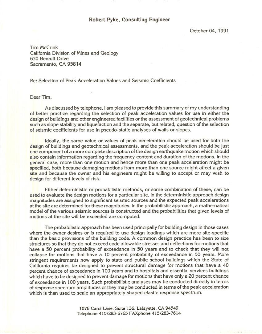
5 Page 5 of 10 and reorientation of particles is still going on at up to 49 days after the field trial, suggesting that measurements should have been made at additional intervals after the test. Another is that while the measured shear wave velocities in the sand fill increased as a result of densification, they did not increase in proportion nearly as much as the cone tip resistances. This is readily explainable because the penetration resistance is a more direct function of the packing of the particles whereas the shear wave velocity is to some extent a function of that but also very much a function of the condition of the particle contacts. Densification by vibration disrupts the particle contacts and in some materials causes a decrease in the shear wave velocity even though the density has been increased. This phenomenon has been recognized for some years and is addressed in the Terzaghi Lectures of both Mitchell (1986) and Schmertmann (1991). An estimate of the long term shear wave velocity can still be made in the case of the sand fill because the SPT blow counts implied by the cone tip resistances are in the order of 30, which translates using standard relationships to shear wave velocities in the order of 1000 to 1200 ft/sec, which is what one would expect for a very dense sand. The third interesting thing is that while anecdotal reports and the cone tip resistances suggest that even heavy vibration had no impact on the density of the clayey sands that comprise the shoal materials, the measured shear wave velocities decreased. Again this is readily explainable. Even if the packing of the shoal materials, as seen in electron micrographs, and the distribution of clay particles is such that heavy vibration (or earthquake shaking) does not densify these materials, the particle contacts will still be disrupted. These shear wave velocities will surely recover with enough time, but whether long term they will equal or even exceed the original values is not known and can only be established by measurements that are made over a period of several years or more. So, not only does the basic data required to perform more sophisticated deformation analyses not exist, but it might take several years to acquire such data. This also applies to any properties that need to be determined from laboratory tests. In addition to any errors caused by sample disturbance or seating issues, laboratory tests performed on samples taken shortly after the trial densification will be in error because the particle contacts have not settled down and aged. This raises the question of whether in the meantime there is any screening analysis that is appropriate for this site. The short answer is yes, there is. As explained by Harry Seed in his Rankine lecture (Seed, 1979), for materials that do not undergo a loss of strength and stiffness as a result of cyclic loading, pseudo-static analyses are not too bad. That in turn raises the question of what seismic coefficient should be used in a pseudo-static analysis but a robust answer to that is provided in Pyke (1991), which drew on the work of Makdisi and Seed (1978). Or, alternately one can use Makdisi and Seed (1978), which has less shortcomings than any other simplified method for computing deformations. Strictly speaking Makdisi and Seed only applies to dams ranging in height from 50 to 250 feet, but the Treasure Island revetment falls near the lower end of this range.
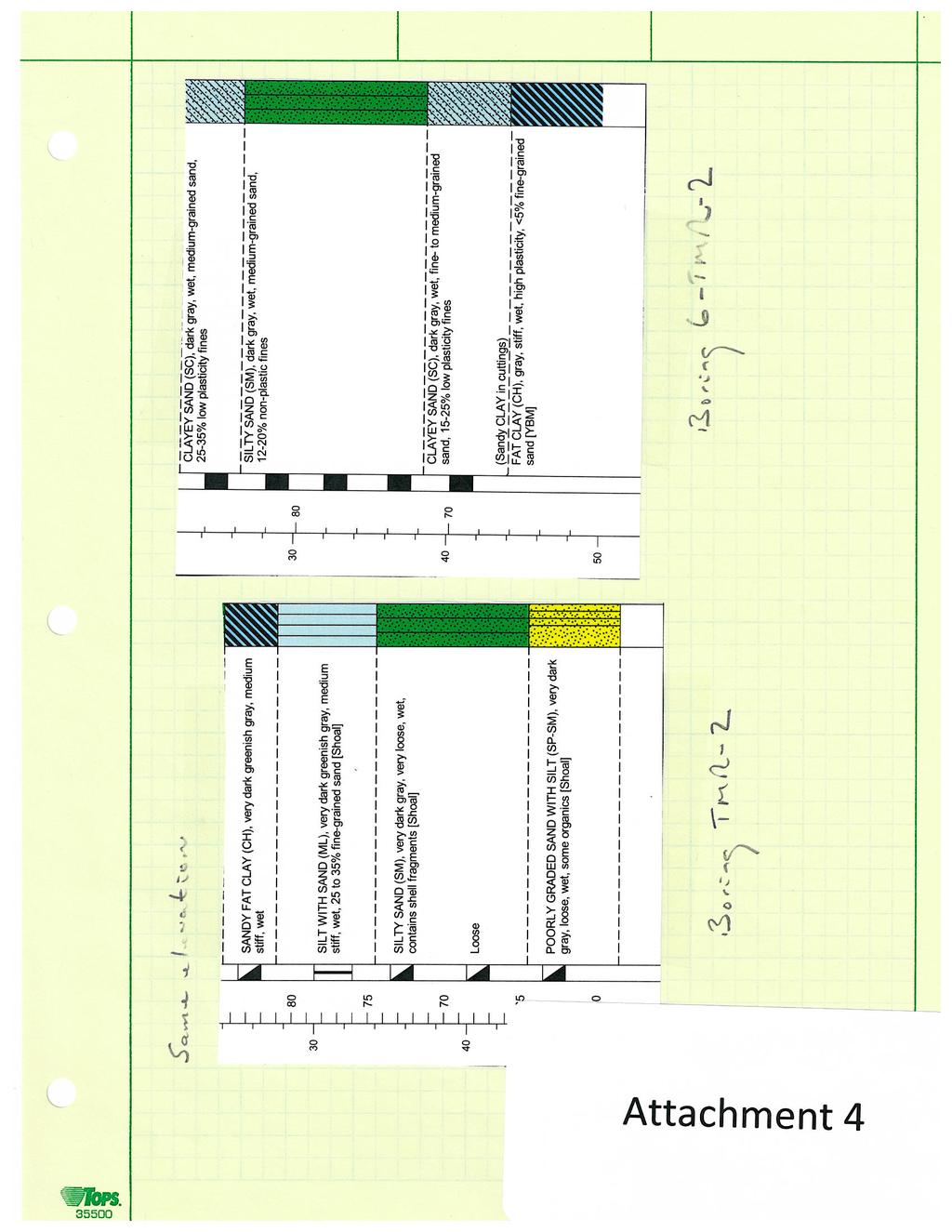
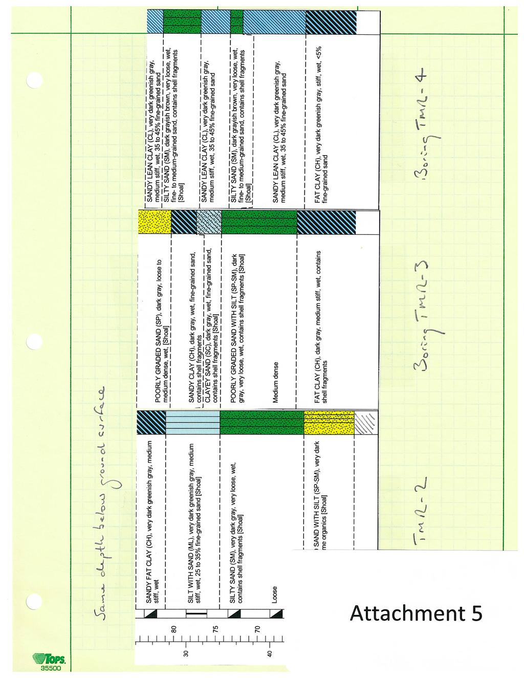
6 Page 6 of 10 Both pseudo-static and Makdisi and Seed analyses require knowledge of the expected peak acceleration and the earthquake magnitude. Conservatively assuming up to a magnitude 7.3 earthquake on the combined Hayward Rogers Creek fault and an up to magnitude 8.1 earthquake on the San Andreas fault, the project geotechnical consultant computed a peak acceleration for the site of 0.46 g using the computer program SHAKE to perform an equivalent linear site response analyses. In order to compute both the static factor of safety and the yield acceleration (the seismic coefficient that reduces the factor of safety to unity the factor of safety for a specified seismic coefficient can be derived from this) for Section D-D I have used the computer program TSLOPE. TSLOPE is a new slope stability program which allows 3D analyses as well as 2D analyses. It is available for a free trial at For Section D-D, when a circular slip circle is transformed to a spherical or ellipsoidal slip surface, two things happen. One is that the slip surface now has to cut through the rock revetment, rather than diving under it this will increase the factor of safety. The other is that relatively more of the slip surface will be in the young Bay Mud this might either reduce or increase the factor of safety. I have used both the methods of solution that are available in TSLOPE the Ordinary Method of Columns (OMC), which I prefer, and Spencer s Method, which is more generally accepted, or rather I should say wrongly pushed by academics. The geometry and the properties that I have used are recorded in the input files, which I will be happy to make available to interested parties. Because hard data are not available for many of the required properties, I have used my judgement, based on 40 plus years of local practice, where necessary. For the young Bay Mud layer I have adopted the project geotechnical consultant s value of 0.3 for the ratio of the undrained shear strength divided by the effective vertical stress and I have divided the young Bay Mud layer into four zones for purposes of computing its undrained shear strength. For the zone that is going to be overconsolidated by wicking and surcharging I have increased the undrained shear strength by 50 percent, corresponding to an OCR value of a little more than 1.5. For the other zones I have assumed that the Bay Mud is normally consolidated under the current overburden. I have conservatively assumed that the lower strength sand layer extends to under the heel of the lower triangle of rockfill, even though I believe that some or all of this material can be densified. For the static loading case I have used undrained strengths in the young Bay Mud and drained strengths in the other materials. For the seismic loading case I have used undrained strengths for all materials below the water table, except for the rockfill in the revetment. I have also corrected these strengths for rate of loading effects in order to represent the short rise time of an earthquake pulse. These corrections are based on UC Berkeley Ph.D. theses by Gerry Thiers and Willie Lacerda as well as other data reported by Pyke (1981) and Bea (1999). For the shoal materials I assumed a base undrained shear strength of 2000 psf based on the test data shown in Attachment 3. Note that UU tests normally give undrained shear strengths on
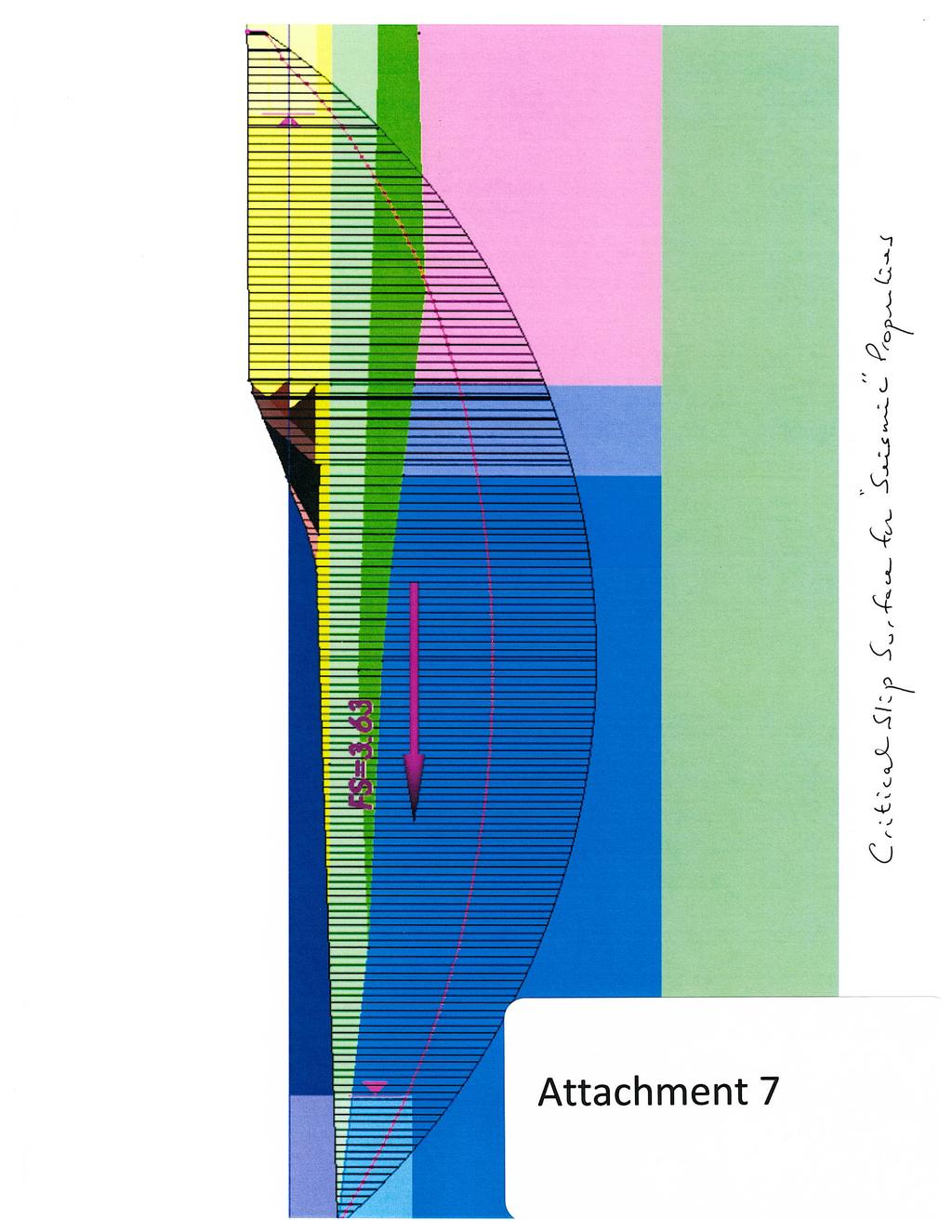
7 Page 7 of 10 the low side. The project geotechnical consultant has subdivided the shoal materials into two layers but I do not see convincing evidence for that and have modelled it as a single layer. The logs of a pair of adjacent borings and three more widely spaced borings are shown in Attachments 4 and 5. The critical circular slip surfaces obtained using Spencer s method and the static and seismic properties are shown in Attachments 6 and 7. These are both for static analyses without the application of a seismic coefficient. The critical circular slip surface obtained in the static analysis with seismic properties was then used in subsequent searches for the yield acceleration. The critical 2D failure surface was also used as the basis for constructing three 3D failure surfaces, as shown in Attachment 8. The center 3D slip surface is a sphere, which has an aspect ratio of 1.0. In addition there are two further ellipsoids that have aspect ratios of 0.5 and 2.0. The larger the aspect ratio, the more the 3D solution approaches the 2 D solution. Again, the reason that the 3D factors of safety are higher than the 2D is that in 3D you have to cut through the revetment, rather than diving under it as you do in 2D. Of the four cases, the one with the aspect ratio of 0.5, which gives the highest factor of safety, is probably the most like an actual landslide. OMC Spencer Static analyses D FoS D FoS aspect ratio = D FoS aspect ratio = D FoS aspect ratio = 0.5 Seismic analyses 0.22g 0.26g 2D yield acceleration 0.27g 0.31g 3D yield acceleration aspect ratio = g 0.33g 3D yield acceleration aspect ratio = g 0.39g 3D yield acceleration aspect ratio = 0.5 The results are shown in the above table. As expected for a slope that has been stable for many years and would have been at greatest risk at the end of construction, the static factors of safety are healthy enough to suggest that there is some margin of safety to accommodate earthquake loadings.
8 Page 8 of 10 Recall that the design peak acceleration for the site is 0.46g. At most, the seismic coefficient that should be used in a pseudo-static analysis is half that, or 0.23g (see Pyke, 1991). That would be for a magnitude 8 earthquake on the San Andreas fault. Except for the 2D analysis using the OMC, all the yield accelerations (the seismic coefficient that reduces the factor of safety to unity) are greater than 0.25, implying factors of safety in pseudo-static analyses of more than 1.1, which is the accepted standard in California for passing a screening analysis. And, if you meet the screening analysis criteria, you are not required to attempt more detailed or sophisticated analyses. Taking the yield acceleration for the aspect ratio of 0.5 and the OMC, which in my judgment is the best answer, the implied factor of safety using the highest possible seismic coefficient in a pseudo-static analysis is actually 1.5! There is no rational argument for requiring any further analyses even if an extensive field and laboratory investigation were to be undertaken to acquire the kind of data that would be needed. I have taken the results below one step further and illustrated the expected seismic displacements in Attachment 9, using Figure 1 from the McCrink letter (Pyke, 1991, which is attached). The computed ratios of the yield acceleration divided by the peak acceleration range from about 0.5 to about 0.75, with the higher values being likely more correct. Thus the expected displacements from both San Andreas and Hayward fault events are small, less than 1 foot, and in the worst case the San Andreas displacements might be something like 2 feet. These seem like entirely reasonable results for the site after densification of the sand fill and wicking and surcharging of the ybm. There is no precedent for failure of a fill over young Bay Mud many years after the initial construction when the young Bay Mud has fully consolidated, let alone when it has been overconsolidated by wicking and surcharging, even in the Loma Prieta earthquake which generated strong ground motions around at least parts of the Bay. Conclusions Simplified analyses using conventional procedures and 2D slope stability analyses are unnecessarily conservative, and in this case suggest that there is a problem where no problem actually exists. Furthermore, any effort that is made to improve shoreline stability by introducing relatively stiff soil-cement walls or cells is likely to worsen the situation rather than improving it. Such measures would surely result in longitudinal cracking as a result of strain incompatibility and would likely increase the tendency for the revetment to shed into the Bay. And, requiring the construction of soil-cement walls or cells when they are not in fact needed, will often have adverse effects on schedule and introduce unnecessary headaches with regard to construction quality control.
9 Page 9 of 10 Next generation software tools such as TSLOPE (and our forthcoming pile and wall analysis program TPILE) are intended to provide geotechnical engineers not with more sophisticated tools just for the sake of it, but with tools that better match both reality and common-sense and lead to designs which are both more economical and safer. References Baligh, M.M., and Azzouz, A.S., End Effects on Cohesive Slopes, Journal of Geotechnical Engineering, ASCE, Volume 101, No. 11, 1975 Bea, R.G., et al. Evaluation of Reliability of Platform Pile Foundations, Journal of Geotechnical and Geoenvironmental Engineering, ASCE, Vol. 125 No.8, August 1999 Boulanger, R.W., Lateral Spreading in Interbedded Sand, Silt and Clay Deposits, Cark Canal, Idriss Symposium, UC Davis, June 17, 2016 Makdisi, F.I., and Seed, H.B., 'Simplified Procedure for Estimating Dam and Embankment Earthquake- Induced Deformations', Journal of Geotechnical Engineering, ASCE, Vol.104, No.GT?, July Mitchell, J.K., Practical Problems from Surprising Soil Behavior - the Twentieth Terzaghi Lecture, Journal of Geotechnical Engineering, ASCE, Vol. 112, No. 3, pp , 1986 Pyke, R., A Preliminary Study of Rate of Loading Effects on Axial Pile Capacities, Report prepared for Union Oil Company Science and Technology Division, December 1981 Pyke, R., Selection of Peak Acceleration Values and Seismic Coefficients, letter to Tim McCrink of the California Division of Mines and Geology, October Pyke, R., et al., Modeling of Dynamic Soil Properties, Appendix 7.A, Guidelines for Determining Design Basis Ground Motions, Report No. TR , Electric Power Research Institute, November 1993 Pyke, R., Evaluating the Potential for Earthquake-Induced Liquefaction in Practice, 6 th International Conference on Earthquake Geotechnical Engineering, Christchurch, New Zealand, November, Schmertmann, J.H., "The Mechanical Ageing of Soils the Twenty Fifth Terzaghi Lecture", Journal of Geotechnical Engineering, ASCE, Vol. 117, No. 9, 1991
10 Page 10 of 10 Seed, H.B., 'Nineteenth Rankine Lecture: Considerations in the Earthquake Resistant Design of Earth and Rockfill Dams', Geotechnique, Vol.24, No.3, September Vahdani, S., Egan, J., Pyke, R., Seismic Design Ground Motion and Site Response Analysis Procedure Prepared for Port of Oakland, Report prepared by Geotechnical Seismic Design Review Board, 2002
11
12
13
14
15
16
17
18
19
20
21
22
23
24
25
Mitigation of Liquefaction Potential Using Rammed Aggregate Piers
 ASCE 2011 557 Mitigation of Liquefaction Potential Using Rammed Aggregate Piers R.W. Rudolph, M. ASCE, G.E. 1, B. Serna, M. ASCE, P.E. 2, and T. Farrell, M. ASCE, G.E. 3 1 Principal Consultant, ENGEO,
Liquefaction and Foundations
 Liquefaction and Foundations Amit Prashant Indian Institute of Technology Gandhinagar Short Course on Seismic Design of Reinforced Concrete Buildings 26 30 November, 2012 What is Liquefaction? Liquefaction
Evaluating the Seismic Coefficient for Slope Stability Analyses
 Evaluating the Seismic Coefficient for Slope Stability Analyses by Edward Kavazanjian, Jr., Ph.D., P.E.,D.GE., NAE Ira A. Fulton Professor of Geotechnical Engineering School of Sustainable Engineering
IN SITU TESTING TECHNOLOGY FOR FOUNDATION & EARTHQUAKE ENGINEERING. Wesley Spang, Ph.D., P.E. AGRA Earth & Environmental, Inc.
 IN SITU TESTING TECHNOLOGY FOR FOUNDATION & EARTHQUAKE ENGINEERING Wesley Spang, Ph.D., P.E. AGRA Earth & Environmental, Inc. Portland, Oregon In situ testing of soil, which essentially consists of evaluating
Seismic Evaluation of Tailing Storage Facility
 Australian Earthquake Engineering Society 2010 Conference, Perth, Western Australia Seismic Evaluation of Tailing Storage Facility Jonathan Z. Liang 1, David Elias 2 1 Senior Geotechnical Engineer, GHD
(THIS IS ONLY A SAMPLE REPORT OR APPENDIX OFFERED TO THE USERS OF THE COMPUTER PROGRAM
 C A U T I O N!! (THIS IS ONLY A SAMPLE REPORT OR APPENDIX OFFERED TO THE USERS OF THE COMPUTER PROGRAM EQLique&Settle2. THE AUTHOR IS HEREBY RELEASED OF ANY LIABILITY FOR ANY INCORRECT USE OF THIS SAMPLE
EARTHQUAKE-INDUCED SETTLEMENTS IN SATURATED SANDY SOILS
 VOL., NO., AUGUST 7 ISSN 119- -7 Asian Research Publishing Network (ARPN). All rights reserved. EARTHQUAKE-INDUCED SETTLEMENTS IN SATURATED SANDY SOILS C. Y. Lee Department of Civil Engineering, College
Evaluation of soil liquefaction using the CPT Part 1
 Evaluation of soil liquefaction using the CPT Part 1 Dr. Peter K. Robertson Webinar #7 2013 CPT Guide 5 th Edition Download FREE copy from: Robertson & Cabal (Robertson) 5 th Edition 2012 www.greggdrilling.com
Date: April 2, 2014 Project No.: Prepared For: Mr. Adam Kates CLASSIC COMMUNITIES 1068 E. Meadow Circle Palo Alto, California 94303
 City of Newark - 36120 Ruschin Drive Project Draft Initial Study/Mitigated Negative Declaration Appendix C: Geologic Information FirstCarbon Solutions H:\Client (PN-JN)\4554\45540001\ISMND\45540001 36120
Evaluation of Geotechnical Hazards
 Evaluation of Geotechnical Hazards by Geoffrey R. Martin Appendix B: Evaluation of Geotechnical Hazards Describes Evaluation Procedures Soil Liquefaction Soil Settlement Surface Fault Rupture Flooding
SOME OBSERVATIONS RELATED TO LIQUEFACTION SUSCEPTIBILITY OF SILTY SOILS
 SOME OBSERVATIONS RELATED TO LIQUEFACTION SUSCEPTIBILITY OF SILTY SOILS Upul ATUKORALA 1, Dharma WIJEWICKREME 2 And Norman MCCAMMON 3 SUMMARY The liquefaction susceptibility of silty soils has not received
Liquefaction assessments of tailings facilities in low-seismic areas
 Page 1 Liquefaction assessments of tailings facilities in low-seismic areas Holly Rourke SRK Consulting, Perth, WA, Australia Caroline Holmes SRK Consulting, Perth, WA, Australia This paper was first presented
CPT Applications - Liquefaction 2
 CPT Applications - Liquefaction 2 Peter K. Robertson CPT in Geotechnical Practice Santiago, Chile July, 2014 Definitions of Liquefaction Cyclic (seismic) Liquefaction Zero effective stress (during cyclic
On seismic landslide hazard assessment: Reply. Citation Geotechnique, 2008, v. 58 n. 10, p
 Title On seismic landslide hazard assessment: Reply Author(s) Yang, J; Sparks, A.D.W. Citation Geotechnique, 28, v. 58 n. 1, p. 831-834 Issued Date 28 URL http://hdl.handle.net/1722/58519 Rights Geotechnique.
Seismic Stability of Tailings Dams, an Overview
 Seismic Stability of Tailings Dams, an Overview BY Gonzalo Castro, Ph.D., P.E. Principal International Workshop on Seismic Stability of Tailings Dams Case Western Reserve University, November 2003 Small
SLOPE STABILITY EVALUATION AND ACCEPTANCE STANDARDS
 INFORMATION BULLETIN / PUBLIC - BUILDING CODE REFERENCE NO.: LAMC 98.0508 Effective: 1-26-84 DOCUMENT NO. P/BC 2002-049 Revised: 11-1-02 Previously Issued As: RGA #1-84 SLOPE STABILITY EVALUATION AND ACCEPTANCE
Prof. B V S Viswanadham, Department of Civil Engineering, IIT Bombay
 19 Module 5: Lecture -1 on Stability of Slopes Contents Stability analysis of a slope and finding critical slip surface; Sudden Draw down condition, effective stress and total stress analysis; Seismic
Back Analysis of the Lower San Fernando Dam Slide Using a Multi-block Model
 Proceedings Geohazards Engineering Conferences International Year 2006 Back Analysis of the Lower San Fernando Dam Slide Using a Multi-block Model C. A. Stamatopoulos P. Petridis Stamatopoulos and Associates
Case History of Observed Liquefaction-Induced Settlement Versus Predicted Settlement
 Case History of Observed Liquefaction-Induced Settlement Versus Predicted Settlement M. Lew and L. Tran AMEC Environment & Infrastructure, Inc., Los Angeles, CA USA SUMMARY: A comparison of the predicted
PRINCIPLES OF GEOTECHNICAL ENGINEERING
 PRINCIPLES OF GEOTECHNICAL ENGINEERING Fourth Edition BRAJA M. DAS California State University, Sacramento I(T)P Boston Albany Bonn Cincinnati London Madrid Melbourne Mexico City New York Paris San Francisco
Liquefaction: Additional issues. This presentation consists of two parts: Section 1
 Liquefaction: Additional issues Ahmed Elgamal This presentation consists of two parts: Section 1 Liquefaction of fine grained soils and cyclic softening in silts and clays Section 2 Empirical relationship
Liquefaction Potential Variations Influenced by Building Constructions
 Earth Science Research; Vol. 1, No. 2; 2012 ISSN 1927-0542 E-ISSN 1927-0550 Published by Canadian Center of Science and Education Liquefaction Potential Variations Influenced by Building Constructions
Important Concepts. Earthquake hazards can be categorized as:
 Lecture 1 Page 1 Important Concepts Monday, August 17, 2009 1:05 PM Earthquake Engineering is a branch of Civil Engineering that requires expertise in geology, seismology, civil engineering and risk assessment.
Evaluation of soil liquefaction using the CPT Part 2
 Evaluation of soil liquefaction using the CPT Part 2 P.K. Robertson 2013 Definitions of Liquefaction Cyclic (seismic) Liquefaction Zero effective stress (during cyclic loading) Flow (static) Liquefaction
Module 3. DYNAMIC SOIL PROPERTIES (Lectures 10 to 16)
") Module 3 DYNAMIC SOIL PROPERTIES (Lectures 10 to 16) Lecture 15 Topics 3.6 STRESS-STRAIN BEHAVIOR OF CYCLICALLY LOADED SOILS 3.7 SOME BASIC ASPECTS OF PARTICULATE MATTER BEHAVIOR 3.8 EQUIVALENT LINEAR
Module 3 DYNAMIC SOIL PROPERTIES (Lectures 10 to 16) Lecture 15 Topics 3.6 STRESS-STRAIN BEHAVIOR OF CYCLICALLY LOADED SOILS 3.7 SOME BASIC ASPECTS OF PARTICULATE MATTER BEHAVIOR 3.8 EQUIVALENT LINEAR
STUDY OF THE BEHAVIOR OF PILE GROUPS IN LIQUEFIED SOILS
 STUDY OF THE BEHAVIOR OF PILE GROUPS IN LIQUEFIED SOILS Shin-Tower Wang 1, Luis Vasquez 2, and Lymon C. Reese 3, Honorary Member,, ASCE ABSTRACT : 1&2 President & Project Manager, Ensoft, Inc. Email: ensoft@ensoftinc.com
LIQUEFACTION OF EARTH EMBANKMENT DAMS TWO CASE HISTORIES: (1) LIQUEFACTION OF THE EMBANKMENT SOILS, AND (2) LIQUEFACTION OF THE FOUNDATIONS SOILS
 LIQUEFACTION OF THE EMBANKMENT SOILS, AND (2) LIQUEFACTION OF THE FOUNDATIONS SOILS") LIQUEFACTION OF EARTH EMBANKMENT DAMS TWO CASE HISTORIES: (1) LIQUEFACTION OF THE EMBANKMENT SOILS, AND (2) LIQUEFACTION OF THE FOUNDATIONS SOILS Antonio Fernandez, Ph.D. 1 ABSTRACT Paul C. Rizzo Associates,
LIQUEFACTION OF EARTH EMBANKMENT DAMS TWO CASE HISTORIES: (1) LIQUEFACTION OF THE EMBANKMENT SOILS, AND (2) LIQUEFACTION OF THE FOUNDATIONS SOILS Antonio Fernandez, Ph.D. 1 ABSTRACT Paul C. Rizzo Associates,
Seismic Slope Stability
 ISSN (e): 2250 3005 Volume, 06 Issue, 04 April 2016 International Journal of Computational Engineering Research (IJCER) Seismic Slope Stability Mohammad Anis 1, S. M. Ali Jawaid 2 1 Civil Engineering,
Numerical analysis of effect of mitigation measures on seismic performance of a liquefiable tailings dam foundation
 Numerical analysis of effect of mitigation measures on seismic performance of a liquefiable tailings dam foundation Yong-Beom Lee, Jorge Castillo Ausenco, USA Aurelian C. Trandafir Fugro GeoConsulting
Soil Dynamics Prof. Deepankar Choudhury Department of Civil Engineering Indian Institute of Technology, Bombay
 Soil Dynamics Prof. Deepankar Choudhury Department of Civil Engineering Indian Institute of Technology, Bombay Module - 4 Lecture 21 Dynamic Soil, Properties Estimation of Gmax, Modulus Reduction Curves,
Guidelines for Site-Specific Seismic Hazard Reports for Essential and Hazardous Facilities and Major and Special-Occupancy Structures in Oregon
 Guidelines for Site-Specific Seismic Hazard Reports for Essential and Hazardous Facilities and Major and Special-Occupancy Structures in Oregon By the Oregon Board of Geologist Examiners and the Oregon
Case Study - Undisturbed Sampling, Cyclic Testing and Numerical Modelling of a Low Plasticity Silt
 6 th International Conference on Earthquake Geotechnical Engineering 1-4 November 2015 Christchurch, New Zealand Case Study - Undisturbed Sampling, Cyclic Testing and Numerical Modelling of a Low Plasticity
Liquefaction induced ground damage in the Canterbury earthquakes: predictions vs. reality
 Bowen, H. J. & Jacka, M. E. () Proc. th NZGS Geotechnical Symposium. Ed. CY Chin, Queenstown Liquefaction induced ground damage in the Canterbury earthquakes: predictions vs. reality H J Bowen & M E Jacka
Liquefaction. Ajanta Sachan. Assistant Professor Civil Engineering IIT Gandhinagar. Why does the Liquefaction occur?
 Liquefaction Ajanta Sachan Assistant Professor Civil Engineering IIT Gandhinagar Liquefaction What is Liquefaction? Why does the Liquefaction occur? When has Liquefaction occurred in the past? Where does
Effective stress analysis of pile foundations in liquefiable soil
 Effective stress analysis of pile foundations in liquefiable soil H. J. Bowen, M. Cubrinovski University of Canterbury, Christchurch, New Zealand. M. E. Jacka Tonkin and Taylor Ltd., Christchurch, New
Module 6 LIQUEFACTION (Lectures 27 to 32)
") Module 6 LIQUEFACTION (Lectures 27 to 32) Lecture 31 Topics 6.6 EFFECTS OF LIQUEFACTION 6.6.1 Alteration of Ground Motion 6.6.2 Development of Sand Boils 6.6.3 Settlement 6.6.4 Settlement of Dry Sands
Module 6 LIQUEFACTION (Lectures 27 to 32) Lecture 31 Topics 6.6 EFFECTS OF LIQUEFACTION 6.6.1 Alteration of Ground Motion 6.6.2 Development of Sand Boils 6.6.3 Settlement 6.6.4 Settlement of Dry Sands
2D Liquefaction Analysis for Bridge Abutment
 D Liquefaction Analysis for Bridge Abutment Tutorial by Angel Francisco Martinez Integrated Solver Optimized for the next generation 64-bit platform Finite Element Solutions for Geotechnical Engineering
SLOPE STABILITY EVALUATION AND ACCEPTANCE STANDARDS
 INFORMATION BULLETIN / PUBLIC - BUILDING CODE REFERENCE NO.: LABC 7006.3, 7014.1 Effective: 01-01-2017 DOCUMENT NO.: P/BC 2017-049 Revised: 12-21-2016 Previously Issued As: P/BC 2014-049 SLOPE STABILITY
LIQUEFACTION ASSESSMENT OF INDUS SANDS USING SHEAR WAVE VELOCITY
 Pakistan Engineering Congress, 69th Annual Session Proceedings 219 LIQUEFACTION ASSESSMENT OF INDUS SANDS USING SHEAR WAVE VELOCITY Sohail Kibria 1, M. Javed 2, Muhammad Ali 3 ABSTRACT A host of procedures
Slope Stability Evaluation Ground Anchor Construction Area White Point Landslide San Pedro District Los Angeles, California.
 Slope Stability Evaluation Ground Anchor Construction Area White Point Landslide San Pedro District Los Angeles, California Submitted To: Mr. Gene Edwards City of Los Angeles Department of Public Works
Numerical model comparison on deformation behavior of a TSF embankment subjected to earthquake loading
 Numerical model comparison on deformation behavior of a TSF embankment subjected to earthquake loading Jorge Castillo, Yong-Beom Lee Ausenco, USA Aurelian C. Trandafir Fugro GeoConsulting Inc., USA ABSTRACT
Engineer. Engineering. Engineering. (in-ja-neer ) A person trained and skilled in any of the various branches of engineering: a civil engineer
 A person trained and skilled in any of the various branches of engineering: a civil engineer") Engineer (in-ja-neer ) A person trained and skilled in any of the various branches of engineering: a civil engineer (Random House Webster s College Dictionary, 1991) CE100 Introduction to Civil Geotechnical
Engineer (in-ja-neer ) A person trained and skilled in any of the various branches of engineering: a civil engineer (Random House Webster s College Dictionary, 1991) CE100 Introduction to Civil Geotechnical
Review of static and seismic stability of a cross-valley sand tailings embankment in a high rainfall, high seismicity setting
 Tailings and Mine Waste Management for the 21 st Century 2015 Paper Number: 52 Review of static and seismic stability of a cross-valley sand tailings embankment in a high rainfall, high seismicity setting
DEVELOPMENT OF A METHODOLOGY FOR ESTIMATING SIMPLIFIED SEISMIC SLOPE DEFORMATION OF LEVEES WITH SEEPAGE CONTROL MEASURES
 Paper No. DOALI DEVELOPMENT OF A METHODOLOGY FOR ESTIMATING SIMPLIFIED SEISMIC SLOPE DEFORMATION OF LEVEES WITH SEEPAGE CONTROL MEASURES John Liao 1, Ph.D., P.E., Zia Zafir, Ph.D., P.E., G.E., Scott Anderson,
Liquefaction-Induced Lateral Spreading Misko Cubrinovski University of Canterbury, Christchurch, New Zealand
 US New Zealand Japan International Workshop Liquefaction-Induced Ground Movements Effects UC Berkeley, California, 2 4 November 2016 Liquefaction-Induced Lateral Spreading Misko Cubrinovski University
QUAKE/W ProShake Comparison
 1 Introduction QUAKE/W Comparison is a commercially available software product for doing one-dimensional ground response analyses. It was developed and is being maintained under the guidance of Professor
POST CYCLIC SHEAR STRENGTH OF FINE GRAINED SOILS IN ADAPAZARI TURKEY DURING 1999 KOCAELI EARTHQUAKE
 POST CYCLIC SHEAR STRENGTH OF FINE GRAINED SOILS IN ADAPAZARI TURKEY DURING 1999 KOCAELI EARTHQUAKE A.Erken 1, Z.Kaya 2 and A.Şener 3 1 Professor Istanbul Technical University, Civil Engineering Faculty,
Dynamic Analysis Contents - 1
 Dynamic Analysis Contents - 1 TABLE OF CONTENTS 1 DYNAMIC ANALYSIS 1.1 Overview... 1-1 1.2 Relation to Equivalent-Linear Methods... 1-2 1.2.1 Characteristics of the Equivalent-Linear Method... 1-2 1.2.2
Deep Foundations 2. Load Capacity of a Single Pile
 Deep Foundations 2 Load Capacity of a Single Pile All calculations of pile capacity are approximate because it is almost impossible to account for the variability of soil types and the differences in the
IAEA SAFETY STANDARDS Geotechnical Aspects of Site Evaluation and Foundations in NPPs, NS-G-3.6
 IAEA SAFETY STANDARDS Geotechnical Aspects of Site Evaluation and Foundations in NPPs, NS-G-3.6 Regional Workshop on Volcanic, Seismic, and Tsunami Hazard Assessment Related to NPP Siting Activities and
FRIENDS OF THE EEL RIVER
 FRIENDS OF THE EEL RIVER Working for the recovery of our Wild & Scenic River, its fisheries and communities. Frank Blackett, Regional Engineer Office of Energy Projects Division of Dam Safety and Inspections
ANALYSIS OF A SLOPE FAILURE IN AN OPEN PIT MINE USING TSLOPE
 ANALYSIS OF A SLOPE FAILURE IN AN OPEN PIT MINE USING TSLOPE 1. Background In 1996 a slope failure occurred at the Round Hill open pit mine, operated by Macraes Mining Company Ltd. The failure as shown
An Overview of Geotechnical Earthquake Engineering
 An Overview of Geotechnical Earthquake Engineering Sudhir K Jain Slide 1 Outline Introduction to Seismic Design Principle Dynamic Soil Properties Site Effects Soil Structure Interaction Issues for Foundation
Chapter 7 GEOMECHANICS
 Chapter 7 Final SCDOT GEOTECHNICAL DESIGN MANUAL August 2008 Table of Contents Section Page 7.1 Introduction...7-1 7.2 Geotechnical Design Approach...7-1 7.3 Geotechnical Engineering Quality Assurance...7-2
EFFECTIVE STRESS ANALYSES OF TWO SITES WITH DIFFERENT EXTENT OF LIQUEFACTION DURING EAST JAPAN EARTHQUAKE
 Proceedings of the International Symposium on Engineering Lessons Learned from the 211 Great East Japan Earthquake, March 1-4, 212, Tokyo, Japan EFFECTIVE STRESS ANALYSES OF TWO SITES WITH DIFFERENT EXTENT
Residual Deformation Analyses to Demonstrate the Effect of Thin Steel Sheet Piles on Liquefaction-Induced Penetration Settlement of Wooden Houses
 6 th International Conference on Earthquake Geotechnical Engineering 1-4 November 2015 Christchurch, New Zealand Residual Deformation Analyses to Demonstrate the Effect of Thin Steel Sheet Piles on Liquefaction-Induced
GEOLOGY AND SOILS. This chapter summarizes geologic and geotechnical aspects of the site as they relate to the Project.
 9 GEOLOGY AND SOILS INTRODUCTION This chapter summarizes geologic and geotechnical aspects of the site as they relate to the Project. This chapter utilizes information from the following reports prepared
DRAFT ONONDAGA LAKE CAPPING AND DREDGE AREA AND DEPTH INITIAL DESIGN SUBMITTAL H.4 SEISMIC SLOPE STABILITY ANALYSES
 DRAFT ONONDAGA LAKE CAPPING AND DREDGE AREA AND DEPTH INITIAL DESIGN SUBMITTAL H.4 SEISMIC SLOPE STABILITY ANALYSES Parsons P:\Honeywell -SYR\444576 2008 Capping\09 Reports\9.3 December 2009_Capping and
Micro Seismic Hazard Analysis
 Micro Seismic Hazard Analysis Mark van der Meijde INTERNATIONAL INSTITUTE FOR GEO-INFORMATION SCIENCE AND EARTH OBSERVATION Overview Site effects Soft ground effect Topographic effect Liquefaction Methods
The Travails of the Average Geotechnical Engineer Using the National Seismic Hazard Maps
 The Travails of the Average Geotechnical Engineer Using the National Seismic Hazard Maps Marshall Lew Amec Foster Wheeler Environment & Infrastructure Los Angeles, California Amec Foster Wheeler 2015.
NEW METHOD FOR LIQUEFACTION ASSESSMENT BASED ON SOIL GRADATION AND RELATIVE DENSITY
 NEW METHOD FOR LIQUEFACTION ASSESSMENT BASED ON SOIL GRADATION AND RELATIVE DENSITY Bambang Istijono 1, Abdul Hakam 2 1,2 Civil Dept. of Engineering Faculty, University of Andalas, Padang, Indonesia ABSTRACT
GEOLOGY, SOILS, AND SEISMICITY
 4.9 GEOLOGY, SOILS, AND SEISMICITY 4.9.1 Introduction Information about the geological conditions and seismic hazards in the study area was summarized in the FEIR, and was based on the Geotechnical Exploration
Roy Pyle March 24, 2017 Chief Facilities Planner Contra Costa Community College District 500 North Court Street Martinez, CA 94533
 State of California Natural Resources Agency Edmund G. Brown Jr., Governor Department of Conservation John G. Parrish, Ph.D., State Geologist California Geological Survey 801 K Street MS 12-31 Sacramento,
Amplification of Seismic Motion at Deep Soil Sites
 20th International Conference on Structural Mechanics in Reactor Technology (SMiRT 20) Espoo, Finland, August 9-14, 2009 SMiRT 20-Division 5, Paper 1740 Amplification of Seismic Motion at Deep Soil Sites
(Refer Slide Time: 02:18)
") Geology and Soil Mechanics Prof. P. Ghosh Department of Civil Engineering Indian Institute of Technology Kanpur Lecture 40 Shear Strength of Soil - C Keywords: Shear strength of soil, direct shear test,
Geology and Soil Mechanics Prof. P. Ghosh Department of Civil Engineering Indian Institute of Technology Kanpur Lecture 40 Shear Strength of Soil - C Keywords: Shear strength of soil, direct shear test,
Table of Contents Chapter 1 Introduction to Geotechnical Engineering 1.1 Geotechnical Engineering 1.2 The Unique Nature of Soil and Rock Materials
 Table of Contents Chapter 1 Introduction to Geotechnical Engineering 1.1 Geotechnical Engineering 1.2 The Unique Nature of Soil and Rock Materials 1.3 Scope of This Book 1.4 Historical Development of Geotechnical
The Seismic Performance of Tousheh Dam During the Chi-Chi Earthquake
 ( C023) Proceedings of 9 th Conference on Current Researches in Geotechnical Engineering, Shihman Reservoir, Tai-Yuan, Taiwan, R.O.C. August 30-3 and September, 200 92 () (the semi-analysis-testing method)(2)
LSN a new methodology for characterising the effects of liquefaction in terms of relative land damage severity
 van Ballegooy, S., Lacrosse, V., Jacka, M. & Malan, P. (2013) Proc. 19 th NZGS Geotechnical Symposium. Ed. CY Chin, Queenstown LSN a new methodology for characterising the effects of liquefaction in terms
Ground Improvement by Dynamic Compaction at a Tailings Disposal Facility
 Missouri University of Science and Technology Scholars' Mine International Conferences on Recent Advances in Geotechnical Earthquake Engineering and Soil Dynamics 2010 - Fifth International Conference
Influences of material dilatancy and pore water pressure on stability factor of shallow tunnels
 Influences of material dilatancy and pore water pressure on stability factor of shallow tunnels YANG Xiao-li( ), HUANG Fu( ) School of Civil and Architectural Engineering, Central South University, Changsha
Evaluation of Liquefaction Potential of Impounded Fly Ash
 2007 World of Coal Ash (WOCA), May 7-10, 2007, Northern Kentucky, USA http://www.flyash.info Evaluation of Liquefaction Potential of Impounded Fly Ash Behrad Zand 1*, Wei Tu 2, Pedro J. Amaya 3, William
IZMIT BAY BRIDGE SOUTH APPROACH VIADUCT: SEISMIC DESIGN NEXT TO THE NORTH ANATOLIAN FAULT
 Istanbul Bridge Conference August 11-13, 2014 Istanbul, Turkey IZMIT BAY BRIDGE SOUTH APPROACH VIADUCT: SEISMIC DESIGN NEXT TO THE NORTH ANATOLIAN FAULT A. Giannakou 1, J. Chacko 2 and W. Chen 3 ABSTRACT
Transactions on the Built Environment vol 3, 1993 WIT Press, ISSN
 Resonant column and cyclic triaxial testing of tailing dam material S.A. Savidis*, C. Vrettos", T. Richter^ "Technical University of Berlin, Geotechnical Engineering Institute, 1000 Berlin 12, Germany
IV. ENVIRONMENTAL IMPACT ANALYSIS G. GEOLOGY AND SOILS
 IV. ENVIRONMENTAL IMPACT ANALYSIS G. GEOLOGY AND SOILS The following section is a summary of the geotechnical report conducted for the proposed project. The Report of Geotechnical Investigation Proposed
Session 2: Triggering of Liquefaction
 Session 2: Triggering of Liquefaction Plenary Speaker: Geoff Martin Professor Emeritus University of Southern California What are the primary deficiencies in the simplified method for evaluation of liquefaction
J. Paul Guyer, P.E., R.A.
 J. Paul Guyer, P.E., R.A. Paul Guyer is a registered mechanical engineer, civil engineer, fire protection engineer and architect with over 35 years experience in the design of buildings and related infrastructure.
Liquefaction potential of Rotorua soils
 Pearse-Danker, E. (2013) Liquefaction potential of Rotorua soils Proc. 19 th NZGS Geotechnical Symposium. Ed. CY Chin, Queenstown Liquefaction potential of Rotorua soils E Pearse-Danker Coffey Geotechnics
Site Response Using Effective Stress Analysis
 Site Response Using Effective Stress Analysis Faiz Makdisi, Zhi-Liang Wang, C.Y. Chang and J. Egan Geomatrix Consultants, Inc. Oakland, California 1 TRB 85 th Annual Meeting, January 22-26, 26, 2006, Washington,
Guidelines on Foundation Loading and Deformation Due to Liquefaction Induced Lateral Spreading
 Guidelines on Foundation Loading and Deformation Due to Liquefaction Induced Lateral Spreading February, 2011 1 INTRODUCTION Past earthquakes offer many examples of bridges that either collapsed or incurred
EARTHQUAKE-INDUCED SETTLEMENT AS A RESULT OF DENSIFICATION, MEASURED IN LABORATORY TESTS
 13 th World Conference on Earthquake Engineering Vancouver, B.C., Canada August 1-6, 2004 Paper No. 3291 EARTHQUAKE-INDUCED SETTLEMENT AS A RESULT OF DENSIFICATION, MEASURED IN LABORATORY TESTS Constantine
Determination of Excess Pore Pressure in Earth Dam after Earthquake
 ABSTRACT: Determination of Excess Pore Pressure in Earth Dam after Earthquake S.M. Nasrollahi Faculty of Islamic Azad University Qaenat Branch, Qaen, Iran. Email: s.m.nasrollahi@gmail.com Pore pressure
1D Analysis - Simplified Methods
 1D Equivalent Linear Method Page 1 1D Analysis - Simplified Methods Monday, February 13, 2017 2:32 PM Reading Assignment Lecture Notes Pp. 255-275 Kramer (EQL method) p. 562 Kramer (Trigonometric Notation
R.SUNDARAVADIVELU Professor IIT Madras,Chennai - 36.
 Behaviour of Berthing Structure under Changing Slope in Seismic Condition - A Case Study K.MUTHUKKUMARAN Research Scholar Department of Ocean Engineering, R.SUNDARAVADIVELU Professor IIT Madras,Chennai
GEOTECHNICAL SEISMIC HAZARDS
 Chapter 13 GEOTECHNICAL SEISMIC HAZARDS FINAL SCDOT GEOTECHNICAL DESIGN MANUAL June 2010 Table of Contents Section Page 13.1 Introduction... 13-1 13.2 Geotechnical Seismic Hazard Failure Modes... 13-2
Introduction to Geotechnical Engineering. ground
 Introduction to Geotechnical Engineering ground 1 Typical Geotechnical Project Geo-Laboratory ~ for testing soil properties Design Office ~ for design & analysis construction site 2 Shallow Foundations
Landslide FE Stability Analysis
 Landslide FE Stability Analysis L. Kellezi Dept. of Geotechnical Engineering, GEO-Danish Geotechnical Institute, Denmark S. Allkja Altea & Geostudio 2000, Albania P. B. Hansen Dept. of Geotechnical Engineering,
Module 8 SEISMIC SLOPE STABILITY (Lectures 37 to 40)
") Module 8 SEISMIC SLOPE STABILITY (Lectures 37 to 40) Lecture 38 Topics 8.5 STATIC SLOPE STABILITY ANALYSIS 8.5.1 Limit Equilibrium Analysis 8.5.2 Stress-Deformation Analyses 8.6 SEISMIC SLOPE STABILITY
Module 8 SEISMIC SLOPE STABILITY (Lectures 37 to 40) Lecture 38 Topics 8.5 STATIC SLOPE STABILITY ANALYSIS 8.5.1 Limit Equilibrium Analysis 8.5.2 Stress-Deformation Analyses 8.6 SEISMIC SLOPE STABILITY
Sensitivity of Liquefaction Triggering Analysis to Earthquake Magnitude
 Australian Earthquake Engineering Society 2013 Conference, Nov 15-17, Hobart, Tasmania Sensitivity of Liquefaction Triggering Analysis to Earthquake Magnitude Dr Timothy I Mote 1 and Minly M. L. So 2 1.
Cyclic Behavior of Sand and Cyclic Triaxial Tests. Hsin-yu Shan Dept. of Civil Engineering National Chiao Tung University
 Cyclic Behavior of Sand and Cyclic Triaxial Tests Hsin-yu Shan Dept. of Civil Engineering National Chiao Tung University Causes of Pore Pressure Buildup due to Cyclic Stress Application Stress are due
Soils. Technical English - I 10 th week
 Technical English - I 10 th week Soils Soil Mechanics is defined as the branch of engineering science which enables an engineer to know theoretically or experimentally the behavior of soil under the action
Presentation Outline. 1. Seismic Soil Liquefaction Explained 2. Presentation of the Software SOILLIQ 3. Illustrative Applications using SOILLIQ
 Presentation Outline 1. Seismic Soil Liquefaction Explained 2. Presentation of the Software SOILLIQ 3. Illustrative Applications using SOILLIQ Foundation Failures in Residential Buildings (1964 Niigata,
Address for Correspondence
 Research Paper DYNAMIC ANALYSIS OF KASWATI EARTH DAM 1 Patel Samir K., 2 Prof. C.S.Sanghavi Address for Correspondence 1 Applied Mechanics Department, 2 Professor, L. D. College of Engineering, Gujarat
Validation Protocols for Constitutive Modeling of Liquefaction
 6 th International Conference on Earthquake Geotechnical Engineering 1-4 November 2015 Christchurch, New Zealand Validation Protocols for Constitutive Modeling of Liquefaction K. Ziotopoulou 1 and R. W.
Assessing effects of Liquefaction. Peter K. Robertson 2016
 Assessing effects of Liquefaction Peter K. Robertson 2016 1964 1995 2010 Flow (static) Liquefaction After Olson & Stark, 2003 Case histories flow liquefaction Common soil features: Very young age Non-plastic
Numerical simulation of inclined piles in liquefiable soils
 Proc. 20 th NZGS Geotechnical Symposium. Eds. GJ Alexander & CY Chin, Napier Y Wang & R P Orense Department of Civil and Environmental Engineering, University of Auckland, NZ. ywan833@aucklanduni.ac.nz
APPENDIX F CORRELATION EQUATIONS. F 1 In-Situ Tests
 APPENDIX F 1 APPENDIX F CORRELATION EQUATIONS F 1 In-Situ Tests 1. SPT (1) Sand (Hatanaka and Uchida, 1996), = effective vertical stress = effective friction angle = atmosphere pressure (Shmertmann, 1975)
The Preliminary Study of the Impact of Liquefaction on Water Pipes
 The Preliminary Study of the Impact of Liquefaction on Water Pipes Jerry J. Chen and Y.C. Chou ABSTRACT Damages to the existing tap-water pipes have been found after earthquake. Some of these damages are
Geotechnical analysis of slopes and landslides: achievements and challenges
 University of Wollongong Research Online Faculty of Engineering - Papers (Archive) Faculty of Engineering and Information Sciences 2010 Geotechnical analysis of slopes and landslides: achievements and
MEDAT-2: Some Geotechnical Opportunities. Site Characterization -- Opportunities. Down-hole CPT & vane (Fugro)
") MEDAT-2: Some Geotechnical Opportunities Ross W. Boulanger Department of Civil & Environmental Engineering University of California Davis, California 95616-5294 rwboulanger@ucdavis.edu Presentation for
MEDAT-2: Some Geotechnical Opportunities Ross W. Boulanger Department of Civil & Environmental Engineering University of California Davis, California 95616-5294 rwboulanger@ucdavis.edu Presentation for
Assessment of Risk of Liquefaction - A Case Study
 Assessment of Risk of Liquefaction - A Case Study ASHWAI JAI Deptt. of Civil Engineering ational Institute Technology Kurukshetra-136119 IDIA ashwani.jain66@yahoo.com Abstract: - Catastrophic failures