EP A1 (19) (11) EP A1 (12) EUROPEAN PATENT APPLICATION. (43) Date of publication: Bulletin 2012/27
|
|
|
- Delilah Kennedy
- 6 years ago
- Views:
Transcription
1 (19) (12) EUROPEAN PATENT APPLICATION (11) EP A1 (43) Date of publication: Bulletin 2012/27 (51) Int Cl.: F16F 6/00 ( ) F16F 15/03 ( ) (21) Application number: (22) Date of filing: (84) Designated Contracting States: AL AT BE BG CH CY CZ DE DK EE ES FI FR GB GR HR HU IE IS IT LI LT LU LV MC MK MT NL NO PL PT RO RS SE SI SK SM TR Designated Extension States: BA ME (71) Applicant: Technische Universiteit Eindhoven 5612 AZ Eindhoven (NL) Paulides, Johannes Jacobus Hubertus 5146 CE Waalwijk (NL) Lomonova, Elena Andreevna 5627 NL Eindhoven (NL) (74) Representative: Beetz, Joeri Deltapatents B.V. Fellenoord ZL Eindhoven (NL) (72) Inventors: Janssen, Jeroen Lodevicus Gerardus 5654 NJ Eindhoven (NL) (54) Vibration isolator (57) A vibration isolator is provided comprising a base structure, a load structure and at least one vertical air gap formed by opposing and substantially parallel walls of the base structure and the load structure. The opposing walls being at least partly covered by respective arrays of permanent magnets, neighboring magnets in the arrays having alternating magnetization directions, an arrangement of the permanent magnets in the arrays being such that a gravitational force on the load structure is substantially compensated by a net magnetic force of the base structure on the load structure. EP A1 Printed by Jouve, PARIS (FR)
2 1 EP A1 2 Description Field of the invention [0001] This invention relates to a vibration isolator comprising a base structure, a load structure and means for compensating a gravitational force on the load structure. Background of the invention [0002] Many industrial engineers, such as in lithographic industry, electron beam microscopy and space applications, deal with accurate positioning systems. Vibrations and other types of mechanical disturbances in such machines easily show up as a major factor in limiting the achievable accuracy, hence require significant reduction. Precise reproduction of the features that continue to get smaller requires good isolation from the environment while productivity concerns driven by market requirements require faster motion. Such demands impose special constraints on a vibration isolation design. Since, in many cases, the structural design of the isolated mass provides little inherent vibration isolation, and passive means provide insufficient isolation over the full required bandwidth, active means are often utilized to provide vibration control. In such applications, high-precision vibration isolation of a large payload with a high mass often requires vacuum compatibility, a contactless structure, high force density and low stiffness. [0003] Air-based solutions are commonly used for actively isolating and controlling vibrations and other types of mechanical disturbances. In most lithographic applications, so-called air mounts are used, which are supplemented by electromechanical Lorentz-actuators providing stability control. A control valve regulates the flow of compressed air into a large air tank acting as a pneumatic spring. Unlike steel coil springs, the resonant frequency of this system is nearly independent of the mass of the payload, and the height control valve regulates the operating height. This provides gravity compensation and spring stiffness, where Lorentz actuators ensure stability and accurate positioning in all degrees of freedom. [0004] The isolation bandwidth of the currently often used pneumatic isolators is generally limited. As a result the vibrations at elevated frequencies are not properly extinguished, which limits the performance of the machine being isolated. Furthermore, air bearings are only suitable for vacuum conditions if significant structural changes are applied which may adversely affect their performance. [0005] Magnet-based vibration isolation systems are increasingly considered to be a feasible alternative for the passive or pneumatic vibration isolation systems. They offer distinct features such as being clean, noiseless and vibration and maintenance free. For these reasons they are increasingly being considered for use in vibration isolation applications. Examples of magnetbased vibration isolators are, e.g., found in US patent application US [0006] In Zero-stiffness magnetic springs for active vibration isolation by Robertson et al., a permanent magnet system is used for obtaining a low stiffness vibration isolation system. This contactless magnetic spring uses attracting magnetic forces from the magnet above the load structure (negative spring, vertically unstable) and repelling magnetic forces from the bottom side (positive spring, vertically stable). These magnetic forces are oriented mainly along the axis of magnetization of the permanent magnets. The resulting vertical magnetic force compensates for the gravity force which is pulling down the load structure. Because the negative spring on the top and the positive spring at the bottom are placed in a parallel configuration, their respective spring stiffness add up and the resulting stiffness is near zero. This gives a vibration isolation system with a low natural resonance frequency to provide enhanced vibration isolation. It is, however, a disadvantage of this magnetic spring type that the low spring stiffness is very local and as a result the spring stiffness varies significantly with the position. This allows for small movements only when low and constant spring stiffness is required or it requires significant control efforts for stabilization and isolation over a larger movement range. Furthermore, such a double-sided topology requires a sandwiched construction which may proof to be disadvantageous if the vertical spring force exerted by such magnetic spring has to be led around the spring by mechanical means. Object of the invention [0007] It is an object of the invention to provide a vibration isolator which has low stiffness and performs well over a wider range of movement. Summary of the invention [0008] According to a first aspect of the invention, this object is achieved by providing a vibration isolator comprising a base structure, a load structure and at least one vertical air gap formed by opposing and substantially parallel walls of the base structure and the load structure. The opposing walls are at least partly covered by respective arrays of permanent magnets, neighboring magnets in the arrays having alternating magnetization directions and an arrangement of the permanent magnets in the arrays being such that a gravitational force on the load structure is substantially compensated by a net magnetic force of the base structure on the load structure. [0009] The main difference with the magnetic spring of Robertson et al. is that a vertical air gap is used instead of a horizontal one. In Robertson et al., the load structure is pulled towards or pushed away from the magnetic surfaces above or beneath the load structure. Thus, the magnetic force works perpendicular to the opposing magnetic surfaces. The permanent magnets are mag- 2
3 3 EP A1 4 netized in a direction parallel to the direction of the force of gravity which is pulling down the load structure. According to the invention, the matrix arrangement of the permanent magnets is such that individual magnets in the base structure may attract or retract individual magnets in the load structure and vice versa, but the resulting net magnetic force causes the load structure to be pushed in an upward direction, i.e. against gravity. When the magnetic surfaces come in pairs any horizontal forces that may occur are canceled. The load structure is pushed upward in a direction parallel to the opposing surfaces of the magnetic arrays. The vertical air gap gives a high magnetic force with low stiffness. A big advantage of the vibration isolator according to the invention is that the net magnetic force in the vertical direction is constant over a larger range. [0010] It is to be noted that the vibration isolator does not only protect against vibrations, but also against other mechanical disturbances. However, the word vibration isolator will be used, because vibrations are the most common type of mechanical disturbances the system according to the invention tries to deal with. [0011] In an embodiment of the vibration isolator according to the invention, the base structure is a box with a receiving volume and the load structure comprises a block. The shapes and dimensions of the receiving volume and the block are such that the block fits into the receiving volume in order to provide the vertical air gap. The respective arrays of permanent magnets are arranged at at least one inside wall of the receiving volume and at least one outer wall of the block. Alternatively, the load structure comprises the receiving volume and the base structure comprises the block. [0012] In preferred embodiments, multiple walls of the receiving volume and of the load structure are used for carrying arrays of permanent magnets. As a result, possible horizontal components of the net magnetic force on one wall of the load structure may be compensated by horizontal components of the net magnetic force on other walls of the load structure. Alternatively, a non-flat, e.g. circular receiving volume may cause such compensation. [0013] The vibration isolator may comprise at least one electromagnetic compensating unit for actively controlling relative movements of the load structure with respect to the base structure. The compensating units may be part of the base structure and/or the load structure. Such compensating units may fulfill two functions. First, they may bring the load structure back to a neutral position when the spatial deviation of the load structure from this neutral position tends to become too large. Second, they provide stabilization of the load structure, to improve the stability of the passive permanent magnet structure. [0014] These and other aspects of the invention are apparent from and will be elucidated with reference to the embodiments described hereinafter Brief description of the drawings [0015] In the drawings: Figure 1a shows a platform supported by vibration isolators according to the invention, Figure 1b shows a close-up of a vibration isolator according to the invention, Figure 2a shows the load structure of the vibration isolator shown in figure 1b, Figure 2b shows the base structure of the vibration isolator shown in figure 1b, Figure 3a schematically shows how two opposing arrays of permanent magnets may cause an upward net magnetic force, Figure 3b shows a schematic representation of horizontal and vertical components of the net magnetic force as a function of vertical displacement of the load structure, Figure 4 shows an exemplary arrangement of permanent magnets in an array for use in the vibration isolator according to the invention, Figure 5a shows an alternative way of arranging two opposing arrays to cause an upward net magnetic force, Figure 5b shows two slightly tilted vertical air gaps, Figure 6a shows a horizontal cross section of a vibration isolator with a square shaped receiving volume, Figure 6b shows a horizontal cross section of a vibration isolator with a cross shaped receiving volume, Figure 7 shows a perspective view of a cross shaped load structure, and Figure 8a, 8b and 8c show three possible topologies of a load structure according to the invention. Detailed description of the invention [0016] Figure 1a shows a platform 14 supported by vibration isolators 10 according to the invention. The platform 14 carries a payload 15 which requires very accurate positioning and vibration isolation. In many technical areas like, e.g., lithographic industry, electron beam microscopy and space applications, it is very important to reduce the influence of vibrations on the accuracy of the positioning systems. The exemplary platform 14 is used in a lithographic machine and carries a lens system 15 for accurately focusing a laser bundle on a silicon wafer positioned underneath the platform 14. Vibration isolators 10 reduce the vibrations in this part of the machine and keep the lens system 15 aligned with the wafer. [0017] Figure 1b shows a close-up of a vibration isolator 10 according to the invention. The vibration isolator comprises a base structure 11 and a load structure 12. The load structure 12 fits into a receiving volume of the base structure 11, such that vertical airgaps 13 are formed in between the inner walls of the receiving volume 3
4 5 EP A1 6 and the opposing outer walls of the load structure 12. It is to be noted that the airgaps 13 are not necessarily filled with air, but may also be filled with another gas or gas mixture. In a vacuum environment, the vertical airgaps 13 may just consist of empty space. The payload 15 may be positioned directly on the top surface of the load structure 12 or one to more vibration isolators 10 may be used for supporting a platform 14 for carrying the payload 15. It is to be noted that the respective functions of the base structure 11 and the load structure 12 may be interchanged. When turned upside down, the load structure 12 carries the base structure 11. The receiving volume of the base structure 11 then fits over the load structure 12 and carries the payload 15 or the platform. However, in the following, it will be assumed that the vibration isolator 10 is used in an orientation like shown in figure 1b and that the platform 14 is supported by the load structure 12. Similarly, it will be assumed that the load is placed on top of the vibration isolator 10. [0018] The vibration isolator 10 according to the invention may however also be used with the load hanging underneath the vibration isolator 10. [0019] Figure 2a shows the load structure 12 of the vibration isolator 10 shown in figure 1b. The load structure 12 is a massive or hollow block of some material, e.g. a nonmagnetic metal like aluminum or a magnetic metal like iron. As will be elucidated later on, the weight of the load structure 12 should be such that the upward magnetic force of the vibration isolator 10 compensates for the gravity pulling at the load structure 12, platform 14 and payload 15. The outer walls of the load structure 12 are supplied with arrays of permanent magnets 22. Neighboring magnets in the arrays 22 have alternating magnetization directions. At least part of the magnets in the arrays 22 are magnetized in a direction perpendicular to the outer wall to which the array 22 is applied. [0020] Figure 2b shows the base structure 11 of the vibration isolator 10 shown in figure 1b. The base structure 11 is a box with, in this example, a rectangular shaped receiving volume. The shape and dimensions of the receiving volume are such that the base structure 11 is able to receive the load structure 12 in order to form the vertical airgaps 31 shown in figure 1b. The inner walls of the base structure 11 are also supplied with arrays of permanent magnets 21. Neighboring magnets in the arrays 21 have alternating magnetization directions. At least part of the magnets in the arrays 21 are magnetized in a direction perpendicular to the inner wall to which the array 21 is applied. [0021] In the embodiment of figures 2a and 2b, some space is left open between neighboring magnets in the array, but the magnets may also be arranged without such a gap. [0022] When the load structure 12 is inserted into the receiving volume of the base structure (as shown in figure 1b), the magnets in the opposing arrays 21, 22 of the base structure 11 and the load structure 12 cause a net magnetic force that compensates for the weight of the load structure 11, the platform 14 and the payload 15. When the total load weight of the load structure 11, the platform 14 and the payload 15 is in balance with this net magnetic force, the load structure 11 floats in a metastable position within the receiving volume, without making contact with any of the inner walls or the bottom of the receiving volume. When the base structure 12 moves relative to the load structure 11, e.g., caused by vibrations, the changing net magnetic force brings the load structure back to this stable position. [0023] To prevent the opposing magnetic arrays 21, 22 from touching each other, mechanical stops may be added to the base structure 11 and/or the load structure 12. [0024] Figure 3a schematically shows how two opposing arrays 21, 22 of permanent magnets 31, 32 may cause an upward net magnetic force 33. Figure 3a shows the base structure magnetic array 21 and part of the base structure 11 to which it is attached. The base structure magnetic array 21 comprises three horizontally magnetized permanent magnets. The upper and lower magnets 31 have a left to right magnetization. The middle magnet 32 has a right to left magnetization. The shown load structure magnetic array 22 only has two horizontally magnetized permanent magnets. The upper magnet 31 has a left to right magnetization. The lower magnet 32 has a right to left magnetization. A vertical airgap 13 is formed between the opposing arrays 21, 22. [0025] The load structure magnetic array 22 is positioned such that opposing magnets 31 with a left to right polarization are vertically displaced approximately half the height of one magnet 31. Consequently, the upper magnet of the load structure magnetic array 22 is simultaneously attracted by the upper magnet of the base structure magnetic array 21 and repelled by the middle magnet of the base structure magnetic array 21. The horizontal components of these two magnetic forces cancel each other at least partially, while the vertical components add up. The net magnetic force upon the upper magnet of the load structure magnetic array 22 is therefore directed upwards. In a similar way, the lower magnet of the load structure magnetic array 22 is also pushed upward by the magnets of the base structure magnetic array 21. The net magnetic force on the load structure 12 has a relatively large vertical component 33 and, in this example, a small horizontal component. When the vertical position of the load structure magnetic array 22 changes, also the vertical and horizontal components 33, 34 of the net magnetic force change. [0026] Figure 3b shows a schematic representation of horizontal and vertical components 34, 33 of the net magnetic force as a function of vertical displacement of the load structure 12. This diagram shows how the vertical and horizontal components 33, 34 of the net magnetic force vary with the vertical displacement of the load structure 12. In the middle of the diagram, where the x-axis and the y-axis cross, the vertical displacement is zero. This represents the situation in which the load structure 4
5 7 EP A1 8 is positioned such that opposing magnets with equal polarization are vertically displaced exactly half the height of one magnet. In this situation there is no net magnetic force in the horizontal direction 34 and the vertical component 33 of the net magnetic force is at its maximum. If the vertical gravity force acting on the load structure is equal and opposite to the vertical magnetic force, the system is in a metastable equilibrium. The positive x-axis represents upward vertical displacement. The negative x-axis represents downward vertical displacement. The y-axis represents the magnitude and direction of the horizontal and vertical components 34, 33 of the net magnetic force. [0027] Upward vertical displacement of the load structure 12 results in a slightly decreasing vertical force component and an increasing horizontal component 34 in the right to left (negative) direction. Downward vertical displacement results in a slightly decreasing vertical force component and an increasing horizontal component 34 in the left to right (positive) direction. Such horizontal components 34 can be compensated by further vertical airgaps 13 at other walls of the vibration isolator 10 (see e.g. figure 1b) and/or by active electromagnetic actuators. The dashed line 35 shows the vertical displacement and corresponding net magnetic force components 33, 34 for the situation of figure 3a. [0028] Horizontal displacement to the right (airgap enlarged) reduces both the horizontal and vertical force component. Horizontal displacements that reduce the airgap size increase both the vertical and horizontal force component. [0029] The big advantage of using the vertical airgaps 13 according to the invention is that the vertical component 33 of the net magnetic force does not vary much when the load structure 12 is vertically displaced. The use of additional airgaps helps minimizing the instabilities when the device is not operated in its equilibrium point, especially because the horizontal force components cancel or at least reduce each other. The vibration isolator 10 thus obtained has a low stiffness over the full range of movement. [0030] Figure 4 shows an exemplary arrangement of permanent magnets 41, 42 in an array 21, 22 for use in the vibration isolator 10 according to the invention. Thirteen permanent magnets 41 in the 5-by-5 array have a magnetization direction pointing into the surface shown in the figure. The remaining twelve permanent magnets 42 in the 5-by-5 array have a magnetization direction pointing into the surface shown in the figure. Arrays having other dimensions may also be used. The smallest possible array to use is a 1-by-2 array. It is also possible to use patterns, wherein different magnets have different dimensions or wherein more than two different magnetization directions are used. Part of the array may be empty or filled by non-magnetized material. [0031] Figure 5a shows an alternative way of arranging two opposing arrays 54, 55 to cause an upward net magnetic force. Still, most of the permanent magnets 31, are magnetized in a horizontal direction. Some smaller permanent magnets 53, in between the horizontally magnetized ones, are magnetized in a vertical direction. The configuration thus obtained is a Halbach or quasi-halbach configuration. Such configurations are known for the property to focus the magnetic field to one side of the magnets only, in this case the side of the airgap. [0032] Figure 5b shows two slightly tilted vertical air gaps 13. In this example, the base structure 51 is situated in a receiving volume of the load structure. The walls of the base structure and the load structure are slightly tilted with respect to the direction of gravity. The horizontal components of the net magnetic forces on the load structure magnetic arrays 52 cancel each other. The load structure is pushed upward by the net magnetic force and pulled down by gravity. When both horizontal force components cancel each other, the load structure is in a metastable position. The shown arrangement of the magnetization directions in the different arrays of magnets is just one of the many possible arrangements that may result in this metastable position. [0033] Figure 6a shows a horizontal cross section of a vibration isolator 10 with a square shaped receiving volume. Here we assume that the receiving volume is part of the base structure 11, but when the vibration isolator 10 is turned upside down the receiving volume is part of the load structure 12. The opposing magnetic arrays 21, 22 form four vertical gaps 13 with different orientations. The magnetization of the permanent magnets in the arrays 21, 22 is preferably such that all horizontal components of the net magnetic force cancel each other almost fully. A disadvantage of the arrangement shown in this figure is that horizontal displacement of the load structure 12 results in a relatively large torque on this load structure 12. The magnetic array 22 which is closest to a magnetic array 21 of the base structure 11 will be pushed upward with a greater force than the magnetic array 22 in the wider vertical airgap 13. The total upward magnetic force on the load structure 12 will be the same, but the load structure will tend to rotate around the horizontal axis perpendicular to the direction of horizontal movement. [0034] Figure 6b shows a horizontal cross section of a vibration isolator 60 with a cross shaped receiving volume. An advantage of this configuration is that a very low torque is obtained, which will improve the stability. For further improving the stability of the vibration isolator 60, active electromagnetic actuators 65 are included in the load structure 61 and/or the base structure 63. When the load structure 61 tends to depart from its stable position too much or when it starts rotating, the active electromagnetic actuators 65 can be used for bringing it back to the desired position and orientation. The electromagnetic actuators 65 may also be used when assembling the vibration isolator 60 and inserting the base structure 63 into the receiving volume for bringing it in the right position with respect to the load structure 61. [0035] Figure 7 shows a perspective view of a cross 5
6 9 EP A1 10 shaped base structure 63. The base structure 63 comprises a support block 71 for mounting the cross shaped array carrier 73. Arrays of permanent magnets 64 are applied to the surfaces of the cross shaped array carrier 73. In this example, four rows of magnets are provided. For example, the first and third row have a magnetization direction pointing into the array carrier 73 and the second and fourth row have a magnetization direction pointing out of the array carrier 73. Also checker board patterns and other alternating patterns may be used. [0036] In this embodiment, active electromagnetic actuators with the coils 65 are applied to the support block 71 of the base structure 63. They interact with permanent magnets on the load structure 61 for actively controlling the position of the load structure 61 relative to the base structure 63 when the passive control by the permanent magnet arrays 64 is not sufficient. For this active control, the coils 65 may interact with the magnets of the permanent magnet arrays 64 of the load structure or with separate and dedicated control magnets (not shown) closer to the coils. Cooling ducts 72 may be provided in, e.g., the support block 71 for minimizing temperature fluctuations in the vibration isolator. Of course, it is also possible to put the coils 65 in the load structure 61 and let them interact with magnets in the base structure 63. [0037] Instead of or in addition to the electromagnetic actuators, mechanical stops, springs or the like may be used for improving the stability of the vibration isolator and for preventing contact between the permanent magnets of the base structure 63 and the load structure 61. [0038] A removable end stop 74 prevents the load structure 61 from being separated from the base structure 63 when the net magnetic force exceeds the gravity force, e.g. when the payload 15 is taken from the platform 14. When assembling the vibration isolator, the end stop 74 is removed and the cross shaped array carrier 61 is inserted into corresponding slots (= the receiving volume) of the base structure. From the other side of the base structure, the end stop 74 is then applied to the load structure 63 again. The load structure 63 can only be separated from the base structure if the end stop 74 is removed first. [0039] Figure 8a, 8b and 8c show three possible topologies of a base or load structure according to the invention. Figure 8a shows a cross shape like already shown in figures 6b and 7. Figure 8b shows a cross with six arms and figure 8c shows a cross with 8 arms. In order to obtain an embodiment with low torque on the load structure, it is preferable to use thin arms. [0040] It should be noted that the above-mentioned embodiments illustrate rather than limit the invention, and that those skilled in the art will be able to design many alternative embodiments without departing from the scope of the appended claims. In the claims, any reference signs placed between parentheses shall not be construed as limiting the claim. Use of the verb "comprise" and its conjugations does not exclude the presence of elements or steps other than those stated in a claim. The article "a" or "an" preceding an element does not exclude the presence of a plurality of such elements. The invention may be implemented by means of hardware comprising several distinct elements, and by means of a suitably programmed computer. In the device claim enumerating several means, several of these means may be embodied by one and the same item of hardware. The mere fact that certain measures are recited in mutually different dependent claims does not indicate that a combination of these measures cannot be used to advantage. Claims 1. A vibration isolator comprising: a base structure, a load structure, at least one vertical air gap formed by opposing and substantially parallel walls of the base structure and the load structure, the opposing walls being at least partly covered by respective arrays of permanent magnets, neighboring magnets in the arrays having alternating magnetization directions, an arrangement of the permanent magnets in the arrays being such that a gravitational force on the load structure is substantially compensated by a net magnetic force of the base structure on the load structure. 2. A vibration isolator as claimed in claim 1, wherein the base structure is a box with a receiving volume and the load structure comprises a block, the shapes and dimensions of the receiving volume and the block being such that the block fits into the receiving volume in order to provide the vertical air gap, the respective arrays of permanent magnets being arranged at at least one inside wall of the receiving volume and at least one outer wall of the block. 3. A vibration isolator as claimed in claim 1, wherein the load structure is a box with a receiving volume and the base structure comprises a block, the shapes and dimensions of the receiving volume and the block being such that the block fits into the receiving volume in order to provide the vertical air gap, the respective arrays of permanent magnets being arranged at at least one inside wall of the receiving volume and at least one outer wall of the block. 4. A vibration isolator as claimed in claim 2 or 3, wherein a horizontal cross section of the receiving volume has a rectangular, triangular or circular shape. 5. A vibration isolator as claimed in claim 2 or 3, wherein a horizontal cross section of the receiving volume is 6
7 11 EP A1 12 cross shaped. 6. A vibration isolator as claimed in claim 1, wherein the base structure and/or the load structure comprise at least one electromagnetic compensating unit for actively controlling relative movements of the load structure with respect to the base structure A vibration isolator as claimed in claim 1, wherein the permanent magnets with the alternating magnetization directions form a checkerboard pattern A vibration isolator as claimed in claim 1, wherein the permanent magnets with the alternating magnetization directions form a Halbach or quasi-halbach configuration A vibration isolator as claimed in claim 1, wherein the vertical air gap is slightly tilted with respect to a vertical axis
8 8
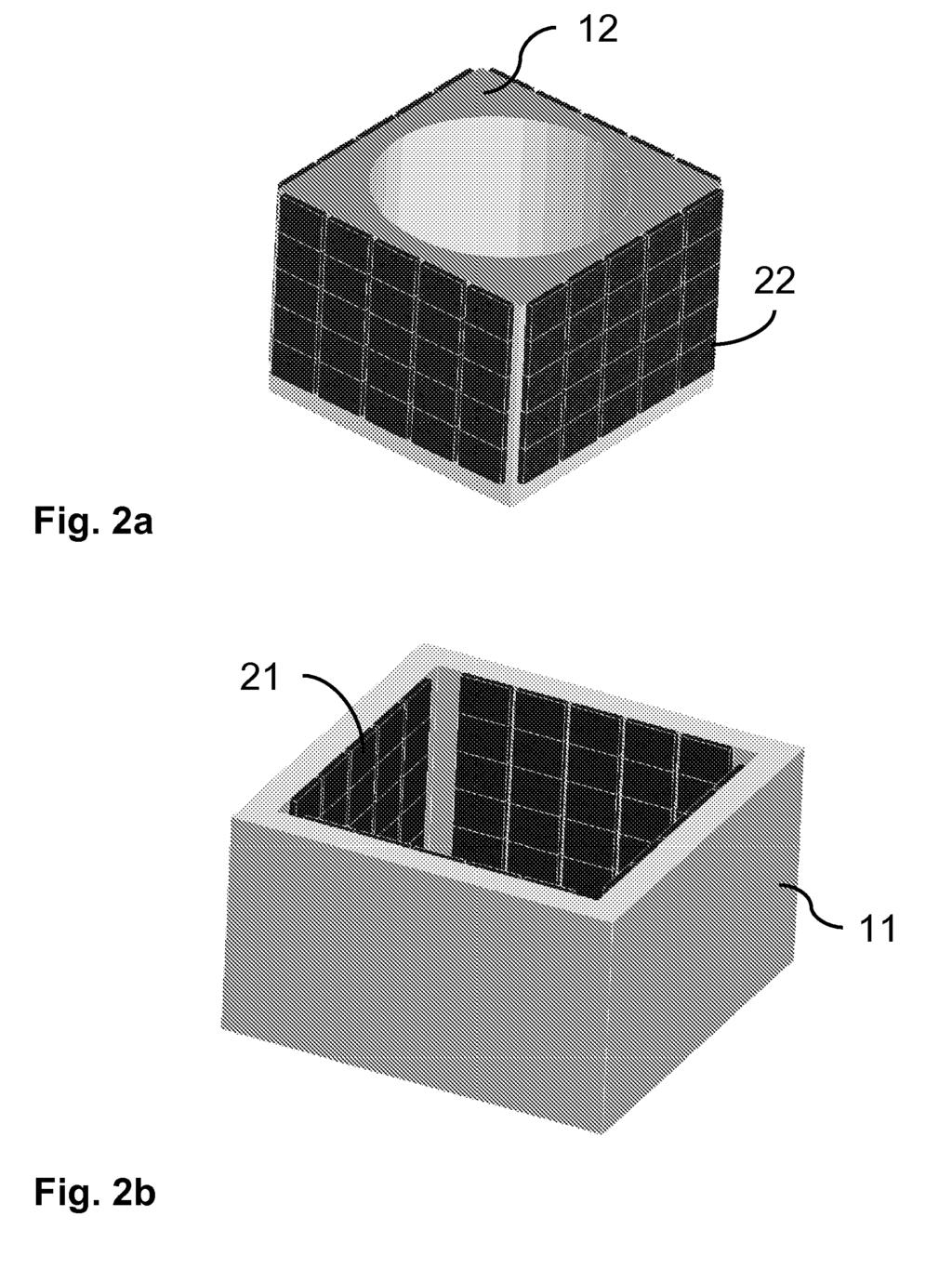
9 9
10 10
11 11
12 12
13 13
14 14
15 15
16 16
17 17
18 REFERENCES CITED IN THE DESCRIPTION This list of references cited by the applicant is for the reader s convenience only. It does not form part of the European patent document. Even though great care has been taken in compiling the references, errors or omissions cannot be excluded and the EPO disclaims all liability in this regard. Patent documents cited in the description US B [0005] 18
TEPZZ 89955_A T EP A2 (19) (11) EP A2 (12) EUROPEAN PATENT APPLICATION. (51) Int Cl.: G01R 15/20 ( )
 (11) EP A2 (12) EUROPEAN PATENT APPLICATION. (51) Int Cl.: G01R 15/20 ( )") (19) TEPZZ 899_A T (11) EP 2 899 1 A2 (12) EUROPEAN PATENT APPLICATION (43) Date of publication: 29.07.201 Bulletin 201/31 (1) Int Cl.: G01R 1/20 (2006.01) (21) Application number: 111708.3 (22) Date of
(19) TEPZZ 899_A T (11) EP 2 899 1 A2 (12) EUROPEAN PATENT APPLICATION (43) Date of publication: 29.07.201 Bulletin 201/31 (1) Int Cl.: G01R 1/20 (2006.01) (21) Application number: 111708.3 (22) Date of
TEPZZ A T EP A2 (19) (11) EP A2 (12) EUROPEAN PATENT APPLICATION. (51) Int Cl.: H02M 7/483 ( )
 (11) EP A2 (12) EUROPEAN PATENT APPLICATION. (51) Int Cl.: H02M 7/483 ( )") (19) TEPZZ 7849 6A T (11) EP 2 784 926 A2 (12) EUROPEAN PATENT APPLICATION (43) Date of publication: 01..14 Bulletin 14/40 (1) Int Cl.: H02M 7/483 (07.01) (21) Application number: 14162389.2 (22) Date
(19) TEPZZ 7849 6A T (11) EP 2 784 926 A2 (12) EUROPEAN PATENT APPLICATION (43) Date of publication: 01..14 Bulletin 14/40 (1) Int Cl.: H02M 7/483 (07.01) (21) Application number: 14162389.2 (22) Date
TEPZZ A_T EP A1 (19) (11) EP A1. (12) EUROPEAN PATENT APPLICATION published in accordance with Art.
 (11) EP A1. (12) EUROPEAN PATENT APPLICATION published in accordance with Art.") (19) TEPZZ 988 79A_T (11) EP 2 988 279 A1 (12) EUROPEAN PATENT APPLICATION published in accordance with Art. 13(4) EPC (43) Date of publication: 24.02.16 Bulletin 16/08 (21) Application number: 1478028.3
(19) TEPZZ 988 79A_T (11) EP 2 988 279 A1 (12) EUROPEAN PATENT APPLICATION published in accordance with Art. 13(4) EPC (43) Date of publication: 24.02.16 Bulletin 16/08 (21) Application number: 1478028.3
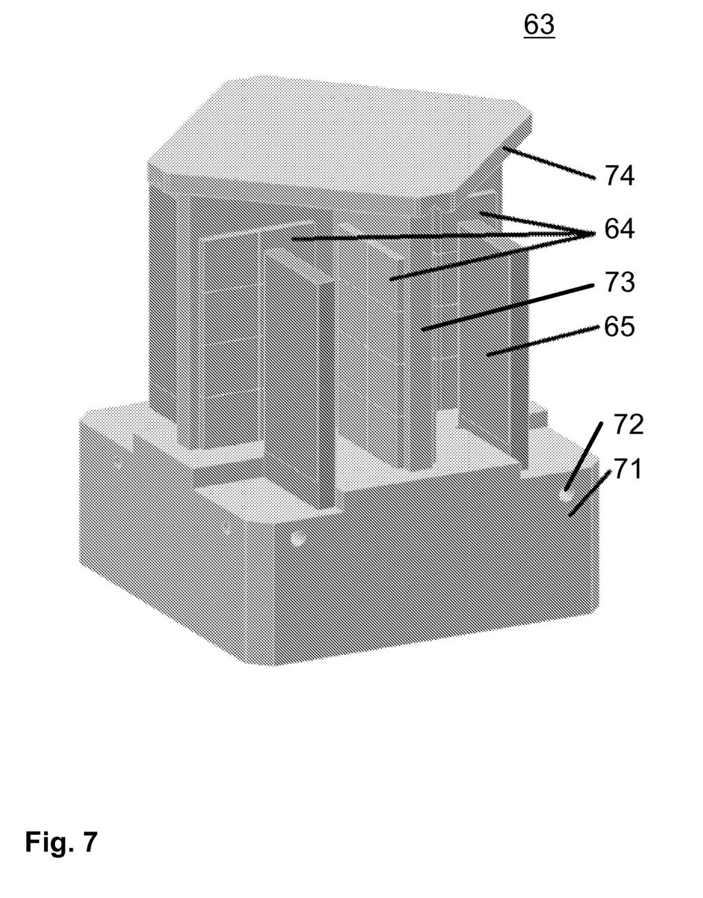
TEPZZ A_T EP A1 (19) (11) EP A1 (12) EUROPEAN PATENT APPLICATION. (51) Int Cl.:
 (11) EP A1 (12) EUROPEAN PATENT APPLICATION. (51) Int Cl.:") (19) TEPZZ 6 6697A_T (11) EP 2 626 697 A1 (12) EUROPEAN PATENT APPLICATION (43) Date of publication: 14.08.2013 Bulletin 2013/33 (1) Int Cl.: G01N 30/32 (2006.01) G01N 30/20 (2006.01) (21) Application
(19) TEPZZ 6 6697A_T (11) EP 2 626 697 A1 (12) EUROPEAN PATENT APPLICATION (43) Date of publication: 14.08.2013 Bulletin 2013/33 (1) Int Cl.: G01N 30/32 (2006.01) G01N 30/20 (2006.01) (21) Application
TEPZZ 6_Z6_ A_T EP A1 (19) (11) EP A1 (12) EUROPEAN PATENT APPLICATION. (51) Int Cl.:
 (11) EP A1 (12) EUROPEAN PATENT APPLICATION. (51) Int Cl.:") (19) TEPZZ 6_Z6_ A_T (11) EP 2 6 612 A1 (12) EUROPEAN PATENT APPLICATION (43) Date of publication: 03.07.2013 Bulletin 2013/27 (51) Int Cl.: G01N 27/333 (2006.01) G01N 27/416 (2006.01) (21) Application
(19) TEPZZ 6_Z6_ A_T (11) EP 2 6 612 A1 (12) EUROPEAN PATENT APPLICATION (43) Date of publication: 03.07.2013 Bulletin 2013/27 (51) Int Cl.: G01N 27/333 (2006.01) G01N 27/416 (2006.01) (21) Application
TEPZZ 95785_A_T EP A1 (19) (11) EP A1 (12) EUROPEAN PATENT APPLICATION
 (11) EP A1 (12) EUROPEAN PATENT APPLICATION") (19) TEPZZ 978_A_T (11) EP 2 97 81 A1 (12) EUROPEAN PATENT APPLICATION (43) Date of publication: 23.12. Bulletin /2 (21) Application number: 14172928. (1) Int Cl.: F28F 3/04 (06.01) F28F 3/08 (06.01) F28F
(19) TEPZZ 978_A_T (11) EP 2 97 81 A1 (12) EUROPEAN PATENT APPLICATION (43) Date of publication: 23.12. Bulletin /2 (21) Application number: 14172928. (1) Int Cl.: F28F 3/04 (06.01) F28F 3/08 (06.01) F28F
TEPZZ A_T EP A1 (19) (11) EP A1 (12) EUROPEAN PATENT APPLICATION. (51) Int Cl.: G01J 5/62 ( ) G01J 3/28 (2006.
 (11) EP A1 (12) EUROPEAN PATENT APPLICATION. (51) Int Cl.: G01J 5/62 ( ) G01J 3/28 (2006.") (19) TEPZZ 9474 A_T (11) EP 2 947 43 A1 (12) EUROPEAN PATENT APPLICATION (43) Date of publication: 2.11.1 Bulletin 1/48 (1) Int Cl.: G01J /62 (06.01) G01J 3/28 (06.01) (21) Application number: 1164674.2
(19) TEPZZ 9474 A_T (11) EP 2 947 43 A1 (12) EUROPEAN PATENT APPLICATION (43) Date of publication: 2.11.1 Bulletin 1/48 (1) Int Cl.: G01J /62 (06.01) G01J 3/28 (06.01) (21) Application number: 1164674.2
EP A1 (19) (11) EP A1 (12) EUROPEAN PATENT APPLICATION. (51) Int Cl.: B01D 9/00 ( )
 (11) EP A1 (12) EUROPEAN PATENT APPLICATION. (51) Int Cl.: B01D 9/00 ( )") (19) (12) EUROPEAN PATENT APPLICATION (11) EP 2 505 243 A1 (43) Date of publication: 03.10.2012 Bulletin 2012/40 (51) Int Cl.: B01D 9/00 (2006.01) (21) Application number: 12162017.3 (22) Date of filing:
(19) (12) EUROPEAN PATENT APPLICATION (11) EP 2 505 243 A1 (43) Date of publication: 03.10.2012 Bulletin 2012/40 (51) Int Cl.: B01D 9/00 (2006.01) (21) Application number: 12162017.3 (22) Date of filing:
*EP A1* EP A1 (19) (11) EP A1. (12) EUROPEAN PATENT APPLICATION published in accordance with Art.
 (11) EP A1. (12) EUROPEAN PATENT APPLICATION published in accordance with Art.") (19) Europäisches Patentamt European Patent Office Office européen des brevets *EP001610121A1* (11) (12) EUROPEAN PATENT APPLICATION published in accordance with Art. 158(3) EPC (43) Date of publication:
(19) Europäisches Patentamt European Patent Office Office européen des brevets *EP001610121A1* (11) (12) EUROPEAN PATENT APPLICATION published in accordance with Art. 158(3) EPC (43) Date of publication:
TEPZZ ZZ Z_ A_T EP A1 (19) (11) EP A1 (12) EUROPEAN PATENT APPLICATION
 (11) EP A1 (12) EUROPEAN PATENT APPLICATION") (19) TEPZZ ZZ Z_ A_T (11) EP 3 002 013 A1 (12) EUROPEAN PATENT APPLICATION (43) Date of publication: 06.04.16 Bulletin 16/14 (21) Application number: 14382379.7 (1) Int Cl.: A61L 9/ (06.01) A61L 9/22 (06.01)
(19) TEPZZ ZZ Z_ A_T (11) EP 3 002 013 A1 (12) EUROPEAN PATENT APPLICATION (43) Date of publication: 06.04.16 Bulletin 16/14 (21) Application number: 14382379.7 (1) Int Cl.: A61L 9/ (06.01) A61L 9/22 (06.01)
TEPZZ 6_8_ ZA_T EP A1 (19) (11) EP A1 (12) EUROPEAN PATENT APPLICATION. (51) Int Cl.:
 (11) EP A1 (12) EUROPEAN PATENT APPLICATION. (51) Int Cl.:") (19) TEPZZ 6_8_ ZA_T (11) EP 2 618 130 A1 (12) EUROPEAN PATENT APPLICATION (43) Date of publication: 24.07.13 Bulletin 13/30 (1) Int Cl.: G01N 21/ (06.01) G01N 21/77 (06.01) G01N 33/43 (06.01) (21) Application
(19) TEPZZ 6_8_ ZA_T (11) EP 2 618 130 A1 (12) EUROPEAN PATENT APPLICATION (43) Date of publication: 24.07.13 Bulletin 13/30 (1) Int Cl.: G01N 21/ (06.01) G01N 21/77 (06.01) G01N 33/43 (06.01) (21) Application
EP A1 (19) (11) EP A1 (12) EUROPEAN PATENT APPLICATION. (43) Date of publication: Bulletin 2011/06
 (11) EP A1 (12) EUROPEAN PATENT APPLICATION. (43) Date of publication: Bulletin 2011/06") (19) (12) EUROPEAN PATENT APPLICATION (11) EP 2 281 809 A1 (43) Date of publication: 09.02.2011 Bulletin 2011/06 (21) Application number: 09178846.3 (1) Int Cl.: C07C 231/24 (2006.01) C07C 237/46 (2006.01)
(19) (12) EUROPEAN PATENT APPLICATION (11) EP 2 281 809 A1 (43) Date of publication: 09.02.2011 Bulletin 2011/06 (21) Application number: 09178846.3 (1) Int Cl.: C07C 231/24 (2006.01) C07C 237/46 (2006.01)
TEPZZ 6 Z487A_T EP A1 (19) (11) EP A1 (12) EUROPEAN PATENT APPLICATION. (43) Date of publication: Bulletin 2013/31
 (11) EP A1 (12) EUROPEAN PATENT APPLICATION. (43) Date of publication: Bulletin 2013/31") (19) TEPZZ 6 Z487A_T (11) EP 2 620 487 A1 (12) EUROPEAN PATENT APPLICATION (43) Date of publication: 31.07.2013 Bulletin 2013/31 (21) Application number: 1313366.3 (1) Int Cl.: C11D 1/37 (2006.01) C11D
(19) TEPZZ 6 Z487A_T (11) EP 2 620 487 A1 (12) EUROPEAN PATENT APPLICATION (43) Date of publication: 31.07.2013 Bulletin 2013/31 (21) Application number: 1313366.3 (1) Int Cl.: C11D 1/37 (2006.01) C11D
Research Article Electromagnetic and Mechanical Characteristics Analysis of a Flat-Type Vertical-Gap Passive Magnetic Levitation Vibration Isolator
 Shock and Vibration Volume 6, Article ID 577, pages http://dx.doi.org/.55/6/577 Research Article Electromagnetic and Mechanical Characteristics Analysis of a Flat-Type Vertical-Gap Passive Magnetic Levitation
11/13/2018. The Hall Effect. The Hall Effect. The Hall Effect. Consider a magnetic field perpendicular to a flat, currentcarrying
 The Hall Effect Consider a magnetic field perpendicular to a flat, currentcarrying conductor. As the charge carriers move at the drift speed v d, they will experience a magnetic force F B = ev d B perpendicular
Consider a magnetic field perpendicular to a flat, currentcarrying
 The Hall Effect Consider a magnetic field perpendicular to a flat, currentcarrying conductor. As the charge carriers move at the drift speed v d, they will experience a magnetic force F B = ev d B perpendicular
Country
 Total A 36,3 31,1 B 33,8 36,9 37,4 D 41,4 D-W 41,6 37,7 40,7 42,4 D-E 28,2 36,9 36,8 DK 55,8 49,1 48,8 E 33,2 39,5 33,2 28,9 F 44,4 33,1 36,3 FIN 62,2 30,9 50,6 54,6 GB 26,1 26,2 27,1 GR 14,5 I 34,5 32,1
*EP A1* EP A1 (19) (11) EP A1 (12) EUROPEAN PATENT APPLICATION. (43) Date of publication: Bulletin 2004/22
 (11) EP A1 (12) EUROPEAN PATENT APPLICATION. (43) Date of publication: Bulletin 2004/22") (19) Europäisches Patentamt European Patent Office Office européen des brevets *EP0014222A1* (11) EP 1 422 2 A1 (12) EUROPEAN PATENT APPLICATION (43) Date of publication: 26.0.04 Bulletin 04/22 (1) Int
(19) Europäisches Patentamt European Patent Office Office européen des brevets *EP0014222A1* (11) EP 1 422 2 A1 (12) EUROPEAN PATENT APPLICATION (43) Date of publication: 26.0.04 Bulletin 04/22 (1) Int
Country
 Total EU-12 89,6 89,4 85,7 82,9 85,9 86,9 87,4 EU-15 89,6 85,7 83,1 86,2 87,0 87,5 EU-25 87,9 A 95,1 90,2 88,0 90,8 88,2 93,7 B 80,7 91,1 84,6 84,3 86,3 89,6 85,8 D 95,1 94,1 86,1 86,3 88,0 86,4 89,4 D-W
Chapter 12. Magnetism and Electromagnetism
 Chapter 12 Magnetism and Electromagnetism 167 168 AP Physics Multiple Choice Practice Magnetism and Electromagnetism SECTION A Magnetostatics 1. Four infinitely long wires are arranged as shown in the
Document Version Publisher s PDF, also known as Version of Record (includes final page, issue and volume numbers)
") 3-D analytical calculation of the torque between perpendicular magnetized magnets in magnetic suspensions Janssen, J.L.G.; Paulides, J.J.H.; Lomonova, E.A. Published in: IEEE Transactions on Magnetics
3-D analytical calculation of the torque between perpendicular magnetized magnets in magnetic suspensions Janssen, J.L.G.; Paulides, J.J.H.; Lomonova, E.A. Published in: IEEE Transactions on Magnetics
(12) United States Patent
 United States Patent") (12) United States Patent US007191654B2 (10) Patent No.: US 7,191,654 B2 Dwyer et al. (45) Date of Patent: Mar. 20, 2007 (54) METHODS AND SYSTEMS FOR ADJUSTING (56) References Cited MAGNETIC RETURN PATH
(12) United States Patent US007191654B2 (10) Patent No.: US 7,191,654 B2 Dwyer et al. (45) Date of Patent: Mar. 20, 2007 (54) METHODS AND SYSTEMS FOR ADJUSTING (56) References Cited MAGNETIC RETURN PATH
United States Patent [19]
![United States Patent [19]](/thumbs/76/73521136.jpg "United States Patent [19]") United States Patent [19] Murphy 111111111111111111111111111111111111111111111111111111111111111111111111111 US005479716A [11] Patent Number: 5,479,716 [4S] Date of Patent: Jan. 2, 1996 [S4] CAPACITIVE
United States Patent [19] Murphy 111111111111111111111111111111111111111111111111111111111111111111111111111 US005479716A [11] Patent Number: 5,479,716 [4S] Date of Patent: Jan. 2, 1996 [S4] CAPACITIVE
Chapter 27 Magnetism 1/20/ Magnets and Magnetic Fields Magnets and Magnetic Fields Magnets and Magnetic Fields
 Chapter 27 Magnetism Magnets have two ends poles called north and south. Like poles repel; unlike poles attract. However, if you cut a magnet in half, you don t get a north pole and a south pole you get
COPPER FOR BUSBARS CHAPTER 4: SHORT-CIRCUIT EFFECTS
 European Copper Institute COPPER FOR BUSBARS CHAPTER 4: SHORT-CIRCUIT EFFECTS David Chapman August 2011 ECI Available from www.leonardo-energy.org Document Issue Control Sheet Document Title: Publication
Chapter 4. Electrostatic Fields in Matter
 Chapter 4. Electrostatic Fields in Matter 4.1. Polarization 4.2. The Field of a Polarized Object 4.3. The Electric Displacement 4.4. Linear Dielectrics 4.5. Energy in dielectric systems 4.6. Forces on
United States Patent (19)
") United States Patent (19) Harrigan 54 LEVITATION DEVICE 76 Inventor: Roy M. Harrigan, Bromley Mountain Rd., Manchester, Vt. O54 21 22 63 51 (52) 58 Appl. No.: 105,239 Fed: Dec. 19, 1979 Related U.S. Application
United States Patent (19) Harrigan 54 LEVITATION DEVICE 76 Inventor: Roy M. Harrigan, Bromley Mountain Rd., Manchester, Vt. O54 21 22 63 51 (52) 58 Appl. No.: 105,239 Fed: Dec. 19, 1979 Related U.S. Application
Evolution Strategies for Optimizing Rectangular Cartograms
 Evolution Strategies for Optimizing Rectangular Cartograms Kevin Buchin 1, Bettina Speckmann 1, and Sander Verdonschot 2 1 TU Eindhoven, 2 Carleton University September 20, 2012 Sander Verdonschot (Carleton
EP A1 (19) (11) EP A1 (12) EUROPEAN PATENT APPLICATION. (43) Date of publication: Bulletin 2012/19
 (11) EP A1 (12) EUROPEAN PATENT APPLICATION. (43) Date of publication: Bulletin 2012/19") (19) (12) EUROPEAN PATENT APPLICATION (11) EP 2 40 336 A1 (43) Date of publication: 09.0.2012 Bulletin 2012/19 (21) Application number: 19081.8 (1) Int Cl.: C07C 41/6 (2006.01) C07C 43/30 (2006.01) C07C
(19) (12) EUROPEAN PATENT APPLICATION (11) EP 2 40 336 A1 (43) Date of publication: 09.0.2012 Bulletin 2012/19 (21) Application number: 19081.8 (1) Int Cl.: C07C 41/6 (2006.01) C07C 43/30 (2006.01) C07C
Magnetic Counterforce for Insertion Devices*
 SLAC-PUB-9594 October 2002 Magnetic Counterforce for Insertion Devices* Roger Carr Stanford Linear Accelerator Center, Stanford University, Stanford, CA 94309 Abstract In a standard insertion device, such
Chapter 27 Magnetism. Copyright 2009 Pearson Education, Inc.
 Chapter 27 Magnetism 27-1 Magnets and Magnetic Fields Magnets have two ends poles called north and south. Like poles repel; unlike poles attract. 27-1 Magnets and Magnetic Fields However, if you cut a
US A1 (19) United States (12) Patent Application Publication (10) Pub. No.: US 2006/ A1 St. Clair (43) Pub. Date: Jul.
 United States (12) Patent Application Publication (10) Pub. No.: US 2006/ A1 St. Clair (43) Pub. Date: Jul.") US 20060145019A1 (19) United States (12) Patent Application Publication (10) Pub. No.: US 2006/0145019 A1 St. Clair (43) Pub. Date: Jul. 6, 2006 (54) TRIANGULAR SPACECRAFT Publication Classi?cation (51)
US 20060145019A1 (19) United States (12) Patent Application Publication (10) Pub. No.: US 2006/0145019 A1 St. Clair (43) Pub. Date: Jul. 6, 2006 (54) TRIANGULAR SPACECRAFT Publication Classi?cation (51)
Two point charges, A and B, lie along a line separated by a distance L. The point x is the midpoint of their separation.
 Use the following to answer question 1. Two point charges, A and B, lie along a line separated by a distance L. The point x is the midpoint of their separation. 1. Which combination of charges would yield
Practice. Newton s 3 Laws of Motion. Recall. Forces a push or pull acting on an object; a vector quantity measured in Newtons (kg m/s²)
") Practice A car starts from rest and travels upwards along a straight road inclined at an angle of 5 from the horizontal. The length of the road is 450 m and the mass of the car is 800 kg. The speed of
Practice A car starts from rest and travels upwards along a straight road inclined at an angle of 5 from the horizontal. The length of the road is 450 m and the mass of the car is 800 kg. The speed of
(os) SSO. (10) Patent No.: US 6,779,290 B1. (45) Date of Patent: Aug. 24, (12) United States Patent (54) (75) (73)
 SSO. (10) Patent No.: US 6,779,290 B1. (45) Date of Patent: Aug. 24, (12) United States Patent (54) (75) (73)") (12) United States Patent HOutSma USOO677929OB1 (10) Patent No.: US 6,779,290 B1 (45) Date of Patent: Aug. 24, 2004 (54) (75) (73) (21) (22) (51) (52) (58) (56) SEMI PERMANENT BACKUP IRON SIGHT Inventor:
(12) United States Patent HOutSma USOO677929OB1 (10) Patent No.: US 6,779,290 B1 (45) Date of Patent: Aug. 24, 2004 (54) (75) (73) (21) (22) (51) (52) (58) (56) SEMI PERMANENT BACKUP IRON SIGHT Inventor:
The magnitude of this force is a scalar quantity called weight.
 Everyday Forces has direction The gravitational force (F g ) exerted on the ball by Earth is a vector directed toward the center of the earth. The magnitude of this force is a scalar quantity called weight.
PHYSICS. Chapter 29 Lecture FOR SCIENTISTS AND ENGINEERS A STRATEGIC APPROACH 4/E RANDALL D. KNIGHT
 PHYSICS FOR SCIENTISTS AND ENGINEERS A STRATEGIC APPROACH 4/E Chapter 29 Lecture RANDALL D. KNIGHT Chapter 29 The Magnetic Field IN THIS CHAPTER, you will learn about magnetism and the magnetic field.
Review: Newton s Laws
 More force was needed to stop the rock Review: Newton s Laws F r 1 F r F r 3 F r 4 2 Newton s First Law The velocity of an object does not change unless a force acts on the object Newton s Second Law:
week 8 The Magnetic Field
 week 8 The Magnetic Field General Principles General Principles Applications Start with magnetic forces on moving charges and currents A positive charge enters a uniform magnetic field as shown. What is
Ch 6 Using Newton s Laws. Applications to mass, weight, friction, air resistance, and periodic motion
 Ch 6 Using Newton s Laws Applications to mass, weight, friction, air resistance, and periodic motion Newton s 2 nd Law Applied Galileo hypothesized that all objects gain speed at the same rate (have the
MAGNETIC FIELDS CHAPTER 21
 MAGNETIC FIELDS CHAPTER 21 1. A magnetic field may exist at a point as a result of moving charged particle 2. When a tiny bar magnet is suspended horizontally from its center, it lines up along the north
6.013 Lecture 12: Magnetic Forces and Devices
 6.013 Lecture 12: Magnetic Forces and Devices A. Overview Magnetic forces are central to a wide array of actuators and sensors. These forces can be calculated using either energy methods or the Lorentz
Writing Patent Specifications
 Writing Patent Specifications Japan Patent Office Asia-Pacific Industrial Property Center, JIPII 2013 Collaborator: Shoji HADATE, Patent Attorney, Intellectual Property Office NEXPAT CONTENTS Page 1. Patent
33 Electric Fields and Potential. An electric field is a storehouse of energy.
 An electric field is a storehouse of energy. The space around a concentration of electric charge is different from how it would be if the charge were not there. If you walk by the charged dome of an electrostatic
EQUILIBRIUM OBJECTIVES PRE-LECTURE
 27 FE3 EQUILIBRIUM Aims OBJECTIVES In this chapter you will learn the concepts and principles needed to understand mechanical equilibrium. You should be able to demonstrate your understanding by analysing
36 Magnetism. A moving electric charge is surrounded by a magnetic field.
 A moving electric charge is surrounded by a magnetic field. Electricity and magnetism were regarded as unrelated phenomena until it was noticed that an electric current caused the deflection of the compass
Pushes and Pulls. Example- an apple falling on a tree exerts a downward force with a magnitude of about 1 newton.
 What are Forces? Pushes and Pulls Force- a push or pull that acts on an object. Forces make a moving object speed up, slow down, or change direction. Forces have both magnitude and direction. Magnitude
A moving electric charge is surrounded by a magnetic field Magnetic Poles
 A moving electric charge is surrounded by a magnetic field. Electricity and magnetism were regarded as unrelated phenomena until it was noticed that an electric current caused the deflection of the compass
Chapter 27 Magnetism. Copyright 2009 Pearson Education, Inc.
 Chapter 27 Magnetism 27-1 Magnets and Magnetic Fields Magnets have two ends poles called north and south. Like poles repel; unlike poles attract. 27-1 Magnets and Magnetic Fields However, if you cut a
Physics for Scientists and Engineers. Chapter 5 Force and Motion
 Physics for Scientists and Engineers Chapter 5 Force and Motion Spring, 2008 Ho Jung Paik Force Forces are what cause any change in the velocity of an object The net force is the vector sum of all the
Chapter 8. Potential Energy & Conservation of Energy
 Chapter 8 Potential Energy & Conservation of Energy 8.1 Potential Energy Technically, potential energy is energy that can be associated with the configuration (arrangement) of a system of objects that
Vector Mechanics: Statics
 PDHOnline Course G492 (4 PDH) Vector Mechanics: Statics Mark A. Strain, P.E. 2014 PDH Online PDH Center 5272 Meadow Estates Drive Fairfax, VA 22030-6658 Phone & Fax: 703-988-0088 www.pdhonline.org www.pdhcenter.com
PHYSICS. Chapter 5 Lecture FOR SCIENTISTS AND ENGINEERS A STRATEGIC APPROACH 4/E RANDALL D. KNIGHT Pearson Education, Inc.
 PHYSICS FOR SCIENTISTS AND ENGINEERS A STRATEGIC APPROACH 4/E Chapter 5 Lecture RANDALL D. KNIGHT Chapter 5 Force and Motion IN THIS CHAPTER, you will learn about the connection between force and motion.
Virbations and Waves
 Virbations and Waves 1.1 Observe and find a pattern Try the following simple experiments and describe common patterns concerning the behavior of the block. (a) Fill in the table that follows. Experiment
LECTURE 12 FRICTION, STRINGS & SPRINGS. Instructor: Kazumi Tolich
 LECTURE 12 FRICTION, STRINGS & SPRINGS Instructor: Kazumi Tolich Lecture 12 2! Reading chapter 6-1 to 6-4! Friction " Static friction " Kinetic friction! Strings! Pulleys! Springs Origin of friction 3!!
Experiment 19: The Current Balance
 Experiment 19: The Current Balance Figure 19.1: Current Balance Arrangement for Varying Current or Length From Left to Right: Power Supply, Current Balance Assembly, Ammeter (20A DCA scale, 20A jack).
(12) Patent Application Publication (10) Pub. No.: US 2001/ A1
 Patent Application Publication (10) Pub. No.: US 2001/ A1") US 2001 OO10407A1 (19) United States (12) Patent Application Publication (10) Pub. No.: US 2001/0010407 A1 Ker et al. (43) Pub. Date: (54) LOW-CAPACITANCE BONDING PAD FOR (30) Foreign Application Priority
US 2001 OO10407A1 (19) United States (12) Patent Application Publication (10) Pub. No.: US 2001/0010407 A1 Ker et al. (43) Pub. Date: (54) LOW-CAPACITANCE BONDING PAD FOR (30) Foreign Application Priority
AA. *alt24& DS. (12) United States Patent US 6,607,370 B2. Aug. 19, (45) Date of Patent: (10) Patent No.: Fukamachi et al.
 United States Patent US 6,607,370 B2. Aug. 19, (45) Date of Patent: (10) Patent No.: Fukamachi et al.") (12) United States Patent Fukamachi et al. USOO660737OB2 (10) Patent No.: (45) Date of Patent: US 6,607,370 B2 Aug. 19, 2003 (54) MAGNETIC PUMP (75) Inventors: Masatoshi Fukamachi, Wako (JP); Osamu Sato,
(12) United States Patent Fukamachi et al. USOO660737OB2 (10) Patent No.: (45) Date of Patent: US 6,607,370 B2 Aug. 19, 2003 (54) MAGNETIC PUMP (75) Inventors: Masatoshi Fukamachi, Wako (JP); Osamu Sato,
Work and Energy. computer masses (200 g and 500 g) If the force is constant and parallel to the object s path, work can be calculated using
 If the force is constant and parallel to the object s path, work can be calculated using") Work and Energy OBJECTIVES Use a Motion Detector and a Force Sensor to measure the position and force on a hanging mass, a spring, and a dynamics cart. Determine the work done on an object using a force
Work and Energy OBJECTIVES Use a Motion Detector and a Force Sensor to measure the position and force on a hanging mass, a spring, and a dynamics cart. Determine the work done on an object using a force
(12) Patent Application Publication (10) Pub. No.: US 2016/ A1
 Patent Application Publication (10) Pub. No.: US 2016/ A1") (19) United States US 2016O247659A1 (12) Patent Application Publication (10) Pub. No.: US 2016/0247659 A1 OH et al. (43) Pub. Date: Aug. 25, 2016 (54) ELECTROSTATIC QUADRUPOLE Publication Classification
(19) United States US 2016O247659A1 (12) Patent Application Publication (10) Pub. No.: US 2016/0247659 A1 OH et al. (43) Pub. Date: Aug. 25, 2016 (54) ELECTROSTATIC QUADRUPOLE Publication Classification
Glossary Innovative Measurement Solutions
 Glossary GLOSSARY OF TERMS FOR TRANSDUCERS, LOAD CELLS AND WEIGH MODULES This purpose of this document is to provide a comprehensive, alphabetical list of terms and definitions commonly employed in the
Theme 2 - PHYSICS UNIT 2 Forces and Moments. A force is a push or a pull. This means that whenever we push or pull something, we are doing a force.
 Forces A force is a push or a pull. This means that whenever we push or pull something, we are doing a force. Forces are measured in Newtons (N) after the great physicist Sir Isaac Newton. The instrument
Phys102 Lecture 16/17 Magnetic fields
 Phys102 Lecture 16/17 Magnetic fields Key Points Electric Currents Produce Magnetic Fields Force on an Electric Current in a Magnetic Field; Definition of B Force on an Electric Charge Moving in a Magnetic
Paponneau (45) Date of Patent: Sep. 27, 2016
 Date of Patent: Sep. 27, 2016") (12) United States Patent USOO9453899B2 (10) Patent No.: US 9.453,899 B2 Paponneau (45) Date of Patent: Sep. 27, 2016 (54) SYSTEM FOR EFFECTING THE (52) U.S. Cl. ROTATIONAL MOVEMENT OF A SOLAR CPC... G0IS
(12) United States Patent USOO9453899B2 (10) Patent No.: US 9.453,899 B2 Paponneau (45) Date of Patent: Sep. 27, 2016 (54) SYSTEM FOR EFFECTING THE (52) U.S. Cl. ROTATIONAL MOVEMENT OF A SOLAR CPC... G0IS
(12) Patent Application Publication (10) Pub. No.: US 2008/ A1. Chung et al. (43) Pub. Date: Jan. 24, 2008
 Patent Application Publication (10) Pub. No.: US 2008/ A1. Chung et al. (43) Pub. Date: Jan. 24, 2008") US 2008.0017293A1 (19) United States (12) Patent Application Publication (10) Pub. No.: US 2008/0017293 A1 Chung et al. (43) Pub. Date: Jan. 24, 2008 (54) AUTOMATICLEVEL ADJUSTMENT FOR Publication Classification
US 2008.0017293A1 (19) United States (12) Patent Application Publication (10) Pub. No.: US 2008/0017293 A1 Chung et al. (43) Pub. Date: Jan. 24, 2008 (54) AUTOMATICLEVEL ADJUSTMENT FOR Publication Classification
PHYSICS. Chapter 5 Lecture FOR SCIENTISTS AND ENGINEERS A STRATEGIC APPROACH 4/E RANDALL D. KNIGHT Pearson Education, Inc.
 PHYSICS FOR SCIENTISTS AND ENGINEERS A STRATEGIC APPROACH 4/E Chapter 5 Lecture RANDALL D. KNIGHT Chapter 5 Force and Motion IN THIS CHAPTER, you will learn about the connection between force and motion.
Chapter Four Holt Physics. Forces and the Laws of Motion
 Chapter Four Holt Physics Forces and the Laws of Motion Physics Force and the study of dynamics 1.Forces - a. Force - a push or a pull. It can change the motion of an object; start or stop movement; and,
Research Article A New Type of Magnetic Actuator Capable of Wall-Climbing Movement Using Inertia Force
 Engineering Volume 14, Article ID 93178, 6 pages http://dx.doi.org/1.1155/14/93178 Research Article A New Type of Magnetic Actuator Capable of Wall-Climbing Movement Using Inertia Force H. Yaguchi, S.
Name: Class: Date: AP Physics Spring 2012 Q6 Practice. Multiple Choice Identify the choice that best completes the statement or answers the question.
 ame: Class: Date: ID: A AP Physics Spring 2012 Q6 Practice Multiple Choice Identify the choice that best completes the statement or answers the question. 1. (2 points) A potential difference of 115 V across
Lecture T2 The Pendulum-Based Start Gate (US 8,016,639 B2)
") 1 Lecture T2 The Pendulum-Based Start Gate (US 8,016,639 B2) INTRODUCTION Literally millions of Pinewood Derby races have been run since the inception of the race in 1953, mostly by Cub Scouts and their
1 Lecture T2 The Pendulum-Based Start Gate (US 8,016,639 B2) INTRODUCTION Literally millions of Pinewood Derby races have been run since the inception of the race in 1953, mostly by Cub Scouts and their
FLOW-THROUGH CAPACITOR ASSEMBLY FOR THE TREATMENT OF A. Field of application
 FLOW-THROUGH CAPACITOR ASSEMBLY FOR THE TREATMENT OF A FLUID Field of application The present invention regards a flow-through capacitor assembly for the treatment of a fluid, according to the preamble
The Concept of Force Newton s First Law and Inertial Frames Mass Newton s Second Law The Gravitational Force and Weight Newton s Third Law Analysis
 The Laws of Motion The Concept of Force Newton s First Law and Inertial Frames Mass Newton s Second Law The Gravitational Force and Weight Newton s Third Law Analysis Models using Newton s Second Law Forces
Overview of numbers submitted for Statistics on Pending Mutual Agreement Procedures (MAPs) under the Arbitration Convention (AC) at the End of 2017
 under the Arbitration Convention (AC) at the End of 2017") EUROPEAN COMMISSION DIRECTORATE-GENERAL TAXATION AND CUSTOMS UNION Direct taxation, Tax Coordination, Economic Analysis and Evaluation Direct Tax Policy & Cooperation Brussels, September 2018 Taxud/D2
EUROPEAN COMMISSION DIRECTORATE-GENERAL TAXATION AND CUSTOMS UNION Direct taxation, Tax Coordination, Economic Analysis and Evaluation Direct Tax Policy & Cooperation Brussels, September 2018 Taxud/D2
21 MAGNETIC FORCES AND MAGNETIC FIELDS
 CHAPTER 1 MAGNETIC FORCES AND MAGNETIC FIELDS ANSWERS TO FOCUS ON CONCEPTS QUESTIONS 1 (d) Right-Hand Rule No 1 gives the direction of the magnetic force as x for both drawings A and B In drawing C, the
Magnetism. Permanent magnets Earth s magnetic field Magnetic force Motion of charged particles in magnetic fields
 Magnetism Permanent magnets Earth s magnetic field Magnetic force Motion of charged particles in magnetic fields Copyright The McGraw-Hill Companies, Inc. Permission required for reproduction or display.
Magnetism S8P5: Obtain, evaluate, and communicate information about gravity, electricity, and magnetism as major forces acting in nature.
 Magnetism S8P5: Obtain, evaluate, and communicate information about gravity, electricity, and magnetism as major forces acting in nature. A. Construct an argument using evidence to support the claim that
Electrics. Electromagnetism
 Electrics Electromagnetism Electromagnetism Magnetism is associated with charges in motion (currents): microscopic currents in the atoms of magnetic materials. macroscopic currents in the windings of an
US 9,214,722 B2 Dec. 15, 2015
 I lllll llllllll Ill lllll lllll lllll lllll lllll 111111111111111111111111111111111 US009214 722B2 c12) United States Patent Georgakopoulos et al. (IO) Patent No.: (45) Date of Patent: US 9,214,722 B2
Dynamics: Forces and Newton s Laws of Motion
 Lecture 7 Chapter 5 Physics I Dynamics: Forces and Newton s Laws of Motion Course website: http://faculty.uml.edu/andriy_danylov/teaching/physicsi Today we are going to discuss: Chapter 5: Force, Mass:
End-of-Chapter Exercises
 End-of-Chapter Exercises Exercises 1 12 are primarily conceptual questions, designed to see whether you understand the main concepts of the chapter. 1. A charged particle is moving with a constant velocity
Chapter 4. Forces and Newton s Laws of Motion. continued
 Chapter 4 Forces and Newton s Laws of Motion continued Quiz 3 4.7 The Gravitational Force Newton s Law of Universal Gravitation Every particle in the universe exerts an attractive force on every other
Optimization of two-dimensional permanent magnet arrays for diamagnetic levitation
 Optimization of two-dimensional permanent magnet arrays for diamagnetic levitation Roland Moser, François Barrot, Jan Sandtner, Hannes Bleuler Laboratory of Robotic Systems Swiss Federal Institute of Technology,
Tridib s Physics Tutorials. NCERT-XII / Unit- 4 Moving charge and magnetic field
 MAGNETIC FIELD DUE TO A CURRENT ELEMENT The relation between current and the magnetic field, produced by it is magnetic effect of currents. The magnetic fields that we know are due to currents or moving
CHAPTER 20 Magnetism
 CHAPTER 20 Magnetism Units Magnets and Magnetic Fields Electric Currents Produce Magnetic Fields Force on an Electric Current in a Magnetic Field; Definition of B Force on Electric Charge Moving in a Magnetic
# Ans Workings / Remarks
 # Ans Workings / Remarks 1 A The positive zero error is +0.03 mm. The reading is 1.84 mm. Thus, final reading = 1.84 (+0.03) = 1.81 mm 2 A We can use parallelogram of forces to determine the final resultant
SPH 4U: Unit 3 - Electric and Magnetic Fields
 Name: Class: _ Date: _ SPH 4U: Unit 3 - Electric and Magnetic Fields Modified True/False (1 point each) Indicate whether the statement is true or false. If false, change the identified word or phrase to
Exam 1 Stats: Average: 60% Approximate letter grade? Add 10%-12% (This is not a curve) This takes into account the HW, Lab, and Grade Replacement.
 This takes into account the HW, Lab, and Grade Replacement.") Lec 11 Return Exam1 Intro Forces Tuesday, February 19, 2019 1:52 PM Exam 1 Stats: Average: 60% Approximate letter grade? Add 10%-12% (This is not a curve) This takes into account the HW, Lab, and Grade
Lec 11 Return Exam1 Intro Forces Tuesday, February 19, 2019 1:52 PM Exam 1 Stats: Average: 60% Approximate letter grade? Add 10%-12% (This is not a curve) This takes into account the HW, Lab, and Grade
(12) United States Patent (10) Patent No.: US 6,508,132 B1. Lohr et al. (45) Date of Patent: Jan. 21, 2003
 United States Patent (10) Patent No.: US 6,508,132 B1. Lohr et al. (45) Date of Patent: Jan. 21, 2003") USOO6508132B1 (12) United States Patent (10) Patent No.: US 6,508,132 B1 Lohr et al. (45) Date of Patent: Jan. 21, 2003 (54) DYNAMIC LOAD CELL APPARATUS 4,478,086 A * 10/1984 Gram... 73/781 5,739,411 A
USOO6508132B1 (12) United States Patent (10) Patent No.: US 6,508,132 B1 Lohr et al. (45) Date of Patent: Jan. 21, 2003 (54) DYNAMIC LOAD CELL APPARATUS 4,478,086 A * 10/1984 Gram... 73/781 5,739,411 A
PHYSICS 222 Fall 2009 EXAM 1: October 1, :00pm 10:00pm
 PHYSICS 222 Fall 2009 EXAM 1: October 1, 2009 8:00pm 10:00pm Name (printed): Recitation Instructor: Section # INSTRUCTIONS: This exam contains 25 multiple-choice questions, plus two extra-credit questions,
GRIPs. Overview Andrea Ćirlićová Business Area Manager, System Development
 GRIPs Overview 2013 Andrea Ćirlićová Business Area Manager, System Development 6 th TYNDP Workshop, Brussels -- 15 November 2012 GRIPs GRIPs are the regional interlink between Union-wide TYNDP and national
Unit 2: Simple Harmonic Motion (SHM)
") Unit 2: Simple Harmonic Motion (SHM) THE MOST COMMON FORM OF MOTION FALL 2015 Objectives: Define SHM specifically and give an example. Write and apply formulas for finding the frequency f, period T, w
Unit 2: Simple Harmonic Motion (SHM) THE MOST COMMON FORM OF MOTION FALL 2015 Objectives: Define SHM specifically and give an example. Write and apply formulas for finding the frequency f, period T, w
Static Equilibrium and Torque
 10.3 Static Equilibrium and Torque SECTION OUTCOMES Use vector analysis in two dimensions for systems involving static equilibrium and torques. Apply static torques to structures such as seesaws and bridges.
The general rules of statics (as applied in solid mechanics) apply to fluids at rest. From earlier we know that:
 apply to fluids at rest. From earlier we know that:") ELEMENTARY HYDRAULICS National Certificate in Technology (Civil Engineering) Chapter 2 Pressure This section will study the forces acting on or generated by fluids at rest. Objectives Introduce the concept
ELEMENTARY HYDRAULICS National Certificate in Technology (Civil Engineering) Chapter 2 Pressure This section will study the forces acting on or generated by fluids at rest. Objectives Introduce the concept
Intermediate Physics PHYS102
 Intermediate Physics PHYS102 Dr Richard H. Cyburt Assistant Professor of Physics My office: 402c in the Science Building My phone: (304) 384-6006 My email: rcyburt@concord.edu My webpage: www.concord.edu/rcyburt
ELECTROMAGNETISM The study of the relationship between electricity and magnetism is called
 ELECTROMAGNETISM The study of the relationship between electricity and magnetism is called Electromagnetism Before, 1819 it was believed that there was no connection between electricity and magnetism.
General Physics I Spring Forces and Newton s Laws of Motion
 General Physics I Spring 2011 Forces and Newton s Laws of Motion 1 Forces and Interactions The central concept in understanding why things move is force. If a tractor pushes or pulls a trailer, the tractor
MULTIPLE CHOICE. Choose the one alternative that best completes the statement or answers the question.
 Exam Name MULTIPLE CHOICE. Choose the one alternative that best completes the statement or answers the question. 1) You are standing in a moving bus, facing forward, and you suddenly fall forward as the
Static equilibrium. Objectives. Physics terms. Assessment. Brainstorm. Equations 6/3/14
 Static equilibrium Objectives State the conditions of static equilibrium in terms of forces and torques. Draw a free-body diagram of a lever showing all forces. Use the condition of equilibrium to solve
DEVELOPMENT OF A NOVEL ACTIVE ISOLATION CONCEPT 1
 DEVELOPMENT OF A NOVEL ACTIVE ISOLATION CONCEPT 1 Michiel J. Vervoordeldonk, Theo A.M. Ruijl, Rob M.G. Rijs Philips Centre for Industrial Technology, PO Box 518, 5600 MD Eindhoven, The Netherlands 2 1
3/10/2019. What Is a Force? What Is a Force? Tactics: Drawing Force Vectors
 What Is a Force? A force acts on an object. A force requires an agent, something that acts on the object. If you throw a ball, your hand is the agent or cause of the force exerted on the ball. A force