AO system Design: Astronomy Olivier Guyon (University of Arizona / Subaru Telescope)
|
|
|
- Priscilla Spencer
- 5 years ago
- Views:
Transcription
")
1 AO system Design: Astronomy Olivier Guyon (University of Arizona / Subaru Telescope) guyon@naoj.org
2 This lecture: Will not discuss detailed optical designs, mechanical designs, hardware choices, computer algorithms (covered in other lectures, often specific to some AO systems, easy to get lost in details and miss big picture...) The main goals are to explore fundamental AO strategies, compare them, understand how/why/when they work or don't work, explore Telescope / AO system / instruments relationships This course won't teach you how to build an AO system, but it will help you figure out what kind of AO system you might build for a specific application & what kind of problems will need to be solved
3 Useful references Adaptive Optics in Astronomy (2004), by Francois Roddier (Editor), Cambridge University Press Adaptive Optics for Astronomical Telescopes (1998), by John W. Hardy, Oxford University Press 3
4 Outline Astronomical AO system diversity Main challenges / error budget terms in astronomical AO systems Wavefront sensing strategy Optical/mechanical design considerations From photons to DM commands: making it all work nicely together
5 Outline Astronomical AO system diversity Main challenges / error budget terms in astronomical AO systems Wavefront sensing strategy Optical/mechanical design considerations From photons to DM commands: making it all work nicely together
 Multi Conjugate AO (MCAO) AO loop speed 10 1 >1 DM needed Multi Object AO (MOAO)")
6 Wavefront Error (nm) Easier 100 nm High contrast Extreme-AO 10 nm 0 Narrow field visible AO Narrow field NGS in near-ir Low order AO Narrow field LGS in near-ir 1 guide star OK > 1 guide star needed usually also >1 LGS # of DM actuators # of WFS elements Field of view Ground-layer AO Laser Tomography AO (LTAO) Multi Conjugate AO (MCAO) AO loop speed 10 1 >1 DM needed Multi Object AO (MOAO) Optics size, optical layout complexity Need more photons 1 DM OK Challenging 6
 Gemini currently developing MCAO system")

7 Multi-Conjugate AO (MCAO) Results from ESO s MCAO demonstrator (MAD) Gemini currently developing MCAO system Strehl maps on the right show image quality is high over a wide field of view (black crosses show position of guide stars) 7
8 The MMT multi-laser Ground Layer AO (GLAO) system MMT results: M3 globular cluster Open loop, K s filter, seeing 0.70 Closed loop GLAO, K s filter, seeing 0.30 Logarithmic scale Logarithmic scale


9 The MMT multi-laser Ground Layer AO (GLAO) system MMT results: M3 globular cluster Open loop, K s filter, seeing 0.70 Closed loop GLAO, K s filter, seeing 0.30 Logarithmic scale Logarithmic scale
 Subaru")

10 Extreme-AO Gemini Planet Imager SPHERE (ESO) Subaru CExAO system Also under study: space-based ExAO systems 9
11 Outline Astronomical AO system diversity Main challenges / error budget terms in astronomical AO systems Wavefront sensing strategy Optical/mechanical design considerations From photons to DM commands: making it all work nicely together References:
12 Fundamental wavefront error budget terms : 1 Fitting error 2 Speed 3 Limited # of photons 4 AO guide star size & structure, sky background 5 Non-common path errors - chromaticity - cone effect (LGS) & anisoplanetism 6 Calibration, nasty practical things - vibrations, instabilities between control loops - DM hysteresis / poor calibration (generally not too serious in closed loop) Useful references: Adaptive Optics in Astronomy (2004), by Francois Roddier (Editor), Cambridge University Press Adaptive Optics for Astronomical Telescopes (1998), by John W. Hardy, Oxford University Press
13 Wavefront error budget Wavefront error σ is in radian in all equations. Wavefront variance σ 2 is additive (no correlation between different error sources), and the wavefront error budget is built by adding σ 2 terms. WF error (m) = λ x σ / (2 π) Strehl ratio ~ e -σ 2 Useful references: Adaptive Optics in Astronomy (2004), by Francois Roddier (Editor), Cambridge University Press Adaptive Optics for Astronomical Telescopes (1998), by John W. Hardy, 12 Oxford University Press

14 1. Fitting error Assuming that the wavefront error is perfectly known, how well can the deformable mirror(s) correct it? Wavefront errors from atmospheric turbulence in sq. radian σ 2 = 1.03 (D/r 0 ) 5/3 Kolmogorov turbulence + Vibrations, telescope guiding errors + Aberrations from optical elements (primary mirror, large number of small mirrors) + DM shape at rest
15 1. Fitting error Need enough stroke on the actuators σ 2 = 1.03 (D/r 0 ) 5/3 (unit = radian) Larger D -> more stroke needed (also: faster system -> more stroke needed) Most of the power is in tip-tilt: It is helpful to have a dedicated tip-tilt mirror, or mount the DM on a tip-tilt mount On many DMs, interactuator stroke < overall stroke DM stroke needs to be looked at as a function of spatial frequency eg: in a curvature DM, radius of curvature decreases as the number of actuators increases Is easier than
16 1. Fitting error Need enough actuators to fit the wavefront D = telescope diameter, N = number of actuators d = sqrt(d 2 /N) = actuator size If we assume each actuator does perfect piston correction (but no tip/tilt), WF error variance in sq. radian is: σ 2 = 1.03 (d/r 0 ) 5/3 = 1.03 (D/r 0 ) 5/3 N -5/6 If we assume continuous facesheet, σ 2 ~ 0.3 (D/r 0 ) 5/3 N -5/6 D = 8 m, r 0 = 0.8 m (0.2 m in visible = 0.8 m at 1.6 micron) Diffraction limit requires ~ N = 24 In fact, exact DM geometry & influence functions are needed to estimate fitting error
17 1. Fitting error & field of view Need enough actuators to fit the wavefront for over a nonzero field of view Two equivalent views of the problem: - Wavefront changes across the field of view (MOAO) - Several layers in the atmosphere need to be corrected (MCAO) If we assume perfect on-axis correction, and a single turbulent layer at altitude h, the variance (sq. radian) is : σ 2 = 1.03 (α/θ 0 ) 5/3 Where α is the angle to the optical axis, θ 0 is the isoplanatic angle: θ 0 = 0.31 (r 0 /h) α h D = 8 m, r 0 = 0.8 m, h = 5 km -> θ 0 = 10 To go beyond the isoplanatic angle: more DMs needed (but no need for more actuators per DM).
18 2. Speed Assuming perfect DMs and wavefront knowledge, how does performance decrease as the correction loop slows down? Assuming pure time delay t σ 2 = (t/t 0 ) 5/3 t 0 = coherence time Greenwood time delay = r 0 /v v = 10 m/s r 0 = 0.15 m (visible) 0.8 m (K band) t 0 = 4.71 ms (visible) 25 ms (K band) Assuming that sampling frequency should be ~ 10x bandwidth for diffraction-limited system (1 rad error in wavefront): sampling frequency = 400 Hz for K band for extreme-ao system (0.1 rad error): sampling frequency = 6 khz for K band
19 -> High speed means fewer photons / sample need high SNR in WFS (optimal use of photons) -> need fast hardware (see below) - DM: good time response, low vibration - Detector: fast readout / low readout noise - computer, software & electronics -> Clever, predictive control can help a lot anything that could be predicted should be! Collect photons Compute DM command Move DM Readout + move data to memory
20 3. Limited # of photons from stars (per unit of time) With a fixed finite photon arrival rate, how well can I measure the wavefront (speed vs. SNR)? Longer WFS exposure time -> better SNR but more time lag mv=15 -> 400 ph/ms on 8m pupil in 0.5 μm band & 20% efficiency Example 1: General purpose NGS system Goal: achieve diffraction limited performance over much of the sky 40% Star brighter than mv density ~ 9e-4 exp(0.9 mv) per sq. deg (galactic pole) ref: Parenti & Sasiela, 1994 Within a 20 radius: 0% mv=13 mv=17
21 mv=8 -> 2.5e5 ph/ms on 8m pupil in 0.5 micron band & 20% efficiency Example 2: Extreme-AO system Goal: Achieve exquisite wavefront correction on selected bright stars Running speed = 5 khz (see speed section before) 2000 actuators 25 photons / actuators / sampling time 6 photon / pixel if 2x2 Shack Hartmann cells are used with no readout noise, ~ 0.2 rad phase error per actuator at best.
22 Limited # of photons will push system design into: -> high efficiency WFS: good at converting OPD error into signal (if possible, choose shorter wavelength) -> high throughput (fewer optics), good detector (low readout noise) -> WFS which works in broad band for NGS -> bright laser for LGS, small angular size LGS -> multiple guide stars
23 4. AO guide star size & structure, sky background Extended targets means lower WFS efficiency and/or WFS failure This problem is very WFS-dependent (some WFSs cannot deal with extended sources) - Laser guide star is typically 1 or more, and elongated - NGS: atmospheric refraction can be serious -> Atmospheric Dispersion Compensator (ADC) is often essential in the WFS - frequent problem in Solar system observations - double stars can be a problem Sky background: for faint guide stars, moonlight is a concern
24 5. Non-common path errors - anisoplanatism (also discussed earlier in fitting error) Due to angular separation between guide star and science target, guide star WF is different from science WF -> minimize distance between guide star & science field -> use several guide stars & perform tomographic rec. -> if FOV is needed, use several guide stars (NGS or LGS) - chromaticity AO correction is optimal for WFS wavelength, not for science wavelength (non negligible for Extreme-AO) - cone effect (for LGS) -> tomographic reconstruction - instrumental non-common path errors Due to optics in WFS only or in science camera only -> may need to be measured (for example, phase diversity daytime calibration) and offset to AO loop
25 6. Calibration, nasty practical things - vibrations -> good mechanical design -> beware of cryocoolers (pumps), fans - DM hysteresis / poor calibration (generally not too serious in closed loop) - instabilities between control loops Just because the AO system works in the lab, doesn't mean that it will work when it is on the telescope Physical environment can be quite different (temperature, humidity, pressure, gravity orientation change, vibration environment) Input wavefront may not be what is expected (telescope vibration, larger than expected telescope wavefront error)
26 Science wavelength choice: IR is easy, visible is very very hard Things that get worse as lambda gets small: - r0 gets small: more actuators needed r 0 goes as λ 6/5 -> N goes as λ -12/5 - speed gets high (τ 0 = r 0 /v) -> τ 0 goes as λ 6/5 - anisoplanatism gets small (FOV, sky coverage go down) θ 0 goes as λ 6/5 - chromaticity gets worse (refraction index of air varies more in visible than near-ir), ADC is needed - instrumental non-common path errors get more serious But diffraction limit is small in visible
27 Number of actuators should be very carefully chosen Resist temptation of having more actuators than needed: Systems with too many actuators are: - not very sensitive (don't work well on faint stars) - Harder to run at high speed - demanding on hardware, more complex & costly - less tolerant (alignment, detector readout noise...) See also noise propagation section of this lecture There is usually little motivation to have much more than ~1 actuator per r0. Exception: Extreme-AO, where actuator # is driven by the size of the high contrast dark hole
28 PSF quality: metrics PSF quality metrics are driven by the science goals, and different metrics are used for different science goals/ instruments/ao systems. Example or PSF quality metrics: Full Width at Half Maximum (FWHM) Encircled energy (50 % of light in 0.xx diameter) Strehl ratio astrometric accuracy photometric accuracy PSF contrast (for Extreme-AO) Correction radius (for Extreme-AO) residual jitter (for Extreme-AO + coronagraphy) 27
29 Outline Astronomical AO system diversity Main challenges / error budget terms in astronomical AO systems Wavefront sensing strategy Optical/mechanical design considerations From photons to DM commands: making it all work nicely together
30 Choosing the wavefront sensing strategy is the most fundamental step in the design of an AO system Science Case Performance requirements Science Wavelength PSF quality Field of View Sky coverage Residual WF error Wavefront sensor(s) choice SH, Curv, PYR, other? How many elements? It is important to understand the physics of WFS well, avoid bad/inefficient combinations Where to get the wavefront measurement from? NGS? LGS? How many guide stars, where? WFS wavelength? 29
31 Where to get the wavefront measurement? (1)Are there suitable natural guide star(s)? If not -> Laser Guide Star (LGS) which laser? - Rayleigh low altitude (few km) Rayleigh scattering same process makes the sky blue works better at shorter wavelength - Sodium excitation of sodium layer at 90 km - Polychromatic Sodium (not quite ready yet) excitation of sodium layer to produce LGS in 2 wavelengths -> can solve Tip/Tilt problem LGS allows large (>50%) sky coverage
32 31
Need several guide stars? (for field of view, tomography?")
33 Where to get the wavefront measurement? (2)Need several guide stars? (for field of view, tomography?) Multiple LGS? Multiple NGS?
 -> Still need NGS(s) for tip/tilt & Focus ->")
34 Some challenges of LGS AO Cone effect due to finite altitude of LGS (90km sodium, few km for Rayleigh) -> can be solved by using several lasers and tomography Tip/Tilt & Focus sensing Upstream & downstream paths are the same: tip/tilt not seen Sodium layer altitude not fixed: LGS focus info is incomplete (can be used to sense fast focus) -> Still need NGS(s) for tip/tilt & Focus -> polychromatic laser (not quite mature yet)

35 Some challenges of LGS AO Spot elongation Sodium layer is ~10km thick 4m off-axis = 1 elongation 15m off-axis = 4 elongation -> better to launch from the center of pupil than the edge -> dynamic refocusing + pulsed laser
36 Upstream path / diffraction Laser has to go through turbulence -> LGS is extended Diffraction from laser launching telescope aperture -> it is very difficult to create a small size LGS Spot size excludes some high sensitivity WFS options (discussed later)
37 Some fundamental desirable WFS properties Linearity, range and sensitivity I will show in the next slides that it is not possible to get all 3 properties simultaneously, and the WFS needs to be carefully chosen to fit the AO system requirements. Linearity: The WFS response should be a linear function of the input phase - simplifies control algorithm - minimizes computation time -> important for fast systems Capture range: The WFS should be able to measure large WF errors - the loop can be closed on natural seeing - possible to use the WFS in open loop - possible to dial in large offset aberrations Sensitivity: The WFS should make efficient use of the incoming photons - the AO system can then maintain high performance on fainter sources - the AO system can run faster
38 Wavefront Sensor Options... Linearity, dynamical range and sensitivity Linear, large dynamical range, poor sensitivity: Shack-Hartmann (SH) Curvature (Curv) Modulated Pyramid (MPyr) Linear, small dynamical range, high sensitivity: Fixed Pyramid (FPyr) Zernike phase constrast mask (ZPM) Pupil plane Mach-Zehnder interferometer (PPMZ) Non-linear, moderate to large dynamical range, high sensitivity: Non-linear Curvature (nlcurv) Non-linear Pyramid (nlpyr)?
39 Wavefront sensor sensitivity: definition Sensitivity = how well each photon is used For a single spatial frequency (OPD sine wave in the pupil plane, speckle in the focal plane): Error (rad) = Sensitivity / sqrt( # of photons) IDEAL WFS: Sensitivity Beta = 1 (1 ph = 1 rad of error) At all spatial frequencies Non-ideal WFS: Beta > 1 (Beta x Beta ph = 1 rad of error)
40 Sensitivity: how to optimally convert a phase error into an intensity signal? Example: a sine wave phase aberration of C cycles across the pupil, amplitude = a rad (in figure below, C = 3, a = 1 rad) Interferences between points separated by x (2xC PI in phase along the sine wave) Phase difference between 2 points: phi = 2 a sin(xc PI) Intensity signal is linear with phi (small aberrations approximation) For a sine wave aberration on the pupil, a good WFS will make interferences between points separated by ~ half a period of the sine wave phi x 39
 This gets worse as the number of actuators increases!")
41 SH WFS : sensitivity issue for low spatial frequencies Problem: SH does not allow interferences between points of the pupil separated by more than subaperture size -> Poor sensitivity to low order modes ( noise propagation effect) This gets worse as the number of actuators increases!!! 40
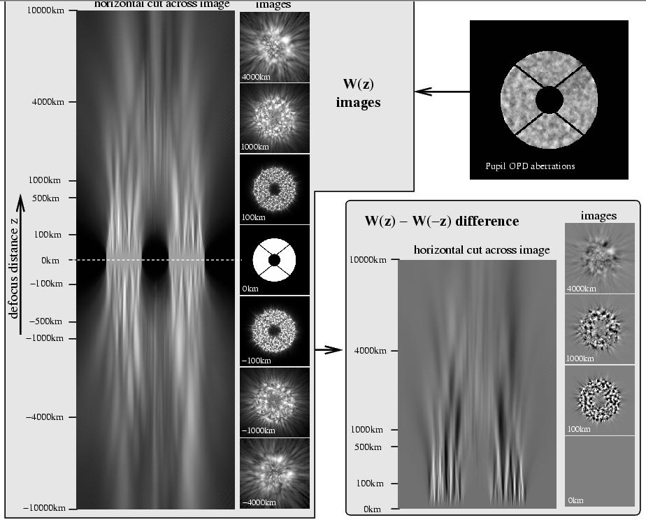
42 Linear Curvature WFS also suffers from the same poor sensitivity for low order aberrations Uses light propagation to convert phase into intensity -> measure intensity in at least 2 defocused pupil planes and compute phase. Usually, planes at +dz and dz, with dz ~ 1000km are imaged. If dz small (~1000 km), defocused images are linear function of wavefront curvature Next slide shows how phase is converted into intensity modulation in a CWFS
43

44 Problem #1: The Linear domain of curvature wavefront sensing (= defocus range within which wavefront curvature is linearly transformed into intensity modulation) becomes smaller as the # of actuators increases. -> defocus distance must be kept small -> this forces low spatial frequencies to be poorly sensed on a high order system Low order system High order system Note: This simulation does not telescope include central obstruction

45 Problem #2: Low order aberrations scramble high spatial frequencies -> defocus distance must be kept small
46 Why do SH, Curvature (& modulated pyramid) have sub-optimal sensitivity for low order aberrations? Good measurement of low order aberrations requires interferometric combination of distant parts of the pupil FPWFS does it, but - SH chops pupil in little pieces -> no hope! - Curvature has to keep extrapupil distance small (see previous slides) -> same problem Things get worse as # of actuators go up -> This makes a big difference for ELTs Tip-tilt example (also true for other modes): With low coherence WFS, sigma2 ~ 1/D^2 (more photons) Ideally, one should be able to achieve: sigma2 ~ 1/D^4 (more photons + smaller l/d) SH, linear Curvature are widely used because they are linear over a wide range of WF errors
47 How to build a High sensitivity WFS? Three examples Fixed Pyramid WFS: A pyramid is placed in the focal plane. The starlight hits the tip of the pyramid Zernike phase contrast: A small phase shifting mask is placed in the focal plane. Roughly 1/2 of the light goes through, 1/2 goes around. The two halves interfere to give an intensity signal Mach-Zehnder: An interferometer is assembled by splitting the beam in 2 and recombining the two halves. On one of the arms, a spatial filter (pinhole) is placed to create the reference beam which interferes with the wavefront These 3 options are Linear but will fail if there is more than ~ 1 rad of WF error! -> very poor dynamical range 46
48 Wavefront sensors ''sensitivities'' in linear regime with full coherence (Guyon 2005) Square root of # of photons required to reach fixed sensing accuracy plotted here for phase aberrations only, 8m telescope. Tuned for maximum sensitivity at 0.5 from central star. Figure above shows sensitivity (y axis) as a function of pupil spatial frequency (x axis). Pupil spatial frequency = angular separation in focal plane. ALL wavefront sensor options have very good sensitivity at the spatial frequency defined by the WFS sampling SOME wavefront sensors loose sensitivity at low spatial frequencies (red), other do not (blue)
49 sensitivity range Extended target? (LGS) chromaticity maturity detector use SH serious noise propagation Very good Yes Low on sky at least 4 pixels per subaperture Curvature serious noise propagation Very good Somewhat LGS OK Low on sky 1 pix/subaperture 2 reads Pyramid (modulated) noise propagation very good Somewhat LGS OK Low on sky 4 pix/subaperture Pyramid (fixed) Excellent limited to < 1 rad in closed loop No Low closed loop lab AO w turbulence 4 pix/subaperture Zernike phase contrast Excellent limited to < 1 rad in closed loop No mask manufacturing? 1 pix/subaperture Mach-Zehnder Excellent limited to < 1 rad in closed loop No low if near zero OPD? 2 pix/subaperture Focal plane Excellent Good, can have > 1 rad error, but needs coherence No serious closed loop lab AO no turbulence 4 pix/speckle Non-linear curvature Excellent Good, can have > 1 rad error, but needs coherence No Low in lab with no turbulence 48 4 pix/subaperture
50 Can a WFS with good sensitivity and range be built? Yes, but it has to be non-linear Next 3 slides describe one such concept, the non-linear curvature WFS (= phase diversity near pupil plane) 49
51
 ref: Guyon, 2009")
52 Operation of curvature WFS in non-linear regime, with large defocus distances, solves the noise propagation effect. Reconstruction algorithm is similar to phase retrieval (algorithm needs to be fast, with few iterations) ref: Guyon, 2009 (submitted)

53 Closed loop simulated PSFs with ideal AO system 8m telescope, 0.85 micron, 3e6 ph/s SH, D/d = 9 SH, D/d = 18 SH, D/d = nm RMS 195 nm RMS 183 nm RMS SH, D/d = 60 Loop OFF Non-linear Curvature 225 nm RMS 1600 nm RMS 105 nm RMS Note: bow tie is due to wind direction in this simple 1 layer turbulence model 52
54 Can a WFS with good sensitivity and range be built? Yes, but it has to be non-linear Next 4 slides describe another similar concept, the non-linear focal plane WFS (= phase diversity in focal plane) 53
 can be controlled to ''perfectly'' cancel speckles DM can be also be asked to create arbitrary speckle field for WFS Key advantages: - no non-common path errors - high")
55 Malbet, Yu & Shao (1995) Guyon (2005) Give'on ( ) Borde & Traub (2006) Focal plane WFS: a non-linear WFS well suited for Extreme AO If speckle field Complex amplitude is known, DM(s) can be controlled to ''perfectly'' cancel speckles DM can be also be asked to create arbitrary speckle field for WFS Key advantages: - no non-common path errors - high sensitivity
56 How to optimally measure speckle field complex amplitude? Use upstream DM to introduce phase diversity. Conventional phase diversity: focus With DM: freedom to tune the diversity to the problem Measure speckle field with no previous knowledge: - take one frame this gives a noisy measure of the speckle field amplitude, but not phase - compute 2 DM shapes which will add known speckles on top of existing speckles. These 2 additive speckle field have same amplitude as existing speckles, and the phase offset between the 2 additive speckle fields is PI/2 -> for each point in the focal plane, 3 intensities -> single solution for phase & amplitude of speckle field


57 Initial problem Complex amplitude of speckle Take a frame -> measured speckle intensity = I0 sqrt(i0) + sigma0 sqrt(i0) - sigma0 DM offset chosen to be ~ equal to speckle amplitude DM offset DM offset 1

58 Lab results with PIAA coronagraph + FPAO with 32x32 MEMs DM See also results obtained at JPL HCIT & Princeton lab
59 sensitivity range Extended target? (LGS) chromaticity maturity detector use SH serious noise propagation Very good Yes Low on sky at least 4 pixels per subaperture Curvature serious noise propagation Very good Good range/linearity but Somewhat poor sensitivity LGS OK Low on sky 1 pix/subaperture 2 reads Pyramid (modulated) noise propagation very good Somewhat LGS OK Low on sky 4 pix/subaperture Pyramid (fixed) Excellent limited to < 1 rad in closed loop No Low closed loop lab AO w turbulence 4 pix/subaperture Zernike phase contrast Excellent limited to < 1 rad in closed loop Good No sensitivity mask over a small range manufacturing? 1 pix/subaperture Mach-Zehnder Excellent limited to < 1 rad in closed loop No low if near zero OPD? 2 pix/subaperture Focal plane Excellent Good, can have > 1 rad error, but needs coherence Non-linear curvature Excellent Good, can have > 1 rad error, but needs coherence No serious closed loop lab AO no turbulence 4 pix/speckle Non-linear reconstruction algorithm allows good No sensitivity Lowand larger in lab range, with no but 4 pix/subaperture requires 58 high coherence turbulence
60 WFS range & linearity: why can t we get both simultaneously? small x: phi < 1 rad WFS signal is linear with phase aberrations small x large x large x: phi > 1 rad WFS signal is non-linear with phase aberrations WFS range, linearity and WFS sensitivity are pushing the WFS architecture in opposite directions Solution: Non-linear reconstruction allows a large dynamical range measurement on a high-sensitivity WFS
61 Guide star for WFS: COHERENCE COHERENCE = ability to make coherent interferences between different parts of the pupil For a high sensitivity WFS to work, coherence MUST be high across large parts of the pupil Coherence is usually high across small parts of the pupil, low across large parts of the pupil What makes the guide star incoherent? Wavefront stability during sampling time sampling time too long / turbulence too fast sensing wavelength too short vibrations Large time-variable and/or unknown wavefront errors poor correction open loop wavefront sensing Angular size of source Atmospheric dispersion source resolved > lambda/d Chromaticity
62 Temporal coherence: long WFS exposure will greatly attenuate the signal Limits the WFS sensitivity in low light level, where long WFS exposure is required Spatial coherence: Sensitivity will not be achieved on extended targets Extended target = points separated by large distance in the pupil plane will produce weak interference This is fundamentally same thing as saying that TT on an extended target is less sensitive Fundamental effect, will limit all WFS designs equally Chromatic coherence: WFS design must work in broadband Problem for focal plane WFS, other WFS concepts can work in broadband 61
63 interferometer representation of temporal coherence in WFS High coherence Low coherence phase Complex amplitude vectors Interferometric signal used to measure phase
64 sensitivity range Extended target? (LGS) chromaticity maturity detector use SH serious noise propagation Very good Yes Low on sky at least 4 pixels per subaperture Curvature serious noise propagation Very good Somewhat LGS OK Low on sky 1 pix/subaperture 2 reads Pyramid (modulated) noise propagation very good Somewhat LGS OK Low on sky 4 pix/subaperture Pyramid (fixed) Excellent limited to < 1 rad in closed loop No Low closed loop lab AO w turbulence 4 pix/subaperture Zernike phase contrast Excellent limited to < 1 rad in closed loop No mask manufacturing? 1 pix/subaperture Mach-Zehnder Excellent limited to < 1 rad in closed loop No low if near zero OPD? 2 pix/subaperture Focal plane Excellent Good, can have > 1 rad error, but needs coherence No serious closed loop lab AO no turbulence 4 pix/speckle Non-linear curvature Excellent Good, can have > 1 rad error, but needs coherence No Low in lab with no turbulence 63 4 pix/subaperture
65 Matching: Wavefront COHERENCE in WFS to Wavefront sensor << 1 rad Space Extreme-AO (Terrestrial Planet Finder) Second-stage of Extreme-AO system in near-ir ( Tweeter ) Interferometric Focal plane ~ 1 rad Extreme-AO Closed loop in Visible Thermal IR AO on 8m telescope open loop Not allowed Pyramid (fixed) general purpose AO system in closed loop allowed Pyramid (modulated) >> 1 rad LGS AO GLAO Open loop AO Curvature Shack-Hartmann
66 sensitivity range Extended target? (LGS) chromaticity maturity detector use SH serious noise propagation Very good Yes Low on sky at least 4 pixels per subaperture Curvature serious noise propagation Very good Somewhat LGS OK Low on sky 1 pix/subaperture 2 reads Pyramid (modulated) noise propagation very good Somewhat LGS OK Low on sky 4 pix/subaperture Pyramid (fixed) Excellent limited to < 1 rad in closed loop No Low closed loop lab AO w turbulence 4 pix/subaperture Zernike phase contrast Excellent limited to < 1 rad in closed loop No mask manufacturing? 1 pix/subaperture Mach-Zehnder Excellent limited to < 1 rad in closed loop No low if near zero OPD? 2 pix/subaperture Focal plane Excellent Good, can have > 1 rad error, but needs coherence No serious closed loop lab AO no turbulence 4 pix/speckle Non-linear curvature Excellent Good, can have > 1 rad error, but needs coherence No Low in lab with no turbulence 65 4 pix/subaperture
67 How to choose the best WFS(s)? A few guidelines... WFS for LGS should be SH, Curv (or modulated pyramid?) For NGS AO, a multi-stage approach is attractive to combine advantages of several WFS options this is especially attractive for Extreme-AO systems, for which the highest sensitivity WFS options would increase science return, but may not be able to close the loop if used alone 66
68 Example: Possible Coronagraphic ExAO architecture AO with visible WFS (Curvature or Shack Hartmann) Coronagraph Focal plane AO Near-IR Fast camera for focal plane WFS AO with high sensitivity after coronagraph WFS in visible (examples: Pyramid, interferometer, focal plane WFS) Science frame acquired by the same camera as FPWFS -The first step is used to clean the wavefront within ~ 1 rad in Visible -The second step operates in the high coherence regime, and adopts a high sensitivity WFS. -Last step uses focal plane WFS free of non-common path errors (Gemini Planet Imager (GPI) uses a similar strategy, with an interferometer WFS to measure coherent residuals)
69 Outline Astronomical AO system diversity Main challenges / error budget terms in astronomical AO systems Wavefront sensing strategy Optical/mechanical design considerations From photons to DM commands: making it all work nicely together
 AO system then needs to be compatible with chopping (this is not")
70 Thermal IR instruments need low thermal background -> fewer warm optics adaptive secondary mirror (MMT, LBT) Thermal IR instruments may need chopping (on source / off source images to calibrate background) AO system then needs to be compatible with chopping (this is not easy)
71 The required field of view & field format drives the AO system optical design (& more) Example 1: System offering wide FOV over full continuous field -> large optics, several large Deformable Mirrors (MCAO) -> AO system works in closed loop, with several WFSs and several DMs -> Multiple guide stars needed, with required positioning devices (NGS) or several laser beacons. Example 2: Several small individual FOVs spread over a large field -> The instrument could have small independent wavefront correction units (1 per small field) to minimize optical size/complexity -> These small units should be fed by a smaller number of WFSs using tomographic reconstruction. -> The WFSs would be running in open loop, and do not see the correction by the DMs. -> The DMs would therefore need to be very well calibrated 70
72 Communication between telescope/ instruments and AO system On modern telescopes, the AO system can offload wavefront aberrations to primary mirror, tip/tilt/focus secondary mirror and telescope pointing. The AO system drives the telescope. Facility AO systems can feed several instruments, and can be a layer which processes the beam prior to sending it to instruments. 71


73 The next generation of large telescopes combine AO with telescope design The 42m diameter European Extremely Large Telescope (EELT) optical design includes DMs as large fold mirrors (2.5m and 2.7m diameter). 72
 secondary")

74 The Giant Magellan Telescope (GMT) secondary mirrors are adaptive and serve as DMs for the AO system(s). 73
,")


75 The Thirty Meter Telescope (TMT), just like GMT and ELT, includes adaptive optics for first generation instruments. 74
76 Outline Astronomical AO system diversity Main challenges / error budget terms in astronomical AO systems Wavefront sensing strategy Optical/mechanical design considerations From photons to DM commands: making it all work nicely together
77 AO control How should the AO system drive the DM from WFS measurements? standard solution (fast, linear): - Measure/model how WFS measures DM commands - If relationship is linear, this is stored as a response matrix response matrix is inverted -> control matrix (this step usually includes some filtering see next slide) - WFS measurements x control matrix = DM commands This could also be done by computing explicitly the wavefront: WFS measurements -> wavefront -> DM commands Good AO control now allows to separate WFS choice from DM choice: example: Curvature WFS could run with a MEMs DM
78 AO control Modal control/filtering helps a lot Concept: Run AO loop at different speed for each mode, depending upon mode strength & WFS sensitivity for the mode - reject bad modes which can be produced by DM but not well sensed by WFS - attenuate known vibrations - powerful tool for system diagnostic Example: mode poorly seen (noisy) by WFS & weak in the atmosphere should be prevented from feeding strong signals to DM powerful & well sensed mode should be rapidly driving the DM Modal control continuously tunes the system for optimal perf.
79 Realistic simulation of AO system is extremely useful AO simulations are relatively accurate, as input and outputs are well known: - seeing properties are fairly well known (Kolmogorov layers) - WFS behavior & properties are usually very well known - Control algorithm identical in simulations & on the sky AO simulations can investigate: -> performance vs. # of actuators, DM type/geometry -> loop instabilities & mode filtering -> hardware trade-off: WFS detector readout noise DM hysteresis speed of electronics & computer Laser power for LGS On-axis vs. off-axis LGS -> alignment tolerance
80 Telemetry is also very important Recording WFS and DM data allows: - seeing estimation & logging - self-tuning of system - diagnostics If a strange behaviour is observed in the AO loop, it is very hard to identify it without being able to play back the time when it occurs. Issues: Disk space File management, archiving
81 Top 10 things NOT TO DO in astronomical adaptive optics (10) Build a 5000 actuator system stuck at ~100Hz because of limited computer power or hardware (9) Build a LGS system (I really think lasers are cool) with a fixed pyramid wavefront sensor (I heard it s the best) for Extreme-AO on bright stars (seeing planets is cool!) (8) Build a 5000 actuator SH NGS system for general astrophysics imaging (7) Put a high order SH system in space for exoplanet imaging (6) Start right now a 10 yr long very expensive project using brand new technology (5) Forget about non-common path errors in an Extreme-AO system (4) Forget about telescope vibration (wind, pumps) (3) Mount a strong massive tip-tilt mount on a small flexible optical bench (2) I have problems with turbulence on my AO bench -> I ll mount big fans on an ExAO system bench for cooling components (cameras, motors) (1) Build an AO system that can keep the loop closed to very high performance, but can t close the loop 80
Adaptive Optics for the Giant Magellan Telescope. Marcos van Dam Flat Wavefronts, Christchurch, New Zealand
 Adaptive Optics for the Giant Magellan Telescope Marcos van Dam Flat Wavefronts, Christchurch, New Zealand How big is your telescope? 15-cm refractor at Townsend Observatory. Talk outline Introduction
An Introduction to. Adaptive Optics. Presented by. Julian C. Christou Gemini Observatory
 An Introduction to Adaptive Optics Presented by Julian C. Christou Gemini Observatory Gemini North in action Turbulence An AO Outline Atmospheric turbulence distorts plane wave from distant object. How
Error Budgets, and Introduction to Class Projects. Lecture 6, ASTR 289
 Error Budgets, and Introduction to Class Projects Lecture 6, ASTR 89 Claire Max UC Santa Cruz January 8, 016 Page 1 What is residual wavefront error? Telescope AO System Science Instrument Very distorted
Lecture 15 The applications of tomography: LTAO, MCAO, MOAO, GLAO
 Lecture 15 The applications of tomography: LTAO, MCAO, MOAO, GLAO Claire Max AY 289 March 3, 2016 Page 1 Outline of lecture What is AO tomography? Applications of AO tomography Laser tomography AO Multi-conjugate
Exoplanet Instrumentation with an ASM
 Exoplanet Instrumentation with an ASM Olivier Guyon1,2,3,4, Thayne Currie 1 (1) Subaru Telescope, National Astronomical Observatory of Japan (2) National Institutes for Natural Sciences (NINS) Astrobiology
Exoplanet High Contrast Imaging Technologies Ground
 Exoplanet High Contrast Imaging Technologies Ground KISS Short Course: The Hows and Whys of Exoplanet Imaging Jared Males University of Arizona Telescope Diameter (Bigger is Better) Diameter: Collecting
Astronomie et astrophysique pour physiciens CUSO 2015
 Astronomie et astrophysique pour physiciens CUSO 2015 Instruments and observational techniques Adaptive Optics F. Pepe Observatoire de l Université Genève F. Courbin and P. Jablonka, EPFL Page 1 Adaptive
1. INTRODUCTION ABSTRACT
 Simulations of E-ELT telescope effects on AO system performance Miska Le Louarn* a, Pierre-Yves Madec a, Enrico Marchetti a, Henri Bonnet a, Michael Esselborn a a ESO, Karl Schwarzschild strasse 2, 85748,
Speckles and adaptive optics
 Chapter 9 Speckles and adaptive optics A better understanding of the atmospheric seeing and the properties of speckles is important for finding techniques to reduce the disturbing effects or to correct
Sky Projected Shack-Hartmann Laser Guide Star
 Sky Projected Shack-Hartmann Laser Guide Star T. Butterley a, D.F. Buscher b, G. D. Love a, T.J. Morris a, R. M. Myers a and R. W. Wilson a a University of Durham, Dept. of Physics, Rochester Building,
A novel laser guide star: Projected Pupil Plane Pattern
 A novel laser guide star: Projected Pupil Plane Pattern Huizhe Yang a, Nazim Barmal a, Richard Myers a, David F. Buscher b, Aglae Kellerer c, Tim Morris a, and Alastair Basden a a Department of Physics,
NA LASER GUIDE STAR AO WITH DYNAMICAL REFOCUS
 Florence, Italy. Adaptive May 2013 Optics for Extremely Large Telescopes III ISBN: 978-88-908876-0-4 DOI: 10.12839/AO4ELT3.13893 NA LASER GUIDE STAR AO WITH DYNAMICAL REFOCUS Sebastian Rabien 1,a, Fernando
Control of the Keck and CELT Telescopes. Douglas G. MacMartin Control & Dynamical Systems California Institute of Technology
 Control of the Keck and CELT Telescopes Douglas G. MacMartin Control & Dynamical Systems California Institute of Technology Telescope Control Problems Light from star Primary mirror active control system
Telescopes & Adaptive Optics. Roberto Ragazzoni INAF Astronomical Observatory of Padova
 Telescopes & Adaptive Optics Roberto Ragazzoni INAF Astronomical Observatory of Padova PAST PAST FUTURE This is a simmetry line This object is drawn in a plane but it acctually reppresent a three dimensional
Direct imaging and characterization of habitable planets with Colossus
 Direct imaging and characterization of habitable planets with Colossus Olivier Guyon Subaru Telescope, National Astronomical Observatory of Japan University of Arizona Contact: guyon@naoj.org 1 Large telescopes
Phase-Referencing and the Atmosphere
 Phase-Referencing and the Atmosphere Francoise Delplancke Outline: Basic principle of phase-referencing Atmospheric / astrophysical limitations Phase-referencing requirements: Practical problems: dispersion
Adaptive Optics Overview Phil Hinz What (Good) is Adaptive Optics?
 is Adaptive Optics?") Adaptive Optics Overview Phil Hinz (phinz@as.arizona.edu) What (Good) is Adaptive Optics? System Overview MMT AO system Atmospheric Turbulence Image Structure References: Adaptive Optics for Astronomical
Adaptive Optics Overview Phil Hinz (phinz@as.arizona.edu) What (Good) is Adaptive Optics? System Overview MMT AO system Atmospheric Turbulence Image Structure References: Adaptive Optics for Astronomical
End-to-end model for the Polychromatic Laser Guide Star project (ELP-OA)
") 1st AO4ELT conference, 04006 (2010) DOI:10.1051/ao4elt/201004006 Owned by the authors, published by EDP Sciences, 2010 End-to-end model for the Polychromatic Laser Guide Star project (ELP-OA) N. Meilard
1st AO4ELT conference, 04006 (2010) DOI:10.1051/ao4elt/201004006 Owned by the authors, published by EDP Sciences, 2010 End-to-end model for the Polychromatic Laser Guide Star project (ELP-OA) N. Meilard
Wavefront errors due to atmospheric turbulence Claire Max
 Wavefront errors due to atmospheric turbulence Claire Max Page 1 Kolmogorov turbulence, cartoon solar Outer scale L 0 Inner scale l 0 h Wind shear convection h ground Page Atmospheric Turbulence generally
NB: from now on we concentrate on seeing, as scintillation for large telescopes is unimportant
 b) intensity changes: scintillation!i/i on the ground is proportional to h!", i.e. # h e -h/h this function has maximum at h = H = 8.5 km! scintillation comes mostly from high layers! seeing and scintillation
Analysis of the Sequence Of Phase Correction in Multiconjugate Adaptive Optics
 Analysis of the Sequence Of Phase Correction in Multiconjugate Adaptive Optics Luzma Montoya, Iciar Montilla Instituto de Astrofísica de Canarias Edinburgh, 25-26/03/2014 AO Tomography Workshop The EST
THE SUBARU CORONAGRAPHIC EXTREME AO HIGH SENSITIVITY VISIBLE WAVEFRONT SENSORS
 Florence, Italy. May 2013 ISBN: 978-88-908876-0-4 DOI: 10.12839/AO4ELT3.13398 THE SUBARU CORONAGRAPHIC EXTREME AO HIGH SENSITIVITY VISIBLE WAVEFRONT SENSORS Christophe Clergeon 1a, Olivier Guyon 1, Frantz
The MAORY Multi-Conjugate Adaptive Optics module Emiliano Diolaiti Istituto Nazionale di Astrofisica
 The MAORY Multi-Conjugate Adaptive Optics module Emiliano Diolaiti Istituto Nazionale di Astrofisica On behalf of the MAORY module Consortium Shaping E-ELT Science and Instrumentation workshop, ESO, 25
Medium baseline, high sensitivity, high efficiency imaging interferometer for general astrophysics
 Compact Fizeau Array as an ELT alternative Medium baseline, high sensitivity, high efficiency imaging interferometer for general astrophysics Olivier Guyon (Subaru Telescope) with inputs from: R. Angel,
High Contrast Imaging: New Techniques and Scientific Perspectives for ELTs
 High Contrast Imaging: New Techniques and Scientific Perspectives for ELTs Is there a path to life What game changing finding with ELTs? technologies can get us there? Olivier Guyon Subaru Telescope &
Introduction to Adaptive Optics. Tim Morris
 Introduction to Adaptive Optics Tim Morris Contents Definitions and introduction Atmospheric turbulence Components of an AO system Wavefront Sensing Wavefront Correction Turbulence Conjugation Laser Beacons
Telescope Project Development Seminar
 Telescope Project Development Seminar Session 5a: Science Instruments & Adaptive Optics Session 5b: Lessons Learned & Discussion Matt Johns 4/27/2017 U. Tokyo 4/27/2017 Telescope Project Development 1
Point spread function reconstruction at W.M. Keck Observatory : progress and beyond
 Point spread function reconstruction at W.M. Keck Observatory : progress and beyond Olivier Beltramo-Martin Aix-Marseille Univ., LAM, A*MIDEX, Extra November 9th, 217 - LAM Olivier Beltramo-Martin (LAM)
Sky demonstration of potential for ground layer adaptive optics correction
 Sky demonstration of potential for ground layer adaptive optics correction Christoph J. Baranec, Michael Lloyd-Hart, Johanan L. Codona, N. Mark Milton Center for Astronomical Adaptive Optics, Steward Observatory,
Ground-Layer Adaptive Optics Christoph Baranec (IfA, U. Hawai`i)
") Ground-Layer Adaptive Optics Christoph Baranec (IfA, U. Hawai`i) Photo credit: T. Stalcup What is Ground-layer Adaptive Optics (GLAO)? Benefits of GLAO to astronomy. MMT multiple-laser AO system. Ground-layer
Ground-Layer Adaptive Optics Christoph Baranec (IfA, U. Hawai`i) Photo credit: T. Stalcup What is Ground-layer Adaptive Optics (GLAO)? Benefits of GLAO to astronomy. MMT multiple-laser AO system. Ground-layer
Laboratory Experiments of Laser Tomographic Adaptive Optics at Visible Wavelengths on a 10-meter Telescope
 1st AO4ELT conference, 08005 (2010) DOI:10.1051/ao4elt/201008005 Owned by the authors, published by EDP Sciences, 2010 Laboratory Experiments of Laser Tomographic Adaptive Optics at Visible Wavelengths
Modelling the multi-conjugate adaptive optics system of the European Extremely Large Telescope
 Mem. S.A.It. Vol. 86, 436 c SAIt 2015 Memorie della Modelling the multi-conjugate adaptive optics system of the European Extremely Large Telescope L. Schreiber 1, C. Arcidiacono 1, G. Bregoli 1, E. Diolaiti
Field Tests of elongated Sodium LGS wave-front sensing for the E-ELT
 Florence, Italy. May 2013 ISBN: 978-88-908876-0-4 DOI: 10.12839/AO4ELT3.13437 Field Tests of elongated Sodium LGS wave-front sensing for the E-ELT Gérard Rousset 1a, Damien Gratadour 1, TIm J. Morris 2,
Astronomical Observing Techniques Lecture 13: Adap<ve Op<cs
 Astronomical Observing Techniques Lecture 13: Adap
Wavefront Sensing using Polarization Shearing Interferometer. A report on the work done for my Ph.D. J.P.Lancelot
 Wavefront Sensing using Polarization Shearing Interferometer A report on the work done for my Ph.D J.P.Lancelot CONTENTS 1. Introduction 2. Imaging Through Atmospheric turbulence 2.1 The statistics of
Astronomical Observing Techniques 2017 Lecture 13: Twinkle, twinkle star... No more!
 Astronomical Observing Techniques 2017 Lecture 13: Twinkle, twinkle li@le star... No more! Christoph U. Keller keller@strw.leidenuniv.nl Overview 1. The Power of Adaptive Optics 2. Atmospheric Turbulence
ADVANCEMENT OF AO TECHNOLOGY FOR THE NEXT GENERATION OF EXTREMELY LARGE TELESCOPES
 ADVANCEMENT OF AO TECHNOLOGY FOR THE NEXT GENERATION OF EXTREMELY LARGE TELESCOPES Donald Gavel 1 University of California Observatories, UC Santa Cruz, 1156 High Street, Santa Cruz, CA, USA 95064 Abstract.
Giant Magellan Telescope
 Giant Magellan Telescope Faint Object Adap6ve Op6cs Michael Hart Steward Observatory, The University of Arizona Challenges for the GMT Melbourne, June 16, 2010 Importance of AO The ELTs in general, including
Exoplanets Direct imaging. Direct method of exoplanet detection. Direct imaging: observational challenges
 Black body flux (in units 10-26 W m -2 Hz -1 ) of some Solar System bodies as seen from 10 pc. A putative hot Jupiter is also shown. The planets have two peaks in their spectra. The short-wavelength peak
ADVANCING HIGH-CONTRAST ADAPTIVE OPTICS
 ADVANCING HIGH-CONTRAST ADAPTIVE OPTICS S. Mark Ammons LLNL Bruce Macintosh Stanford University Lisa Poyneer LLNL Dave Palmer LLNL and the Gemini Planet Imager Team ABSTRACT A long-standing challenge has
Exoplanets Direct imaging. Direct method of exoplanet detection. Direct imaging: observational challenges
 Black body flux (in units 10-26 W m -2 Hz -1 ) of some Solar System bodies as seen from 10 pc. A putative hot Jupiter is also shown. The planets have two peaks in their spectra. The short-wavelength peak
Atmospheric Turbulence and its Influence on Adaptive Optics. Mike Campbell 23rd March 2009
 Atmospheric Turbulence and its Influence on Adaptive Optics Mike Campbell 23rd March 2009 i Contents 1 Introduction 1 2 Atmospheric Turbulence 1 Seeing..................................................
The Potential of Ground Based Telescopes. Jerry Nelson UC Santa Cruz 5 April 2002
 The Potential of Ground Based Telescopes Jerry Nelson UC Santa Cruz 5 April 2002 Contents Present and Future Telescopes Looking through the atmosphere Adaptive optics Extragalactic astronomy Planet searches
Wavefront Sensing in Astronomy
 Wavefront Sensing in Astronomy by INAF Arcetri Observatory (Florence - Italy) ragazzoni@arcetri.astro.it Why WaveFront Sensing in Astronomy? Because most of visible and Near IR Astronomy is still made
Keck Adaptive Optics Note 1069
 Keck Adaptive Optics Note 1069 Tip-Tilt Sensing with Keck I Laser Guide Star Adaptive Optics: Sensor Selection and Performance Predictions DRAFT to be updated as more performance data becomes available
Astronomical Seeing. Northeast Astro-Imaging Conference. Dr. Gaston Baudat Innovations Foresight, LLC. April 7 & 8, Innovations Foresight
 Astronomical Seeing Northeast Astro-Imaging Conference April 7 & 8, 2016 Dr. Gaston Baudat, LLC 1 Seeing Astronomical seeing is the blurring of astronomical objects caused by Earth's atmosphere turbulence
Adaptive Optics Status & Roadmap. Norbert Hubin Adaptive Optics Department European Southern Observatory November 2007
 Adaptive Optics Status & Roadmap Norbert Hubin Adaptive Optics Department European Southern Observatory November 2007 1 Analysis CASIS: VLT MCAO Imager NACO upgrade Commissioning PAC The ESO Adaptive Optics
1. Give short answers to the following questions. a. What limits the size of a corrected field of view in AO?
 Astronomy 418/518 final practice exam 1. Give short answers to the following questions. a. What limits the size of a corrected field of view in AO? b. Describe the visibility vs. baseline for a two element,
MAORY (Multi conjugate Adaptive Optics RelaY) for E-ELT. Paolo Ciliegi. On behalf of the MAORY Consortium
 for E-ELT. Paolo Ciliegi. On behalf of the MAORY Consortium") MAORY (Multi conjugate Adaptive Optics RelaY) for E-ELT Paolo Ciliegi INAF Osservatorio Astronomico di Bologna On behalf of the MAORY Consortium Science ELT Workshop Team Meeting ESO Garching, MPE Garching,
MAORY (Multi conjugate Adaptive Optics RelaY) for E-ELT Paolo Ciliegi INAF Osservatorio Astronomico di Bologna On behalf of the MAORY Consortium Science ELT Workshop Team Meeting ESO Garching, MPE Garching,
What do companies win being a supplier to ESO
 What do companies win being a supplier to ESO Arnout Tromp Head of Contracts and Procurement Topics Characteristics of what ESO procures Technology in Astronomy Spin off from the past The future: E-ELT
EPICS: A planet hunter for the European ELT
 EPICS: A planet hunter for the European ELT M. Kasper, C. Verinaud, J.L. Beuzit, N. Yaitskova, A. Boccaletti, S. Desidera, K. Dohlen, T. Fusco, N. Hubin, A. Glindemann, R. Gratton, N. Thatte 42-m E-ELT
Subaru GLAO Simulation. Shin Oya (Subaru Telescope) Hilo
 Hilo") Subaru GLAO Simulation Shin Oya (Subaru Telescope) 2012/6/4 @ Hilo Background Subaru Telescope LGSAO188: commissioning is finishing optical instruments (dark nights) huge projects for prime focus HSC:
Subaru GLAO Simulation Shin Oya (Subaru Telescope) 2012/6/4 @ Hilo Background Subaru Telescope LGSAO188: commissioning is finishing optical instruments (dark nights) huge projects for prime focus HSC:
Achieving high resolution
 Achieving high resolution Diffraction-limited performance with single telescopes with Adaptive Optics Or sparse aperture masking Use masks to sub-divide telescope primary into a numnber of subapertures
CURRENT STATUS OF RAVEN, A MOAO SCIENCE DEMONSTRATOR FOR SUBARU
 Florence, Italy. May 013 ISBN: 978-88-908876-0-4 DOI: 10.1839/AO4ELT3.15991 CURRENT STATUS OF RAVEN, A MOAO SCIENCE DEMONSTRATOR FOR SUBARU Olivier Lardière 1a, Dave Andersen, Colin Bradley 1,Célia Blain
Application of Precision Deformable Mirrors to Space Astronomy
 Application of Precision Deformable Mirrors to Space Astronomy John Trauger, Dwight Moody Brian Gordon, Yekta Gursel (JPL) Mark Ealey, Roger Bagwell (Xinetics) Workshop on Innovative Designs for the Next
Raven, a Multi-Object Adaptive Optics technology and science demonstrator
 Raven, a Multi-Object Adaptive Optics technology and science demonstrator D.R. Andersen 1,a, C. Bradley 2, O. Lardière 2, C. Blain 2, D. Gamroth 2, M. Ito 2, K. Jackson 2, P. Lach 2, R. Nash 2, L. Pham
Optical interferometry: problems and practice
 Outline Optical interferometry: problems and practice Chris Haniff Aims. What is an interferometer? Fundamental differences between optical and radio. Implementation at optical wavelengths. Conclusions.
Comparison of Adaptive Optics Technologies for Gemini
 Comparison of Adaptive Optics Technologies for Gemini.7.6.5 Strehl.4.3.2.1 Malcolm (APD, 56 act.) Francois (APD, 56 act.) Brent (5 e-, D/d=1) Francois (5 e-, D/d=9) 11 12 13 14 15 16 17 18 19 Brent Ellerbroek
Disturbance Feedforward Control for Vibration Suppression in Adaptive Optics of Large Telescopes
 Disturbance Feedforward Control for Vibration Suppression in Adaptive Optics of Large Telescopes Martin Glück, Jörg-Uwe Pott, Oliver Sawodny Reaching the Diffraction Limit of Large Telescopes using Adaptive
High contrast imaging at 3-5 microns. Philip M. Hinz University of Arizona Matt Kenworthy, Ari Heinze, John Codona, Roger Angel
 High contrast imaging at 3-5 microns Philip M. Hinz University of Arizona Matt Kenworthy, Ari Heinze, John Codona, Roger Angel University of Arizona ABSTRACT The 6.5 m MMT with its integrated deformable
Wavefront reconstruction for adaptive optics. Marcos van Dam and Richard Clare W.M. Keck Observatory
 Wavefront reconstruction for adaptive optics Marcos van Dam and Richard Clare W.M. Keck Observatory Friendly people We borrowed slides from the following people: Lisa Poyneer Luc Gilles Curt Vogel Corinne
Measuring Segment Piston with a Non-Redundant Pupil Mask on the Giant Magellan Telescope
 Measuring Segment Piston with a Non-Redundant Pupil Mask on the Giant Magellan Telescope Marcos A. van Dam, a Peter G. Tuthill b, Anthony C. Cheetham, b,c and Fernando Quiros-Pacheco d a Flat Wavefronts,
Christian Marois Lawrence Livermore National Laboratory
 Christian Marois Lawrence Livermore National Laboratory -Detecting Exoplanets -Speckle noise attenuation techniques with specialized observation schemes and post-processing algorithms -Current On-sky performances
Atmospheric dispersion correction for the Subaru AO system
 Atmospheric dispersion correction for the Subaru AO system Sebastian Egner a, Yuji Ikeda b, Makoto Watanabe c,y.hayano a,t.golota a, M. Hattori a,m.ito a,y.minowa a,s.oya a,y.saito a,h.takami a,m.iye d
International Journal of Scientific & Engineering Research, Volume 4, Issue 7, July ISSN
 International Journal of Scientific & Engineering Research, Volume 4, Issue 7, July-2013 96 Performance and Evaluation of Interferometric based Wavefront Sensors M.Mohamed Ismail1, M.Mohamed Sathik2 Research
Pupil mapping Exoplanet Coronagraph Observer (PECO)
") Pupil mapping Exoplanet Coronagraph Observer (PECO) Olivier Guyon University of Arizona Subaru Telescope Thomas Greene (NASA Ames), Marie Levine (NASA JPL), Domenick Tenerelli (Lockheed Martin), Stuart
Pupil mapping Exoplanet Coronagraph Observer (PECO) Olivier Guyon University of Arizona Subaru Telescope Thomas Greene (NASA Ames), Marie Levine (NASA JPL), Domenick Tenerelli (Lockheed Martin), Stuart
arxiv: v1 [astro-ph.im] 12 Jul 2018
![arxiv: v1 [astro-ph.im] 12 Jul 2018](/thumbs/82/85462251.jpg "arxiv: v1 [astro-ph.im] 12 Jul 2018") Shack-Hartmann wavefront sensor sensitivity loss factor estimation in partial correction regime G. Agapito a, C. Arcidiacono b, S. Esposito a a Osservatorio Astrofisico di Arcetri, INAF; b Osservatorio
Shack-Hartmann wavefront sensor sensitivity loss factor estimation in partial correction regime G. Agapito a, C. Arcidiacono b, S. Esposito a a Osservatorio Astrofisico di Arcetri, INAF; b Osservatorio
Development of Field of View for Ground-based Optical Telescopes in Adaptive Optics Xiaochun Zhong 1, 2, a, Shujuan Wang 2, b, Zhiliang Huang 3, c
 3rd International Conference on Mechanical Engineering and Intelligent Systems (ICMEIS 2015) Development of Field of View for Ground-based Optical Telescopes in Adaptive Optics Xiaochun Zhong 1, 2, a,
Presented by B. Neichel. Wide-Field Adaptive Optics for ground based telescopes: First science results and new challenges
 Edinburgh 25 th March 2013 Presented by B. Neichel Wide-Field Adaptive Optics for ground based telescopes: First science results and new challenges Outline A brief Introduction to Adaptive Optics (AO)
Shack-Hartmann wavefront sensor sensitivity loss factor estimation in partial correction regime
 Shack-Hartmann wavefront sensor sensitivity loss factor estimation in partial correction regime Guido Agapito a,c, Carmelo Arcidiacono b,c, and Simone Esposito a,c a INAF Osservatorio Astrofisico di Arcetri,
arxiv: v2 [astro-ph.im] 15 Mar 2016
![arxiv: v2 [astro-ph.im] 15 Mar 2016](/thumbs/81/83249761.jpg "arxiv: v2 [astro-ph.im] 15 Mar 2016") Preprint 14 May 2018 Compiled using MNRAS LATEX style file v3.0 A tomographic algorithm to determine tip-tilt information from laser guide stars A. P. Reeves, 1 T. J. Morris, 1 R. M. Myers, 1 N. A. Bharmal
Preprint 14 May 2018 Compiled using MNRAS LATEX style file v3.0 A tomographic algorithm to determine tip-tilt information from laser guide stars A. P. Reeves, 1 T. J. Morris, 1 R. M. Myers, 1 N. A. Bharmal
The High Order Test Bench: Evaluating High Contrast Imaging Concepts for SPHERE and EPICS
 Telescopes and Instrumentation The High Order Test Bench: Evaluating High Contrast Imaging Concepts for SPHERE and EPICS Patrice Martinez 1 Emmanuel Aller-Carpentier 1 Markus Kasper 1 1 ESO The High Order
MAORY design trade-off study: tomography dimensioning
 MAORY design trade-off study: tomography dimensioning Sylvain Oberti, Miska Le Louarn ESO Garching Emiliano Diolaiti, Carmelo Arcidiacono, Laura Schreiber, Matteo Lombini INAF Bologna and the rest of the
Tomography for Raven, a Multi-Object Adaptive Optics Science and Technology Demonstrator. Kate Jackson. Carlos Correia
 Tomography for Raven, a Multi-Object Adaptive Optics Science and Technology Demonstrator Kate Jackson a Department of Mechanical Engineering, University of Victoria, Victoria, BC V8P 5CS Carlos Correia
The AO and MCAO for the 4m European Solar Telescope
 The AO and MCAO for the 4m European Solar Telescope Thomas Berkefeld a and the EST AO group a Kiepenheuer-Institut für Sonnenphysik, Freiburg, Germany ABSTRACT We give an overview of the Adaptive Optics
Adaptive Optics. Dave Andersen NRC Herzberg.
 Adaptive Optics Dave Andersen NRC Herzberg david.andersen@nrc-cnrc.gc.ca Resources Tokovinin Tutorial: http://www.ctio.noao.edu/~atokovin/tutorial/intro.html - Excellent descriptions of many elements of
Closed Loop Active Optics with and without wavefront sensors
 Closed Loop Active Optics with and without wavefront sensors P. Schipani 1, R. Holzlöhner 2, L. Noethe 2, A. Rakich 2,3, K. Kuijken 4, S. Savarese 1,5, M. Iuzzolino 1,5 1 INAF Osservatorio Astronomico
McMath-Pierce Adaptive Optics Overview. Christoph Keller National Solar Observatory, Tucson
 McMath-Pierce Adaptive Optics Overview Christoph Keller National Solar Observatory, Tucson Small-Scale Structures on the Sun 1 arcsec Important astrophysical scales (pressure scale height in photosphere,
Visible near-diffraction-limited lucky imaging with full-sky laser-assisted adaptive optics
 doi:10.1093/mnras/stu941 Visible near-diffraction-limited lucky imaging with full-sky laser-assisted adaptive optics A. G. Basden Department of Physics, Durham University, South Road, Durham, DH1 3LE,
Laboratory Emulation of Observations from Space
 Science with a Wide-field Infrared Telescopes in Space, Pasadena, Feb 13, 2012 of Observations from Space Roger Smith -- Caltech Jason Rhodes, Suresh Seshadri -- JPL Previous culture, friendly collaboration
Adaptive Optics Lectures
 Adaptive Optics Lectures 1. Atmospheric turbulence Andrei Tokovinin 1 Resources CTIO: www.ctio.noao.edu/~atokovin/tutorial/index.html CFHT AO tutorial: http://www.cfht.hawaii.edu/instruments/imaging/aob/other-aosystems.html
PRELIMINARY PERFORMANCE ANALYSIS OF THE MULTI-CONJUGATE AO SYSTEM OF THE EUROPEAN SOLAR TELESCOPE
 Florence, Italy. May 213 ISBN: 978-88-98876--4 DOI: 1.12839/AO4ELT3.13272 PRELIMINARY PERFORMANCE ANALYSIS OF THE MULTI-CONJUGATE AO SYSTEM OF THE EUROPEAN SOLAR TELESCOPE I. Montilla 1a, C. Béchet 2,3,
The Nulling Coronagraph Using a Nulling Interferometer for Planet Detection in Visible Light with a Single Aperture Telescope
 Terrestrial Planet Finder The Nulling Coronagraph Using a Nulling Interferometer for Planet Detection in Visible Light with a Single Aperture Telescope Michael Shao, B. Martin Levine, Duncan Liu, J. Kent
x Contents Segmented Mirror Telescopes Metal and Lightweight Mirrors Mirror Polishing
 Contents 1 Fundamentals of Optical Telescopes... 1 1.1 A Brief History of Optical Telescopes.................... 1 1.2 General Astronomical Requirements..................... 6 1.2.1 Angular Resolution.............................
Challenges for the next generation stellar interferometer. Markus Schöller European Southern Observatory January 29, 2009
 Challenges for the next generation stellar interferometer Markus Schöller European Southern Observatory January 29, 2009 VLTI Four 8.2m telescopes (UTs) All equipped with AO (MACAO) Six Baselines 47m-130m
Roadmap for PCS, the Planetary Camera and Spectrograph for the E-ELT
 Florence, Italy. Adaptive May 2013 Optics for Extremely Large Telescopes III ISBN: 978-88-908876-0-4 DOI: 10.12839/AO4ELT3.12804 Roadmap for PCS, the Planetary Camera and Spectrograph for the E-ELT Markus
Subaru Next Generation Wide Field AO: Ground Layer AO Simulation
 Subaru Next Generation Wide Field AO: Ground Layer AO Simulation Shin Oya (Subaru Telescope) Subaru Next Generation AO Working Group 2013/5/9 @ Victoria Subaru Next Generation Wide-Field AO multi-laser
Subaru GLAO Simulation. Shin Oya (Subaru Telescope) Hilo
 Hilo") Subaru GLAO Simulation Shin Oya (Subaru Telescope) 2012/10/16 @ Hilo Outline What is Ground Layer Adaptive Optics (GLAO)? a type of wide-field AO Mauna Kea seeing (which determines GLAO performance) Simulation
Subaru GLAO Simulation Shin Oya (Subaru Telescope) 2012/10/16 @ Hilo Outline What is Ground Layer Adaptive Optics (GLAO)? a type of wide-field AO Mauna Kea seeing (which determines GLAO performance) Simulation
Survey of Present and Future Ground-Based Imaging Systems
 Survey of Present and Future Ground-Based Imaging Systems Olivier Guyon (guyon@naoj.org) University of Arizona Subaru Telescope With material from : Rich Dekany, Ben Oppenheimer (Palm 3000, P1640) Bruce
Comparing the performance of open loop centroiding techniques in the Raven MOAO system
 Comparing the performance of open loop centroiding techniques in the Raven MOAO system David R. Andersen *a, Colin Bradley b, Darryl Gamroth b, Dan Kerley a, Olivier Lardière b, Jean-Pierre Véran a a NRC
SPATIO-TEMPORAL PREDICTION FOR ADAPTIVE OPTICS WAVEFRONT RECONSTRUCTORS
 SPATIO-TEMPORAL PREDICTION FOR ADAPTIVE OPTICS WAVEFRONT RECONSTRUCTORS Michael Lloyd-Hart and Patrick McGuire Center for Astronomical Adaptive Optics, Steward Observatory, University of Arizona, Tucson,
University of California Santa Cruz, CA, USA Contents
 University of California Santa Cruz, CA, 95064 USA jnelson@ucolick.org Contents 1. Introduction 1.1. Organization 1.2. Site Selection 1.3. Schedule 1.4. Cost 2. Telescope Overview 3. Key Features of TMT
W.M. Keck Observatory s Next Generation Adaptive Optics Facility
 W.M. Keck Observatory s Next Generation Adaptive Optics Facility P. Wizinowich a, R. Dekany b, D. Gavel c, C. Max c, S. Adkins a, B. Bauman c, J. Bell a, A. Bouchez b, M. Britton b, J. Chin a, R. Flicker
Wide field astronomical image compensation with multiple laser-guided adaptive optics
 Invited Paper Wide field astronomical image compensation with multiple laser-guided adaptive optics Michael Hart, N. Mark Milton, Christoph Baranec, * Thomas Stalcup, Keith Powell, Eduardo Bendek, Don
A down-to-earth guide to high-resolution solar observations. Kevin Reardon National Solar Observatory
 A down-to-earth guide to high-resolution solar observations Kevin Reardon kreardon@nso.edu National Solar Observatory Seeing Adaptive Optics Image Reconstruction Atmospheric Effects Spectral Lines Calibration
Lecture 9: Speckle Interferometry. Full-Aperture Interferometry. Labeyrie Technique. Knox-Thompson Technique. Bispectrum Technique
 Lecture 9: Speckle Interferometry Outline 1 Full-Aperture Interferometry 2 Labeyrie Technique 3 Knox-Thompson Technique 4 Bispectrum Technique 5 Differential Speckle Imaging 6 Phase-Diverse Speckle Imaging
Wide-Field Image Compensation with Multiple Laser Guide Stars
 Wide-Field Image Compensation with Multiple Laser Guide Stars Michael Hart, N. Mark Milton, Keith Powell Center for Astronomical Adaptive Optics, The University of Arizona, Tucson, AZ 85721 Christoph Baranec
The Principles of Astronomical Telescope Design
 The Principles of Astronomical Telescope Design Jingquan Cheng National Radio Astronomy Observatory Charlottesville, Virginia,.USA " 4y Springer Fundamentals of Optical Telescopes 1 1.1 A Brief History
Adaptive Optics Systems for the Thirty Mirror Telescope
 Adaptive Optics Systems for the Thirty Mirror Telescope Brent Ellerbroek,a TMT Observatory Corporation Abstract. At first light, the overall AO system architecture for the Thirty Meter Telescope will consist
High Dynamic Range and the Search for Planets
 Brown Dwarfs IAU Symposium, Vol. 211, 2003 E. L. Martín, ed. High Dynamic Range and the Search for Planets A. T. Tokunaga, C. Ftaclas, J. R. Kuhn, and P. Baudoz Institute for Astronomy, Univ. of Hawaii,