INTRODUCTION TO ENGINEERING SURVEYING (CE 1305)
|
|
|
- Jeffrey Young
- 6 years ago
- Views:
Transcription
 Linear")

1 INTRODUCTION TO ENGINEERING SURVEYING (CE 1305) Linear Measurements Sr Dr. Tan Liat Choon Mobile:


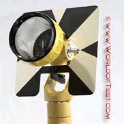
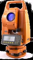

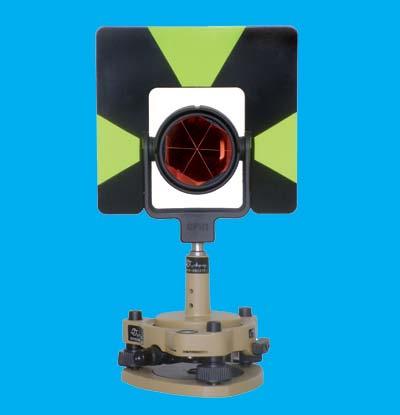
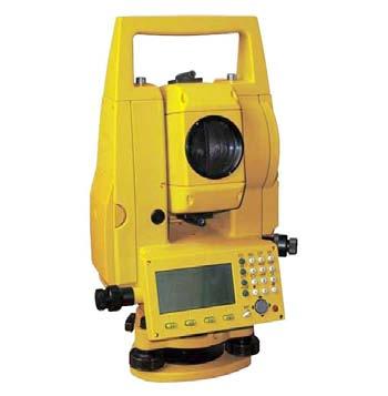
2 EDM, TOTAL STATION, PRISM AND POLE 2
3 ELECTROMAGNETIC DISTANCE MEASUREMENT (EDM) A major advance in surveying instrument occurred approximately 60 years ago with the development of electronic distance measurement (EDM) instruments. These devices measure lengths by indirectly determining the number of full and partial waves of transmitted, electromagnetic energy required in traveling between the two ends of a line. In practice, the energy is transmitted from one end of the line to the other and returned to the starting points 3
4 Definition ELECTROMAGNETIC DISTANCE MEASUREMENT (EDM) The electronic distance measurement instrument (EDM) is a relatively new development in the field of surveying. The instrument sends out a beam of light or high frequency microwaves from one end of line to be measured, and directs it towards the far end of the line. A reflector or transmitter receiver at the far end reflects the light or microwaves back to the instrument where they are analyzed electronically to give the distance between the two points (Francis, 1982) 4

5 ELECTROMAGNETIC DISTANCE MEASUREMENT (EDM) EDM instruments are available to measure distance using light and radio waves. The distance is calculated either from the time difference between a transmitted pulse and a return pulse or the phase difference between a transmitted and a reflected beam of radiation 5
6 ELECTROMAGNETIC DISTANCE Components of EDM MEASUREMENT (EDM) Light source For transferring the electromagnetic waves Light Modulation Change the light to Electromagnetic waves Phase Difference system Mini PC or Calculator 6

7 ELECTROMAGNETIC DISTANCE MEASUREMENT (EDM) Electromagnetic distance measuring equipment use three different wavelength bands: Microwave systems Range up to 150 km Wavelength 3 cm Unaffected by visibility Light wave systems Range up to 5 km Visible light, lasers 3-distance reduced by visibility Infra red systems 1-Range up to 3 km 2-limited to line of sight 3-limited by rain, fog, and other airborne particles EDM and electronic theodolite The accuracy of the measurement varies from type to type but is usually in the range from ±(1.0 mm ppm) to ±(10.0 mm + 5 ppm). EDM and electronic theodolite 7
8 ELECTROMAGNETIC DISTANCE MEASUREMENT (EDM) 8


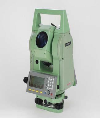
9 TOTAL STATION A Total Station integrates the functions of a theodolite for measuring angles, an EDM for measuring distances, digital data and information recording. Examples of Total Stations are the Nikon DTM 801, Topcon and Geodimeter 400 series Examples of usage General purpose angle and distance measurements. Provision of control surveys, Contour and detail mapping, setting out and construction work Factors which influence the use of Total Stations A clear line of sight between the instrument and the measured points is essential A well defined measurement point or target/prism is required to obtain the maximum accuracy 9

10 TOTAL STATION 10
11 TOTAL STATION INSTRUMENT An electronic digital theodolite and an electronic distance measurement in one integral unit They can automatically record horizontal and vertical angles and slope distances from a single setup Slope distance can be reduced to horizontal and vertical components instantaneously Given initial data they will display positions and elevations of sighted points 11
12 THREE BASIC COMPONENTS Total station instruments combine three basic components into one integral unit An electronic distance measurement (EDM) instrument An electronic angle measurement component A computer or microprocessor 12
13 Vertical axis Handle Collimator Objective lens Vertical circle lock Vertical tangent screw Circular level vial Horizontal circle lock Horizontal circle tangent screw Base Vertical circle Horizontal axis Optical plummet lens focus Optical plummet eyepiece Eyepiece focus Display & Keyboard Tribrach lock Tribrach Tribrach levelling screws 13
14 FEATURES Automatically observe Horizontal and vertical angles Slope distances from a single set up Instantaneously compute Horizontal and vertical distance components Elevations Coordinates of the point sighted Display the result on liquid crystal display (LCD) Store the data, either on board or in external data collectors connected to their communication ports 14
15 FEATURES The EDM instruments that are integrated into the total station instruments, lengths up to about 4km which is adequate for most job Total station instruments are manufactured with two graduated circles, mounted in mutually perpendicular planes Its horizontal circle is oriented in a horizontal plane, which automatically puts the vertical circle in a vertical plane Horizontal and vertical angles can then be measured directly in their respective planes Averaging of multiple angles and distance measurements Correcting electronically measured distances for prism constants, atmospheric pressure and temperature 15
16 TURNING ANGLES WITH TOTAL STATION Sight on the backsight utilizing the horizontal adjustment screw Zero set the instrument (this provides an initial reading of 0 seconds) Loosen tangent screw and rotate instrument to foresight Tighten tangent screw and bring cross hair exact on target with adjustment screw Read and record angle as displayed To close the horizon: Sight on foresight point from above and zero set instrument Rotate to former backsight and adjust instrument to exact Read and record angle as displayed Angle from direct and indirect should equal 360 degrees 16
17 TOTAL STATION DISTANCE MEASUREMENT Point the instrument at a prism (which is vertical over the point) Push the measure button and record the distance You can measure the horizontal distance or the slope distance, it is important that you note which is being collected If you are measuring the slope distance, the zenith angle must be recorded to allow the horizontal distance to be computed If you are collecting topographic data with elevations, it is important that the height of the instrument and the height of the prism be collected and recorded This can also be solved by setting the prism height the same as the instrument height 17
18 TOTAL STATION RULES When moving between setups in the field, proper care should be taken Before the total station is removed from the tripod, the food screw should be returned to the midpoints of the posts The instrument should never be transported on the tripod With adjustable leg tripods, stress on the legs can be avoided by retracting them to their shortest positions and lightly clamping them in position When returning the total station to its case, all locking mechanisms should be released If the instrument is wet, it should be wiped down and left in an open case it is dry 18
19 TOTAL STATION RULES Never point the instrument at the sun, this can damage the components of the instrument as well as cause immediate blindness Never move or transport the total station unless it is in the case provided Do not attempt to rotate the instrument unless the tangent screw is loose Avoid getting the instrument wet, if it does get wet, wipe it down and allow to dry in a safe area before storage Batteries of the total station must be charged regularly. At least once per month, the battery should be cycled Care should be taken at all times, these units are expensive ($8,000 - $45,000) 19
20 TOTAL STATION SIGHTING

21 TOTAL STATION SIGHTING


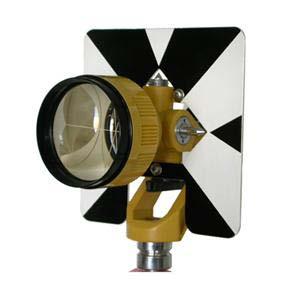
22 PRISM A corner-cube or reflective prism is essential for most Total Stations and EDM. The prism is used to return the transmitted beam to the instrument to allow a distance to be determined by time of flight or phase comparison Total stations allow for the direct input of temperature and pressure and automatic application of meteorological corrections. Most of the current EDM instruments use LASER beams and reflectors The latest models provide for reflector-less measurements, thus improving efficiency for certain applications drastically 22

23 ROUTINE CARE OF TOTAL STATION 23
24 ROUTINE CARE OF TOTAL STATION Before making the first set up of the day, visually inspect the instrument for damage. Check the machined surfaces and the polished faces of the lenses and mirrors. Try the clamps and motions for smooth operation Clean the exterior of the instrument frequently. Any accumulation of dirt and dust can scratch the machined or polished surfaces and cause friction or sticking in the motions. Remove dirt and dust with a clean, soft cloth or with a brush. Clean non-optical parts with a soft cloth or clean chamois Clean the external surfaces of lenses with a fine lens brush and, if necessary, use a dry lens tissue. Do not use silicone-treated tissues because they can damage coated optics. The lens may be moistened before wiping it, but do not use liquids for cleaning. Do not loosen or attempt to clean the internal surfaces of any lens After an instrument has been used in damp or cold situation, use special precautions to prevent condensation of moisture inside the instrument. If the instrument is used in cold weather, leave it in the carrying case in the vehicle during non-working periods rather take it into a heated room. If you store the instrument in a heated room overnight, remove it from the carrying case. If the instrument is wet, bring it into a warm, dry room, remove it from its case and leave it at room temperature to dry it 24
25 VEHICULAR TRANSPORT Transport and store instrument in positions that are consistent with the carrying case design. For example, total station should be carried and stored in their correct position. Many instrument cases indicate the position in which they should be transported Treat tribrachs, prism and tripods with care. Carry them in their shipping cases or cushion them with firm polyfoam or excelsior-filled cases to protect the from jolting or vibrating excessively 25
26 CASING AND UNCASING Before removing an instrument, study the way it is placed and secured in the case. Place it in the same position when you return it to the case. In removing the instrument from the case, carefully grip it with both hands, but do not grip the vertical circle standard or where pressure will be exerted or tubular or circular level vials 26
27 SOURCES OF ERROR IN TOTAL Instrument Errors STATION WORK Plate bubble out of adjustment Horizontal axis not perpendicular to vertical axis Axis of sight not perpendicular to horizontal axis Vertical circular index error Eccentricity of centres Circle graduation errors Errors caused by peripheral equipment 27
28 SOURCES OF ERROR IN TOTAL Natural Errors STATION WORK Wind Temperature effects Refraction Tripod settlement 28
29 SOURCES OF ERROR IN TOTAL Personal Errors STATION WORK Instrument not set up exactly over point Bubbles not centred perfectly Improper use of clamps and tangent screws Poor focusing Overly careful sights Careless plumbing and placement of rod 29
30 MISTAKES Some common mistakes in angle measurement work are: Sighting on, or setting up over the wrong point Calling out or recording an incorrect value Improper focusing of the eyepiece and objective lenses of the instrument Partiality on the tripod, or placing a hand on the instrument when pointing or taking readings 30
31 Thank You & Question and Answer 31
Chapter-2 Direct Measurement Indirect Measurement Method of linear measurement Taping corrections Optical measurement Tachometry EDM Measurement
 Chapter-2 Direct Measurement Indirect Measurement Method of linear measurement Taping corrections Optical measurement Tachometry EDM Measurement 1 2 3 4 5 6 7 Methods There are 3 methods of making linear
Owner's Manual NSL100B BUILDERS LEVEL NSL500B TRANSIT LEVEL
 Owner's Manual NSL100B BUILDERS LEVEL NSL500B TRANSIT LEVEL 1 1. CONTENTS 2. Nomenclature page 3 3. Care and Maintenance page 4 4. Using your Instrument 4.1 Setting up your Instrument page 5 4.2 Stadia
CIV : THEODOLITE ADJUSTMENT
 Unit CIV2202: Surveying 10.1 CIV2202.10: THEODOLITE ADJUSTMENT Table of Contents PREVIEW...2 Introduction...2 Objectives...2 Readings...2 REGULAR CHECKS...2 Tripod...2 Footscrews...2 Tribrach head...3
Owner's Manual. for AUTOMATIC LEVEL. NBL Series. FOR CUSTOMER SERVICE, PARTS & REPAIR, CALL Toll Free:
 Owner's Manual for AUTOMATIC LEVEL NBL Series FOR CUSTOMER SERVICE, PARTS & REPAIR, CALL Toll Free: 1-888-247-1960 1 1. CONTENTS 2. Nomenclature page 3 3. Care and Maintenance page 4 4. Using your Instrument
Cleveland State University
 CVE 212 - Surveying Lab #1 MEASURING ANGLES & DISTANCES WITH A TOTAL STATION EQUIPMENT EDMI and Tripod Single prism mounted on a prism pole Field book Pencil 2 Walkie Talkies INTRODUCTION Recent developments
取扱説明書 /INSTRUCTION MANUAL 自動レベル /AUTOMATIC LEVEL AT-B2/B3/B4 FC10386-A012-02
 取扱説明書 /INSTRUCTION MANUAL 自動レベル /AUTOMATIC LEVEL AT-B2/B3/B4 FC10386-A012-02 SURVEYING INSTRUMENTS INSTRUCTION MANUAL AUTOMATIC LEVEL AT-B2/B3/B4 Thank you for selecting the AT-B2/B3/B4. Please read this
Measurement of Distance and Elevation Equipment and Procedures
 AMRC 2012 MODULE 2 Measurement of Distance and Elevation Equipment and Procedures CONTENTS Overview... 2-1 Objectives... 2-1 Procedures... 2-1 2.1 Introduction to Methods of Distance Measurement... 2-3
Digital Land Surveying And Mapping(DLS&M) Dr. Jayanta Kumar Ghosh Department of Civil Engineering Indian Institute of Technology, Roorkee
 Dr. Jayanta Kumar Ghosh Department of Civil Engineering Indian Institute of Technology, Roorkee") Digital Land Surveying And Mapping(DLS&M) Dr. Jayanta Kumar Ghosh Department of Civil Engineering Indian Institute of Technology, Roorkee Lecture - 17 Total Station Introduction Welcome students, this
Digital Land Surveying And Mapping(DLS&M) Dr. Jayanta Kumar Ghosh Department of Civil Engineering Indian Institute of Technology, Roorkee Lecture - 17 Total Station Introduction Welcome students, this
~.LIETZ ~. LI ETZ INSTRUCTION MANUAL DOUBLE CENTER THEODOLITE TM-20C THE LIETZ COMPANY E. Del Arno Blvd. Carson, Ca (213)
") ~.LIETZ DOUBLE CENTER THEODOLITE TM-20C INSTRUCTION MANUAL f~, ~. LI ETZ THE LIETZ COMPANY 1645 E. Del Arno Blvd. Carson, Ca. 90746. (213)537-0410 n INSTRUMENT NOMENCLATURE cr, il (~ iíl i) Ii: in CD CD
~.LIETZ DOUBLE CENTER THEODOLITE TM-20C INSTRUCTION MANUAL f~, ~. LI ETZ THE LIETZ COMPANY 1645 E. Del Arno Blvd. Carson, Ca. 90746. (213)537-0410 n INSTRUMENT NOMENCLATURE cr, il (~ iíl i) Ii: in CD CD
Leveling. 3.1 Definitions
 Leveling 3.1 Definitions Leveling is the procedure used to determine differences in elevation between points that are remote from each other. Elevation is a vertical distance above or below a reference
Automatic Level NP-732
 INSTRUCTIONS FOR USE Automatic Level NP-732 Contents Before use 2 1.Nomenclature. 3 2.Operation....4 2-1 Preparing before surveying...4 2-2 Surveying method..........5 2-2-1 Measuring altitude difference...5
GEOMATICS ENGINEERING
 GEOMATICS ENGINEERING CHAPTER 2 Direct and Indirect Distance Measurement Methods Distance Measurement Methods Equipment Classification Usage Fieldwork procedure Booking system Adjustment and plotting Introduction
Islamic University of Gaza Civil Engineering Department Surveying II ECIV 2332
 Islamic University of Gaza Civil Engineering Department Surveying II ECIV 2332 By Belal Almassri Chapter 6 Electronic Distance Measurement EDM - Introduction. - Electro-Optical Instrument. - Microwave
Kalinka Optics Warehouse User Manual Kobra AK Side Mount Red Dot Sight Manual
 Kalinka Optics Warehouse User Manual www.kalinkaoptics.com Kobra AK Side Mount Red Dot Sight Manual CONTENTS 1. Introduction... 4 2. Purpose... 4 3. Specifications... 4 4. Components and Equipment Provided...
Carlson CR Robotic/Reflectorless Total Station
 0 West Second Street Suite 00 Maysville, KY 4056 www.carlsonsw.com Phone: 606-564-508 Fax: 606-564-64 Type starts around here Carlson CR Robotic/Reflectorless Total Station Calibration Overview Congratulations
22X Builder s Transit Level Model No Instruction Manual
 2595H 7/29/09 10:15 AM Page 1 22X Builder s Transit Level Model No. 40-6910 Instruction Manual Congratulations on your choice of this 22X Builder s Transit Level. We suggest you read this instruction manual
LT8-300LTU Owner s Guide
 LT8-300LTU Owner s Guide LT8-300LTU LT8-300LTULP FOR CUSTOMER SERVICE, PARTS AND REPAIR CALL (765) 581-4097 www.davidwhite.us.com IMPORTANT: IMPORTANT : IMPORTANTE: Read Before Using Lire avant usage Leer
Fig. 1. instrument is in the case
 1. Applications The NETH503 series Electronic Theodolite has an optical incremental grading system which features digital angle measurements. It can achieve measurement, calculating, display and memory
22X Builder s Level Model No Instruction Manual
 2594H 7/29/09 10:12 AM Page 1 22X Builder s Level Model No. 40-6900 Instruction Manual Congratulations on your choice of this 22X Builder s Level. We suggest you read this instruction manual thoroughly
SURVEYING 1 CE 215 CHAPTER -3- LEVEL AND LEVELING
 Civil Engineering Department SURVEYING 1 CE 215 CHAPTER -3- LEVEL AND LEVELING 1 CHAPTER -3- LEVEL AND LEVELING 2 1 CONTENTS 1. Level instrument 2. Bubble 3. Tripod 4. Leveling staff 5. Definitions 6.
DWT-10 Instruction Manual
 DWT-10 Instruction Manual For Customer Service Call (781) 848-7702 or Fax (781) 848-8022 Congratulations on your choice of this David White Electronic Digital Transit. We suggest that you read this instruction
2-7x32. Instruction manual
 In the event that you should require service for your Nikon RIFLESCOPE, please send it directly to: Nikon Scope Service 841 Apollo Street, Suite 100 El Segundo, CA. 90245-4721 1-800-Nikon SV. 2-7x32 Manufacturer:
DETERMINATION OF AREA OF POLYGON BY CHAIN AND CROSS STAFF SURVEY 1. AIM:
 Expt. No: 2 Date: DETERMINATION OF AREA OF POLYGON BY CHAIN AND CROSS STAFF SURVEY 1. AIM: To determine the area of a given field with define boundary by conducting cross staff survey. 2. INSTRUMENTS REQUIRED:
saxon Instruction Manual saxon Grandeur Brass Telescope High quality optics
 saxon High quality optics Instruction Manual saxon Grandeur Brass Telescope WARNING! Do not use the telescope to look at the sun without an appropriate solar filter. Looking at or near the sun can result
GT-510/510L series Instruction Manual
 GT-510/510L series Instruction Manual NO.3.20110322 Contents 1 INSTRUMENT FEATURES... - 1 2 QUICK GUIDE... - 2 2.1 INSTRUMENT PACKING...- 2 2.2 NAME OF INSTRUMENT PARTS...- 3 2.3 UNPACK AND STORAGE...-
CASSINI CQR-800 OPERATING INSTRUCTIONS INTRODUCTION
 HQR-800 CASSINI CQR-800 OPERATING INSTRUCTIONS INTRODUCTION CONGRATULATIONS ON YOUR PURCHASE OF THE CASSINI CQR-800 TELESCOPE. THIS TELESCOPE HAS BEEN PRODUCED TO PRECISE SPECIFICATIONS. PRIOR TO USING
SURVEYING 1 CE 215 CHAPTER -3- LEVEL AND LEVELING
 Civil Engineering Department SURVEYING 1 CE 215 CHAPTER -3- LEVEL AND LEVELING 1 CHAPTER -3- LEVEL AND LEVELING 2 1 CONTENTS 1. Level instrument 2. Bubble 3. Tripod 4. Leveling staff 5. Definitions 6.
NcSTAR SHOOTER II SERIES SCOPE
 NcSTAR SHOOTER II SERIES SCOPE Congratulations on the purchase of your New NcSTAR Shooter II Series Scope! The Shooter II Series of scopes gives you many great options, so you can choose the scope that
MARINE BINOCULARS ZHUMELL 7X50 MARINE BINOCULARS WITH COMPASS AND RETICLE
 0 OWNER S MANUAL MARINE BINOCULARS ZHUMELL 7X50 MARINE BINOCULARS WITH COMPASS AND RETICLE 75 W 60 W 30 W 45 W Zhumell customers know that there are plenty of ways to experience the world. They also understand
C A S S I N I TRACKER
 C A S S I N I TRACKER ASTRONOMICAL REFLECTOR T ELESCOPE SERIES #C-80080TR #C-1100102TR #C-1000120TR #C-1000120TREF #C-900135TR COSMO BRANDS INC. WWW.COSMOSOPTICS.COM 2 CASSINI REFLECTING TELESCOPE OPERATING
GY 301: Geomorphology Lab 5: Total Station Mapping Project
 Introduction This is the capstone lab project for GY 301. With the assistance of your team member (4 people per team), you will use the Total Station to survey a topographic map of the campus area (see
SURVEYING INSTRUMENTS DT7C DT20C. Electronic Digital Theodolite OPERATOR'S MANUAL
 SURVEYING INSTRUMENTS DT7C DT20C Electronic Digital Theodolite OPERATOR'S MANUAL This is the mark of the Japan Surveying Instruments Manufacturers Association. SURVEYING INSTRUMENTS DT7C DT20C Electronic
EE 1/3.5х14 U EE 1/3.5х14 U
 EE 1/3.5х14 U EE 1/3.5х14 U EE 1/3.5х14 U Table of contents 14 Item No. 1. 2. 3. 4. 5. 6. 7. 8. 9. Section Description of sight Purpose Specification Complete set Design and Principle of Operation Rules
DIGITAL ABBE REFRACTOMETER INE-WYA-2S OPERATING INSTRUCTION PLEASE READ THIS MANUAL CAREFULLY BEFORE OPERATION
 DIGITAL ABBE REFRACTOMETER INE-WYA-2S OPERATING INSTRUCTION PLEASE READ THIS MANUAL CAREFULLY BEFORE OPERATION 3, Hagavish st. Israel 58817 Tel: 972 3 5595252, Fax: 972 3 5594529 mrc@mrclab.com MRC.11.16
COMMODORE BRASS TELESCOPE ZHUMELL COMMODORE BRASS TELESCOPE
 3 0 15 15 E OWNER S MANUAL COMMODORE BRASS TELESCOPE ZHUMELL COMMODORE BRASS TELESCOPE 5 W 60 W 30 W 45 W Zhumell customers know that there are plenty of ways to experience the world. They also understand
Measurement of Horizontal Distances. the distance between two points means the horizontal distance
 Measurement of Horizontal Distances the distance between two points means the horizontal distance Pacing Mechanical Devices Taping * Tachymetric Photogrammetric * Electronic Distance Measurement (EDM)
FOCUS 30/FOCUS 35 Field Calibration with Survey Pro Field Software
 GeoInstruments Application Note June 25th, 2015 FOCUS 30/FOCUS 35 Field Calibration with Survey Pro Field Software Summary: This support note outlines the procedure which should be followed to calibrate
Surveying Prof. Bharat Lohani Indian Institute of Technology, Kanpur. Module - 5 Lecture - 3 Theodolites and Total Stations
 Surveying Prof. Bharat Lohani Indian Institute of Technology, Kanpur Module - 5 Lecture - 3 Theodolites and Total Stations (Refer Slide Time: 00:31) Welcome to another lecture on basic surveying. This
PLI Support Guide: Robotic Total Station Field Calibration
 PLI Support Guide: Robotic Total Station Field Calibration Summary: This manual will instruct you on how to properly calibrate your Trimble Robotic Total Station using Trimble Access. Your instrument must
BINOCULAR. 50 mm Tactical Binocular Manual HD R/T
 50 mm Tactical Binocular Manual HD R/T The Viper Tactical Binocular Built on a tough, durable roof prism design, the 50 mm Viper HD R/T binocular has brilliant optics that can be relied upon in demanding
Cleveland State University
 CVE 212 - Surveying Lab #6 MEASURING ISTANCES USING STAIA METHOS EQUIPMENT Transit or theodolite with stadia hairs and tripod Philadelphia leveling rod Field book No. 3 drafting pencil INTROUCTION When
Directions for use
 Directions for use 40070 40080 60050 70060 70076 80060 90060 900114 Fig. 1 Fig. 1A Fig. 2 Fig. 3 Fig. 4 Fig. 5 Fig. 6 Fig. 7 english ENGLISH DIRECTIONS FOR USE 1 Tripod Leg 2 Tripod Leg Adjusting Screw
UNIT-4 THEODOLITE SURVEYING
 UNIT-4 THEODOLITE SURVEYING The Theodolite The measurement of horizontal and vertical angles and it is the most precise instrument designed for points on line, prolonging survey lines, establishing grades,
Fig. 8.1 illustrates the three measurements. air medium A. ray 1. air medium A. ray 2. air medium A. ray 3. Fig For Examiner s Use
 9 9 9 14 8 In an optics lesson, a Physics student traces the paths of three s of light near the boundary between medium A and. The student uses a protractor to measure the various angles. Fig. 8.1 illustrates
National 3 Waves and Radiation
 What is a wave? National 3 Waves and Radiation 1. Wave Properties The basic definition Waves are a way of transporting energy from one place to another. They do this through some form of vibration. We
Surveying Prof. Bharat Lohani Indian Institute of Technology, Kanpur. Module 5 Lecture 1
 Surveying Prof. Bharat Lohani Indian Institute of Technology, Kanpur (Refer Slide Time: 00:20) Module 5 Lecture 1 Welcome to this another lecture on basic surveying. Today we are going to start a new module.
COPYRIGHTED MATERIAL INTRODUCTION CHAPTER 1
 CHAPTER 1 INTRODUCTION 1.1 INTRODUCTION We currently live in what is often termed the information age. Aided by new and emerging technologies, data are being collected at unprecedented rates in all walks
5-25x56 PMII PSR With Double Turn
 Page 1 of 20 5-25x56 PMII PSR 5-25x56 PMII PSR With Double Turn Page 3 of 20 1. Scope description... 5 1.1 Introduction... 5 1.2 Safety instructions... 5 2. Technical data... 6 2.1 General data... 6 2.2
Surveying Prof. Bharat Lohani Department of Civil Engineering Indian Institute of Technology, Kanpur. Module - 3 Lecture - 4 Linear Measurements
 Surveying Prof. Bharat Lohani Department of Civil Engineering Indian Institute of Technology, Kanpur Module - 3 Lecture - 4 Linear Measurements Welcome again to this another video lecture on basic surveying.
Pulse Laser Station NPL-302 Series
 Pulse Laser Station NPL-302 Series Instruction Manual NPL-332 NPL-352 NPL-362 H163E 05.10.TF.9 Contact Information Nikon-Trimble Co. Limited Copyright and Trademarks 2005, Nikon-Trimble Co. Limited. All
The 36mm Solo R/T Tactical monocular delivers bright images, is compact, easy to handle, and designed for hard use.
 The 36mm Solo R/T Tactical monocular delivers bright images, is compact, easy to handle, and designed for hard use. Diamond Checker Grip Objective Lens Image Focus Flared, Fold-down Eyecup Eyepiece Rubber
Basic Operation Adjust the eyecup
 Objective Lens Image Focus Wheel Reticle Focus Wheel Ocular Lens The Recon R/T Built to handle the roughest conditions, this compact tactical optic is designed to provide field surveillance and range estimation
H050 E 97.1.DF.2. Automatic Levels AS-2 / AS-2C
 H050 E 97.1.DF.2 Automatic Levels AS-2 / AS-2C ikoninstruction Manual Thank you for purchasing the Nikon automatic levels AS-2/AS-2C. The AS-2/AS-2C is designed for high precision surveys in civil engineering
Assembly Manual for the Brevard Astronomical Society 16 inch F4.5 Dobsonian Telescope Brevard Astronomical Society P.O. Box 1084 Cocoa, FL 32922
 BAS 16 Telescope Manual Rev 1 Assembly Manual for the Brevard Astronomical Society 16 inch F4.5 Dobsonian Telescope Brevard Astronomical Society P.O. Box 1084 Cocoa, FL 32922 TABLE OF CONTENTS SECTION
Telescope. 1. Read these instructions carefully and familiarise yourself with the procedure before assembling the unit.
 Telescope a Simple assembly instructions- Please keep for future reference IMPORTANT 1. Read these instructions carefully and familiarise yourself with the procedure before assembling the unit. 2. Check
PULSE TOTAL STATION GPT-3000(L)N SERIES
N SERIES") GPT-3000(L)N SERIES PULSE TOTAL STATION Best Performance Non-prism measurement Features Visible Laser Pointer GPT-3000(L)N Series uses both an invisible Pulse Laser Diode for distance measurement and a
GPT-3000(L)N SERIES PULSE TOTAL STATION Best Performance Non-prism measurement Features Visible Laser Pointer GPT-3000(L)N Series uses both an invisible Pulse Laser Diode for distance measurement and a
1 YEAR LIMITED WARRANTY TELESCOPES
 1 YEAR LIMITED WARRANTY TELESCOPES BARSKA Optics, as manufacturer, warrants this new precision optical product to be free of original defects in materials and/or workmanship for the length of time specified
AL 22 / 26 Classic Инструкция по использованию FIN RUS / / Rev.01.07
 080.82 / 080.83 / Rev.01.07 D GB NL DK F E I PL FIN RUS Bedienungsanleitung 3-8 Operating instructions 9-14 Gebruiksaanwijzing 15-20 Betjeningsvejledning 21-26 Mode d emploi 27-32 Instrucciones para su
The 50mm Viper R/T binocular is equipped with the Vortex R/T Ranging reticle, designed to assist the user in calculating distances.
 With a tough and durable roof prism design and brilliant optics, the Viper R/T can be relied on in the worst conditions thanks to Vortex s premium XD glass and XR lens coatings. The 50mm Viper R/T binocular
SOLO R/T TACTICAL MONOCULAR
 SOLO R/T TACTICAL MONOCULAR MANUAL 36 mm Model The Vortex Solo Tactical R/T Monocular The 36mm Solo Tactical R/T monocular delivers bright images, is compact, and easy to handle. Built to withstand use
Welcome to purchase and use our products and thank you for your confidence in our company s products!
 PREFACE Dear users: Welcome to purchase and use our products and thank you for your confidence in our company s products! It has been our target to innovate the international-level advanced surveying instrument
Interferometer for Squareness measurement
 F Interferometer for Squareness measurement The deviation of squareness of two machine axes can be measured as follows: 1. The straightness of a machine axis is measured. 2. The Angular reflector stops
CE 271 Spring Survey Camp
 PART IV LEVELING A. Importance of Leveling The determination of elevations with a surveying instrument, which is known as leveling, is a relatively simple but extraordinarily important process. B. Definitions
Climate & Earth System Science. Introduction to Meteorology & Climate. Chapter 05 SOME OBSERVING INSTRUMENTS. Instrument Enclosure.
 Climate & Earth System Science Introduction to Meteorology & Climate MAPH 10050 Peter Lynch Peter Lynch Meteorology & Climate Centre School of Mathematical Sciences University College Dublin Meteorology
Physics 313: Laboratory 8 - Polarization of Light Electric Fields
 Physics 313: Laboratory 8 - Polarization of Light Electric Fields Introduction: The electric fields that compose light have a magnitude, phase, and direction. The oscillating phase of the field and the
National Optical & Scientific Instrument Inc Tri-County Parkway Schertz, Texas Phone (210) Fax (210)
 Fax (210)") National Optical & Scientific Instrument Inc. 6508 Tri-County Parkway Schertz, Texas 78154 Phone (210) 590-9010 Fax (210) 590-1104 INSTRUCTIONS FOR SHOP MICROSCOPES MODEL NUMBERS 186 187 188 189 National
National Optical & Scientific Instrument Inc. 6508 Tri-County Parkway Schertz, Texas 78154 Phone (210) 590-9010 Fax (210) 590-1104 INSTRUCTIONS FOR SHOP MICROSCOPES MODEL NUMBERS 186 187 188 189 National
COPYRIGHTED MATERIAL INTRODUCTION CHAPTER 1
 CHAPTER 1 INTRODUCTION 1.1 INTRODUCTION We currently live in what is often termed the information age. Aided by new and emerging technologies, data are being collected at unprecedented rates in all walks
Spotting Scope Instruction Manual
 Spotting Scope Instruction Manual Here are the Main Parts of Your orbitor OR7030 B A C A. Telescope Tube F E D B. Dew Shield I C. Eyepiece G D. Diagonal Mirror E. Focuser F. Mount Lock Knob H G. Aiming
LEAPERS, INC. RED/GREEN DOTS
 LEAPERS, INC. 1 RED/GREEN DOTS range estimating scopes UTG reticle intensified scopes TOTAL SOLUTION TO YOUR NEEDS -COMMITMENT TO BEST QUALITY, BEST VALUE AND BEST SERVICEwww.LEAPERS.com 32700 Capitol
WATTS MICROPTIC ALIDADE OPERATING INSTRUCTIONS 20-7
 WATTS MICROPTIC ALIDADE 20-7 OPERATING INSTRUCTIONS WATTS Operating Instructions for the WATTS MICROPTIC ALIDADE SA100 SA101 RANK PRECISION INDUSTRIES METROLOGY DIVISION Survey Equipment Sales Langston
Electron Microscopy Sciences INSTRUCTION MANUAL. Stereo Microscopes Non-illuminated Stands
 Electron Microscopy Sciences 1 INSTRUCTION MANUAL Stereo Microscopes Non-illuminated Stands Model GL7-207: Binocular, 6.5:1 Zoom Ratio 10X to 65X, smooth ball bearing construction and Model GL7-307: Trinocular,
CASSINI CQR-120 OPERATING INSTRUCTIONS
 CASSINI CQR-120 OPERATING INSTRUCTIONS INTRODUCTION CONGRATULATIONS ON YOUR PURCHASE OF THE CASSINI CQR-120 TELESCOPE. THIS TELESCOPE HAS BEEN PRODUCED TO PRECISE SPECIFICATIONS. PRIOR TO USING YOUR NEW
model SKT05 SKT05L Toll Free: (855) IMPORTANT: Read Before Using IMPORTANT Lire avant usage IMPORTANTE: Leer antes de usar
 IMPORTANT: Read Before Using IMPORTANT Lire avant usage IMPORTANTE: Leer antes de usar") Operating / Safety Instructions Consignes de fonctionnement / sécurité Instrucciones de funcionamiento y seguridad IMPORTANT: Read Before Using IMPORTANT Lire avant usage IMPORTANTE: Leer antes de usar
Operating / Safety Instructions Consignes de fonctionnement / sécurité Instrucciones de funcionamiento y seguridad IMPORTANT: Read Before Using IMPORTANT Lire avant usage IMPORTANTE: Leer antes de usar
ZENITHSTAR 61 APO. Owner s Manual ver
 ZENITHSTAR 61 APO Owner s Manual ver. 1.1 2017.07 Contents Specification 3 Telescope Diagram 4 Accessories Map 5 Usage 6 Storage and Cleaning 7 Caution and Safety, Optional Equipment 8 Optional Equipment
0.4 s 0.8 s 1.5 s. 2.5 s. 2. A beam of light from a ray box spreads out as shown in the diagram and strikes a plane mirror.
 1. ship is fitted with echo-sounding equipment. pulse of sound is sent downwards from the ship at a speed of 1500 m/s. The seabed is 600m below the ship. How long will it take the pulse of sound to return
x Builders Level Service Manual
 40-690 22x Builders Level Service Manual Item Description Pages.0 Overall Instrument Assembly 2. Main Assembly 2.2 Telescope Assembly 3.3 Base Assembly 4.4 Frame Assembly 5 2.0 Calibration 6-8 2. Vial
Name: Number: Class: Date: What is light? 1. What is the name for all these types of light? 2. What type of light can humans see?
 Name: Number: Class: Date: What is light? Worksheet 1 1. What is the name for all these types of light? 2. What type of light can humans see? 3. What type of light has the longest wavelength? 4. What types
What is the maximum distance I can have the remote sensors from the display?
 What is the maximum distance I can have the remote sensors from the display? The maximum open-air distance is 100 meters in a straight line although you should take into account the environment, distance
ZFK 4 X 25. Description and Utilization Instructions
 1. Clarification of Concept The ZFK 4 x 5 is a telescopic sight with fixed magnification with dual cross hair adjustments, central viewing, and attached mount. ZFK 4 X 5 Description and Utilization Instructions.
2. OPERATIONAL CONDITIONS
 1. INTRODUCTION This device was designed for modern physics labs of colleges and graduate schools. It demonstrates the influence of a magnetic field on light, known as Zeeman Effect, and reveals the behavior
10.3 Vertical reticle
 Circular vial adj. screw Circular vial Tighten the screws equally after the above adjustment. Circular vial adj. screw 10.3 Vertical reticle [Checks] 1 Set the instrument up the tripod and carefully level
SKELESCOPE REFLECTOR TELESCOPE WITH TABLE TOP TRIPOD SK-100 INSTRUCTION MANUAL
 TM SKELESCOPE REFLECTOR TELESCOPE WITH TABLE TOP TRIPOD SK-100 INSTRUCTION MANUAL TABLE OF CONTENTS Introduction Box Contents / Visual Key Diagram Telescope Assembly Setting up Your Telescope Attaching
NEW STANDARD SEXTANT OF THE U. S. NAVY
 NEW STANDARD SEXTANT OF THE U. S. NAVY Director of the United States of America Hydrographic Office has sent to the International Hydrographic Bureau the following data relating to the new Standard Sextant
5-25x56 PMII PSR Illuminated with Double Turn
 Page 1 of 20 5-25x56 PMII PSR Illuminated with Double Turn Page 3 of 20 1. Scope description... 5 1.1 Introduction... 5 1.2 Safety instructions... 5 2. Technical data... 6 2.1 General data... 6 2.2 Dimensions...
RP-100 TELESCOPE Instruction Manual
 2070 5th Avenue Ronkonkoma, NY 11779 Phone: 631-963-5000 Fax: 631-427-6749 For information, call toll-free: 1-800-967-8427 info@carson.com / sales@carson.com / www.carson.com RP-100 TELESCOPE Instruction
WS-7047TWC Wireless 433 MHz Weather Station With Rainfall and Temperature. Instruction Manual
 WS-7047TWC Wireless 433 MHz Weather Station With Rainfall and Temperature Instruction Manual TABLE OF CONTENTS Topic Page Inventory of Contents 2 Additional Equipment 2 Quick Setup 3 Detailed Setup Guide
Optics. Measuring the line spectra of inert gases and metal vapors using a prism spectrometer. LD Physics Leaflets P
 Optics Spectrometer Prism spectrometer LD Physics Leaflets P5.7.1.1 Measuring the line spectra of inert gases and metal vapors using a prism spectrometer Objects of the experiment Adjusting the prism spectrometer.
Physics LESSON PLAN PERFORMANCE OBJECTIVE(S): STUDENTS WILL BE ABLE TO:
: STUDENTS WILL BE ABLE TO:") Physics LESSON PLAN Subject: Physics Grade: 7 12 Date: 6/21/2012 Concept: The wave nature of light, Estimated Time of Lesson: 100 Minutes PERFORMANCE OBJECTIVE(S): STUDENTS WILL BE ABLE TO: (1) Understand
Physics LESSON PLAN Subject: Physics Grade: 7 12 Date: 6/21/2012 Concept: The wave nature of light, Estimated Time of Lesson: 100 Minutes PERFORMANCE OBJECTIVE(S): STUDENTS WILL BE ABLE TO: (1) Understand
15 E OWNER S MANUAL PIRATE SPYGLASS BRING EM NEAR PIRATE SPYGLASS TELESCOPE 5 W 30 W 60 W 45 W
 3 0 15 15 E OWNER S MANUAL PIRATE SPYGLASS BRING EM NEAR PIRATE SPYGLASS TELESCOPE 5 W 60 W 30 W 45 W Zhumell customers know that there are plenty of ways to experience the world. They also understand
Experiment #5: Cauchy s Formula
 Experiment #5: Cauchy s Formula Carl Adams October 14, 2011 1 Purpose This experiment is a continuation of Experiment #4. It is assumed you have an aligned spectrometer. 2 Safety/Protocol 1. The gas discharge
AGES CF600PM. 50 mm Telescope w/ AZ Pan Tilt Mount Instruction Manual. WARNING! SUN HAZARD: Never look directly at the sun with this device.
 AGES CF600PM 50 mm Telescope w/ AZ Pan Tilt Mount Instruction Manual WARNING! SUN HAZARD: Never look directly at the sun with this device. 1 WARNING: Never attempt to observe the sun with this telescope.
C A S S I N I. MODEL : C EQ3 900mm X 135mm COSMO BRANDS INC.
 C A S S I N I MODEL : C-900135EQ3 900mm X 135mm COSMO BRANDS INC. WWW.COSMOSOPTICS.COM 2 C A S S I N I C-900135EQ3 TELESCOPE OPERATING INSTRUCTIONS INTRODUCTION CONGRATULATIONS ON YOUR PURCHASE OF THE
Automatic Level Maintenance Manual SAL-XX W/ AIR DAMPENED COMPENSATOR
 Automatic Level Maintenance Manual SAL-XX W/ AIR DAMPENED COMPENSATOR CST/Berger 2001 SAL 20/24/28/32 PAGE 1 REV. C 071803 Automatic Level Maintenance Manual User Calibration and Testing... 3 Circular
STONEX ELECTRONIC THEODOLITE STT SERIES. Instruction Manual
 STONEX ELECTRONIC THEODOLITE STT SERIES Instruction Manual PREFACE Dear users: Welcome to purchase and use our products and thank you for your confidence in our company s products! It has been our target
Physics 476LW Advanced Physics Laboratory Michelson Interferometer
 Physics 476LW Advanced Physics Laboratory Michelson Interferometer Introduction An optical interferometer is an instrument which splits a beam of light into two beams, each beam follows a different path
PRIMARY CONTROL SURVEYS
 STATE CONTROL SURVEY SPECIFICATIONS FOR PRIMARY CONTROL SURVEYS Now Obsolete Caution: This document has been prepared by scanning the original Specifications for Primary Control Surveys - 1984 and using
-I g in y e SURVEYING-I rv u S
 SURVEYING-I Modern Surveying Chains & other Equipment Measuring Distance The historical method measuring distance is surveying chain. for the One of the first chains used in the U.S. was the Gunter s chain.
RECON. How to Setup the Telescope to Observe. This guide will show you how to setup your telescope for observing. Written By: Brittany McCrigler
 RECON How to Setup the Telescope to Observe This guide will show you how to setup your telescope for observing. Written By: Brittany McCrigler 2017 recon.dozuki.com Page 1 of 30 INTRODUCTION This guide
CONTENT FORWORDS... 1 FEATURES... 5 PRECAUTIONS BRIEF INTRODUCTION... 7
 FORWORDS Congratulations on purchasing Total Station CTS-662 series. This manual will give a detailed and complete instruction about this total station. Please read it carefully before use. 1 CONTENT FORWORDS...
The Accuracy of Electronic Distance Meters over Short Distances
 263 The Accuracy of Electronic Distance Meters over Short Distances Braun, J., Štroner, M. and Urban, R. Czech Technical University in Prague, Faculty of Civil Engineering, Department of Special Geodesy,