JDV CONTROL VALVES CO., LTD. JCT/JCTM Series 3/4 Way Trunnion Type Valve Manual
|
|
|
- Belinda Juliana Hall
- 5 years ago
- Views:
Transcription
1 JCT/JCTM Series 3/4 Way Trunnion Type Valve Manual 1. Please read this manual before installation or servicing. 2. Before installing or servicing, please ensure the line pressure has been relieved and any hazardous fluid has been drained or purged from the system. 1. Please do not use the valve exceeding its designed pressure range. 2. Please do not use the valve exceeding its designed temperature range. RECEPTION Check following points when receiving the goods. 1. Check if there is any break on the packing. All valves should be well packed before shipment in order to prevent from any possible damage caused during the transportation. 2. Check if the valves are correct specification consisted with the order stated. STORAGE Please follow below points to check valves in case the valves will not be installed immediately. 1. The valves should be stored in dry and clean indoor. 2. The surface of valve ends should be greased properly for the protection. 3. The ports of valve should be well sealed by plastic caps or tapes for avoiding any dirt entering valve to damage inner parts. 1 of 14

2 INSTALLATION 1. Before installing, check all valves and mating flanges to ensure gasket surfaces are free from defects. 2. Make sure all valves and lines are clean without any dirt or debris, which may cause valve seals damaged. 3. Checking the piping is the alignment with appropriate supports. It is not recommended to install valves to improperly positioned pipes. 4. Follow the flow arrows of valve body for making sure the valve will be installed in the correct direction of pipeline. Before installing, inspect the valve by visual for avoiding any damages. 5. Install the valve to the pipeline and tighten bolts properly. Notice that the over tightening of any side may cause the leakage. OPERATION Port Type Options 2 of 14

3 For Manual Operation Example: Flow direction is required in T-Port A Type AL (See the Port Type Options above) From AF (Air Failure) to AL (Air in Turn Left) Step 1. Stem direction should be stopped as Pic. A Step 2. Put the lever handle on stem and turn it in anti-clockwise till the stem stops as the Pic. B. <Pic. A> <Pic. B> From AL to AF Step 1. Stem direction should be stopped as Pic. B Step 2. Put the lever handle on stem and turn it in clockwise till the stem stops as the Pic. A. Example: Flow direction is required in L-Port F Type FR (See the Port Type Options above) From AF (Air in Turn Left) to FR (Air in Turn Right) Step 1. Stem direction should be stopped as Pic. C. Step 2. Put the lever handle on stem and turn it in clockwise till the stem stops as the Pic. D. <Pic. C> <Pic. D> From FR to AF. Step 1. Stem direction should be stopped as Pic. D. Step 2. Put the lever handle on stem and turn it in anti-clockwise till the stem stops as the Pic. C. The over turning may break the lever handle, stopper or stem to cause the seat leakage, or even more may injure the operator. Therefore, it is strongly suggested to lock the lever handle when the valve is not operated. 3 of 14

4 For Gear Operation Example: Flow direction is required in T-Port A Type AL (See the Port Type Options above) From AF (Air Failure) to AR (Air in Turn Right) Step 1. Valve position should be stopped as Pic. E and the direction shown in gear box should be as Pic. G. Step 2. Follow the turning direction on the handwheel of gear box and turn the handwhell till it stops as the Pic. H. <Pic. E> <Pic. F> <Pic. G> <Pic. H> From AR to AF Step 1. Valve position should be stopped as Pic. F and the direction shown in gear box should be as Pic. (H). Step 2. Follow the turing direction on the handwheel of gear box and turn the handwhell till it stops as the Pic. G. Example: Flow direction is required in L-Port E Type ER (See the Port Type Options above) From AF (Air Failure) to ER (Air in Turn Right) Step 1. Valve position should be stopped as Pic. I and the direction shown in gear box should be as Pic. K. Step 2. Follow the turning direction on the handwheel of gear box and turn the handwhell till it stops as the Pic. H. <Pic. I> <Pic. J> <Pic. K> <Pic. L> 4 of 14
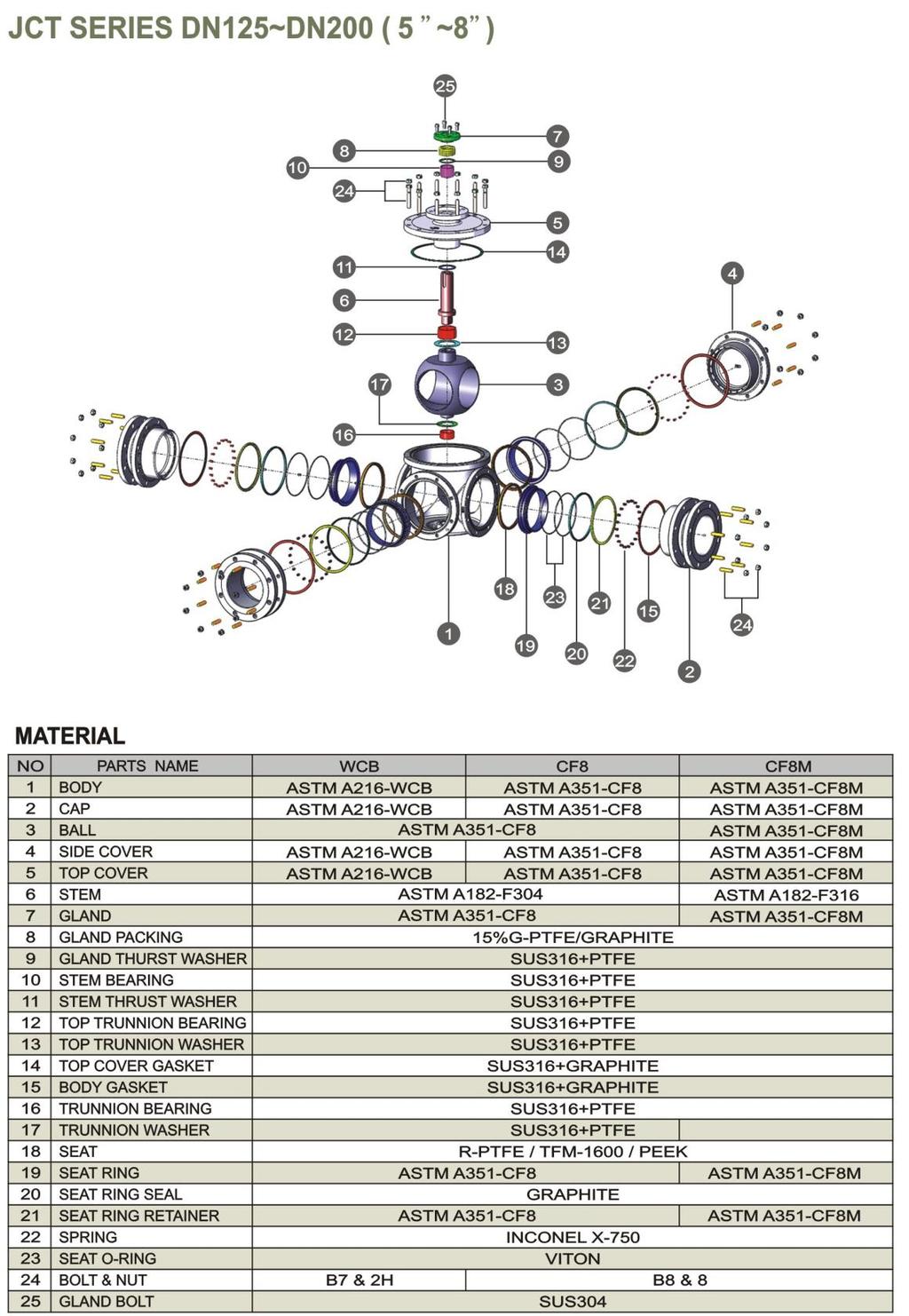
5 From ER to AF Step 1. Valve position should be stopped as Pic. J and the direction shown in gear box should be as Pic. L. Step 2. Follow the turing direction on the handwheel of gear box and turn the handwhell till it stops as the Pic. K. GENERAL MAINTENACE It is recommended to observe the valves periodically for ensuring the system under the proper performance. Please follow the instructions and refer the parts list as below if it is necessary to disassemble the valve. Please refer parts drawing in (Figure A) when dissembling and assembling. DISASSEMBLING For Soft-Seated Type DN40~DN100( 1-1/2 ~ 4 ) 1. Before removing the valve from pipeline, ensure the line pressure and dangerous media have been relieved. Also make sure the temperature in pipeline and valve has been cooled down to be safe. 2. Turn the valve to half CLOSE position in 45 to avoid the pressure in the valve has not been relieved. 3. Remove the valve from the pipeline. 4. Loose either side of Bolts & Nuts(21) of combination, and then remove Cap(2) set. Take out Seat Ring(17), Seat Ring Seal(18), Seat Ring Retainer(19), Spring(20) and Body Gasket(13). Repeat same steps to dismantle another two sides of Cap(2) set and Side Cover(4) set. 5. Remove Snap Catch(23) and Handle(25). Loose Gland Bolt(24), then take out Travel Stop(22) and Gland(6). 6. Loose Bolts & Nuts(21), then take out Top Cover(5) with Gland Packing(7), Gland Thrust Washer(8) and 5 of 14
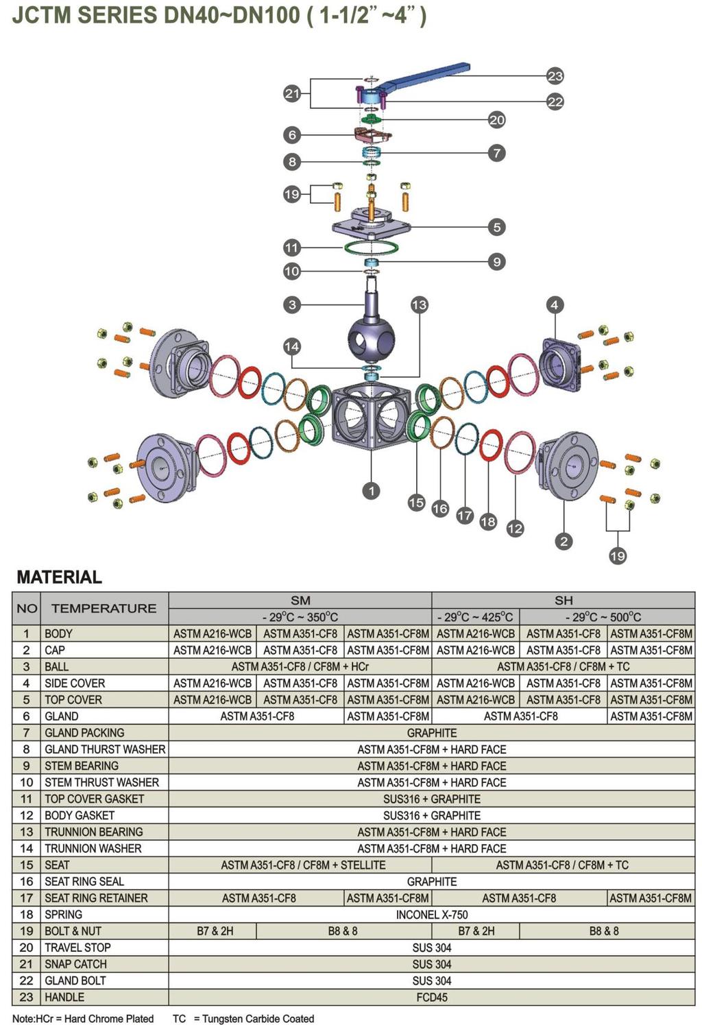
6 Trunnion O-Ring(9). 7. Take out Stem Bearing(10), Stem Thrust Wahser(11), Ball(3), Trunnion Washer(15), Trunnion Bearing(14) from Body(1). For Soft-Seated Type DN125~DN200( 5 ~ 8 ) 1. Before removing the valve from pipeline, ensure the line pressure and dangerous media have been relieved. Also make sure the temperature in pipeline and valve has been cooled down to be safe. 2. Turn the valve to half CLOSE position in 45 to avoid the pressure in the valve has not been relieved. 3. Remove the valve from the pipeline. 4. Loose either side of Bolts & Nuts(24) of combination, and then remove Cap(2) set. Take out Seat Ring(19), Seat Ring Seal(20), Seat Ring Retainer(21), Spring(22) and Body Gasket(15). Repeat same steps to dismantle another two sides of Cap(2) set and Side Cover(4) set. 5. Remove Gland Bolt(25) and take out Gland(7). 6. Loose Bolts & Nuts(24), then take out Top Cover(5) with Gland Packing(8), Gland Thrust Washer(9) and Stem Bearing(10). 7. Take out Stem(6), Stem Thrust Washer(11), Top Trunnion Bearing(12) and Top Trunnion Washer(13) first, then take out Ball(3), Trunnion Washer(17), Trunnion Bearing(16) from the Body(1). For Metal-Seated Type DN40~DN100(1-1/2 ~ 4 ) 1. Before disassembling the valve from pipeline, ensure the line pressure and dangerous media have been relieved. Also make sure the temperature in pipeline and valve has been cooled down to be safe. 2. Turn the valve to half CLOSE position in 45 to avoid the pressure in the valve has not been relieved. 3. Remove the valve from pipeline. 4. Loose either side Bolts & Nuts(19) of combination, and then remove Cap(2) set. Take out Seat (15), Seat Ring Seal(16), Seat Ring Retainer(17), Spring(18) and Body Gasket(12). Repeat same steps to 6 of 14
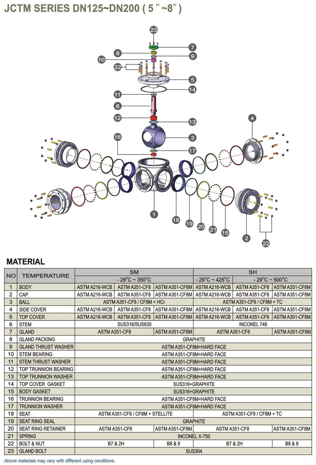
7 dismantle another two sides of Cap(2) set and Side Cover(4) set. 5. Remove Snap Catch(21) and Handle(23). Loose Gland Bolt(22), then take out Travel Stop(20) and Gland(6). 6. Loose Bolt & Nuts(19), then take out Top Cover(5) with Gland Thrust Washer(8) and Gland Packing(7). 7. Take out Stem Bearing(9), Stem Thrust Washer(10), then take out Ball(3), Trunnion Washer(14), Trunnion Bearing(13) from the Body(1). For Metal-Seated Type DN125~DN200( 5 ~ 8 ) 1. Before disassembling the valve from pipeline, ensure the line pressure and dangerous media have been relieved. Also make sure the temperature in pipeline and valve has been cooled down to be safe. 2. Turn the valve to half CLOSE position in 45 to avoid the pressure in the valve has not been relieved. 3. Remove the valve from pipeline. 4. Loose either side of Bolts & Nuts(22) of combination, and then remove Cap(2) set. Take out Seat (18), Seat Ring Seal(19), Seat Ring Retainer(20), Spring(21) and Body Gasket(15). Repeat same steps to dismandtle another two sides of Cap(2) set and Side Cover(4) set. 5. Remove Gland Bolt(23) and take out Gland(7) 6. Loose Bolts & Nuts(22), then take out Top Cover(5) with Gland Packing(8), Gland Thrust Washer(9) and Stem Bearing(10). 7. Take out Stem(6), Stem Thrust Washer(11), Stem Bearing(10), Top Trunnion Bearing(12) and Top Trunnion Washer(13) first, then take out Ball(3), Trunnion Washer(17), Trunnion Bearing(16) from Body(1). ASSEMBLING For Soft-Seated Type DN40~DN100(1-1/2 ~ 4 ) 1. Make sure the disassembled Ball(3) and Seat Ring(17) is completely, and the sealing surface is clean 7 of 14
8 and free from defects. 2. Insert Trunnion Bearing(14) and Trunnion Washer(15) into Body(1), Then insert Ball(3), Stem Thrust Washer(11), Stem Bearing(10), Top Cover Gasket(12) into Body(1). 3. Put Top Cover(5) into the top of Body(1) and Tighten Bolt(21). Insert Trunnion O-Ring(9), Gland Thrust Washer(8), Gland Packing(7) into Top Cover(5) in sequence. 4. Insert Gland(6), Travel Stop(22), Handle (25) into Top Cover(5) and tighten Gland Bolt(24). 5. Inset Spring(20), Seat Ring Retainer(19), Seat Ring Seal(18) and Seat Ring (17) into Cap(2) and Side Cover(4) to be a set. 6. Insert Body Gasket(13) into Body(1), then assemble the Cap(2) set and Side Cover (4) set to the four sides of Body(1) and tighten Bolts & Nuts(21). Notice the JDV logo on the Side Cover(4) is on the upside. For Soft-Seated Type DN125~DN200( 5 ~ 8 ) 1. Make sure the disassembled Ball(3) and Seat Ring(17) is completely, and the sealing surface is clean and free of defects. 2. Insert Trunnion Bearing(16) and Trunnion Washer(17) into Body(1), Then insert Ball(3), Top Trunnion Washer(13), Top Trunnion Bearing(12), Stem(6), Stem Thrust Washer(11), Top Cover Gasket(14) into Body(1). 3. Put Top Cover(5) into the top of Body(1) and Tighten Bolts & Nuts(24). Insert Stem Bearing(10), Gland Thrust Washer(9), Gland Packing(8) and Gland(7) into Top Cover(5) and tighten Gland Bolt(25). 4. Insert Spring(22), Seat Ring Retainer(21), Seat Ring Seal(20), Seat Ring (23) and Seat Ring(19) into Cap(2) and Side Cover(4) to be a set. 5. Insert Body Gasket(15) into Body(1), then assemble the Cap(2) set and Side Cover (4) set to the four sides of the Body(1) and tighten Bolts & Nuts(24). Notice the JDV logo on the Side Cover(4) is on the upside. 8 of 14
9 For Metal-Seated Type DN40~DN100(1-1/2 ~ 4 ) 1. Make sure the disassembled Ball(3) and Seat(15) is completely, and the sealing surface is clean and free of defects. 2. Insert Trunnion Bearing(13) and Trunnion Washer(14) into Body(1), Then insert Ball(3), Stem Thrust Washer(10), Stem Bearing(9), Top Cover Gasket(11) into Body(1). 3. Put Top Cover(5) into the top of Body(1) and Tighten Bolts & Nuts(19). Insert Gland Thrust Washer(8), Gland Packing(7) into Top Cover(5). 4. Insert Gland(6), Travel Stop(20), Snap Catch(21), Handle (23) into Top Cover(5) and tighten Gland Bolt(22). 5. Insert Spring(18), Seat Ring Retainer(17), Seat Ring Seal(16) and Seat (15) into Cap(2) and Side Cover(4) to be a set. 6. Insert Body Gasket(12) into Body(1), then assemble the Cap(2) set and Side Cover (4) set to the four sides of Body(1) and tighten Bolts & Nuts(19). Notice the JDV logo on the Side Cover(4) is on the upside. For Metal-Seated Type DN125~DN200(5 ~ 8 ) 1. Make sure the disassembled Ball(3) and Seat(18) is completely, and the sealing surface is clean and free for defects. 2. Insert Trunnion Bearing(16) and Trunnion Washer(17) into Body(1), Then insert Ball(3), Top Trunnion Washer(13), Top Trunnion Bearing(12), Stem(6), Stem Thrust Washer(11), Top Cover Gasket(14) into Body(1). 3. Put Top Cover(5) into the top of Body(1) and Tighten Bolts & Nuts(22). Insert Stem Bearing(10), Gland Thrust Washer(9), Gland Packing(8), Gland(7) into Top Cover(5) and tighten Gland Bolt(23). 4. Insert Spring(21), Seat Ring Retainer(20), Seat Ring Seal(19) and Seat (18) into Cap(2) and Side Cover(4) to be a set. 5. Insert Body Gasket(15) into Body(1), then assemble the Cap(2) set and Side Cover (4) set to the four sides of Body(1) and tighten Bolts & Nuts(22). Notice the JDV logo on the Side Cover(4) is on the upside. 9 of 14
10 TROUBLE SHOOTING Solution Area Description Soft-Seated Metal-Seated 1. Turn the valve to half open 1. Turn the valve to half open position to check if there is any position to check if there is any damage on the contacted damage on the contacted surface of Ball(3) and Seat surface of Ball(3) and Ring(19). Seat(15/18). 2. If no, then the leakage may be 2. If yes, replace damaged Ball(3) Inner Leakage from upstream bore caused by the wear of Seat after long-time operation. Replace the Seat Ring(17/19). and Seat (12/18). Seat Ring Seal (15/18) is necessary to be replaced as long as the valve Seat Ring Seal(18/20) is is disassembled. necessary to be replaced as long as the valve is disassembled. 3. If no, please contact your local agent or JDV. 3. If yes, replace damaged Ball(3) and Seat Ring(17/19). 1. Tighten the Gland Bolts (24/25). 1. Tighten the Gland Bolts (22/23). Leakage from stem 2. If step 1 cannot stop leakage, disassemble valve to replace 2. If step 1 cannot stop leakage, disassemble valve to replace Outer Gland Packing (7/8). Gland Packing (7/8). Leakage from combination between body and cap Replace the Body Gasket (13/15). Replace the Body Gasket (12/15). 10 of 14

11 Figure A 11 of 14
12 12 of 14
13 13 of 14
14 14 of 14
The 505F Series 3/4/5-Way Ball Valve. Standard Features and Benefits. Operating Conditions. Specifications. Options
 The 505F Series //5-Way Ball Valve The 505F is a true multi-way ball valve with balanced fourseat construction. This full port valve is available in a variety of flow plans which can replace multiple two-way
HEAVY DUTY SWING-OUT VALVE
 ISO 900 REGISTERED COMPANY Akron Brass Company. 20 All rights reserved. No portion of this can be reproduced without the express written consent of Akron Brass Company. We will not be responsible for:
HEAVY DUTY SWING-OUT VALVE
 ISO 900 REGISTERED COMPANY HEAVY DUTY SWING-OUT VALVE 52 53 23 5 2 2 3 28 39 NOT USED WITH SZ HANDLE 2 NOT USED WITH SZ HANDLE 5 2 3 7 9 9 Premier Farnell Corporation. 20 All rights reserved. No portion
/2" Heavy Duty Swing-Out
 Premier Farnell Corporation. 0 All rights reserved. No portion of this can be reproduced without the express written consent of Premier Farnell Corporation. ISO 900 REGISTERED COMPANY We will not be responsible
Conversion Kit for: 7620 and 7820 Swing-Out Valves ft-lbs ft-lbs 8835/ ft-lbs
 ISO 900 REGISTERED COMPANY HEAVY DUTY SWING-OUT VALVE 52 53 23 5 2 2 3 28 39 NOT USED WITH SZ HANDLE 2 NOT USED WITH SZ HANDLE 5 2 3 7 9 9 Premier Farnell Corporation. 20 All rights reserved. No portion
Installation, Maintenance and Operating Instructions
 Trunnion-Design Ball Valves 12 20 (DN 300 500) Series 7150 12 (DN 300) Series 730S 12 20 (DN 300 500) Series 7300 14 24 (DN 350 600) Series 9150 14 24 (DN 350 600) Series 9300 Installation, Maintenance
ER2 Short-head Electric Chain Hoist
 O/M NO.SHER2-0903-CE-00 ER2 Short-head Electric Chain Hoist (250kg to 5t) Operation Manual (SHER2M/SHER2SG/SHER2SP) Introduction The KITO Short-head Electric Chain Hoist is intended for effective use in
CV3000 Series. Characterized Insert Control Valves
 CV3000 Series Characterized Insert Control Valves The CV3000 Series is a v-type control valve for precise control allowing high pressure drop capability with straight-through flow and bubble-tight shut
507F. Multi-Port Sanitary Ball Valve. Full Port ISO 5211 Mounting Pad. For Automated & Manual Service. Pharmaceutical. Bio-Technology.
 507F Multi- Sanitary Ball Valve Full ISO 5 Mounting Pad For Automated & Manual Service Pharmaceutical Bio-Technology Cosmetic Food & Beverage The 507F Series //5-Way Sanitary Ball Valve The 507F is a true
product manual H-3220A Benkelman Beam
 05.12 product manual H-3220A Benkelman Beam General The H-3220A Benkelman Beam Apparatus is a convenient and accurate device used for measuring the deflection of flexible pavements under moving wheel
Automatic Level Maintenance Manual SAL-XX W/ AIR DAMPENED COMPENSATOR
 Automatic Level Maintenance Manual SAL-XX W/ AIR DAMPENED COMPENSATOR CST/Berger 2001 SAL 20/24/28/32 PAGE 1 REV. C 071803 Automatic Level Maintenance Manual User Calibration and Testing... 3 Circular
Electron Microscopy Sciences INSTRUCTION MANUAL. Stereo Microscopes Non-illuminated Stands
 Electron Microscopy Sciences 1 INSTRUCTION MANUAL Stereo Microscopes Non-illuminated Stands Model GL7-207: Binocular, 6.5:1 Zoom Ratio 10X to 65X, smooth ball bearing construction and Model GL7-307: Trinocular,
LEAPERS, INC. RED/GREEN DOTS
 LEAPERS, INC. 1 RED/GREEN DOTS range estimating scopes UTG reticle intensified scopes TOTAL SOLUTION TO YOUR NEEDS -COMMITMENT TO BEST QUALITY, BEST VALUE AND BEST SERVICEwww.LEAPERS.com 32700 Capitol
Serie B2.1. Flanged ductile iron ball valve. made in. Application fields. Shut-off valves E U R O P E. 18
 erie B. Flanged ductile iron ball valve BRanDOni made in E U R O P E Application fields WATER CONdITIONING GA EATING INdUTRY FIRE FIGTING www.brandoni.it erie B. eries B. valves are shut-off ball valves
State Unitary Enterprise Production Amalgamation Novosibirsk Instrument-Making Plant PN-6K. Servise Manual
 State Unitary Enterprise Production Amalgamation Novosibirsk Instrument-Making Plant Night Sight PN-6K Servise Manual Contents 1. General directions 4 2. Specifications 5 3. Delivery set 6 4. Safety regulations
xanik API 6D Trunnion Ball Valves
 API 6D Trunnion Ball Valves BV - XANIK SIDE ENTRY TRUNNION BALL VALVES table of contents BALL VALVES INDEX BV - XANIK SIDE ENTRY TRUNION BALL VALVES BV - 3 XANIK BALL VALVE DESIGN FEATURES BV - 4 thru
DMHP3(4)L(T)2A00 Series
L(T)2A00 Series") STANDARDS Valve body: ASME B16.34 Material certification: EN10204-3.1 MTR Quality assurance: ISO 9001:2008 Steel casting: MSS SP-55 Valve marking: MSS SP-25 Valve test: API 598 Direct mount: ISO 5211 End
STANDARDS Valve body: ASME B16.34 Material certification: EN10204-3.1 MTR Quality assurance: ISO 9001:2008 Steel casting: MSS SP-55 Valve marking: MSS SP-25 Valve test: API 598 Direct mount: ISO 5211 End
INSTALLATION INSTRUCTIONS ATV Plow Blade Part Number: (50 ), (54 ), or (60 ) Application: All Terrain Vehicles
, (54 ), or (60 ) Application: All Terrain Vehicles") INSTALLATION INSTRUCTIONS ATV Plow Blade Part Number: 78950 (50 ), 78954 (54 ), or 78960 (60 ) Application: All Terrain Vehicles Your safety, and the safety of others, is very important. To help you make
INSTALLATION INSTRUCTIONS ATV Plow Blade Part Number: 78950 (50 ), 78954 (54 ), or 78960 (60 ) Application: All Terrain Vehicles Your safety, and the safety of others, is very important. To help you make
Important Instructions
 Important Instructions Subject Use With Cabinet Hardmount Trunnion Replacement Cabinet Hardmount 8-60 Pound Washer-Extractors and Kits F77000, F7700, F7700, F7700, F7700, F7700, F9P and F9P WARNING This
Richter Optica. Instructions for Model: S850 Stereo Zoom Microscope
 Richter Optica info@richter-optica.com Instructions for Model: S850 Stereo Zoom Microscope Microscope Head Focus Knob Stage Clips Zoom Knob C-Mount Adapter Eyepiece Focusing Holder Focusing Holder Set
Kalinka Optics Warehouse User Manual Kobra AK Side Mount Red Dot Sight Manual
 Kalinka Optics Warehouse User Manual www.kalinkaoptics.com Kobra AK Side Mount Red Dot Sight Manual CONTENTS 1. Introduction... 4 2. Purpose... 4 3. Specifications... 4 4. Components and Equipment Provided...
Assembly Instructions for the 1-Wire Weather Station V2.0/V3.0
 Assembly Instructions for the 1-Wire Weather Station V2.0/V3.0 Tools and Supplies Required (not included): Phillips screwdriver 3/8" wrench Drill with 5/32" bit "U" type mounting bracket (i.e., part number
E Service E-Series Padlock seires PadlockManual No. Part No. Part No. Part
 E-Series Padlock E Service seires Manual Padlock 0 No. Part No. Part No. Part Padlock body Locking plate Ball bearing 0 Shackle Bumper 0 Socket head screw Mx0 Activator cam Identification plate Spring
Ref. Parts No. Parts Name P A B BS A B BS Remarks Gear Case Assy Gear Case (Inside)
") GR 480 / GR 530 Quantity GR480 GR530 Ref. Parts No. Parts Name P A B BS A B BS Remarks 80-1020-100-00 Gear Case Assy 1 1 1 1 1 1 1 80-1020-101-00 Gear Case (Inside) 1 1 1 1 1 1 2 80-1020-103-00 Gear Case
GR 480 / GR 530 Quantity GR480 GR530 Ref. Parts No. Parts Name P A B BS A B BS Remarks 80-1020-100-00 Gear Case Assy 1 1 1 1 1 1 1 80-1020-101-00 Gear Case (Inside) 1 1 1 1 1 1 2 80-1020-103-00 Gear Case
DN 1/4" to 4" Male, Female BSP - 10 C C Max Pressure : 30 Bars (up to DN1") Specifications : Anti blow-out stem PTFE packing Full bore
 Specifications : Anti blow-out stem PTFE packing Full bore") Size : Ends : Min Temperature : Max Temperature : DN 1/4" to 4" Male, Female BSP - 10 C + 120 C Max Pressure : 30 Bars (up to DN1") Specifications : Anti blow-out stem PTFE packing Full bore Materials
Size : Ends : Min Temperature : Max Temperature : DN 1/4" to 4" Male, Female BSP - 10 C + 120 C Max Pressure : 30 Bars (up to DN1") Specifications : Anti blow-out stem PTFE packing Full bore Materials
Ball Valves. Ball Valves
 Ball Valves Ball Valves -, 0 beon-gil, Seobu-ro, Juchon-myun, Gimhae-si, Gyeongsangnam-do, Korea. TE +--0-0 FAX +---0~ E-mail acevalve@acevalve.co.kr omepage www.acevalve.co.kr Ball Valves Specification
AME Model. (1) Rated flow (l/min (ANR)) Port size (Nominal size B) Weight (kg)
 Rated flow (l/min (ANR)) Port size (Nominal size B) Weight (kg)") Super Mist Separator Series AME Series AME separates and absorbs aerosol state fine oil particles in compressed air and changes the oil lubricating compressed air to oilless equivalent air. It should be
Super Mist Separator Series AME Series AME separates and absorbs aerosol state fine oil particles in compressed air and changes the oil lubricating compressed air to oilless equivalent air. It should be
OPERATING INSTRUCTIONS
 OPERATING and CHANGING Instructions For Models: 8550, 8555, 8560, 8565 READ THESE INSTRUCTIONS THOROUGHLY BEFORE OPERATING THE LOCK OR ATTEMPTING TO CHANGE THE COMBINATION Note: To assure proper operation,
GWC Valve International. Proven technology for individual valve solutions worldwide
 Proven technology for individual valve solutions worldwide TRUNNION MOUNTED BALL VALVES PRESSURE CLASS: ASME 150-2500 API 2000-5000 SIZE RANGE: 2-4 API STANDARDS: 6D & 6A ASME B16.34 Catalog Number TBV-1001
3D Drawing - CARIF 260 BSA
 D Drawing - CARIF 0 BSA DRAWING CODE DRAWING NAME NUMBER ASS000 Basement ASS00 Vice Base ASS00 Vice A ASS00B Vice B ASS00 Frame A ASS00B Frame B ASS000 Frame Cylinder A ASS000B Frame Cylinder B ASS000
DN 1/4" to 4" Male, Female BSP - 10 C C Max Pressure : 40 Bars Specifications : Anti blow-out stem PTFE packing Full bore.
 Size : Ends : Min Temperature : Max Temperature : DN 1/4" to 4" Male, Female BSP - 10 C + 120 C Max Pressure : 40 Bars Specifications : Anti blow-out stem PTFE packing Full bore Materials : Brass Page
Universal type Port size AS13 1F-M3. M3 x 0.5 M5 x 0.8 AS23 1F-01 AS23 1F-02 AS33 1F-02 AS33 1F-03 AS43 1F-04 R 1/8 R 1/4 R 1/4 R 3/8 R 1/2
 Minimizes installation time and cost Reduces the mounting height and enables compact machinery design. Effective area is larger than the former model. Tube swivels 0 Universal type permits 0 piping swivel.
Cooling Water Flow Regulator
 Temperature controlled, indirectly and directly actuated diaphragm valves / seat valves Port size G 3/8 to G DN 0 to DN 0 ontinuous regulation High accuracy No auxiliary energy required Technical data
INDEX OF ILLUSTRATIONS
 INDEX OF ILLUSTRATIONS FIG 3.1.1 FIG 3.1.2 FIG 3.1.3 FIG 3.2.1 FIG 3.2.2 FIG 3.2.3 FIG 3.2.4 FIG 3.3.1 FIG 3.4.1 FIG 3.4.1.1 ENVELOPE TYPES ENVELOPE NOMENCLATURE OVERVIEW VELCRO RIP & Q-VENT BASKET NOMENCLATURE
CRAIG MANUFACTURING LTD. 96 McLean Ave. Hartland, New Brunswick CANADA E7P 2K5
 SNOWPLOW 0600 0600 Series Hydraulic Reversible Snowplow owner s manual. Read before operating. Important safety and operation instructions inside. CRAIG MANUFACTURING LTD. 96 McLean Ave. Hartland, New
Standardized Chemical Pumps. Fields of Application. Designation. Design. Operating Data. Type Series Booklet /7-10 G2 CPK-H
 Type Series Booklet.5/7-0 G CPK-H Standardized Chemical Pumps to EN 5/ISO 5/ISO 599, heatable Automation products available: Hya-Drive Hyamaster hyatronic Fields of Application CPK-H pumps are used for
BEARINGS Pillow Blocks
 The bearing size is usually selected according to the required bearing life and reliability under a specified type of load charged on the bearing. The load applied to the bearing operating under a static
USER MANUAL REFLEX SIGHT. Ultra Shot Plus
 USER MANUAL REFLEX SIGHT Ultra Shot Plus ABOUT SIGHTMARK Sightmark offers a wide range of products that include red dot scopes, reflex sights, rangefinders, riflescopes, laser sights, night vision and
x Builders Level Service Manual
 40-690 22x Builders Level Service Manual Item Description Pages.0 Overall Instrument Assembly 2. Main Assembly 2.2 Telescope Assembly 3.3 Base Assembly 4.4 Frame Assembly 5 2.0 Calibration 6-8 2. Vial
Odor Removal Filter Series AMF
 Odor Removal Filter Series AMF Series AMF Odor Removal Filter efficiently removes odor in compressed air with an activated carbon element. The unit is designed for use in food processing, pharmaceutical,
P303 Pressure Regulator
 P0 Pressure Regulator Minimize Sudden Downstream Load Change Wide Pressure Ranges Integral Monitoring The BelGAS P0 and P0H gas pressure reducing regulators are available with a true monitor regulator,
USER MANUAL. Wolverine FSR and CSR Series SM26020 SM26020DE SM26020-LQD SM26021 SM26021DE SM26021-LQD
 USER MANUAL Wolverine FSR and CSR Series SM26020 SM26020DE SM26020-LQD SM26021 SM26021DE SM26021-LQD ABOUT SIGHTMARK Sightmark offers a wide range of products that include red dot scopes, reflex sights,
USER MANUAL. Wolverine FSR and CSR Series SM26020 SM26021 SM26020-LQD SM26020-LQD
 USER MANUAL Wolverine FSR and CSR Series SM26020 SM26021 SM26020-LQD SM26020-LQD ABOUT SIGHTMARK Sightmark offers a wide range of products that include red dot scopes, reflex sights, rangefinders, riflescopes,
Reference Electrode Salt Bridge Kit
 Document #: DRP10038 (REV001 JUN 2017) Reference Electrode Salt Bridge Kit A Brief Product Overview This product information document describes how to assemble the Reference Electrode Salt Bridge Kit.
Nickel-Plated Brass Push-In Fittings - NPTF/INCH
 /INCH Tube Connections: External /8, 5/32, /4, 5/6, 3/8, /2 Thread Connections 0-32 UNF, /8, /4, 3/8, /2 Reusable thread seal, PTFE seal ring (Teflon ) - Pro-Fit Standard - Camozzi s all metal fittings
saxon Instruction Manual saxon Grandeur Brass Telescope High quality optics
 saxon High quality optics Instruction Manual saxon Grandeur Brass Telescope WARNING! Do not use the telescope to look at the sun without an appropriate solar filter. Looking at or near the sun can result
COMMODORE BRASS TELESCOPE ZHUMELL COMMODORE BRASS TELESCOPE
 3 0 15 15 E OWNER S MANUAL COMMODORE BRASS TELESCOPE ZHUMELL COMMODORE BRASS TELESCOPE 5 W 60 W 30 W 45 W Zhumell customers know that there are plenty of ways to experience the world. They also understand
ORTHOBLOC 3000 Drive systems Maintenance
 15 en 284 261 282 113 130 120 061 002 264 193 099 001 25 063 65 119 112 133 252 254 1 115 118 04 ORTHOBLOC 3000 Maintenance NOTE LEROY-SOMER reserves the right to modify the characteristics of its products
ULTRA SHOT PLUS - DARK EARTH REFLEX SIGHT SM26008DE
 USER MANUAL ULTRA SHOT PLUS - DARK EARTH REFLEX SIGHT SM26008DE ABOUT SIGHTMARK Sightmark offers a wide range of products that include red-dot sights, reflex sights, riflescopes, laser sights, night vision,
Commercial Generator Parts Catalog. PROTEC Series
 Commercial Generator Parts Catalog PROTEC Series YD ÁÁ ÁÁ To avoid errors or delay in filling your parts order, always give the MODEL, SPEC NO. and SERIAL NO. from the Onan nameplate. For handy reference,
Red and Green Dot Sight FF26002 USER MANUAL
 Red and Green Dot Sight FF26002 USER MANUAL The Firefield brand has recently launched with products designed to maximize every intense moment. Originally designed for consumers who need products to hold
Instructions for Parts Books
 Instructions for Parts Books The heading at the top of the page will be the same for the picture of the parts at it is for the page with the part numbers. Definition of column headings on part number pages:
Service Information Letter SIL # 017
 Service Information Letter SIL # 017 Trunnion Adjustment - Double Barrels Only Equipment: Double Barrels With Sloped Trunnions Date Issued: 9-24-03 Additional Reference: SIL # 016 Revised: Revision #:
INSTALLATION INSTRUCTIONS FRONT PLOW MOUNT KIT Part Number: Application: Polaris Sportsman 400, 500, 800
 WARN INDUSTRIES, INC. 12900 S.E. Capps Road, Clackamas, OR USA 97015-8903, 1-503-722-1200, FAX: 1-503-722-3000 Customer Service: 1-800-543-9276 Dealer Locator Service: 1-800-910-1122 International Sales/Customer
A.R.M. 52 PLOW With QUICK ATTACH MOUNTING SYSTEM MODEL NUMBER BLACK MODEL NUMBER GRAY. Owner s Manual
 70 8TH AVE W PO BOX 7 SPENCER, IA 0 PHONE: 7-6-9 FAX: 7-6-08 SERVICE: 800-8- E-MAIL: ccac@cyclecountry.com www.cyclecountry.com A.R.M. PLOW With QUICK ATTACH MOUNTING SYSTEM MODEL NUMBER 0-00 BLACK MODEL
Edition 3 September Air Angle Wrench and Nut Runner. QA6 and QA8 Series. Parts Information. Save These Instructions
 660072 Edition 3 September 2007 Air Angle Wrench and Nut Runner QA6 and QA8 Series Parts Information Save These Instructions Module Exploded Diagram 7 5 9 7 2 9 50 3 8 3 38 39 8 9 20 2 33 22 23 3 2 3 37
30 mm Diameter Main Tube 1-4x24 Models
 CrossFire MANUAL 30 mm Diameter Main Tube 1-4x24 Models The Crossfire Riflescopes Specifically designed for discriminating hunters and shooters, the Crossfire series of riflescopes offer the highest levels
LDR Series BOX PLOW INSTALLATION & OWNER S MANUAL TABLE OF CONTENTS
 LDR Series BOX PLOW INSTALLATION & OWNER S MANUAL TABLE OF CONTENTS SAFETY... 2 INTRODUCTIONS... 5 TIPS ON PLOWING SNOW... 6 BOX PLOW ASSEMBLY PROCEDURE... 7 BOX PLOW BLADE ASSEMBLY DRAWING AND PARTS LIST...
INSTALLATION INSTRUCTIONS PLOW MOUNT KIT Part Number: Application: Honda Foreman 500
 WARN INDUSTRIES, INC. 12900 S.E. Capps Road, Clackamas, OR USA 97015-8903, 1-503-722-1200, FAX: 1-503-722-3000 Customer Service: 1-800-543-9276 Dealer Locator Service: 1-800-910-1122 International Sales/Customer
Operating Instructions Validation Tool Kit, KT2 For use with USP Apparatus #1 & #2
 Operating Instructions Validation Tool Kit, KT2 For use with USP Apparatus #1 & #2 P/N VALTOL-KT2 Revision 2.0 October 7, 2014 Prepared by: Quality Lab Accessories, LLC 100 Emlen Way, Suite 108 Telford,
For Customer Service, Rev A - 6/ OF 6
 Item SP-6219 50 Universal Snow Plow Package RED Plow Item SP-6257 64 Universal Snow Plow Package RED Plow For Customer Service, Email CustomerService@yourfingertips-online.com Please read and understand
CAUTION: BEFORE YOU BEGIN, ALWAYS MAKE SURE THE WEAPON IS UNLOADED AND SAFE TO HANDLE.
 CAUTION: BEFORE YOU BEGIN, ALWAYS MAKE SURE THE WEAPON IS UNLOADED AND SAFE TO HANDLE. ON Press either brightness button ( + or - ) to turn on the sight. The sight is also programmed to turn on when it
product manual H-4204 Proving Ring Penetrometer
 05.09 product manual H-4204 Proving Ring Penetrometer nnmm Handle Proving Ring Extension Rod Coupler Penetration Rod Cone Figure #1 General Information The Proving Ring Penetrometer is a cone type of penetrometer
National Optical & Scientific Instrument Inc Tri-County Parkway Schertz, Texas Phone (210) Fax (210)
 Fax (210)") National Optical & Scientific Instrument Inc. 6508 Tri-County Parkway Schertz, Texas 78154 Phone (210) 590-9010 Fax (210) 590-1104 INSTRUCTIONS FOR SHOP MICROSCOPES MODEL NUMBERS 186 187 188 189 National
National Optical & Scientific Instrument Inc. 6508 Tri-County Parkway Schertz, Texas 78154 Phone (210) 590-9010 Fax (210) 590-1104 INSTRUCTIONS FOR SHOP MICROSCOPES MODEL NUMBERS 186 187 188 189 National
INSTALLING TRAK SPORT TIRE CHAINS ON 20 MODEL 3 TIRES
 INSTALLING TRAK SPORT TIRE CHAINS ON 20 MODEL 3 TIRES 2018 TESLA, INC. All rights reserved. All information in this document and all MODEL 3 software is subject to copyright and other intellectual property
M O D U L E - 3A Model A10V0 Piston Pump Manual A10V0 PUMP. Features
 T E C H N I C A L I N F O R M A T I O N M A N U A L F O R T H E A 1 0 V 0 V A R I A B L E D I S P L A C E M E N T P U M P S A10V0 PUMP Features High Efficiency through load sensing (= fuel savings) Maximum
Snow Blade Operator s/assembly Instructions
 Snow Blade Operator s/assembly Instructions TABLE OF CONTENTS Safety Messages...3 Introduction...4 Preparing for Snow Removal...4 Operating Procedure...5 Operating Controls...5 Tire Chains and Wheel Weights...5
WARNING. INJURY HAZARD Failure to observe these instructions could lead to severe injury or death.
 INSTALLATION INSTRUCTIONS ATV Front Plow Mount Kit Part Number: 80031 Applications: 2007+ Honda Rancher 420 2007+ Honda Rancher ES 420 2009+ Honda Rancher AT 420 *Not compatible with 2.5ci or A2000 winches
260A Tractor, Loader & Backhoe S/n & up
 International Harvester Service Manual 260A Tractor, Loader & Backhoe S/n 200501 & up Service Manual THIS IS A MANUAL PRODUCED BY JENSALES INC. WITHOUT THE AUTHORIZATION OF INTERNATIONAL HARVESTER OR IT
Ballistic pendulum Operating Instructions Fig. 1: Ballistic pendulum SAFETY PRECAUTIONS
 R Ballistic pendulum 11229.00 PHYWE Systeme GmbH & Co. KG Robert-Bosch-Breite 10 D-37079 Göttingen 6 3.8 3.7 3.6 3.5 Phone +49 (0) 551 604-0 Fax +49 (0) 551 604-107 E-mail info@phywe.de Internet www.phywe.de
MAINTENANCE EVALUATION CHECKLIST HYDRAULIC ELEVATORS
 Manufacturer: Model: Evaluation Performed By: INTRODUCTION: This checklist will enable the user to make an objective appraisal of the condition of the equipment. Given the variety and complexity of the
Size : Ends : Min Temperature : Max Temperature : Materials : Brass
 Size : Ends : Min Temperature : Max Temperature : DN 1/2" to 1 Free nut BSP, male or female - 10 C + 120 C Max Pressure : 25 Bars Specifications : Before or after water meter PTFE packing With free nut
SK Series BOX PLOW INSTALLATION & OWNER S MANUAL TABLE OF CONTENTS
 SK Series BOX PLOW INSTALLATION & OWNER S MANUAL TABLE OF CONTENTS SAFETY... 2 INTRODUCTIONS... 5 TIPS ON PLOWING SNOW... 6 BOX PLOW ASSEMBLY PROCEDURE... 7 BOX PLOW BLADE ASSEMBLY DRAWING AND PARTS LIST...
INSTALLATION INSTRUCTIONS ProVantage Plow Pulley Part Number: 84526
 ProVantage Plow Pulley Part Number: 84526 GENERAL SAFETY PRECAUTIONS Your safety, and the safety of others, is very important. To help you make informed decisions about safety, we have provided installation
Dual Red or Green Electronic Dot Sight Instruction Manual
 Dual Red or Green Electronic Dot Sight Instruction Manual 2007 VisionPlus INTRODUCTION: Congratulations on your purchase of a VisionPlus Dual Red/Green Electronic Dot Sight. This is a quality product engineered
POWER PUSHER Snowplow
 May 15, 2013 Lit. No. 43682, Rev. 00 POWER PUSHER Snowplow 8' 72040; 10' 72045; Box Plow for Skid-Steer Loaders Owner's Manual and Installation Instructions Original Instructions CAUTION Read this manual
AK-47/74 Barrel and Front Trunnion Rivet Removal
 AK-47/74 Barrel and Front Trunnion Rivet Removal The following steps are used for barrel center pin, barrel and front trunnion rivet removal on AK- 47/74 type rifles. Special jigs and fixtures were used
G1033Z Replacement Parts
 GZ Replacement Parts PZ0 MOTOR PULLEY - PSS0M SET SCREW M- X PVM V-BELT M- L0 PZ0 SWITCH BRACKET PZ0 MAGNETIC SWITCH MA-0 PZ0 STRAIN RELIEF MGA PZ0 MOTOR CORD AWG X C PZ PLASTIC SWITCH CVR SCREW P HOLE
SKID STEER LOADER SNOWPLOW STEEL STRAIGHT PLOW MODELS 2275, 2280, 2285 SCOOP PLOW MODELS 2682, TRIP EDGE STRAIGHT PLOW MODEL 2103
 SKID STEER LOADER SNOWPLOW STEEL STRAIGHT PLOW MODELS 2275, 2280, 2285 SCOOP PLOW MODELS 2682, 2692 10 TRIP EDGE STRAIGHT PLOW MODEL 2103 OPERATOR S MANUAL DO NOT USE OR OPERATE THIS EQUIPMENT UNTIL THIS
High Pressure Ball Valves
 High Pressure all Valves 0,, 0, 0,000 psi (0 bar),000 psi (0 bar) 0,000 psi ( bar) ITOK Group ITOK GmbH (Headquarter) Sprendlinger Landstr., 0 Offenbach am Main, Germany Tel.: + 00 ax: + 00 ITOK, Inc.
Domi Mega Phone Exhaust Norton 961
 This section shows how to install the Domi Mega Phones IF YOU`RE A DEALER, Consider a donation as this Manual just made your life a lot easier! If you have the Standard exhaust or the Motad Shorties and
Telescope Sight 4 X 24 for G3 Rifle
 Telescope Sight 4 x 24 For G3 Rifle Telescope Sight 4 X 24 for G3 Rifle Instruction Manual HECKLER & KOCH, INC. 2148 Pacific Boulevard Sterling, Virginia 20166-8903 U.S.A. TEL. (703) 450-1900 TELEFAX (703)
1-6 x 24 Second Focal Plane MOA
 1-6 x 24 Second Focal Plane MOA The Strike Eagle 1 6x24 Riflescope The need for high-performance, precision optics is the driving force behind all that we do. Speed and versatility that s what 1x variable
Melton Series. Owners Manual. Lab Centrifuge. Model # s A C, A C, B C, B C, C C, C C, D C, D C
 Melton Series Owners Manual Lab Centrifuge Model # s A-4-115-C, A-4-220-C, B-4-115-C, B-4-220-C, C-4-115-C, C-4-220-C, D-4-115-C, D-4-220-C Serial Numbers 85500 & Above NOTICE Wire this centrifuge according
RYOBI 10 in. TABLE SAW MODEL NUMBER BTS21
 0 1 1 1 1 1 1 1 SEE FIGURE A 1 1 1 1 1 1 1 1 SEE FIGURE C 1 1 1 1 0 1 SEE FIGURE E 1 SEE FIGURE D 1 1 10 1 0 1 1 1 1 1 1 0 1 1 1 1 1 1 1 1 1 1 1 0 1 1 1 1 1 1 1 1 1 0 1 0 1 10 1 0 1 1 0 1 1 SEE FIGURE
Precision Ball Screw/Spline
 58-2E Models BNS-A, BNS, NS-A and NS Seal Outer ring Shim plate Seal Spline nut Seal Collar Shim plate Seal End cap Ball Outer ring Ball screw nut Outer ring Ball Retainer Retainer Outer ring Point of
OWNER S MANUAL. Daniels Wing Plow. Operating Instructions Illustrated Parts List
 OWNER S MANUAL Daniels Wing Plow Operating Instructions Illustrated Parts List 1 Congratulations! By purchasing this Daniels Wing Plow, you can now benefit by owning the latest in state-of-the-art snow
Owners manual. Sears PLOW MODEL NO CAUTION: Read Rules for Safe Operation and Instructions Carefully
 Sears Owners manual PLOW MODEL NO. 917.253010 CAUTION: Read Rules for Safe Operation and Instructions Carefully Assembly Operating Maintenance Repair Parts SEARS, ROEBUCK AND CO. U.S.A. SIMPSONS-SEARS
USER MANUAL RIFLESCOPES. Triple Duty & Tactical Series. English / Francais / Español / Deutsch
 USER MANUAL RIFLESCOPES Triple Duty & Tactical Series English / Francais / Español / Deutsch ABOUT SIGHTMARK Sightmark offers a wide range of products that include red dot scopes, reflex sights, rangefinders,
RT-6 Riflescopes. User Guide
 RT-6 Riflescopes User Guide This user guide includes information for low-magnification RT-6 riflescopes. Please review thoroughly, and pay close attention to the details pertaining to your specific riflescope
The perfect Torque Limiting Clutch for
 The perfect Torque Limiting Clutch for Machine Tools Packaging Machinery Printing and Paper Machinery Automated Systems Power Transmission compact, backlash-free torque limiting clutch Immediate disengagement
FOR CAN-AM ATV s P/N ASSEMBLY / OWNERS MANUAL
 MID-MOUNT KIT FOR CAN-AM ATV s P/N 15-7580 ASSEMBLY / OWNERS MANUAL Application PLOW PUSH FRAME NO. 15-0070, 33-0000 or 33-0070 Before you begin, please read these instructions and check to be sure all
Volumetric Measurement Techniques. Technique #1 Use of a Burette. Technique #2 Use of a Pipette. Technique #3 Use of a Volumetric Flask
 Volumetric Measurement Techniques Technique #1 Use of a Burette Technique #2 Use of a Pipette Technique #3 Use of a Volumetric Flask Technique #4 Use of a Bottle-Top Dispenser Last updated 12/6/2009 5:46
PR CYCLONE SECONDARY SHUTOFF
 EN PR CYCLONE SECONDARY SHUTOFF ORIGINAL INSTRUCTIONS CYCLONE SECONDARY SHUTOFF PR530 CYCLONE SECONDARY SHUTOFF PR330 CYCLONE SECONDARY SHUTOFF PR200-250 CYCLONE SECONDARY SHUTOFF PR150 TECHNICAL DATA
Application PN 16 / 40 DN Product features. Compact overall height Body shape gives optimum flow characteristic
 pplication Control of gases, vapours and liquids. The modular concept of valve, multi spring actuator and digital FOXBORO/Eckardt positioner Type SRD 992 facililates trouble free expansion to allow for
R a t i o n a l i s e d B r a k e A c t u a t o r s
 C o m m e r c i a l V e h i c l e S y s t e m s P r o d u c t C a t a l o g u e R a t i o n a l i s e d B r a k e A c t u a t o r s... for Air Disc Brake applications Disclaimer The information contained
Installation guide 862 MIT / MIR
 Installation guide 862 MIT / MIR in combination with: 864 MTT or 863 MRT or (dual) spot element November 2005 Part no. 4416.232_Rev3 Enraf BV PO Box 812 2600 AV Delft Netherlands Tel. : +31 15 2701 100
PLOW MOUNT KIT FOR POLARIS RANGER P/N ASSEMBLY / OWNERS MANUAL
 PLOW MOUNT KIT FOR POLARIS RANGER P/N 34-3010 ASSEMBLY / OWNERS MANUAL Application PLOW PUSH FRAME NO. 34-0000 or 34-0070 Before you begin, please read these instructions and check to be sure all parts
HT600 Dat e Code: 2 - HT MW Purchase Date: PLEASE RETAIN THIS INSTRUCTION MANUAL FOR FUTURE REFERENCE. All Rights Reserved
 We strive to ensure that our products are of the highest quality and free of manufacturing defects or missing parts. However, if you have any problems with your new product, D O NOT RETURN IT TO THE STORE,
SKID STEER LOADER SNOWPLOW SCOOP PLOW MODELS 2680, 2690
 SKID STEER LOADER SNOWPLOW SCOOP PLOW MODELS 2680, 2690 OPERATOR S MANUAL DO NOT USE OR OPERATE THIS EQUIPMENT UNTIL THIS MANUAL HAS BEEN READ AND THOROUGHLY UNDERSTOOD PART NUMBER 25012422 Rev. A Table