THE TRANSMISSION CURVE OF A FABRY PEROT SYSTEM BASED ON PLANE AND SPHERICAL MIRROR SEPARATION FAHMIRUDIN BIN ESA
|
|
|
- Alfred Stafford
- 5 years ago
- Views:
Transcription
1 THE TRANSMISSION CURVE OF A FABRY PEROT SYSTEM BASED ON PLANE AND SPHERICAL MIRROR SEPARATION FAHMIRUDIN BIN ESA THIS PROJECT IS CARRIED OUT TO FULFIL THE PREREQUISITE TO BE HONOURED MASTER OF SCIENCE (PHYSICS) FACULTY OF SCIENCE UNIVERSITI TEKNOLOGI MALAYSIA OCTOBER 2009
2 V ABSTRACT The purpose of this study is to investigate the transmission curve of multiple reflections, which is known as Fabry Perot interferometer based on spherical and plane mirror separation. This multiple reflections of light should occur between two high reflectance coefficients of parallel mirrors that are named as cavity before they get to be transmitted. The transmitted rays along the edge of secondary mirror were observed. The highest interference peak occurs when they experienced same phase. These transmitted rays then were scanned by periodic linear change in the Piezo voltage that had been set at 128 V and its frequency was tuned up to 100 Hz. Proper alignment on setup arrangement and some modification of the system had been done and the captured data effectively clarified by theoretical approach. The cavity was fixed set as the radius of curvature for confocal measurement; there were 75 mm and 100 mm whereas for plane parallel distance was set from 250 mm of separation until 400 mm improved by 50 mm every increment. Free spectral range parameters for confocal separations were MHz per division for 75 mm and MHz per division for 100 mm separation. Based on the waist of the Gaussian beam, the slimmer of full wave half maximum was owned by the separation of 75 mm. Based on high reflectance coefficient, the calculated value of finesse was More difficult adjustment had been encountered while testing the plane parallel mirror. The more sensitive, probably in micro meter changed, opto-mechanical system on the piezo electric scanning should be required.
3 V ABSTRACT The purpose of this study is to investigate the transmission curve of multiple reflections, which is known as Fabry Perot interferometer based on spherical and plane mirror separation. This multiple reflections of light should occur between two high reflectance coefficients of parallel mirrors that are named as cavity before they get to be transmitted. The transmitted rays along the edge of secondary mirror were observed. The highest interference peak occurs when they experienced same phase. These transmitted rays then were scanned by periodic linear change in the Piezo voltage that had been set at 128 V and its frequency was tuned up to 100 Hz. Proper alignment on setup arrangement and some modification of the system had been done and the captured data effectively clarified by theoretical approach. The cavity was fixed set as the radius of curvature for confocal measurement; there were 75 mm and 100 mm whereas for plane parallel distance was set from 250 mm of separation until 400 mm improved by 50 mm every increment. Free spectral range parameters for confocal separations were MHz per division for 75 mm and MHz per division for 100 mm separation. Based on the waist of the Gaussian beam, the slimmer of full wave half maximum was owned by the separation of 75 mm. Based on high reflectance coefficient, the calculated value of finesse was More difficult adjustment had been encountered while testing the plane parallel mirror. The more sensitive, probably in micro meter changed, opto-mechanical system on the piezo electric scanning should be required.
4 vii TABLE OF CONTENTS CHAPTER SUBJECT PAGE TITLE STUDENT'S DECLARATION DEDICATION ACKNOWLEDGEMENT ABSTRACT ABSTRAK TABLE OF CONTENTS LIST OF TABLES LIST OF FIGURES LIST OF SYMBOLS i ii iii iv v vi vii xi xii xv CHAPTER 1 INTRODUCTION General Introduction Two beams interferometer (Michelson Interferometer) 3
5 viii 1.3 Multi beam interferometer (Fabry Perot Interferometer) Statement of Problem Hypothesis Objectives of the study 9 ' 1.7 Scope/limitation of work Dissertation plan 10 CHAPTER 2 LITERATURE REVIEW Introduction Spherical and plane mirror Fabry Perot interferometer High resolution confocal interferometer and its free spectral range Transmission of Gaussian beam Piezoelectric actuators Ideal Fabry Perot Free Spectral Range (FSR) Full Wave Half Maximum and Finesse Helium Neon (HeNe) Laser Stimulated emission Population inversion 30
6 IX 2.10 Si PIN Photodiode 32 CHAPTER 3 RESEARCH METHODOLOGY Experiment setup and adjustment Helium Neon (HeNe) Laser Beam Enlarging System, Lens Mirrors Scanning Piezo Element and Amplifier Si PIN Photodiode 43 CHAPTER 4 RESULTS AND DISCUSSIONS Basic Adjustment Measurement of Spherical Interferometer Curvature radius of 75 mm on spherical mirrors Curvature radius of 100 mm on spherical mirrors 52
7 4.3 Measurement of Plane Interferometer 56 CHAPTER 5 CONCLUSIONS AND RECOMMENDATIONS Conclusions Recommendations 60 REFERENCES 63
8 xii LIST OF FIGURES FIGURE TITLE PAGE 1.1 Modern technical Michelson interferometer for interferometrical measurement of length by laser Light reflects in even number of times before passing second mirror (a) Light goes straight through (b) Light reflects twice (c) Light reflects four times Half and quarter wavelength show constructive and destructive interference Mode matching arrangement Geometry of symmetric nonconfocal cavity Confocal cavity showing the trajectory of a ray Confocal Fabry Perot Incidence of Gaussian beam on a plane Fabry Perot interferometer Transverse field distribution of fundamental mode Beam contour of Gaussian beam 19
9 xiii 2.8 Fabry and Perot's multi-beam interferometer Diagram of the derivation of the individual amplitudes Relative intensity (I/Io) versus change of mirror spacing in units Pi Definition of finesse Helium Neon laser energy level (for 632.8nm) Helium atom collides with Neon atom Illustration of Si pin photodiode Experimental setup The significant of module C in spherical measurement Piezo-crystal controller Scanning Fabry Perot interferometer, principle. The space d between two reflecting surfaces is varied by moving on of the plates The maximum tuned in piezo voltage Second adjustment with set of 100 mm mirror Second adjustment with set of 75 mm mirror Peak interference for 75mm separation Zoomed peak interference for 75mm separation Zoomed peak interference for 100mm separation Confocal cavity with voltage amplitude is 10 V; scanning frequency is about 30 Hz Peak transmission for 250mm separation 56
10 xiv 4.9 Peak transmission for 300mm separation Transmission fringes recorded at various separations. The figure shows a single series of measurements, and the device was returned to the confocal configuration to check reproducibility 61'
11 XV LIST OF SYMBOLS D, d - Separation between two mirrors or cavity m, n - Integer number or order of interference A - Wavelength di - Focal distance between laser and bioconvex lens d2 - Focal distance between bioconvex lens and first mirror wj - Minimum waist of output laser beam m>2 - Minimum waist of laser beam before entering first mirror c - Speed of light = x 10 8 ms" 1 C/, C2 - Center point for spherical mirror 1 and mirror 2 Mi, Mi - Mirror 1 and mirror 2 R 0, r - Radius of mirror's curvature H,n - Refractive index of the medium between the plates / - Perpendicular distance between the reflecting surfaces E, - Cosine of the angle 0 that the incidence wave normal makes with the normal between
12 the plates Phase change suffered on reflection at an etalon surface Incidence's angle Transmittance coefficient Reflectance coefficient Transmission's amplitude Ik Wave number = A Variable frequency free spectral range Full wave half maximum Finesse
13 CHAPTER 1 INTRODUCTION 1.1 General Introduction An instrument designed to exploit the interference of light and the fringe pattern that result from optical-path differences, in any of a variety of ways, is called an optical interferometer. In this study, the Fabry Perot interferometer was essentially investigated and Michelson interferometer also introduced as the basis of interferometer study. To achieve interference between two coherent beams of light, an interferometer divides an initial beam into two or more parts that travel diverse optical paths and then reunite to produce an interference pattern. One principle for broadly classifying interferometers distinguishes the manner in which the initial beam is separated. Wavefront division interferometers


14


15
16 4 (measuring beam). This is an important characteristic of this type of interferometer. They are therefore called two-beam interferometers, whereas in the interferometers or resonators developed later by Fabry Perot, not just two, but many beams were made to interfere. 1.3 Multi beam interferometer (Fabry Perot Interferometer) In 1899, Fabry and Perot [3] two young French physicists at the University of Marseilles introduced a new interferometric device, which was named the Fabry-Perot interferometer. The design of the interferometer is, in principle, light is passed through a pair of parallel, highly reflecting mirrors. Interference between components of the light undergoing multiple reflections result in extremely well-defined interference fringes emerging from the device, from which spectral properties of light can be deduced. The highly reflective surfaces divide the wave into multiple parts; each contribution reflects an even number of times in the interferometer before exiting, they can be illustrated schematically in Figure 1.4 below:


17


18
19 7 will cause destructive interference. Therefore, the Fabry Perot interferometer only transmits light under circumstances which closely match the constructive interference condition, provided the reflectivity of the mirrors is high. In this study two sets of Fabry Perot interferometer will be investigated. These are plane and spherical sets of mirror. The study is made to obtain experience in handling the correct alignment and adjustment system include mode matching arrangement for producing as high as constructive interference occurred at the transmission edge. For different sets of mirror, it has been required different types of arrangement. The separations between two parallel mirrors have been changed and they have been resulted for different value of frequency between two higher peak transmissions in half scanning system [2, 4], Theoretically, a Gaussian beam produced by laser source after experienced in beam enlarging system, both type of mirrors serve both type of propagation wave. Those are plane wave and spherical wave [4], The measured transmission curves are represented as Gaussian curve, which showed minimum waist of beam as full wave half maximum at the middle of peak intensity. Even the finesse is dependent on the free spectral range and the full wave half maximum; however it has been derived in chapter 2, which is proved that it is much more dependent on the reflectance coefficient of the dielectric coated mirror. Further description about the study will be discussed in the rest of following chapter.
20 8 1.4 Statement of Problem A key issue with Fabry Perot system is it needs a high resolution device for the detection of light intensity that depends on the transmission" curve of the system. To fully understand the system, there must be optimum parameters that affect the transmission curve of the system. The transmission curve of a Fabry Perot based on plane and spherical mirror separation will be studied by using same reflection coefficients. Proper alignment and some modification of the system hopefully will clarify the captured data with the theoretical approach. 1.5 Hypothesis The hypotheses made are as follows; 1. The transmission curves of a Fabry Perot change with mirror spacing of the reflection coefficients are kept remain. 2. An improvement of Fabry Perot system is expected by using proper lens collimator for plane and spherical mirror separation 3. Captured data from oscilloscope will determine the theoretical approach. 4. There will be weaknesses that need improvement in the construction system.
21 9 1.6 Objectives of the study The objectives of this study are; 1. To construct a high-resolution Fabry Perot system based on plane and spherical mirror separation. 2. To understand the working principle of Fabry Perot system based on the transmission curve of a Fabry Perot with change of mirror spacing by using same reflection coefficients. 3. To determine the optimum parameter of Fabry Perot system in terms of length of resonator, free spectral range, frequency wave half maximum and finesse. 4. To observe the captured data from oscilloscope and theoretical approach and also identify the weakness of the construction system. 1.7 Scope and limitation of work The highlight of the work was the construction of Fabry Perot system with high-resolution transmission curve. The work flow of this research includes:
22 10 i. Construct Fabry Perot system based on spherical mirror separation; the separation will be limited at 10 cm while for the plane mirror will be kept at any several distance. ii. iii. iv. Calibration the piezo movement of the mirror at certain frequency of 100 Hz. Using a 0.96 reflection coefficients for both mirror; spherical and plane. Evaluate the system performance. 1.8 Dissertation plan This thesis comprises five chapters. The important of basic light interference in general overview has been discussed in introduction section followed by Michelson interferometer and Fabry Perot interferometer. This chapter also gives an inside problem to the Fabry Perot system that shows the important of this study to produce high transmission curve and recognize their parameters that could be involved. The second chapter deals with the background study or literature review on the previous studies done by previous research in Fabry Perot interferometer field. It highlights the most important system from such as the arrangement of instrument, the reflection coefficient of mirrors, selected cavity spacing and their technique of measurement. All those things will be essentially described in this chapter. Other considered parameters like free spectral range, resolving power, finesse and so on will be also mentioned. All
23 11 the parameters that will be considered in this experiment will be theoretically discussed in details. The third chapter states the experimental and measurement techniques which includes the construction and the apparatus used. The parameters and physical measurements are defined by the every element of the setup. In attendance of variety component in the complete instrument, it should be enough for the experiment to be held. The fourth chapter deals with results and analysis of the system performance. The characteristics of Fabry Perot system is clarified experimentally. The final chapter summarizes the findings and comments on the Fabry Perot system based on plane and spherical mirror separation. Recommendations for further work are also mentioned.
24 CHAPTER 2 BACKGROUND OF STUDY 2.1 Introduction In this chapter, previous works are simultaneously described in order to keep in view and observe in details about the related parameter in this experiment. Such thing of mechanism must be done by the researchers who are interested in continuing or developing earlier findings in any field generally. Specifically, for this experiment, several journals have been reviewed in order to enhance and support understanding correlated to scanning Fabry Perot interferometer. From the observation, several important elements have been pointed out to describe which are very similar to what in objectives stated.
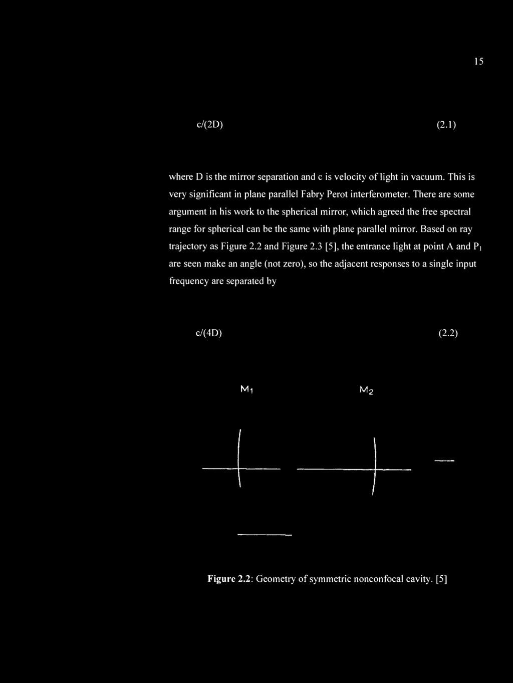
25 Spherical and plane mirror Fabry Perot interferometer The foremost element is the mirror itself because in Fabry Perot interferometer device, it can be classified into two types of mirrors; plane'and spherical mirror that so significant in producing multiple reflection. There gives much interest in application of Fabry Perot interferometer by using spherical mirror rather than plane mirror because it serves several advantages. This was proven by Fork, Herriott and Kogelnik [4] who determined that the spherical mirror interferometers have extraordinarily high resolutions. They recognized that confocal resonators offer high peak transmission than nonconfocal arrangements. However, nonconfocal setups are more lenient in terms of the relatively loose tolerance on the mirror separation and own capability to select various free spectral ranges with a given pair of mirrors but low light gathering intensity of the resonator. In their paper also mentioned about mode matching method which is the method to allow beam to get its path in the system properly by using geometrical optics approach [4], In other hand, it can be described as to match beam parameters between the laser source optical element or beam enlarging system and the interferometer. The whole of the explanation can be illustrated as Figure 2.1 [4] below. Bioconvex lens or matching lens takes part in important role so that an adequate radius of beam after laser source as well as collected beam by interferometer device can be achieved.


26

27


28

29


30


31


32
33


34


35


36
37 REFERENCES 1. Frank L. P., S. J., Leno S. P. and Leno M. P. Introduction to Optics. 3 rd ed. Sansome St., S. F.: Addison -Wesley Luhs, W. Fabry Perot Resonator. MEOS GmbH Eschbach Fabry, C. and Perot, A. On the Application of Interference Phenomena to the Solution of Various Problems of Spectroscopy and Metrology. Astrophysics Journal : Fork, R. L., Herriott, D. R. and Kogelnik, H. A Scanning Spherical Mirror Interferometer for Spectral Analysis of Laser Radiation. Applied Optics (12): Johnson, J. R. A High Resolution Scanning Confocal Interferometer. Applied Optics (6): Abu-Safia, H., Al-Tahtamouni, R., Abu-Aljarayesh, I. and Yusuf, N. A. Transmission of a Gaussian Beam through a Fabry Perot Interferometer. Applied Optics (18): Hercher, M. The Spherical Mirror Fabry Perot Interferometer. Applied Optics (5):
38 64 8. Wilksch, P. A. Instrument function of the Fabry-Perot spectrometer. Applied Optics (10): Davis, G. R., Furniss, I., Towlson, W. A., Ade, P. A. R., Emery, R. J., Glencross, W. M., Naylor, D. A., Patrick, T. J., Sidey, R. C. and Swinyard, B. M. Design and Performance of Cryogenic, Scanning Fabry Perot Interferometers for the Long Wavelength Spectrometer on the Infrared Space Observatory. Applied Optics (1): Allen, L. and Jones, D. G. C. The Helium Neon laser. Advances in Physics (56): Allen, L. and Jones, D. G. C. Principles of Gas Lasers. American journal of Physics (7): Kasap, S. O. Optoelectronics and Photonics: Principle and Practices. Upper Saddle River, N. J.: Prentice-Hall Britun, N., Gaillard, M., Oh, S. G. and Han, J. G. Fabry-Perot Interferometer for Magnetron Plasma Temperature Diagnostics. Journal Physics D: Applied Physics : Kerner, K., Rochester, S. M Yashchuk, V. V. and Budker, D. Variable Free Spectral Range Spherical Mirror Fabry-Perot Interferometer. Nuclear Science Division, Lawrence Berkeley National Laboratory, Berkeley
Some Topics in Optics
 Some Topics in Optics The HeNe LASER The index of refraction and dispersion Interference The Michelson Interferometer Diffraction Wavemeter Fabry-Pérot Etalon and Interferometer The Helium Neon LASER A
Where are the Fringes? (in a real system) Div. of Amplitude - Wedged Plates. Fringe Localisation Double Slit. Fringe Localisation Grating
 Div. of Amplitude - Wedged Plates. Fringe Localisation Double Slit. Fringe Localisation Grating") Where are the Fringes? (in a real system) Fringe Localisation Double Slit spatial modulation transverse fringes? everywhere or well localised? affected by source properties: coherence, extension Plane
Where are the Fringes? (in a real system) Fringe Localisation Double Slit spatial modulation transverse fringes? everywhere or well localised? affected by source properties: coherence, extension Plane
PRINCIPLES OF PHYSICAL OPTICS
 PRINCIPLES OF PHYSICAL OPTICS C. A. Bennett University of North Carolina At Asheville WILEY- INTERSCIENCE A JOHN WILEY & SONS, INC., PUBLICATION CONTENTS Preface 1 The Physics of Waves 1 1.1 Introduction
Interferometers. PART 1: Michelson Interferometer The Michelson interferometer is one of the most useful of all optical instru
 Interferometers EP421 Lab Interferometers Introduction: Interferometers are the key to accurate distance measurement using optics. Historically, when mechanical measurements dominated, interferometers
Experiment 3 1. The Michelson Interferometer and the He- Ne Laser Physics 2150 Experiment No. 3 University of Colorado
 Experiment 3 1 Introduction The Michelson Interferometer and the He- Ne Laser Physics 2150 Experiment No. 3 University of Colorado The Michelson interferometer is one example of an optical interferometer.
Spectroscopic Instruments
 Spectroscopic Instruments 95 Spectroscopic Instruments by division of amplitude Mach-Zehnder (division of amplitude) Michelson Fringe localisation LIGO Fabry-Perot (FPI) Multi-layer coatings 96 Mach-Zehnder
A novel scheme for measuring the relative phase difference between S and P polarization in optically denser medium
 A novel scheme for measuring the relative phase difference between S and P polarization in optically denser medium Abstract Yu Peng School of Physics, Beijing Institute of Technology, Beijing, 100081,
Michelson Interferometer
 Michelson Interferometer Objective Determination of the wave length of the light of the helium-neon laser by means of Michelson interferometer subsectionprinciple and Task Light is made to produce interference
Astronomy 203 practice final examination
 Astronomy 203 practice final examination Fall 1999 If this were a real, in-class examination, you would be reminded here of the exam rules, which are as follows: You may consult only one page of formulas
JRE Group of Institutions ASSIGNMENT # 1 Special Theory of Relativity
 ASSIGNMENT # 1 Special Theory of Relativity 1. What was the objective of conducting the Michelson-Morley experiment? Describe the experiment. How is the negative result of the experiment interpreted? 2.
The Michelson Interferometer and the He-Ne Laser Physics 2150 Experiment No. 3 University of Colorado
 Experiment 3 1 Introduction The Michelson Interferometer and the He-Ne Laser Physics 2150 Experiment No. 3 University of Colorado In the experiment, two different types of measurements will be made with
Edward S. Rogers Sr. Department of Electrical and Computer Engineering. ECE318S Fundamentals of Optics. Final Exam. April 16, 2007.
 Edward S. Rogers Sr. Department of Electrical and Computer Engineering ECE318S Fundamentals of Optics Final Exam April 16, 2007 Exam Type: D (Close-book + two double-sided aid sheets + a non-programmable
Fabry-Perot Interferometers
 Fabry-Perot Interferometers Astronomy 6525 Literature: C.R. Kitchin, Astrophysical Techniques Born & Wolf, Principles of Optics Theory: 1 Fabry-Perots are best thought of as resonant cavities formed between
MODERN OPTICS. P47 Optics: Unit 9
 MODERN OPTICS P47 Optics: Unit 9 Course Outline Unit 1: Electromagnetic Waves Unit 2: Interaction with Matter Unit 3: Geometric Optics Unit 4: Superposition of Waves Unit 5: Polarization Unit 6: Interference
The science of light. P. Ewart
 The science of light P. Ewart Oxford Physics: Second Year, Optics Parallel reflecting surfaces t images source Extended source path difference xcos 2t=x Fringes localized at infinity Circular fringe constant
34. Even more Interference Effects
 34. Even more Interference Effects The Fabry-Perot interferometer Thin-film interference Anti-reflection coatings Single- and multi-layer Advanced topic: Photonic crystals Natural and artificial periodic
Laser Optics-II. ME 677: Laser Material Processing Instructor: Ramesh Singh 1
 Laser Optics-II 1 Outline Absorption Modes Irradiance Reflectivity/Absorption Absorption coefficient will vary with the same effects as the reflectivity For opaque materials: reflectivity = 1 - absorptivity
For more sample papers visit :
 PHYSICS (THEORY) (Three hours) For more sample papers visit : www.4ono.com Answer all questions in Part I and six questions from Part II, choosing two questions from each of the Sections A, B and C. All
TITLE: Interferometry: The Michelson Interferometer
 TITLE: Interferometry: The Michelson Interferometer Contributed by: Yolanda Flores Baboquivari High School Summary: The lesson begins with a demonstration introducing students to interference fringes formed
Optics, Light and Lasers
 Dieter Meschede Optics, Light and Lasers The Practical Approach to Modern Aspects of Photonics and Laser Physics Second, Revised and Enlarged Edition BICENTENNIAL.... n 4 '':- t' 1 8 0 7 $W1LEY 2007 tri
Atomic and nuclear physics
 Atomic and nuclear physics Atomic shell Normal Zeeman effect LEYBOLD Physics Leaflets Observing the normal Zeeman effect in transverse and longitudinal configuration Spectroscopy with a Fabry-Perot etalon
The Michelson Interferometer
 Experiment #33 The Michelson Interferometer References 1. Your first year physics textbook. 2. Hecht, Optics, Addison Wesley - Chapter 9 in the 4th Ed. (2001). 3. Jenkins and White, Fundamentals of Optics
3.1 The Plane Mirror Resonator 3.2 The Spherical Mirror Resonator 3.3 Gaussian modes and resonance frequencies 3.4 The Unstable Resonator
 Quantum Electronics Laser Physics Chapter 3 The Optical Resonator 3.1 The Plane Mirror Resonator 3. The Spherical Mirror Resonator 3.3 Gaussian modes and resonance frequencies 3.4 The Unstable Resonator
Q2 (Michelson) - solution here
 - solution here") The TA is still preparing the solutions for PS#4 and they should be ready on Sunday or early Monday. Meanwhile here are some materials and comments from me. -RSM Q (Michelson) - solution here some notes/comments
The TA is still preparing the solutions for PS#4 and they should be ready on Sunday or early Monday. Meanwhile here are some materials and comments from me. -RSM Q (Michelson) - solution here some notes/comments
Optics, Optoelectronics and Photonics
 Optics, Optoelectronics and Photonics Engineering Principles and Applications Alan Billings Emeritus Professor, University of Western Australia New York London Toronto Sydney Tokyo Singapore v Contents
Chapter 2 Basic Optics
 Chapter Basic Optics.1 Introduction In this chapter we will discuss the basic concepts associated with polarization, diffraction, and interference of a light wave. The concepts developed in this chapter
gives rise to multitude of four-wave-mixing phenomena which are of great
 Module 4 : Third order nonlinear optical processes Lecture 26 : Third-order nonlinearity measurement techniques: Z-Scan Objectives In this lecture you will learn the following Theory of Z-scan technique
Polarized Light. Nikki Truss. Abstract:
 Polarized Light Nikki Truss 9369481 Abstract: In this experiment, the properties of linearly polarised light were examined. Malus Law was verified using the apparatus shown in Fig. 1. Reflectance of s-polarised
PHYSICS PAPER 1 (THEORY)
") PHYSICS PAPER 1 (THEORY) (Three hours) (Candidates are allowed additional 15 minutes for only reading the paper. They must NOT start writing during this time.) ---------------------------------------------------------------------------------------------------------------------
PHYSICS PAPER 1 (THEORY) (Three hours) (Candidates are allowed additional 15 minutes for only reading the paper. They must NOT start writing during this time.) ---------------------------------------------------------------------------------------------------------------------
An Overview of Advanced LIGO Interferometry
 An Overview of Advanced LIGO Interferometry Luca Matone Columbia Experimental Gravity group (GECo) Jul 16-20, 2012 LIGO-G1200743 Day Topic References 1 2 3 4 5 Gravitational Waves, Michelson IFO, Fabry-Perot
Measurements in Optics for Civil Engineers
 Measurements in Optics for Civil Engineers I. FOCAL LENGTH OF LENSES The behavior of simplest optical devices can be described by the method of geometrical optics. For convex or converging and concave
Experiment O-2. The Michelson Interferometer
 Experiment O-2 The Michelson Interferometer The Michelson interferometer is one of the best known and historically important interferometers. It is a very accurate length-measuring device and has been
PHY410 Optics Exam #3
 PHY410 Optics Exam #3 NAME: 1 2 Multiple Choice Section - 5 pts each 1. A continuous He-Ne laser beam (632.8 nm) is chopped, using a spinning aperture, into 500 nanosecond pulses. Compute the resultant
Edward S. Rogers Sr. Department of Electrical and Computer Engineering. ECE426F Optical Engineering. Final Exam. Dec. 17, 2003.
 Edward S. Rogers Sr. Department of Electrical and Computer Engineering ECE426F Optical Engineering Final Exam Dec. 17, 2003 Exam Type: D (Close-book + one 2-sided aid sheet + a non-programmable calculator)
Introduction to FT-IR Spectroscopy
 Introduction to FT-IR Spectroscopy An FT-IR Spectrometer is an instrument which acquires broadband NIR to FIR spectra. Unlike a dispersive instrument, i.e. grating monochromator or spectrograph, an FT-IR
Light as a Transverse Wave.
 Waves and Superposition (Keating Chapter 21) The ray model for light (i.e. light travels in straight lines) can be used to explain a lot of phenomena (like basic object and image formation and even aberrations)
PS210 - Optical Techniques. Section VI
 PS210 - Optical Techniques Section VI Section I Light as Waves, Rays and Photons Section II Geometrical Optics & Optical Instrumentation Section III Periodic and Non-Periodic (Aperiodic) Waves Section
The Plasma Phase. Chapter 1. An experiment - measure and understand transport processes in a plasma. Chapter 2. An introduction to plasma physics
 The Plasma Phase Chapter 1. An experiment - measure and understand transport processes in a plasma Three important vugraphs What we have just talked about The diagnostics Chapter 2. An introduction to
OPTI510R: Photonics. Khanh Kieu College of Optical Sciences, University of Arizona Meinel building R.626
 OPTI510R: Photonics Khanh Kieu College of Optical Sciences, University of Arizona kkieu@optics.arizona.edu Meinel building R.626 Important announcements Homework #1 is due. Homework #2 is assigned, due
Michelson Interferometer. crucial role in Einstein s development of the Special Theory of Relativity.
 Michelson Interferometer The interferometer Michelson experiment Interferometer of Michelson and Morley played 0 a crucial role in Einstein s development of the Special Theory of Relativity. Michelson
Group Velocity and Phase Velocity
 Group Velocity and Phase Velocity Tuesday, 10/31/2006 Physics 158 Peter Beyersdorf Document info 14. 1 Class Outline Meanings of wave velocity Group Velocity Phase Velocity Fourier Analysis Spectral density
THE ZEEMAN EFFECT v3 R. A. Schumacher, May 2017 B. B. Luokkala, January 2001
 THE ZEEMAN EFFECT v3 R. A. Schumacher, May 2017 B. B. Luokkala, January 2001 I. INTRODUCTION The goal of this experiment is to measure the Bohr magneton using the normal Zeeman effect of the 643.8 nm (red)
PH 222-3A Spring 2010
 PH -3A Spring 010 Interference Lecture 6-7 Chapter 35 (Halliday/Resnick/Walker, Fundamentals of Physics 8 th edition) 1 Chapter 35 Interference The concept of optical interference is critical to understanding
Modern optics Lasers
 Chapter 13 Phys 322 Lecture 36 Modern optics Lasers Reminder: Please complete the online course evaluation Last lecture: Review discussion (no quiz) LASER = Light Amplification by Stimulated Emission of
EFFECT OF NOZZLE ANGLE ON JET IMPINGEMENT COOLING SYSTEM KHAIDER BIN ABU BAKAR
 EFFECT OF NOZZLE ANGLE ON JET IMPINGEMENT COOLING SYSTEM KHAIDER BIN ABU BAKAR Report submitted in fulfilment of the requirements for the award of the degree of Bachelor of Mechanical Engineering Faculty
 Name : Roll No. :.. Invigilator s Signature :.. CS/B.Tech/SEM-2/PH-201/2010 2010 ENGINEERING PHYSICS Time Allotted : 3 Hours Full Marks : 70 The figures in the margin indicate full marks. Candidates are
1. Waves and Particles 2. Interference of Waves 3. Wave Nature of Light
 1. Waves and Particles 2. Interference of Waves 3. Wave Nature of Light 1. Double-Slit Eperiment reading: Chapter 22 2. Single-Slit Diffraction reading: Chapter 22 3. Diffraction Grating reading: Chapter
THE INDIAN COMMUNITY SCHOOL, KUWAIT SECOND SEMESTER EXAMINATION PHYSICS (Theory)
") CLASS:XII Marks : 70 General Instructions: THE INDIAN COMMUNITY SCHOOL, KUWAIT SECOND SEMESTER EXAMINATION 2016-17 PHYSICS (Theory) Time : Hrs (i) (ii) (iii) (iv) (v) All questions are compulsory. This
CLASS:XII Marks : 70 General Instructions: THE INDIAN COMMUNITY SCHOOL, KUWAIT SECOND SEMESTER EXAMINATION 2016-17 PHYSICS (Theory) Time : Hrs (i) (ii) (iii) (iv) (v) All questions are compulsory. This
Physics of Light and Optics
 Physics of Light and Optics Justin Peatross and Harold Stokes Brigham Young University Department of Physics and Astronomy All Publication Rights Reserved (2001) Revised April 2002 This project is supported
Roll No. :... Invigilator's Signature :.. CS/B.TECH(N)/SEM-1/PH-101/ PHYSICS - I. Time Allotted : 3 Hours Full Marks : 70
/SEM-1/PH-101/ PHYSICS - I. Time Allotted : 3 Hours Full Marks : 70") Name : Roll No. :.... Invigilator's Signature :.. CS/B.TECH(N)/SEM-1/PH-101/2012-13 2012 PHYSICS - I Time Allotted : 3 Hours Full Marks : 70 The figures in the margin indicate full marks. Candidates are
Name : Roll No. :.... Invigilator's Signature :.. CS/B.TECH(N)/SEM-1/PH-101/2012-13 2012 PHYSICS - I Time Allotted : 3 Hours Full Marks : 70 The figures in the margin indicate full marks. Candidates are
1. Consider the biconvex thick lens shown in the figure below, made from transparent material with index n and thickness L.
 Optical Science and Engineering 2013 Advanced Optics Exam Answer all questions. Begin each question on a new blank page. Put your banner ID at the top of each page. Please staple all pages for each individual
The Zeeman Effect in Mercury Vapor and the Determination e/m by Fabry-Perot Interferometry
 The Zeeman Effect in Mercury Vapor and the Determination e/m by Fabry-Perot Interferometry Edwin Ng MIT Department of Physics (Dated: March 17, 2012) We analyze the Zeeman fine structure of mercury vapor
Abstract... I. Acknowledgements... III. Table of Content... V. List of Tables... VIII. List of Figures... IX
 Abstract... I Acknowledgements... III Table of Content... V List of Tables... VIII List of Figures... IX Chapter One IR-VUV Photoionization Spectroscopy 1.1 Introduction... 1 1.2 Vacuum-Ultraviolet-Ionization
and the radiation from source 2 has the form. The vector r points from the origin to the point P. What will the net electric field be at point P?
 Physics 3 Interference and Interferometry Page 1 of 6 Interference Imagine that we have two or more waves that interact at a single point. At that point, we are concerned with the interaction of those
Spectroscopy. Practical Handbook of. J. W. Robinson, Ph.D., D.Sc, F.R.C.S. Department of Chemistry Louisiana State University Baton Rouge, Louisiana
 Practical Handbook of Spectroscopy Edited by J. W. Robinson, Ph.D., D.Sc, F.R.C.S. Department of Chemistry Louisiana State University Baton Rouge, Louisiana CRC Press Boca Raton Ann Arbor Boston TABLE
CBSE PHYSICS QUESTION PAPER (2005)
") CBSE PHYSICS QUESTION PAPER (2005) (i) (ii) All questions are compulsory. There are 30 questions in total. Questions 1 to 8 carry one mark each, Questions 9 to 18 carry two marks each, Question 19 to 27
CBSE PHYSICS QUESTION PAPER (2005) (i) (ii) All questions are compulsory. There are 30 questions in total. Questions 1 to 8 carry one mark each, Questions 9 to 18 carry two marks each, Question 19 to 27
Einstein Classes, Unit No. 102, 103, Vardhman Ring Road Plaza, Vikas Puri Extn., Outer Ring Road New Delhi , Ph. : ,
 1 O P T I C S 1. Define resolving power of a telescope & microscope and give the expression for its resolving power. 2. Explain briefly the formation of mirage in deserts. 3. The radii of curvature of
Model Answer (Paper code: AR-7112) M. Sc. (Physics) IV Semester Paper I: Laser Physics and Spectroscopy
 M. Sc. (Physics) IV Semester Paper I: Laser Physics and Spectroscopy") Model Answer (Paper code: AR-7112) M. Sc. (Physics) IV Semester Paper I: Laser Physics and Spectroscopy Section I Q1. Answer (i) (b) (ii) (d) (iii) (c) (iv) (c) (v) (a) (vi) (b) (vii) (b) (viii) (a) (ix)
Model Answer (Paper code: AR-7112) M. Sc. (Physics) IV Semester Paper I: Laser Physics and Spectroscopy Section I Q1. Answer (i) (b) (ii) (d) (iii) (c) (iv) (c) (v) (a) (vi) (b) (vii) (b) (viii) (a) (ix)
SOFT X-RAYS AND EXTREME ULTRAVIOLET RADIATION
 SOFT X-RAYS AND EXTREME ULTRAVIOLET RADIATION Principles and Applications DAVID ATTWOOD UNIVERSITY OF CALIFORNIA, BERKELEY AND LAWRENCE BERKELEY NATIONAL LABORATORY CAMBRIDGE UNIVERSITY PRESS Contents
Name :. Roll No. :... Invigilator s Signature :.. CS/B. Tech (New)/SEM-1/PH-101/ PHYSICS-I
/SEM-1/PH-101/ PHYSICS-I") Name :. Roll No. :..... Invigilator s Signature :.. CS/B. Tech (New)/SEM-1/PH-101/2011-12 2011 PHYSICS-I Time Allotted : 3 Hours Full Marks : 70 The figures in the margin indicate full marks. Candidates
Name :. Roll No. :..... Invigilator s Signature :.. CS/B. Tech (New)/SEM-1/PH-101/2011-12 2011 PHYSICS-I Time Allotted : 3 Hours Full Marks : 70 The figures in the margin indicate full marks. Candidates
A Fabry-Perot Interferometer System for high-speed velocity measurement. Lun K. Cheng, A.J.A. Bruinsma, W.C. Prinse* and C.
 A Fabry-Perot Interferometer System for high-speed velocity measurement Lun K. Cheng, A.J.A. Bruinsma, W.C. Prinse* and C. Smorenburg TNO Inst. of Appi. Phys., 2600 AD Deift, The Netherlands *TNO Prins
3rd Year Mini Project - The Helium Neon LASER
 3rd Year Mini Project - The Helium Neon LASER Kylie J MacFarquharson May 11, 2018 Abstract In this experiment we built a large He-Ne LASER with an open cavity. We then investigated various properties of
Light as Wave Motion p. 1 Huygens' Ideas p. 2 Newton's Ideas p. 8 Complex Numbers p. 10 Simple Harmonic Motion p. 11 Polarized Waves in a Stretched
 Introduction p. xvii Light as Wave Motion p. 1 Huygens' Ideas p. 2 Newton's Ideas p. 8 Complex Numbers p. 10 Simple Harmonic Motion p. 11 Polarized Waves in a Stretched String p. 16 Velocities of Mechanical
PROCEEDINGS OF SPIE. Optical phase measurement emphasized
 PROCEEDINGS OF SPIE SPIEDigitalLibrary.org/conference-proceedings-of-spie Optical phase measurement emphasized Ertan Salik Ertan Salik, "Optical phase measurement emphasized," Proc. SPIE 9666, 11th Education
Metrology and Sensing
 Metrology and Sensing Lecture 5: Interferometry I 08--6 Herbert Gross Winter term 08 www.iap.uni-jena.de Schedule Optical Metrology and Sensing 08 No Date Subject Detailed Content 6.0. Introduction Introduction,
KENDRIYA VIDYALAYA SANGATHAN, HYDERABAD REGION
 KENDRIYA VIDYALAYA SANGATHAN, HYDERABAD REGION SAMPLE PAPER 03 (2017-18) SUBJECT: PHYSICS (043) BLUE PRINT : CLASS XII UNIT VSA (1 mark) SA - I (2 marks) SA II (3 marks) VBQ (4 marks) LA (5 marks) Total
Physical Optics 2018 Dr. Muwafaq Fadhil Al-Mishlab Third lecture [ Huygens Principle, Interference of light]
![Physical Optics 2018 Dr. Muwafaq Fadhil Al-Mishlab Third lecture [ Huygens Principle, Interference of light]](/thumbs/96/128206880.jpg "Physical Optics 2018 Dr. Muwafaq Fadhil Al-Mishlab Third lecture [ Huygens Principle, Interference of light]") Physical Optics 2018 Dr. Muwafaq Fadhil Al-Mishlab Third lecture [ Huygens Principle, Interference of light] 1. Huygens principle Long before people understood the electromagnetic character of light, Christian
Physical Optics 2018 Dr. Muwafaq Fadhil Al-Mishlab Third lecture [ Huygens Principle, Interference of light] 1. Huygens principle Long before people understood the electromagnetic character of light, Christian
Chemistry Instrumental Analysis Lecture 15. Chem 4631
 Chemistry 4631 Instrumental Analysis Lecture 15 IR Instruments Types of Instrumentation Dispersive Spectrophotometers (gratings) Fourier transform spectrometers (interferometer) Single beam Double beam
Metrology and Sensing
 Metrology and Sensing Lecture 5: Interferometry I 06--09 Herbert Gross Winter term 06 www.iap.uni-jena.de Preliminary Schedule No Date Subject Detailed Content 8.0. Introduction Introduction, optical measurements,
Electricity & Optics
 Physics 24100 Electricity & Optics Lecture 26 Chapter 33 sec. 1-4 Fall 2017 Semester Professor Koltick Interference of Light Interference phenomena are a consequence of the wave-like nature of light Electric
Internal magnetic field measurement in tokamak plasmas using a Zeeman polarimeter
 PRAMANA cfl Indian Academy of Sciences Vol. 55, Nos 5 & 6 journal of Nov. & Dec. 2000 physics pp. 751 756 Internal magnetic field measurement in tokamak plasmas using a Zeeman polarimeter M JAGADEESHWARI
Modeling of the fringe shift in multiple beam interference for glass fibers
 PRAMANA c Indian Academy of Sciences Vol. 70, No. 4 journal of April 2008 physics pp. 643 648 Modeling of the fringe shift in multiple beam interference for glass fibers A M HAMED 1 Physics Department,
Science Curriculum Matrix
 Science Curriculum Matrix Physics Version 1.0 beta June 2, 2008 This curriculum (core matrix) document will eventually become part of the Science Curriculum Matrix. We envision the Science Curriculum Matrix
Class XII Physics (Theory)
") DATE : 0/03/209 SET-3 Code No. //3 Regd. Office : Aakash Tower, 8, Pusa Road, New Delhi-000. Ph.: 0-4762346 Class XII Physics (Theory) Time : 3 Hrs. Max. Marks : 70 (CBSE 209) GENERAL INSTRUCTIONS :. All
DATE : 0/03/209 SET-3 Code No. //3 Regd. Office : Aakash Tower, 8, Pusa Road, New Delhi-000. Ph.: 0-4762346 Class XII Physics (Theory) Time : 3 Hrs. Max. Marks : 70 (CBSE 209) GENERAL INSTRUCTIONS :. All
Polarization of Light and Birefringence of Materials
 Polarization of Light and Birefringence of Materials Ajit Balagopal (Team Members Karunanand Ogirala, Hui Shen) ECE 614- PHOTONIC INFORMATION PROCESSING LABORATORY Abstract-- In this project, we study
Interference- Michelson Interferometer. Interference lecture by Dr. T.Vishwam
 Interference- Michelson Interferometer Interference lecture by Dr. T.Vishwam * Measurement of the coherence length of a spectral line * Measurement of thickness of thin transparent flakes * Measurement
Course Secretary: Christine Berber O3.095, phone x-6351,
 IMPRS: Ultrafast Source Technologies Franz X. Kärtner (Umit Demirbas) & Thorsten Uphues, Bldg. 99, O3.097 & Room 6/3 Email & phone: franz.kaertner@cfel.de, 040 8998 6350 thorsten.uphues@cfel.de, 040 8998
A few Experimental methods for optical spectroscopy Classical methods Modern methods. Remember class #1 Generating fast LASER pulses
 A few Experimental methods for optical spectroscopy Classical methods Modern methods Shorter class Remember class #1 Generating fast LASER pulses, 2017 Uwe Burghaus, Fargo, ND, USA W. Demtröder, Laser
POLARIZATION OF LIGHT
 POLARIZATION OF LIGHT OVERALL GOALS The Polarization of Light lab strongly emphasizes connecting mathematical formalism with measurable results. It is not your job to understand every aspect of the theory,
B.Tech. First Semester Examination Physics-1 (PHY-101F)
") B.Tech. First Semester Examination Physics-1 (PHY-101F) Note : Attempt FIVE questions in all taking least two questions from each Part. All questions carry equal marks Part-A Q. 1. (a) What are Newton's
B.Tech. First Semester Examination Physics-1 (PHY-101F) Note : Attempt FIVE questions in all taking least two questions from each Part. All questions carry equal marks Part-A Q. 1. (a) What are Newton's
Lab 2: Mach Zender Interferometer Overview
 Lab : Mach Zender Interferometer Overview Goals:. Study factors that govern the interference between two light waves with identical amplitudes and frequencies. Relative phase. Relative polarization. Learn
Introduction. Procedure. In this experiment, you'll use the interferometer to EQUIPMENT NEEDED: Lens 18mm FL. Component holder.
 12-7137A Precision Interferometer Experiment 1: Introduction to Interferometry EQUIPMENT NEEDED: Basic Interferometer (OS-9255A) Laser (OS-9171) Laser Alignment Bench (OS-9172) Interferometer Accessories
Chapter 35. Interference
 Chapter 35 Interference The concept of optical interference is critical to understanding many natural phenomena, ranging from color shifting in butterfly wings to intensity patterns formed by small apertures.
PHYSICS 370 OPTICS. Instructor: Dr. Fred Otto Phone:
 PHYSICS 370 OPTICS Instructor: Dr. Fred Otto Phone: 457-5854 Office: Pasteur 144 E-mail: fotto@winona.edu Text: F.L. Pedrotti, L.S. Pedrotti, and L.M. Pedrotti, Introduction to Optics, 3 rd Ed., 2000,
P123 University of Rochester NAME S. Manly Spring 2013
 Final Exam (May 7, 2013) Please read the problems carefully and answer them in the space provided. Write on the back of the page, if necessary. Show all your work. Partial credit will be given unless specified
Calculating Thin Film Stack Properties
 Lecture 5: Thin Films Outline 1 Thin Films 2 Calculating Thin Film Stack Properties 3 Fabry-Perot Tunable Filter 4 Anti-Reflection Coatings 5 Interference Filters Christoph U. Keller, Leiden University,
The Anomalous Zeeman Splitting of the Sodium 3P States
 Advanced Optics Laboratory The Anomalous Zeeman Splitting of the Sodium 3P States David Galey Lindsay Stanceu Prasenjit Bose April 5, 010 Objectives Calibrate Fabry-Perot interferometer Determine the Zeeman
S. Blair September 27,
 S. Blair September 7, 010 54 4.3. Optical Resonators With Spherical Mirrors Laser resonators have the same characteristics as Fabry-Perot etalons. A laser resonator supports longitudinal modes of a discrete
Chapter 28 Atomic Physics
 Chapter 28 Atomic Physics GOALS After you have mastered the contents of this chapter, you will be able to achieve the following goals: Definitions Define each of the following terms and use it in an operational
Calculating Thin Film Stack Properties. Polarization Properties of Thin Films
 Lecture 6: Thin Films Outline 1 Thin Films 2 Calculating Thin Film Stack Properties 3 Polarization Properties of Thin Films 4 Anti-Reflection Coatings 5 Interference Filters Christoph U. Keller, Utrecht
Design and Development of a Smartphone Based Visible Spectrophotometer for Analytical Applications
 Design and Development of a Smartphone Based Visible Spectrophotometer for Analytical Applications Bedanta Kr. Deka, D. Thakuria, H. Bora and S. Banerjee # Department of Physicis, B. Borooah College, Ulubari,
5. You may use the following values of physical constants wherever necessary. Class XII Physics (042) Sample Question Paper
 Sample Question Paper") Class XII Physics (04) Sample Question Paper 018-19 Time allowed: hours. Max. Marks: 70 General Instructions: 1. All questions are compulsory. There are 7 questions in all.. This question paper has four
Class XII Physics (04) Sample Question Paper 018-19 Time allowed: hours. Max. Marks: 70 General Instructions: 1. All questions are compulsory. There are 7 questions in all.. This question paper has four
DELHI PUBLIC SCHOOL, BAHADURGARH Sample Paper 1 PHYSICS CLASS-XII Date- Duration:3hr
 SET: 1 General Instructions:- DELHI PUBLIC SCHOOL, BAHADURGARH Sample Paper 1 PHYSICS CLASS-XII Date- Duration:3hr All questions are compulsory. There are 30 questions in total. Questions 1 to 8 carry
Stimulated Emission Devices: LASERS
 Stimulated Emission Devices: LASERS 1. Stimulated Emission and Photon Amplification E 2 E 2 E 2 hυ hυ hυ In hυ Out hυ E 1 E 1 E 1 (a) Absorption (b) Spontaneous emission (c) Stimulated emission The Principle
Lecture 11: Doppler wind lidar
 Lecture 11: Doppler wind lidar Why do we study winds? v Winds are the most important variable studying dynamics and transport in the atmosphere. v Wind measurements are critical to improvement of numerical
Engineering Physics 1 Prof. G.D. Varma Department of Physics Indian Institute of Technology-Roorkee
 Engineering Physics 1 Prof. G.D. Varma Department of Physics Indian Institute of Technology-Roorkee Module-03 Lecture-01 Interference of Light Part 01 Myself, Dr. JD Varma, Associate Professor in Department
KENDRIYA VIDYALAYA SANGATHAN, HYDERABAD REGION
 KENDRIYA VIDYALAYA SANGATHAN, HYDERABAD REGION SAMPLE PAPER 04 (2017-18) SUBJECT: PHYSICS (043) BLUE PRINT : CLASS XII UNIT VSA (1 mark) SA - I (2 marks) SA II (3 marks) VBQ (4 marks) LA (5 marks) Total
Zeeman Effect. Alex Povilus Physics 441- Fall 2003 December 20, 2003
 Zeeman Effect Alex Povilus Physics 441- Fall 2003 December 20, 2003 Abstract The Zeeman Effect is observed by application of a strong magnetic field to a mercury vapor cell and exciting transitions by
Chapter 1. Optical Interferometry. Introduction
 Chapter 1 Optical Interferometry Experiment objectives: Assemble and align Michelson and Fabry-Perot interferometers, calibrate them using a laser of known wavelength, and then use them characterize the
Homework 1. Property LASER Incandescent Bulb
 Homework 1 Solution: a) LASER light is spectrally pure, single wavelength, and they are coherent, i.e. all the photons are in phase. As a result, the beam of a laser light tends to stay as beam, and not