DOUBLE ARM JUGGLING SYSTEM Progress Presentation ECSE-4962 Control Systems Design
|
|
|
- Naomi Townsend
- 5 years ago
- Views:
Transcription

1 DOUBLE ARM JUGGLING SYSTEM Progress Presentation ECSE-4962 Control Systems Design Group Members: John Kua Trinell Ball Linda Rivera
2 Introduction Where are we? Bulk of Design and Build Complete Testing and Tuning Phase Preliminary Results Physical Design Model Development Control Systems Development Camera Development


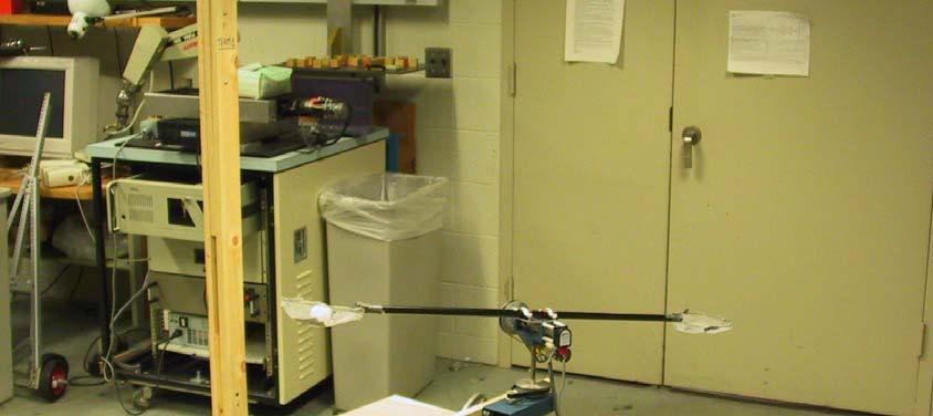
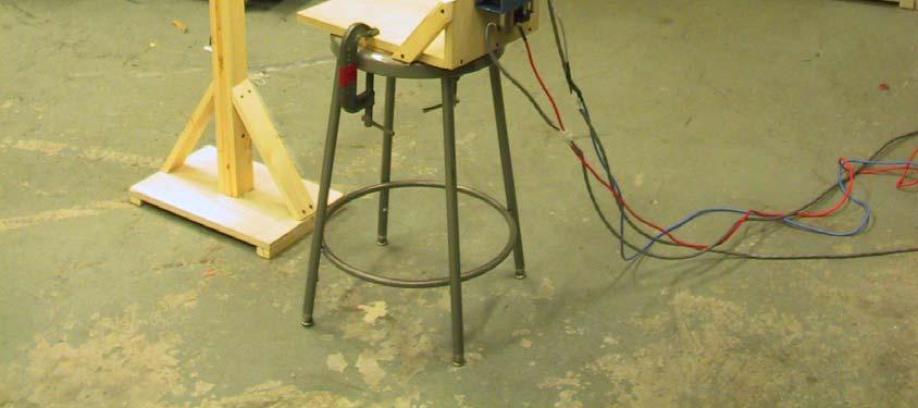
3 Physical Design Additions: Camera Mounting Overall System Mounting Other physical modifications Shaft Mounting Cable extensions Challenges: Net Design Material Building Possible solutions: Foil wrapping current nets Replacing nets Camera Mounting Shaft Mounting System Mounting
4 Model Development Lagrange-Euler Model τ = M ( θ ) θ + C( θ, θ ) θ + F( θ ) + G( θ ) Single Joint τ m = J a + n J m + nj L θ s + F v θ s + F c sign θ ) ( s
5 Simulink Model - Nonlinear MATLAB Function -K- tau theta theta Step DAC Output Saturation DAC to Current Motor Torque Constant Single Joint Physics Scope 1 tau f(u) Mass^-1 Accel 1 s Integrator Velocity Motor Speed Saturation 1 s Integrator1 Position 1 theta Viscous Friction Scope1 Scope3 -K- -K- Sign Coulomb Friction
6 DAC to Current Model Digital to Analog Conversion Tested voltage over a range Fit curve to data found slope, offset Voltage to Current Conversion Adjusted gain to approximately 0.1A/V Tested current over a range Applied load to system for accurate measurement I tilt = e- 005 x I pan = e x
7 Friction Identification Identify Viscous and Coulomb Friction Apply constant torque and measure steady state velocity Automate with LabVIEW Process data with MATLAB 25 Velocity vs. Time - Tilt 4000 Digital Output vs. Steady State Velocity - Tilt Digital Output Velocity (rad/s) Velocity (rad/s) Shaft Torque vs. Steady State Velocity - Tilt Time (s) Shaft Torque (N*m) Velocity (rad/s)
8 Other Parameters Inertia/Mass Calculated with SolidWorks Shaft Spring Constant Possible cause of oscillations Experimentally measured Found to be very stiff - k=4600n/m
9 Model Linearization Discard Coulomb Friction State Space Equations x1 = θ, x2 = θ F x x + 2 v = 2 J eff y = x 1 Transfer Function Y ( s) R( s) = x 1 = x 2 s 2 + x θ = θ 1, x = 2 u J eff s
10 Model Verification Compare Friction ID results to simulated Friction ID Velocity vs. Time - Tilt Velocity (rad/s) Time (s) Compare simulated controlled output to implemented output Potentially apply chirp ID methods
11 Velocity Estimation Finite difference method 10ms Minimum velocity of rad/sec Maximum motor speed of 21 rad/sec Designed peak velocity of 15 rad/sec Overflow problem Seeing large velocity pulse in data Limited position to +/- 180 degrees Corrected velocity when over limits (153 rad/sec)
12 Trajectory Calculation Drag force on the ball 2 Projectile Motion of a Ping Pong Ball D = 1 ρ v 2 Trajectory deviates from standard projectile motion equation Differential Equation Iterative vs. Simulink ODE Solver 2 AC d y (meters) x (meters)
13 Control Systems Development Two methods for designing controllers used MATLAB rltool (Pole Placement method) 1. Obtain transfer function 2. Import transfer function to rltool 3. Convert continuous model to discrete model (sampling time 10ms 4. Define design constraints, such as rise time and settling time 5. Place gain constant at the crossings of design constraints 6. Export controller to simulink model of system 7. Run simulation to test PID block MATLAB (simulink) Kp = Proportional Ki = Integral Kd = Derivative
14 Pole Placement Methods 1 Tilt-System Root Locus Tilt Root Locus Design Criteria Closed Loop poles Stable Locate system poles at the intersection of ω n and ς Imag Axis Real Axis ω n = 62.8 rad/s ς =.7
15 0 0 Non-Linear System Step Response To different controllers rltool controller PID controller Overshoot: 28.7% Overshoot: 0% Kp = 800 Ki = 20 Kd = X: 0.23 Y: X: 0.69 Y: X: 0.1 Y: X: 0.1 Y:
16
17


18 Camera Development Vision Module Familiarization: Use of NI Vision Assistant Acquire Preliminary data Carry out a number of tests Image Processing Examples: Projectile motion launch


19 Upward vertical launch Image 9/30 Image 12/30 Processing Challenges: Blurred images of the ball Colored backgrounds similar to ball s color

20 Ball blur

21 Background similar to ball color Possible solutions: Blur Take average of circles Background Create uniform dark background
22 Data Verification: Verify if height prediction data is valid Run new experiment Compare results If results from script seem reasonable Use Overhead camera only If results form script are unreliable Add Additional camera on the side Next Steps: Running Trajectory Prediction Integration of Vision Development with Control System Continue to validate data
23 Summary of Progress Schedule On track, only a few items outstanding Costs 10% overbudget,, 20% under estimates Did not purchase motor, built support structures Plan of Action No deviations New Difficulties

24
Laboratory 11 Control Systems Laboratory ECE3557. State Feedback Controller for Position Control of a Flexible Joint
 Laboratory 11 State Feedback Controller for Position Control of a Flexible Joint 11.1 Objective The objective of this laboratory is to design a full state feedback controller for endpoint position control
State Feedback Controller for Position Control of a Flexible Link
 Laboratory 12 Control Systems Laboratory ECE3557 Laboratory 12 State Feedback Controller for Position Control of a Flexible Link 12.1 Objective The objective of this laboratory is to design a full state
Video 5.1 Vijay Kumar and Ani Hsieh
 Video 5.1 Vijay Kumar and Ani Hsieh Robo3x-1.1 1 The Purpose of Control Input/Stimulus/ Disturbance System or Plant Output/ Response Understand the Black Box Evaluate the Performance Change the Behavior
Manufacturing Equipment Control
 QUESTION 1 An electric drive spindle has the following parameters: J m = 2 1 3 kg m 2, R a = 8 Ω, K t =.5 N m/a, K v =.5 V/(rad/s), K a = 2, J s = 4 1 2 kg m 2, and K s =.3. Ignore electrical dynamics
Rotary Motion Servo Plant: SRV02. Rotary Experiment #11: 1-DOF Torsion. 1-DOF Torsion Position Control using QuaRC. Student Manual
 Rotary Motion Servo Plant: SRV02 Rotary Experiment #11: 1-DOF Torsion 1-DOF Torsion Position Control using QuaRC Student Manual Table of Contents 1. INTRODUCTION...1 2. PREREQUISITES...1 3. OVERVIEW OF
Example: DC Motor Speed Modeling
 Page 1 of 5 Example: DC Motor Speed Modeling Physical setup and system equations Design requirements MATLAB representation and open-loop response Physical setup and system equations A common actuator in
Digital Control Semester Project
 Digital Control Semester Project Part I: Transform-Based Design 1 Introduction For this project you will be designing a digital controller for a system which consists of a DC motor driving a shaft with
Quanser NI-ELVIS Trainer (QNET) Series: QNET Experiment #02: DC Motor Position Control. DC Motor Control Trainer (DCMCT) Student Manual
 Series: QNET Experiment #02: DC Motor Position Control. DC Motor Control Trainer (DCMCT) Student Manual") Quanser NI-ELVIS Trainer (QNET) Series: QNET Experiment #02: DC Motor Position Control DC Motor Control Trainer (DCMCT) Student Manual Table of Contents 1 Laboratory Objectives1 2 References1 3 DCMCT Plant
Quanser NI-ELVIS Trainer (QNET) Series: QNET Experiment #02: DC Motor Position Control DC Motor Control Trainer (DCMCT) Student Manual Table of Contents 1 Laboratory Objectives1 2 References1 3 DCMCT Plant
Chapter 6 - Solved Problems
 Chapter 6 - Solved Problems Solved Problem 6.. Contributed by - James Welsh, University of Newcastle, Australia. Find suitable values for the PID parameters using the Z-N tuning strategy for the nominal
2.004 Dynamics and Control II Spring 2008
 MIT OpenCourseWare http://ocw.mit.edu 2.004 Dynamics and Control II Spring 2008 For information about citing these materials or our Terms of Use, visit: http://ocw.mit.edu/terms. Massachusetts Institute
6.1 Sketch the z-domain root locus and find the critical gain for the following systems K., the closed-loop characteristic equation is K + z 0.
 6. Sketch the z-domain root locus and find the critical gain for the following systems K (i) Gz () z 4. (ii) Gz K () ( z+ 9. )( z 9. ) (iii) Gz () Kz ( z. )( z ) (iv) Gz () Kz ( + 9. ) ( z. )( z 8. ) (i)
DC Motor Position: System Modeling
 1 of 7 01/03/2014 22:07 Tips Effects TIPS ABOUT BASICS INDEX NEXT INTRODUCTION CRUISE CONTROL MOTOR SPEED MOTOR POSITION SUSPENSION INVERTED PENDULUM SYSTEM MODELING ANALYSIS DC Motor Position: System
Appendix A: Exercise Problems on Classical Feedback Control Theory (Chaps. 1 and 2)
") Appendix A: Exercise Problems on Classical Feedback Control Theory (Chaps. 1 and 2) For all calculations in this book, you can use the MathCad software or any other mathematical software that you are familiar
Appendix A: Exercise Problems on Classical Feedback Control Theory (Chaps. 1 and 2) For all calculations in this book, you can use the MathCad software or any other mathematical software that you are familiar
Positioning Servo Design Example
 Positioning Servo Design Example 1 Goal. The goal in this design example is to design a control system that will be used in a pick-and-place robot to move the link of a robot between two positions. Usually
Example: Modeling DC Motor Position Physical Setup System Equations Design Requirements MATLAB Representation and Open-Loop Response
 Page 1 of 5 Example: Modeling DC Motor Position Physical Setup System Equations Design Requirements MATLAB Representation and Open-Loop Response Physical Setup A common actuator in control systems is the
Hands-on Lab 3. System Identification with Experimentally Acquired Data
 Hands-on Lab 3 System Identification with Experimentally Acquired Data Recall that the course objective is to control the angle, rise time and overshoot of a suspended motor-prop. Towards this, the two
System Modeling: Motor position, θ The physical parameters for the dc motor are:
 Dept. of EEE, KUET, Sessional on EE 3202: Expt. # 2 2k15 Batch Experiment No. 02 Name of the experiment: Modeling of Physical systems and study of their closed loop response Objective: (i) (ii) (iii) (iv)
SRV02-Series Rotary Experiment # 1. Position Control. Student Handout
 SRV02-Series Rotary Experiment # 1 Position Control Student Handout SRV02-Series Rotary Experiment # 1 Position Control Student Handout 1. Objectives The objective in this experiment is to introduce the
Modeling and Simulation of the Nonlinear Computed Torque Control in Simulink/MATLAB for an Industrial Robot
 Copyright 2013 Tech Science Press SL, vol.10, no.2, pp.95-106, 2013 Modeling and Simulation of the Nonlinear Computed Torque Control in Simulink/MATLAB for an Industrial Robot Dǎnuţ Receanu 1 Abstract:
QNET DC Motor Control
 QNET DC Motor Control Workbook QNET DCMCT Student Version Quanser Inc. 2011 c 2011 Quanser Inc., All rights reserved. Quanser Inc. 119 Spy Court Markham, Ontario L3R 5H6 Canada info@quanser.com Phone:
Mechatronic System Case Study: Rotary Inverted Pendulum Dynamic System Investigation
 Mechatronic System Case Study: Rotary Inverted Pendulum Dynamic System Investigation Dr. Kevin Craig Greenheck Chair in Engineering Design & Professor of Mechanical Engineering Marquette University K.
Laser Deflection System: Disturbance Correction
 Laser Deflection System: Disturbance Correction Jack Damerji Matt DiLeo Tyler Ferman Final Report for ECSE-4962 Control System Design Professor: John Wen Date: April 30, 2003 Rensselaer Polytechnic Institute
Digital Control: Summary # 7
 Digital Control: Summary # 7 Proportional, integral and derivative control where K i is controller parameter (gain). It defines the ratio of the control change to the control error. Note that e(k) 0 u(k)
Control 2. Proportional and Integral control
 Control 2 Proportional and Integral control 1 Disturbance rejection in Proportional Control Θ i =5 + _ Controller K P =20 Motor K=2.45 Θ o Consider first the case where the motor steadystate gain = 2.45
Rotary Flexible Joint
 Rotary Flexible Joint Workbook ROTFLEX Student Version Quanser Inc. 2011 c 2011 Quanser Inc., All rights reserved. Quanser Inc. 119 Spy Court Markham, Ontario L3R 5H6 Canada info@quanser.com Phone: 1-905-940-3575
Index. Index. More information. in this web service Cambridge University Press
 A-type elements, 4 7, 18, 31, 168, 198, 202, 219, 220, 222, 225 A-type variables. See Across variable ac current, 172, 251 ac induction motor, 251 Acceleration rotational, 30 translational, 16 Accumulator,
Double Inverted Pendulum (DBIP)
") Linear Motion Servo Plant: IP01_2 Linear Experiment #15: LQR Control Double Inverted Pendulum (DBIP) All of Quanser s systems have an inherent open architecture design. It should be noted that the following
Linear Motion Servo Plant: IP01_2 Linear Experiment #15: LQR Control Double Inverted Pendulum (DBIP) All of Quanser s systems have an inherent open architecture design. It should be noted that the following
Predictive Cascade Control of DC Motor
 Volume 49, Number, 008 89 Predictive Cascade Control of DC Motor Alexandru MORAR Abstract: The paper deals with the predictive cascade control of an electrical drive intended for positioning applications.
Outline. Classical Control. Lecture 5
 Outline Outline Outline 1 What is 2 Outline What is Why use? Sketching a 1 What is Why use? Sketching a 2 Gain Controller Lead Compensation Lag Compensation What is Properties of a General System Why use?
100 (s + 10) (s + 100) e 0.5s. s 100 (s + 10) (s + 100). G(s) =
 (s + 100) e 0.5s. s 100 (s + 10) (s + 100). G(s) =") 1 AME 3315; Spring 215; Midterm 2 Review (not graded) Problems: 9.3 9.8 9.9 9.12 except parts 5 and 6. 9.13 except parts 4 and 5 9.28 9.34 You are given the transfer function: G(s) = 1) Plot the bode plot
1 AME 3315; Spring 215; Midterm 2 Review (not graded) Problems: 9.3 9.8 9.9 9.12 except parts 5 and 6. 9.13 except parts 4 and 5 9.28 9.34 You are given the transfer function: G(s) = 1) Plot the bode plot
CHAPTER 1 Basic Concepts of Control System. CHAPTER 6 Hydraulic Control System
 CHAPTER 1 Basic Concepts of Control System 1. What is open loop control systems and closed loop control systems? Compare open loop control system with closed loop control system. Write down major advantages
Rotary Flexible Link. Workbook FLEXGAGE. Student Version
 Rotary Flexible Link Workbook FLEXGAGE Student Version Quanser Inc. 2011 c 2011 Quanser Inc., All rights reserved. Quanser Inc. 119 Spy Court Markham, Ontario L3R 5H6 Canada info@quanser.com Phone: 1-905-940-3575
SRV02-Series Rotary Experiment # 7. Rotary Inverted Pendulum. Student Handout
 SRV02-Series Rotary Experiment # 7 Rotary Inverted Pendulum Student Handout SRV02-Series Rotary Experiment # 7 Rotary Inverted Pendulum Student Handout 1. Objectives The objective in this experiment is
NMT EE 589 & UNM ME 482/582 ROBOT ENGINEERING. Dr. Stephen Bruder NMT EE 589 & UNM ME 482/582
 NMT EE 589 & UNM ME 482/582 ROBOT ENGINEERING NMT EE 589 & UNM ME 482/582 Simplified drive train model of a robot joint Inertia seen by the motor Link k 1 I I D ( q) k mk 2 kk Gk Torque amplification G
sc Control Systems Design Q.1, Sem.1, Ac. Yr. 2010/11
 sc46 - Control Systems Design Q Sem Ac Yr / Mock Exam originally given November 5 9 Notes: Please be reminded that only an A4 paper with formulas may be used during the exam no other material is to be
Position Control Experiment MAE171a
 Position Control Experiment MAE171a January 11, 014 Prof. R.A. de Callafon, Dept. of MAE, UCSD TAs: Jeff Narkis, email: jnarkis@ucsd.edu Gil Collins, email: gwcollin@ucsd.edu Contents 1 Aim and Procedure
Rotary Inverted Pendulum
 Rotary Inverted Pendulum Eric Liu 1 Aug 2013 1 1 State Space Derivations 1.1 Electromechanical Derivation Consider the given diagram. We note that the voltage across the motor can be described by: e b
1. Consider the 1-DOF system described by the equation of motion, 4ẍ+20ẋ+25x = f.
 Introduction to Robotics (CS3A) Homework #6 Solution (Winter 7/8). Consider the -DOF system described by the equation of motion, ẍ+ẋ+5x = f. (a) Find the natural frequency ω n and the natural damping ratio
Digital Pendulum Control Experiments
 EE-341L CONTROL SYSTEMS LAB 2013 Digital Pendulum Control Experiments Ahmed Zia Sheikh 2010030 M. Salman Khalid 2010235 Suleman Belal Kazi 2010341 TABLE OF CONTENTS ABSTRACT...2 PENDULUM OVERVIEW...3 EXERCISE
Modelling of Ball and Plate System Based on First Principle Model and Optimal Control
 2017 21st International Conference on Process Control (PC) June 6 9, 2017, Štrbské Pleso, Slovakia Modelling of Ball and Plate System Based on First Principle Model and Optimal Control František Dušek,
Mechatronics Engineering. Li Wen
 Mechatronics Engineering Li Wen Bio-inspired robot-dc motor drive Unstable system Mirko Kovac,EPFL Modeling and simulation of the control system Problems 1. Why we establish mathematical model of the control
Robotics & Automation. Lecture 25. Dynamics of Constrained Systems, Dynamic Control. John T. Wen. April 26, 2007
 Robotics & Automation Lecture 25 Dynamics of Constrained Systems, Dynamic Control John T. Wen April 26, 2007 Last Time Order N Forward Dynamics (3-sweep algorithm) Factorization perspective: causal-anticausal
ECEn 483 / ME 431 Case Studies. Randal W. Beard Brigham Young University
 ECEn 483 / ME 431 Case Studies Randal W. Beard Brigham Young University Updated: December 2, 2014 ii Contents 1 Single Link Robot Arm 1 2 Pendulum on a Cart 9 3 Satellite Attitude Control 17 4 UUV Roll
Modeling and Experimentation: Compound Pendulum
 Modeling and Experimentation: Compound Pendulum Prof. R.G. Longoria Department of Mechanical Engineering The University of Texas at Austin Fall 2014 Overview This lab focuses on developing a mathematical
Rotary Motion Servo Plant: SRV02. Rotary Experiment #01: Modeling. SRV02 Modeling using QuaRC. Student Manual
 Rotary Motion Servo Plant: SRV02 Rotary Experiment #01: Modeling SRV02 Modeling using QuaRC Student Manual SRV02 Modeling Laboratory Student Manual Table of Contents 1. INTRODUCTION...1 2. PREREQUISITES...1
Linear Experiment #11: LQR Control. Linear Flexible Joint Cart Plus Single Inverted Pendulum (LFJC+SIP) Student Handout
 Student Handout") Linear Motion Servo Plants: IP01 or IP02 Linear Experiment #11: LQR Control Linear Flexible Joint Cart Plus Single Inverted Pendulum (LFJC+SIP) Student Handout Table of Contents 1. Objectives...1 2. Prerequisites...2
Linear Motion Servo Plants: IP01 or IP02 Linear Experiment #11: LQR Control Linear Flexible Joint Cart Plus Single Inverted Pendulum (LFJC+SIP) Student Handout Table of Contents 1. Objectives...1 2. Prerequisites...2
Step Response of First-Order Systems
 INTRODUCTION This tutorial discusses the response of a first-order system to a unit step function input. In particular, it addresses the time constant and how that affects the speed of the system s response.
DcMotor_ Model Help File
 Name of Model: DcMotor_021708 Author: Vladimir L. Chervyakov Date: 2002-10-26 Executable file name DcMotor_021708.vtm Version number: 1.0 Description This model represents a Nonlinear model of a permanent
Lab 3: Quanser Hardware and Proportional Control
 Lab 3: Quanser Hardware and Proportional Control The worst wheel of the cart makes the most noise. Benjamin Franklin 1 Objectives The goal of this lab is to: 1. familiarize you with Quanser s QuaRC tools
Homework 11 Solution - AME 30315, Spring 2015
 1 Homework 11 Solution - AME 30315, Spring 2015 Problem 1 [10/10 pts] R + - K G(s) Y Gpsq Θpsq{Ipsq and we are interested in the closed-loop pole locations as the parameter k is varied. Θpsq Ipsq k ωn
The basic principle to be used in mechanical systems to derive a mathematical model is Newton s law,
 Chapter. DYNAMIC MODELING Understanding the nature of the process to be controlled is a central issue for a control engineer. Thus the engineer must construct a model of the process with whatever information
EE 476 DC Motor Control Lab
 EE 476 DC Motor Control Lab - Contents 1 Introduction 2 1.1 Policies................................................ 2 2 Modeling 3 2.1 Pre-Lab................................................ 3 Torque
Performance of Feedback Control Systems
 Performance of Feedback Control Systems Design of a PID Controller Transient Response of a Closed Loop System Damping Coefficient, Natural frequency, Settling time and Steady-state Error and Type 0, Type
MATHEMATICAL MODELING OF OPEN LOOP PMDC MOTOR USING MATLAB/SIMULINK
 MATHEMATICAL MODELING OF OPEN LOOP PMDC MOTOR USING MATLAB/SIMULINK 1 Mr.Dhaval K.Patel 1 Assistant Professor, Dept. of Electrical Engineering. Gidc Degree Engineering College Abrama, Navsari. ABSTRACT:
THE REACTION WHEEL PENDULUM
 THE REACTION WHEEL PENDULUM By Ana Navarro Yu-Han Sun Final Report for ECE 486, Control Systems, Fall 2013 TA: Dan Soberal 16 December 2013 Thursday 3-6pm Contents 1. Introduction... 1 1.1 Sensors (Encoders)...
FEEDBACK CONTROL SYSTEMS
 FEEDBAC CONTROL SYSTEMS. Control System Design. Open and Closed-Loop Control Systems 3. Why Closed-Loop Control? 4. Case Study --- Speed Control of a DC Motor 5. Steady-State Errors in Unity Feedback Control
UNIVERSITY OF BOLTON SCHOOL OF ENGINEERING BSC (HONS) MECHATRONICS TOP-UP SEMESTER 1 EXAMINATION 2017/2018 ADVANCED MECHATRONIC SYSTEMS
 MECHATRONICS TOP-UP SEMESTER 1 EXAMINATION 2017/2018 ADVANCED MECHATRONIC SYSTEMS") ENG08 UNIVERSITY OF BOLTON SCHOOL OF ENGINEERING BSC (HONS) MECHATRONICS TOP-UP SEMESTER EXAMINATION 07/08 ADVANCED MECHATRONIC SYSTEMS MODULE NO: MEC600 Date: 7 January 08 Time: 0.00.00 INSTRUCTIONS TO
ENG08 UNIVERSITY OF BOLTON SCHOOL OF ENGINEERING BSC (HONS) MECHATRONICS TOP-UP SEMESTER EXAMINATION 07/08 ADVANCED MECHATRONIC SYSTEMS MODULE NO: MEC600 Date: 7 January 08 Time: 0.00.00 INSTRUCTIONS TO
IVR: Introduction to Control (IV)
") IVR: Introduction to Control (IV) 16/11/2010 Proportional error control (P) Example Control law: V B = M k 2 R ds dt + k 1s V B = K ( ) s goal s Convenient, simple, powerful (fast and proportional reaction
IVR: Introduction to Control (IV) 16/11/2010 Proportional error control (P) Example Control law: V B = M k 2 R ds dt + k 1s V B = K ( ) s goal s Convenient, simple, powerful (fast and proportional reaction
Contents. PART I METHODS AND CONCEPTS 2. Transfer Function Approach Frequency Domain Representations... 42
 Contents Preface.............................................. xiii 1. Introduction......................................... 1 1.1 Continuous and Discrete Control Systems................. 4 1.2 Open-Loop
State space control for the Two degrees of freedom Helicopter
 State space control for the Two degrees of freedom Helicopter AAE364L In this Lab we will use state space methods to design a controller to fly the two degrees of freedom helicopter. 1 The state space
Beirut Master 4000 Progress Report ECSE-4460 Control System Design
 Beirut Master 4000 Progress Report ECSE-4460 Control System Design Team 2 Larry Cole Vinay Shah Danish Zia Bert Hallonquist Wednesday, March 30, 2005 Rensselaer Polytechnic Institute Abstract This document
MECH 6091 Flight Control Systems Final Course Project
 MECH 6091 Flight Control Systems Final Course Project F-16 Autopilot Design Lizeth Buendia Rodrigo Lezama Daniel Delgado December 16, 2011 1 AGENDA Theoretical Background F-16 Model and Linearization Controller
Laboratory Exercise 1 DC servo
 Laboratory Exercise DC servo Per-Olof Källén ø 0,8 POWER SAT. OVL.RESET POS.RESET Moment Reference ø 0,5 ø 0,5 ø 0,5 ø 0,65 ø 0,65 Int ø 0,8 ø 0,8 Σ k Js + d ø 0,8 s ø 0 8 Off Off ø 0,8 Ext. Int. + x0,
PARAMETER IDENTIFICATION, MODELING, AND SIMULATION OF A CART AND PENDULUM
 PARAMETER IDENTIFICATION, MODELING, AND SIMULATION OF A CART AND PENDULUM Erin Bender Mechanical Engineering Erin.N.Bender@Rose-Hulman.edu ABSTRACT In this paper a freely rotating pendulum suspended from
Feedback Control of Linear SISO systems. Process Dynamics and Control
 Feedback Control of Linear SISO systems Process Dynamics and Control 1 Open-Loop Process The study of dynamics was limited to open-loop systems Observe process behavior as a result of specific input signals
UNIVERSITY OF WASHINGTON Department of Aeronautics and Astronautics
 UNIVERSITY OF WASHINGTON Department of Aeronautics and Astronautics Modeling and Control of a Flexishaft System March 19, 2003 Christopher Lum Travis Reisner Amanda Stephens Brian Hass AA/EE-448 Controls
Mecanum-Wheeled Vehicle Base
 Mecanum-Wheeled Vehicle Base Dan Fisher in partial fulfillment of ETLS 789 Simulation and Visualization of Dynamic Systems University of St. Thomas Dr. Michael Hennessey Fall 2014 Due December 18, 2014
Department of Mechanical Engineering
 Department of Mechanical Engineering 2.010 CONTROL SYSTEMS PRINCIPLES Laboratory 2: Characterization of the Electro-Mechanical Plant Introduction: It is important (for future lab sessions) that we have
Experiment # 5 5. Coupled Water Tanks
 Experiment # 5 5. Coupled Water Tanks 5.. Objectives The Coupled-Tank plant is a Two-Tank module consisting of a pump with a water basin and two tanks. The two tanks are mounted on the front plate such
Contents. Dynamics and control of mechanical systems. Focus on
 Dynamics and control of mechanical systems Date Day 1 (01/08) Day 2 (03/08) Day 3 (05/08) Day 4 (07/08) Day 5 (09/08) Day 6 (11/08) Content Review of the basics of mechanics. Kinematics of rigid bodies
KINGS COLLEGE OF ENGINEERING DEPARTMENT OF ELECTRONICS AND COMMUNICATION ENGINEERING
 KINGS COLLEGE OF ENGINEERING DEPARTMENT OF ELECTRONICS AND COMMUNICATION ENGINEERING QUESTION BANK SUB.NAME : CONTROL SYSTEMS BRANCH : ECE YEAR : II SEMESTER: IV 1. What is control system? 2. Define open
3- DOF Scara type Robot Manipulator using Mamdani Based Fuzzy Controller
 659 3- DOF Scara type Robot Manipulator using Mamdani Based Fuzzy Controller Nitesh Kumar Jaiswal *, Vijay Kumar ** *(Department of Electronics and Communication Engineering, Indian Institute of Technology,
Massachusetts Institute of Technology Department of Mechanical Engineering Dynamics and Control II Design Project
 Massachusetts Institute of Technology Department of Mechanical Engineering.4 Dynamics and Control II Design Project ACTIVE DAMPING OF TALL BUILDING VIBRATIONS: CONTINUED Franz Hover, 5 November 7 Review
Motion Control. Laboratory assignment. Case study. Lectures. compliance, backlash and nonlinear friction. control strategies to improve performance
 436-459 Advanced Control and Automation Motion Control Lectures traditional CNC control architecture modelling of components dynamic response of axes effects on contouring performance control strategies
PHYSICS. Chapter 8 Lecture FOR SCIENTISTS AND ENGINEERS A STRATEGIC APPROACH 4/E RANDALL D. KNIGHT Pearson Education, Inc.
 PHYSICS FOR SCIENTISTS AND ENGINEERS A STRATEGIC APPROACH 4/E Chapter 8 Lecture RANDALL D. KNIGHT Chapter 8. Dynamics II: Motion in a Plane IN THIS CHAPTER, you will learn to solve problems about motion
ME 375 Final Examination Thursday, May 7, 2015 SOLUTION
 ME 375 Final Examination Thursday, May 7, 2015 SOLUTION POBLEM 1 (25%) negligible mass wheels negligible mass wheels v motor no slip ω r r F D O no slip e in Motor% Cart%with%motor%a,ached% The coupled
Lecture «Robot Dynamics»: Dynamics 2
 Lecture «Robot Dynamics»: Dynamics 2 151-0851-00 V lecture: CAB G11 Tuesday 10:15 12:00, every week exercise: HG E1.2 Wednesday 8:15 10:00, according to schedule (about every 2nd week) office hour: LEE
THE FLOATING DUTCHMEN Three Dimensional Driven-Arm Inverted Pendulum
 THE FLOATING DUTCHMEN Three Dimensional Driven-Arm Inverted Pendulum Final Report for ECSE-496 Control Systems Design Team Teresa Bernardi Brian Lewis Matthew Rosmarin Monday, May 8, 6 Rensselaer Polytechnic
System Parameters and Frequency Response MAE 433 Spring 2012 Lab 2
 System Parameters and Frequency Response MAE 433 Spring 2012 Lab 2 Prof. Rowley, Prof. Littman AIs: Brandt Belson, Jonathan Tu Technical staff: Jonathan Prévost Princeton University Feb. 21-24, 2012 1
FUZZY LOGIC CONTROL Vs. CONVENTIONAL PID CONTROL OF AN INVERTED PENDULUM ROBOT
 http:// FUZZY LOGIC CONTROL Vs. CONVENTIONAL PID CONTROL OF AN INVERTED PENDULUM ROBOT 1 Ms.Mukesh Beniwal, 2 Mr. Davender Kumar 1 M.Tech Student, 2 Asst.Prof, Department of Electronics and Communication
Analysis and Design of Hybrid AI/Control Systems
 Analysis and Design of Hybrid AI/Control Systems Glen Henshaw, PhD (formerly) Space Systems Laboratory University of Maryland,College Park 13 May 2011 Dynamically Complex Vehicles Increased deployment
ECE 5670/6670 Lab 8. Torque Curves of Induction Motors. Objectives
 ECE 5670/6670 Lab 8 Torque Curves of Induction Motors Objectives The objective of the lab is to measure the torque curves of induction motors. Acceleration experiments are used to reconstruct approximately
CONTROL OF ROBOT CAMERA SYSTEM WITH ACTUATOR S DYNAMICS TO TRACK MOVING OBJECT
 Journal of Computer Science and Cybernetics, V.31, N.3 (2015), 255 265 DOI: 10.15625/1813-9663/31/3/6127 CONTROL OF ROBOT CAMERA SYSTEM WITH ACTUATOR S DYNAMICS TO TRACK MOVING OBJECT NGUYEN TIEN KIEM
Automatic Control (MSc in Mechanical Engineering) Lecturer: Andrea Zanchettin Date: Student ID number... Signature...
 Lecturer: Andrea Zanchettin Date: Student ID number... Signature...") Automatic Control (MSc in Mechanical Engineering) Lecturer: Andrea Zanchettin Date: 29..23 Given and family names......................solutions...................... Student ID number..........................
Automatic Control (MSc in Mechanical Engineering) Lecturer: Andrea Zanchettin Date: 29..23 Given and family names......................solutions...................... Student ID number..........................
Robust Controller Design for Speed Control of an Indirect Field Oriented Induction Machine Drive
 Leonardo Electronic Journal of Practices and Technologies ISSN 1583-1078 Issue 6, January-June 2005 p. 1-16 Robust Controller Design for Speed Control of an Indirect Field Oriented Induction Machine Drive
LIAPUNOV S STABILITY THEORY-BASED MODEL REFERENCE ADAPTIVE CONTROL FOR DC MOTOR
 LIAPUNOV S STABILITY THEORY-BASED MODEL REFERENCE ADAPTIVE CONTROL FOR DC MOTOR *Ganta Ramesh, # R. Hanumanth Nayak *#Assistant Professor in EEE, Gudlavalleru Engg College, JNTU, Kakinada University, Gudlavalleru
Application Note #3413
 Application Note #3413 Manual Tuning Methods Tuning the controller seems to be a difficult task to some users; however, after getting familiar with the theories and tricks behind it, one might find the
AN INTRODUCTION TO THE CONTROL THEORY
 Open-Loop controller An Open-Loop (OL) controller is characterized by no direct connection between the output of the system and its input; therefore external disturbance, non-linear dynamics and parameter
Application of singular perturbation theory in modeling and control of flexible robot arm
 Research Article International Journal of Advanced Technology and Engineering Exploration, Vol 3(24) ISSN (Print): 2394-5443 ISSN (Online): 2394-7454 http://dx.doi.org/10.19101/ijatee.2016.324002 Application
GAIN SCHEDULING CONTROL WITH MULTI-LOOP PID FOR 2- DOF ARM ROBOT TRAJECTORY CONTROL
 GAIN SCHEDULING CONTROL WITH MULTI-LOOP PID FOR 2- DOF ARM ROBOT TRAJECTORY CONTROL 1 KHALED M. HELAL, 2 MOSTAFA R.A. ATIA, 3 MOHAMED I. ABU EL-SEBAH 1, 2 Mechanical Engineering Department ARAB ACADEMY
Project Lab Report. Michael Hall. Hao Zhu. Neil Nevgi. Station 6. Ta: Yan Cui
 Project Lab Report Michael Hall Hao Zhu Neil Nevgi Station 6 Ta: Yan Cui Nov. 12 th 2012 Table of Contents: Executive Summary 3 Modeling Report.4-7 System Identification 7-11 Control Design..11-15 Simulation
Lab 1: Dynamic Simulation Using Simulink and Matlab
 Lab 1: Dynamic Simulation Using Simulink and Matlab Objectives In this lab you will learn how to use a program called Simulink to simulate dynamic systems. Simulink runs under Matlab and uses block diagrams
Modelling of a Tennis Ball Server
 Mechanical Analysis and Design ME 2104 Lecture 6 Modelling of a Tennis Ball Server Prof Ahmed Kovacevic Department of Mechanical Engineering and Aeronautics Room CG25, Phone: 8780, E-Mail: a.kovacevic@city.ac.uk
3 Mathematical modeling of the torsional dynamics of a drill string
 3 Mathematical modeling of the torsional dynamics of a drill string 3.1 Introduction Many works about torsional vibrations on drilling systems [1, 12, 18, 24, 41] have been published using different numerical
A Benchmark Problem for Robust Control of a Multivariable Nonlinear Flexible Manipulator
 Proceedings of the 17th World Congress The International Federation of Automatic Control Seoul, Korea, July 6-11, 28 A Benchmark Problem for Robust Control of a Multivariable Nonlinear Flexible Manipulator
Vehicle longitudinal speed control
 Vehicle longitudinal speed control Prof. R.G. Longoria Department of Mechanical Engineering The University of Texas at Austin February 10, 2015 1 Introduction 2 Control concepts Open vs. Closed Loop Control
PID Control. Objectives
 PID Control Objectives The objective of this lab is to study basic design issues for proportional-integral-derivative control laws. Emphasis is placed on transient responses and steady-state errors. The
YTÜ Mechanical Engineering Department
 YTÜ Mechanical Engineering Department Lecture of Special Laboratory of Machine Theory, System Dynamics and Control Division Coupled Tank 1 Level Control with using Feedforward PI Controller Lab Date: Lab
The output voltage is given by,
 71 The output voltage is given by, = (3.1) The inductor and capacitor values of the Boost converter are derived by having the same assumption as that of the Buck converter. Now the critical value of the
QNET Experiment #04: Inverted Pendulum Control. Rotary Pendulum (ROTPEN) Inverted Pendulum Trainer. Instructor Manual
 Inverted Pendulum Trainer. Instructor Manual") Quanser NI-ELVIS Trainer (QNET) Series: QNET Experiment #04: Inverted Pendulum Control Rotary Pendulum (ROTPEN) Inverted Pendulum Trainer Instructor Manual Table of Contents 1 Laboratory Objectives1 2
Quanser NI-ELVIS Trainer (QNET) Series: QNET Experiment #04: Inverted Pendulum Control Rotary Pendulum (ROTPEN) Inverted Pendulum Trainer Instructor Manual Table of Contents 1 Laboratory Objectives1 2