Applied Electrical Trainer Model 4810 STUDENT MANUAL
|
|
|
- Matilda Lang
- 5 years ago
- Views:
Transcription

 485-7229 Fax (859) 485-7299 Email:")
1 Applied Electrical Trainer Model 4810 STUDENT MANUAL ATech Training, Inc Chandler Drive Walton, KY Toll Free: Phone: (859) Fax (859) Website: Copyright
2
3 Applied Electrical Trainer Model 4810 Read This First The ATech Applied Electrical Trainer (model 4810) Training Program is a series of instructions and hands-on exercises that assist students in understanding the principles, components, operation, and construction of electricity and electrical circuits. ATech prides itself on never losing sight of our goal of providing students with well-organized, precise, NEED TO KNOW information that will aid them in becoming more advanced in their training and skills. Throughout these exercises, students will be asked to use available information and demonstrate his or her understanding of the material by building and testing different types of electrical circuits. Mastery of these abilities and skills will help students to transition into other areas of study which will be directly applicable in future careers. The Trainer: The ATech Applied Electrical Trainer (model 4810) is an easily portable device that allows students to construct actual electrical circuits which contain all five of the primary components; Power Source, Protection, Control Device, Load(s), and Connectors. It also has provisions for instructors to design their own circuits or add components which are not a part of the trainer. This trainer is designed to work with common Digital Volt-Ohm Meters (DVOM) and these circuits will also 'test' or 'measure' exactly as circuits would in any actual application. Warning This program is designed to be a friendly, educational experience. Beware: Working with this program, you will learn skills that will help you on the job.
4
5 Applied Electrical Trainer Model 4810 Program Outline I. INTRODUCTION TO ELECTRICITY...1 II. CIRCUITS...3 III. CIRCUIT COMPONENTS AND SYMBOLS...5 ELECTRICAL SYMBOLS... 6 IV. ELECTRICAL CIRCUIT ATTRIBUTES: VOLTAGE, CURRENT, RESISTANCE, AND POWER...9 VOLTAGE RESISTANCE CURRENT POWER V. ELECTRICAL MEASUREMENT...15 METER FUNDAMENTALS METER PREFIXES CONVERTING PREFIXES METER BASE NUMBERING METER MEASUREMENTS VI. SERIES CIRCUITS...43 SERIES CIRCUIT VOLTAGE MEASUREMENTS SERIES CIRCUIT RESISTANCE MEASUREMENTS SERIES CIRCUIT CURRENT MEASUREMENTS Exercise Exercise Exercise Exercise VII. OHMS LAW...71
6 VIII. SERIES CIRCUITS (CONTINUED)...75 Exercise Exercise Exercise Exercise Exercise Exercise Exercise Exercise Exercise Exercise POWER Exercise Customized Circuit Exercise IX. PARALLEL CIRCUITS Exercise Exercise Exercise Exercise Exercise Exercise Exercise Exercise Exercise Exercise Exercise Exercise Exercise Customized Circuit Exercise X. SERIES-PARALLEL CIRCUITS Exercise Exercise Exercise Exercise Exercise Customized Circuit Exercise...218

7 I. INTRODUCTION TO ELECTRICITY INSTRUCTOR NOTE: Before starting this section, lead the students in constructing a Series Circuit on their trainers using a single 14V bulb load. This will be useful for them to refer to going forward. As we begin our study of electricity the first question we must answer is What is Electricity? One simple answer is this: Definition: Electricity is a form of energy that uses charged particles (electrons) to perform work in a closed circuit. The next obvious question might then be Where does electricity come from? For that answer we need to refer back to our Science Class and the structure of atoms. Recall that atoms are made up of three parts as shown in the image below. Those three parts consist of positively-charged Protons and neutrally-charged Neutrons in the Nucleus, with negatively-charged Electrons in orbit around the Nucleus. Electricity is then created by causing one Electron to free from its atom, which in turn strikes a second atom and frees one of its electrons, and so on. Model 4810 Applied Electrical Trainer Instructor Guide 1


8 This striking/freeing action causes a continuous flow of Electrons, through some conductor, which we call Electricity. Magnified view of electrons flowing through a conductor 2

 one or more conductors, such as wires, to carry the electrons and thus move")


9 II. CIRCUITS Recall from the definition of Electricity, that a closed circuit is needed to turn Electricity (electron flow) into work. But what, exactly, is a circuit? For electrical applications, a circuit is a complete 'loop' that carries electrons and has at least three components: 1) a power or energy source, such as a battery or generator, 2) one or more conductors, such as wires, to carry the electrons and thus move energy, and 3) a load, or loads, to transform that energy into useful work. Loads can come in any number of forms such as lights, motors, relays, solenoids, etc. Electrical diagram showing basic circuit parts. Pictorial diagram showing basic circuit parts All circuits must start at the power source and, after moving through all of the conductors and loads, return to that same power source. In addition, most circuits also contain some form of control device, such as a switch, to turn the circuit On or Off and a protection component (a fuse or circuit breaker) to protect the circuit against damage. 3


10 Electrical diagram showing typical circuit parts. Pictorial diagram showing typical circuit parts. 4

11 III. CIRCUIT COMPONENTS AND SYMBOLS Each of the typical circuit components mentioned earlier is shown as a picture in the image on the previous page. However, when electrical components are shown in diagrams, or schematics, they are represented as symbols rather than pictures. In this section we will cover the devices that are used on this Applied Electrical Trainer along with their respective electrical symbols. NOTE: Different manufacturers and industries will sometimes use electrical symbols that vary from the ones shown here. However, those variations are typically close enough in appearance that they should not cause any confusion for the student. Some of the examples in the following section will show several symbols for a given component or wiring configuration. Let s begin by familiarizing ourselves with the parts of this trainer. Locate and identify each of the components listed below. 1. ON/OFF Switch with Indicator Volt Power Source Jack 3. Ground Terminal Volt Power Source Jack 5. Manually-Reset Circuit Breaker 6. Toggle Switch 7. Momentary Switch 8. Resistors 9. Lamps or Bulbs 10. Auxiliary Jacks for additional components 5

 side of the battery while the shorter line designates the Negative ( ) side. B.")
. C.")
 are shown simply as straight lines, although there are some symbols that indicate whether or not crossing wires are connected to")
12 Electrical Symbols The following definitions and images describe some of the electrical symbols used in industry and in this courseware. 1. Power Source Just as the name implies, Power Sources provide the power necessary for electrical circuits to operate. A. Battery: In this symbol, each pair of unequal lines represents 2 volts. Since there is 6 pair of lines, it designates a 12 Volt battery. Note that the longer line represents the Positive (+) side of the battery while the shorter line designates the Negative ( ) side. B. Power Supply: These two symbols indicate that the Power Source is a Power Supply rather than a battery. The output voltage from the power supply will typically be written in, or above, the circle of the symbol (items #2 & #4 on the trainer). C. Ground: This symbol is an indicator that this part of a circuit is connected to the Negative, or Ground, side of a Power Source (item #3 on the trainer). 2. Connectors Typically connectors (wires) are shown simply as straight lines, although there are some symbols that indicate whether or not crossing wires are connected to each other. The examples below show the differences. However, A. If this symbol is used for this symbol indicates connected wires then unconnected wires. B. If this symbol is used for this symbol indicates connected wires then unconnected wires. 6
. C.")


13 3. Loads A load is any device that turns electrons moving through a conductor into some form of work such as light or motion. A. This symbol indicates a lamp, or bulb, which turns electron movement into light and/or heat (items #9 on the trainer). B. A Resistor is a device that opposes the flow of electrons. We will deal more with resistors in a later section (item #8 on the trainer). C. Motors are electrical components that turn electron movement into rotating motion. 4. Control Devices These components allow the user to either 'close' a circuit to permit electron flow or to 'open' the circuit to stop electron flow. A. The symbol shown here is for a switch which has only two possible positions, Open or Closed (item #6 on the trainer). B. This switch also has Open and Closed positions. However, since it is spring-loaded, it will remain closed only as long as it is pressed. Releasing the button causes the switch, and therefore the circuit, to open (item #7 on the trainer). 5. Protection Devices A Protection Device or component is designed to protect a circuit in case there is too much electron flow. If that occurs, a Protection Device will open the circuit and halt all electron movement. A. The simplest electrical protection device is the fuse. Fuses are rated for different amounts of electron flow, depending on the circuit. They work by self-destructing, and opening the circuit, when that electron flow becomes excessive. An open fuse is said to be blown. Anytime a fuse is blown, it must be replaced before electron flow can be restored. B. A Circuit Breaker also protects a circuit by opening in the presence of excess electron flow. However, unlike fuses, this circuit breaker must be manually reset, once the excess electron flow is no longer present, before electron flow can resume (item #5 on the trainer). C. This type of device is identical to the one listed above except that it resets automatically (self-resetting) rather than needing to be reset by the user. 7
14 This page intentionally left blank 8
15 IV. ELECTRICAL CIRCUIT ATTRIBUTES: VOLTAGE, CURRENT, RESISTANCE, AND POWER If you haven t already done so, use the components on the Applied Electrical Trainer board, and the connector wires, to build the following circuit which is shown here in schematic format (make sure to use the +12V position). Once the circuit has been constructed, turn the System Power Switch to ON and turn the Toggle Switch to the ON (UP) position. Does the bulb light? If not, recheck your circuit and ensure that the unit Power is ON. From our previous discussion of Electricity, what do you think causes the bulb to light? Seeing the operation of this circuit should bring up another question If the bulb lights because electrons are moving in the circuit, what is it that causes them to move? 9
 and both designations will be used throughout this courseware.")

16 Voltage Voltage is the component of electricity that can be viewed as the 'pushing force' or 'Electrical Pressure' which causes the electrons to move through a conductor. It uses either the label 'V' for Voltage or 'E' for Electromotive Force (another name for Voltage) and both designations will be used throughout this courseware. One important thing to remember is that 'If there is no Voltage in a circuit, no electrons will move'. So, where does Voltage come from? Well, that goes back to the electrons we mentioned previously. While electrical 'work' is accomplished by having those electrons move through a conductor, before they can begin their electrical journey, there must be a number of them collected in one location. That location is generally referred to as the Positive side of a battery or Power Supply. Those stored electrons will then move through conductors (in a circuit) to a location where there are fewer or no, electrons. The location with fewer electrons is referred to as the Negative side (or Ground side) of a battery or Power Supply. 10

.")
, the lower the Voltage becomes.")
17 The greater the difference in the number of electrons between the Positive side and the Negative side, the greater the Voltage, 'pushing force', Electromotive Force, Electrical Potential, Electrical Difference, or Electrical Pressure (all of these terms mean the same thing). As the number of electrons on the Positive side comes closer to the number of electrons on the Negative side (equalizes), the lower the Voltage becomes. This is what happens when a battery discharges. 11

18 Resistance Resistance, as its name implies, is anything in an electrical circuit that opposes the movement of electrons through the circuit. While most everything in nature has some amount of resistance, the most common sources found in electrical circuits are loads such as bulbs and motors as well as devices called Resistors (there are seven of these on the trainer board). Resistance is measured in units called Ohms and is designated either by the letter 'R' or by the Greek alphabet letter Omega (Ω). As stated earlier, most everything in nature has some amount of resistance but all substances fall into one of three categories; Conductors, Insulators, and Semiconductors. Conductors tend to have very low resistance and therefore allow a great number of electrons to pass through them. Copper, Aluminum, and other metals are examples of good conductors, which is the reason they are used to make electrical wiring. Insulators are the opposite of Conductors and have a very high resistance to electron movement. Rubber, most plastics, and wood are just some examples of Insulators. Since insulators, such as rubber, are unable to conduct electrons, they are used to coat electrical wires and thereby increase safety. Semiconductors are just what they sound like; semi, or half, conductors which means they are neither good conductors nor good insulators. The resistance of semiconductors can also change depending on how many electrons are flowing through them. Semiconductors are mostly limited to electronic devices such as diodes and transistors, which will appear in an advanced course of study. 12


 or Intensity (I).")
19 Current Up to this point we have referred to the movement, or flow, of electrons through conductors as being the part of electricity that does work. That movement, or flow, of electrons is called Current. While Current is required to actually do the work in an electrical circuit, too much Current can cause damage such as arcing, shock and fires. At the same time, too little Current will cause a circuit to stop operating. Current is designated either in units of Amperes (Amps or A) or Intensity (I). One Ampere is defined as 6.24 x electrons (a coulomb) moving past a certain electrical point in one second. 13
20 There is also a relationship which exists between Current, Voltage, and Resistance called Ohm s Law that will be covered in more detail in a later section. However, for now students should understand the following: Voltage (electrical pressure) is required for Current to flow. An electrical circuit can have Voltage with no Current but it cannot have Current without Voltage. Resistance regulates and limits Current. Power Power is a term that is often used incorrectly to imply either Voltage or Current. In reality, it is a mathematical value that is determined by multiplying Voltage times Current (V x A or E x I). While it is not wrong to say Turn on the Power since you would want both Voltage and Current, don t make the mistake of using Power in place of either of those values. We ll look at Power in more detail later. 14
 or Digital Multimeter (DMM).")
21 V. ELECTRICAL MEASUREMENT Now that we have become familiar with the major attributes of electricity (Volts, Ohms, and Amps), how do we go about measuring those attributes? That will be done using a Digital Volt- Ohm Meter (DVOM) or Digital Multimeter (DMM). DVOMs come in many different sizes and capabilities; however, for our purposes we will use the following example which has features and operational characteristics that are typical of today s meters. Students should familiarize themselves with both this 'representative' meter and the one they will actually be using for circuit testing. Meter Fundamentals Refer to the meter image below and locate each of its features. 15
22 1. Rotary Dial Used for selecting the attribute to be measured. The different positions include Off, millivolts (mv), Volts (V), Resistance (Ω), milliamps (ma) and Amps (A). 2. Four Digit Display This LCD readout can display up to four numerical values. It also has a moving decimal point for multiplication values and a Range Readout to show which value range is currently in use. 3. Volt-Ohm Jack The meter s Red test lead is placed in this terminal when measuring Voltage, millivolts, or Resistance. 4. Ground Jack The meter s Black test lead is placed in this terminal for all measurements. 5. milliamp Jack When measuring small currents, typically less than 400 ma, insert the Red test lead into this terminal. 6. Amp Jack When measuring larger currents, up to about 10A (depending on the meter), the Red test lead will be inserted into this terminal. 7. Range Button This button allows the user to select among the various attribute ranges in order to get the most accurate reading possible. Be aware that many meters have AutoRange functions or buttons that change ranges automatically. Using a meter with AutoRange requires users to be vigilant about the range being used as it makes misreading easy to do. Be aware also that the various ranges represent the maximum amount which can be measured on that scale (e.g. a 40 Ω scale will allow readings only up to 40 Ω. Any measurement in excess of the range value will display OL or Out of Limits. Typical DVOM ranges include: millivolt Range 400mV Voltage Ranges 4 Volts 40 Volts 400 Volts 16
23 milliamp Ranges 40 ma 400 ma Amp Ranges 4 A 40 A Resistance Ranges 400 Ω 4 K Ω 40 KΩ 400 KΩ 4 MΩ 40 MΩ 400 MΩ 8. Zero Button or Relative Delta (Rel ) Button When making very small Resistance measurements, it is sometimes necessary to remove any resistance in the test leads from the readout value. Before making those small measurements, touch the two leads (Red and Black) together and press the Zero button. This action will remove any test lead resistance for more accurate measurements. 17

 times a Base Value.")
24 Meter Prefixes As students work with electrical circuits and measurement values, they will find that some of the numbers are either very large or very small. To simplify these large or small values we make use of Prefixes. A prefix is a letter or symbol that is placed in front of a Base Unit (Volts, Ohms, or Amps) that signifies the actual size of a value while using fewer actual digits. The four prefixes used in electrical designations are: 1. Mega, designated by the capital letter M, is equal to 1 million (1,000,000) times a Base Value. In electrical applications it is used almost exclusively with Resistance measurements and is written as MΩ (MegaOhm). One MΩ is equal to 1,000,000 Ohms. 2. Kilo, written as the capital letter K, is equal to 1 thousand (1,000) times a Base Value. It is also applied mostly to Resistances, given as KΩ, but sometimes also to Voltages where it is written KV. One KiloOhm (KΩ) is equal to 1000 Ohms while one KiloVolt (KV) is equal to 1000 Volts. 3. milli, shown as a lower case m, is for small measurements and is equal to 1 onethousandth (1/1,000) of a Base Value. Milli tends to be used with either Voltage or Current measurements and is designated as mv and ma respectively. A millivolt is equal to.001 Volts while a milliamp is.001 Amps. 4. micro, given by the symbol μ (mu), is for the very smallest measurements and is equal to just 1 one-millionth (1/1,000,000) of a Base Unit. Micro is typically applied only to Current values and is written as μa (microamps). One μa is the equivalent of 1/1,000,000 Amp. To recap 18


, and wish to convert to MegaOhms")


25 Converting Prefixes Now that we know all of the electrical value prefixes, how do we convert from one value to another? That s easy; we just shift the decimal point. For example, if we begin with a value of one million Ohms (1,000,000), and wish to convert to MegaOhms (MΩ), we simply move the decimal place six places to the left to get 1 MΩ. Example: 42,000,000 Ω = 42 MΩ To go the other way and convert from MegaOhms to Ohms, we move the decimal point six places to the right. Example: 37.5 MΩ=37,500,000 Ω For Kilo conversions the procedure is nearly identical. To change from Base Units such as Ohms to KΩ, we only need to shift the decimal point 3 places to the left. Example: 1,000 Ω = 1 KΩ Likewise a move from KiloOhms (KΩ) to Ohms is found by moving the decimal point to the right three places. Example: 12.3 KΩ = 12,300 Ω 19


26 Milli and Micro work in much the same way as Mega and Kilo except the decimal movement is opposite relative to the Base Units. When converting from Volts to millivolts the decimal point is shifted three places to the right instead of left as we saw previously. Example: 1 V = 1000 mv Moving from millivolts to Volts will require the decimal point to be shifted three places to the left. Example: 237 mv =.237 V When converting Amps to μamps the decimal place will be moved six places to the right. Example: 1 Amp = 1,000,000 μa And to move from μamps to Amps the decimal shifts six places to the left Example: 2,376,000 μa = A 20
27 While all of the previous examples have been conversions from Base Units to Prefix Units or from Prefix Units to Base Units, what if we need to convert between Prefix Units? Fortunately the process is the same. To convert from: 1. Mega (M) to Kilo (K) move the decimal three places to the right 2. Kilo (K) to Mega (M) move the decimal three places to the left 3. milli (m) to micro (μ) move the decimal three places to the right 4. micro (μ) to milli (m) move the decimal three places to the left If any other conversions are required, such as milli to Mega, simply change one to Base Units first, then to the other prefix. Now that we have had some time to look at measurement prefixes, and how to convert them, let s put it into practice and see how we do. EXERCISE Convert the following: V = mv KΩ = Ω 3. 3,570,000 μ A = A 4. 14,700 Ω = KΩ mv = V ma = A 7. 62,000 V = KV 8. 62,000 Ω = MΩ A = μa KV = mv KV = V MΩ = Ω A = ma KΩ = MΩ μa = ma 21
28 Meter Base Numbering All DVOMs operate on a Base Numbering System that can be Base 2, Base 3, Base 4, Base 8, etc. A Base Numbering system tells the user that all of the available ranges on a particular meter will begin with that number. For example, a Base 2 number will use ranges of 2, 20, 200, 2000, and so on. Likewise, a Base 1 system will use 1, 10, 100, 1000, while a Base 8 system will use 8, 80, 800, etc This course uses a Base 4 system (4, 40, 400, 4000) since it is one of the more common systems in use today. Students should, however, familiarize themselves with whatever system their individual meter uses. 22

29 Meter Measurements Now we will begin to use the meters (DVOMs) to make actual measurements on electrical circuits. If you ve not already done so, build the following circuit on the Applied Electrical Trainer. Electrical Circuit Schematic and Diagram with Power OFF Make sure the unit (System Power) is turned ON and that the Toggle Switch is ON and the Bulb is lit as shown on the next page. 23

30 Electrical Circuit Schematic and Diagram with Power ON We ll begin with Voltage measurements. 24

 jack.")
31 Voltage Measurement To measure Voltage in a circuit: Insert the Red test lead into the VΩ jack... Insert the Black test lead into the Ground or Common (COM) jack... and turn the Rotary Dial to the V position. 25


32 Look to the right side of the LCD display to verify that the meter is set to the 40V range. If the meter is not in the correct range, press the Range button until the display indicates 40V and the readout shows Now place the test leads across the load (bulb) as shown in this image with the Red lead to the Positive side and the Black lead to the Negative side. The meter should read approximately Volts. What does the meter actually display? What value does this reading represent? 26

33 Press the Range button once. What is the Range value now? What does the meter display now? What value does this reading represent? Notice how the display changes but the actual reading is unchanged. Remove the leads and switch the Rotary Dial to the mv position. What Range is now displayed on the meter? Now place the leads across the Circuit Breaker (Red to Positive and Black to Negative as shown on the next page) and record the meter display 27


34 If this reading was displayed on the meter when measuring across the Circuit Breaker, what Voltage would it represent? What is the maximum voltage that can be measured in this position? That s all there is to it. Now that you have learned how to make Voltage measurements, it is time to memorize the basic rules for measuring Voltage. 28


35 Basic Rules for Measuring Voltage: 1. Put the Red test lead in the V Ω test jack 2. Put the Black test lead in the Ground or COM test jack 3. Set the Rotary Dial to read either V or mv (start with V and move to mv if the reading is small) 4. Insure that the Range value is set correctly (if the voltage is unknown, start with a higher range and move to a lower one as needed) 5. Always place the leads across the device being measured (Red to Pos, Black to Neg) 6. Make sure the power is turned ON 29
36 At this point your Instructor may have you make additional Voltage measurements on this circuit, or change the circuit for additional practice. With Voltage measurements complete, it s time to move on to the procedures for making Resistance measurements. 30
37 Resistance Measurement When measuring the resistance of a component or device, the setup is similar to that for measuring Voltage. First, insert the Red test lead into the VΩ jack. Insert the Black test lead into the Ground or Common (COM) jack. Turn the Rotary Dial to the Ω position. 31


38 Look to the right side of the LCD display and insure that it is in the 400 Ω Range. After making sure that all wires have been removed from the trainer and that the power is turned OFF, place the test leads across one of the 14V bulbs on the AET. What readout is on the DVOM display? What is the current Resistance Range setting? If a display has the reading shown above, what resistance value would it represent? 32

39 Leave the meter on this Range setting and measure the last resistor in the bottom center of the trainer. What does the LCD display? What does this reading signify? Press the Range button. What is the new Range? What readout is on your DVOM display now? The resistance value shown by the reading above represents what? 33

40 Press the Range button again. What is the new Range? How did the new range change the display? How does changing the Range value change the actual measurement? Now you have also learned how to make Resistance measurements and it is time to memorize the 34


41 Basic Rules for Measuring Resistance: 1. Put the Red test lead in the V Ω test jack 2. Put the Black test lead in the Ground or COM test jack 3. Set the Rotary Dial to the Ω position (if a reading displays OL, use the Range button to access a higher range). 4. Always place the leads across the device being measured 5. Make sure the power is turned OFF!!! 6. If possible, it is a good idea to remove a device from its circuit before performing a resistance test. Otherwise it could 'feedback' through the circuit and provide an incorrect reading. Now that Resistance measurements are finished, the next item up is learning to make Current measurements. 35
.")

42 Current Measurement To measure Current in a circuit: Insert the Red test lead into the A or ma terminal (start with A and move to ma if the A position yields a small reading). Insert the Black test lead into the Ground or Common (COM) jack. Turn the Rotary Dial to the A or ma position. The A or ma Rotary Position should be the same as the jack being used. 36
43 Look to the right side of the LCD display to verify that the meter is set to the 40A range. If necessary, press the Range button until the display indicates 40A and the readout shows Remove the wire that connects the switch to the bulb and put the meter leads in its place (Red to Positive and Black to Negative). Turn the System Power ON. 37

44 Make sure the Switch is ON, and the Bulb is lit. What does the LCD display on your meter show? The Current value this reading represents is what? If your meter display had the reading shown above, what Current value would it represent? Press the Range button until the Range value is 4A or 4000mA. What is the display now? How did the measurement value change? 38


45 What does the LCD display show now? Press the Range button until the Range value is 400mA, and move the Red test lead to the ma jack. If the Current flow is low enough to use the ma scale and terminal, what do we achieve by using them? Now that you have actually made some Current measurements let s take a minute to go over the basic rules for measuring Current. 39
. 4.")
46 Basic Rules for Measuring Current: 1. Put the Red test lead in the A test jack (start here even if you think it is a very small measurement). 2. Put the Black test lead in the Ground or COM test jack 3. Set the Rotary Dial to the A position (start here even if you think it is a very small measurement). 4. Always place the leads in line with the circuit 5. Make sure the power is turned ON!!! 40

. 8.")
47 6. If it turns out that the current is less than 400 ma (on a base 4 meter), you can reconfigure the meter to read milliamps and measure the current again for a more precise value. To convert the meter to milliamps, first Put the Red test lead in the ma test jack 7. Put the Black test lead in the Ground or COM test jack (at this point, it is probably already there). 8. Set the Rotary Dial to the ma position. 9. Pace the leads in line with the circuit 10. Make sure the power is turned ON 41


48 With the previous information on Voltage, Resistance, and Current measurements, students should now be able to make measurements in most electrical circuits. With that in mind, let s take a few moments to recap the basics of meter measurements: Basic of Meter Measurement Recap: 1. Voltage measurements are made across components with the Power turned ON. 2. Resistance measurements are made across components with the Power turned OFF. 3. Current measurements are made with the meter leads in line with the rest of the circuit and the Power turned ON. Also, always make sure that the meter test leads are in the appropriate jacks, that the Rotary Dial is in the correct position, and that the proper Range has been selected. 42


49 VI. SERIES CIRCUITS Now that we understand the basic components that make up circuits, as well as how to measure Voltage, Current, and Resistance, it is time to begin building and testing the different types of circuits. For that we will start with the simplest type of circuit, the SERIES Circuit. Definition: A Series Circuit is defined as 'Any circuit that has only one path for current to flow' and this definition holds true regardless of the number of components in a particular circuit. Series Circuits also have three rules that govern their behavior regarding Voltage, Current, and Resistance which we will get to a little later. Refer to these diagrams of a circuit you may currently have built on the trainer 43


50 Notice in the diagram on the right that Current flows from the 12V power source, through the Circuit Breaker, through the switch, through the bulb, and into Ground. Therefore, all of the Current in this circuit, as in any Series Circuit, must follow a single path since it has no other option. Now that we know a little more about what makes up Series Circuits, let s take a look at how to make meter (DVOM) measurements on them. We ll start with Voltage. Series Circuit Voltage Measurements 1. Using a DVOM, measure the Voltage between the +12V Source and either Ground terminal. What value do you get? 2. Measure the Voltage across the Circuit Breaker 3. Measure the Voltage across the Switch (switch ON) 44

51 4. Measure the Voltage across the Load (Bulb) 5. Add the measurements recorded in steps 2, 3, and 4. What is the total? 6. How does the Voltage total in Question 5 compare to the Voltage you measured in Question 1? If you found that the total of the voltages in Question 5 is the same as the voltage in Question 1, then you are correct. From this point forward, the voltage between the +12V source (or +5V) and Ground will be referred to as the 'Applied Voltage' or 'Source Voltage', while the value in question 5 is the 'Sum of the Individual Voltages'. This brings us to our First Rule of Series Circuits: Rule #1: The Sum of the individual Voltages in a Series Circuit is always equal to the Source or Applied Voltage. The First Rule of Series Circuits is also shown mathematically by this formula: On the following page is a graphic that shows the locations where each of the above Voltage measurements (E T, E 1, E 2, E 3, etc.) is made. It might help students visualize exactly what each of those voltage designations represents. 45
 that results from trying to push electrons through a resistance.")

52 Now, before we go any further with Series Circuit Voltage measurements, it s time to add a new term to our electrical vocabulary. That term is 'Voltage Drop'. Definition: Voltage Drop is the loss of Electrical Pressure (Voltage) that results from trying to push electrons through a resistance. Recall from the previous step 4 where the Voltage was measured across the Load (Bulb). In that instance there was 12Volts applied to the Load, or resistance, and all of it was used up in the process of moving electrons through the resistance. Therefore we say that the Bulb had a Voltage Drop of 12Volts. In this circuit, we also measured the Voltage Drops across the Circuit Breaker and the Toggle Switch although both were nearly zero. Typically, in Single-Load Series Circuits, the Voltage Drop across the Load will be equal to the Applied Voltage. However, as we will see later, that won t be the case in more complex circuits. Back to our equation 46
 plus the second Voltage Drop (in this case across the Switch) plus the third Voltage Drop (in this case across the Bulb), up to the total number of components there are in a circuit.")
53 This First Rule of Series Circuits equation tells us that the Sum of the Individual Voltage Drops (also known as Total Voltage or V T ), is equal to the first Voltage Drop (in this case across the Circuit Breaker) plus the second Voltage Drop (in this case across the Switch) plus the third Voltage Drop (in this case across the Bulb), up to the total number of components there are in a circuit. Therefore, V T (the Sum of the Individual Voltage Drops) should be equal to the Applied Voltage (V APP or E APP ). Series Circuit Resistance Measurements Returning to the Series Circuit tests, let s turn our attention to Resistance measurements. Since we know that all resistance measurements must be taken with no Power applied, begin by removing a wire either from the +12V Source or from the Ground. NOTE: If your DVOM has either a 'Zero' or 'Relative Delta' functions, have the Instructor guide you through the procedure for 'zeroing' the meter leads before making the following measurements. 7. Using a DVOM, measure the Resistance between the end of the wire that was removed from the +12V Source and the wire that goes into the Ground jack. What value do you get? 8. Measure the Resistance across the Circuit Breaker 47

 as the sum of the individual resistances.")
54 9. Measure the Resistance across the Switch (switch ON) 10. Measure the Resistance across the Load (Bulb) 11. Add the measurements recorded in steps 8, 9, and 10. What is the total? 12. How does the Resistance total in Question 11 compare to the Resistance you measured in Question 7? This brings us to our Second Rule of Series Circuits: Rule #2: The Sum of the individual Resistances in a Series Circuit is always equal to the Total Circuit Resistance. The application of this equation is similar to the one for Voltage in that it shows the Total Resistance (R T ) as the sum of the individual resistances. Therefore, the sum of the individual resistances R 1, R 2, and R 3 (the Circuit Breaker, Switch, and Bulb) will be the same as the resistance measured from the beginning of the circuit to the end of the circuit (+12V jack to Ground jack). On the following page is a graphic that shows the locations where each of the above Resistance measurements (R T, R 1, R 2, R 3, etc.) is made. It might help students visualize exactly what each of those resistance designations represents. 48
55 Now that we know how Voltage and Resistance behave in Series Circuits, what do you think will be next? That s right Current in Series Circuits. 49
 that were removed for Resistance")

 and put the leads in place of the removed wire (Red to")

56 Series Circuit Current Measurements 13. Begin by replacing the circuit wire(s) that were removed for Resistance testing and turn the trainer ON to ensure that the bulb is illuminated. Then, remove the wire between the +12V source and the Circuit Breaker. Set up the DVOM to measure Current (turn the dial and move the test lead to the correct jack) and put the leads in place of the removed wire (Red to Positive, Black to Negative).What is the Current flow between these two points? 14. Reinstall the wire between the +12V Source and the Circuit Breaker, and then remove the wire between the Circuit Breaker and the Switch. 50


57 Put the meter leads in place of that wire (Red to Positive and Black to Negative). What is the Current flow between these two points? 15. Reinstall the wire between the Circuit Breaker and the Toggle Switch, and then remove the wire between the Switch and the Bulb. Put the meter leads in place of that wire (Red to Positive and Black to Negative). What is the Current flow between these two points? 16. Reinstall the wire between the Toggle Switch and the Bulb, and then remove the wire between the Bulb and Ground. Put the meter leads in place of that wire (Red to Positive and Black to Negative). What is the Current flow between these two points? 51

58 17. What do you notice about these four Current measurements? This brings us to our Third Rule of Series Circuits: Rule #3: Current is the same everywhere in a Series Circuit This Third Rule makes perfect sense if you remember that in a Series Circuit there is only one path for Current to follow. Therefore, all of it has to flow through every part of the circuit. So let s review what we now know about Series Circuits: 1) By definition, a Series Circuit has only one path for Current to follow 2) The sum of the individual Voltage Drops always adds up to the total, or Applied, Voltage. 3) The sum of the individual resistances always adds up to the total Circuit Resistance 4) Current is the same everywhere in the circuit With that, it s time to move on to some additional circuits. 52
59 This page intentionally left blank 53
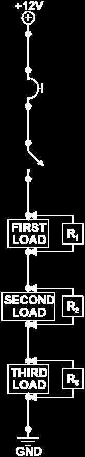
60 Exercise 1 Build the circuit shown. Note that the Load has changed from the last circuit. 54
61 1. Measure the Applied Voltage between the +12V Source and Ground 2. Measure the Voltage Drop across the Circuit Breaker 3. Measure the Voltage Drop across the Toggle Switch 4. Measure the Voltage Drop across the Load 5. What is the sum of the Voltage Drops in Questions 2, 3, and 4? 6. How does this total compare to the Applied Voltage? 7. Why? 8. How does the Voltage Drop across this Load compare to the Voltage Drop across the Load in the last circuit? 9. Why is this so? 10. Use the DVOM (Ohmmeter function) to measure the Circuit Resistance between the Source Jack and Ground (remember to turn off the Power, remove the wire, and close SW). What Resistance value do you measure? 11. Measure the Resistance across the Circuit Breaker 12. Measure the Resistance across Toggle SW 13. Measure the Resistance across the Load (bulb) 14. Add the measurements from steps 11, 12, and 13. What is the total? 15. How does the Resistance total in Question 14 compare to the Resistance you measured in Question 10? 16. Is this the result you expected? 17. Remove the wire between the +12V Source and the Circuit Breaker and measure the Current at this point. What is the Current flow between these two points? 18. Return the last wire and remove the wire between the Circuit Breaker and the Switch and measure the Current at this point. What is the Current flow between these two points? 19. Return the last wire and remove the wire between the Switch and the Load (Bulb) and measure the Current at this point. What is the Current flow between these two points? 20. Return the last wire and remove the wire between the Load (Bulb) and Ground and measure the Current at this point. What is the Current flow between these two points? 21. What do you notice about these four Current measurements? 22. Is this the result you expected? 55
62 23. How do your measurements in this Series Circuit compare to those in the previous Circuit relative to: Voltage Resistance Current At this point there are a couple of items to note concerning these two Series Circuits with different loads: 1) The Voltage, Resistance, and Current test procedures are the same for both and the Series Circuit Rules apply to both and, 2) While the circuit Resistance of the second circuit was higher, the circuit Current was lower. This is an important relationship that we will cover at a later time. Before we continue further, it s time to introduce some new electrical terms and abbreviations that will be used going forward. Some of them were already used in the last section but it is important that we cover all of them here. 1) Since all loads (bulbs, resistors, etc.) are resistances, they will now be shown with subscripts such as R 1, R 2, R 3, etc. The Total Circuit Resistance would likewise be designated by R T and a Switch Resistance would be R SW. 2) Any Voltage Drop measurement will also use subscripts to denote the item being tested for Voltage. For example, Voltage Drops across the loads would be E R1, E R2, etc (remember the term Electromotive Force or 'E') while the Switch Voltage would be E SW and the Applied Voltage would be E APP. 3) Current is shown using similar notations such as I T for Total Circuit Current and I R1, I R2, I R3, etc for the Currents through individual loads. With those new vocabulary additions in hand, let s move on to the next circuit. 56
63 This page intentionally left blank 57

64 Exercise 2 Build the circuit shown below and note that the Load is now a 120 Ω resistor instead of a bulb. A resistor is an electrical component that introduces a resistance into a circuit and therefore opposes Current flow. 58
65 In this exercise students will be asked to state what they expect a value to be before making an actual measurement. Turn on SW and make the following measurements using a DVOM. 1. Applied Voltage (E APP ) between the +12V Source and Ground Expected 2. Voltage Drop across the Circuit Breaker (E CB ) Expected 3. Voltage Drop across the Switch (E SW ) Expected 4. Voltage Drop across the Load (E R1 ) Expected Actual Actual Actual Actual 5. Do your measurements match the Series Circuit Rules concerning Voltage Drops? Why or Why not? 6. What must we do first before making Resistance measurements? 7. Use an Ohmmeter to measure the Total Circuit Resistance (R T ) between the Source Jack and Ground (close SW). Expected 8. Resistance across the Circuit Breaker (R CB ) Expected 9. Resistance across the Switch (R SW ) Expected 10. Resistance across the Load (R 1 ) Expected Actual Actual Actual Actual 11. Do these measurements match the Series Circuit Rules concerning resistances? Why or Why not? Make sure to turn the power back on here 12. Measure the Current between the +12V Source and the Circuit Breaker (I Source-CB ) Actual 13. Measure the Current between the Circuit Breaker and the Switch (I CB-SW ) Actual 59
66 14. Measure the Current between the Switch and the Load (I SW R1 ) Actual 15. Measure the Current between the Load and Ground (I R1-GND ) Actual 16. Do these measurements match the Series Circuit Rules concerning Currents? Why or Why not? 17. Which of these two statements is true? a) Total Current (I T) = (I Source-CB )= (I CB-SW )= (I SW R1 )= (I R1-GND ) or b) Total Current (I T) = (I Source-CB ) + (I CB-SW ) + (I SW R1 ) + (I R1-GND ) 18. How do your measurements in this Series Circuit compare to those in the previous Circuits relative to: Voltage Resistance Current Was that too easy? Are you ready to step it up a notch? OK here we go. 60
67 This page intentionally left blank 61


68 Exercise 3 Build the circuit shown below and note that there are now two loads, R 1 and R 2. 62
69 In this exercise students will again be asked to state what they expect a value to be before making an actual measurement. 1. Applied Voltage (E APP ) between the +12V Source and Ground Expected 2. Voltage Drop across the Circuit Breaker (E CB ) Expected 3. Voltage Drop across the Switch (E SW ) Expected 4. Voltage Drop across the first Load (E R1 ) Expected 5. Voltage Drop across the second Load (E R2 ) Expected Actual Actual Actual Actual Actual 6. Why are E R1 and E R2 different than the Load Voltage Drops in previous circuits? 7. Does it make sense that E R1 and E R2 are the same? 8. Do your measurements still match the Series Circuit Rule concerning Voltage Drops? Why or Why not? 9. Use an Ohmmeter (you know what comes first) to measure the Total Circuit Resistance (R T ) between the Source jack and Ground (close SW). Expected 10. Resistance across the Circuit Breaker (R CB ) Expected 11. Resistance across the Switch (R SW ) Expected 12. Resistance across the Load (R 1 ) Expected 13. Resistance across the Load (R 2 ) Expected Actual Actual Actual Actual Actual 14. Do these measurements still conform to the Series Circuit Rule concerning resistances? Why or Why not? 63
70 Make sure to turn the power back on here 15. Measure the Current between the +12V Source and the Circuit Breaker (I Source-CB ) Actual 16. Measure the Current between the Circuit Breaker and the Switch (I CB-SW ) Actual 17. Measure the Current between the Switch and the Load (I SW R1 ) Actual 18. Measure the Current between the first Load and the second Load (I R1 R2 ) Actual 19. Measure the Current between the second Load and Ground (I R2-GND ) Actual 20. Do these measurements match the Series Circuit Rules concerning Currents? Why or Why not? 21. Why are the bulbs dimmer in this circuit than they were in the first circuit you built using one of the very same bulbs? 22. Now that our circuit has multiple loads, does it still qualify as a Series Circuit? Why or Why not? If any of the measurements, or their designations, in this circuit were difficult for you to understand, the following graphics (for Voltage and Resistance measurements in multiple-load circuits) may help. 64


71 Now let s look at another variation of this circuit. 65

72 Exercise 4 Build the circuit shown below and note that there are still two loads but R 1 and R 2 have changed. 66
73 Measure and record the values as before. 1. Applied Voltage (E APP ) between the +12V Source and Ground Expected Actual 2. Voltage Drop across the Circuit Breaker (E CB ) Expected Actual 3. Voltage Drop across the Switch (E SW ) Expected Actual 4. Voltage Drop across the first Load (E R1 ) Expected Actual 5. Voltage Drop across the second Load (E R2 ) Expected Actual 6. How are E R1 and E R2 different than those in the previous circuit? 7. Does it make sense that E R1 and E R2 are still the same as each other? 8. Do your measurements still match the Series Circuit Rule concerning Voltage Drops? Why or Why not? 9. Measure the Total Circuit Resistance (R T ) between the Source jack and Ground (close SW). Expected 10. Resistance across the Circuit Breaker (R CB ) Expected 11. Resistance across the Switch (R SW ) Expected 12. Resistance across the Load (R 1 ) Expected 13. Resistance across the Load (R 2 ) Expected Actual Actual Actual Actual Actual 14. Notice that in Questions 12 and 13 that the resistance value is about half of the Total Resistance. Why do you think that is? 67
74 15. Do these measurements still match the Series Circuit Rule concerning resistances? Why or Why not? Power on 16. Since we have already determined that the Resistance is different in this circuit as compared to the last, would you expect the Current to be Higher, Lower, or Unchanged from the last circuit? 17. Measure the Current between the +12V Source and the Circuit Breaker (I Source-CB ) Expected Actual 18. Measure the Current between the Circuit Breaker and the Switch (I CB-SW ) Expected Actual 19. Measure the Current between the Switch and the Load (I SW R1 ) Expected Actual 20. Measure the Current between the first Load and the second Load (I R1 R2 ) Expected Actual 21. Measure the Current between the second Load and Ground (I R2-GND ) Expected Actual 22. Do these measurements conform to the Series Circuit Rules concerning Currents? Why or Why not? 23. Why are the bulbs dimmer in this circuit than they were in the previous circuit when both circuits used two identical bulbs? 68
75 Now that you have some experience using and measuring for Voltage, Resistance, and Current, it is a good time to cover some important information on the relationships between these three values. Those relationships are known as Ohm s Law. 69
76 This page intentionally left blank 70

77 VII. OHM S LAW Ohm s Law was first discovered by a German Physicist named Georg Simon Ohm in 1827 and, as stated previously, explains the interactive relationships between not only Voltage, Resistance, and Current, but also Power. The discoveries were so significant that the unit of Resistance, the OHM, was named in his honor. In order to adequately understand Ohm s Law s Electrical Relationships, it is necessary to first understand the different natures of the three primary electrical attributes. They are: 1. Voltage (or Electrical Potential, or Electrical Pressure, or Electromotive Force) is Applied. Recall from our original explanation of Voltage that the greater the number of electrons collected in a given place, the higher the voltage will be. As such, Voltage can be controlled either higher or lower by varying the number of those electrons. The primary concept students need to remember is that Voltage is just a 'Pushing Force' and that it does not flow through a circuit. Also, Voltage can exist without Current just as water pressure can exist in a hose without water flow. As an example, lightening is only a large voltage until it actually strikes. 2. Resistance Exists. Whether the resistance is a bulb, resistor, coil, motor, etc. everything has some amount of resistance based on its length, width, thickness, distance, separation, material it is made of, temperature, and so on. Materials that have low resistances (such as metals) are called Conductors and are often used as wires and connectors. Other substances have high resistances (like rubber, and plastics) and are called Insulators. Insulator materials are typically used to prevent electrical conduction in places such as wire coatings. By altering the variables of a substance such as length, width, etc. we can either increase or decrease that substance s resistance. 3. Current is Resultant. What this means is that when a certain Voltage is applied to a certain Resistance, a certain Current will be the result. While both Voltage and Resistance can be changed independently, Current cannot. Current is always varied by changing either the Voltage or Resistance and therefore it is not possible to just 'Turn up the Current'. To look at it another way, Voltage tries to push electrons through a substance and Resistance tries to hold them back. Also, it is important to remember that it is only Current which flows in an electrical circuit. In review: Voltage is Applied Resistance Exists Current Results This example shows a Current which results from some Voltage applied to some resistance. 71

78 That brings us to the first part of Ohm s Law a. If Resistance stays the same; an Increase in Voltage will cause an Increase in Current b. If Resistance stays the same; a Decrease in Voltage will cause a Decrease in Current and the second part of Ohm s Law is a. If Voltage stays the same; an Increase in Resistance will cause a Decrease in Current b. If Voltage stays the same; a Decrease in Resistance will cause an Increase in Current If you look back over the last four Exercises that have been completed, you will be able to see the effect of the Second part of Oh s Law where the Voltage was held constant but the load resistance changed. In addition to these two Ohm s Law relationships, there are also a number of mathematical formulas that allow us to calculate an unknown value for one of the attributes if we know the other two. For instance, if we know the Voltage and Resistance in a circuit, we can calculate what the Current should be. Likewise, if we have Voltage and Current values, it is possible to calculate an unknown Resistance. 72


79 The Ohm s Law formulas are: a. Voltage equals Current times Resistance or E = I x R b. Resistance equals Voltage divided by Current or R = E/I c. Current equals Voltage divided by Resistance or I = E/R Note: Georg Ohm originally developed only the equation E=IxR for Voltage. The other two for Resistance and Current are derived through algebra using substitution. An easy way to remember these formulas is by using a Solving Circle such as this In order to use the Solving Circle, all you need to do is cover up the value you want and the remaining factors will provide the necessary formula. For instance, if you are trying to find an unknown Voltage, simply cover 'E' on the circle and the correct formula (I x R) will remain. 73
.")

 1V 1Ω I = 2) 2A 100Ω E = 3) 12V 1A R = 4) 12V 5Ω I = 5) 240Ω 500mA E = 6) 30V 4A R = 7) 24V 1.")
80 likewise covering the 'I' for an unknown Current leaves E/R. and covering the 'R' for an unknown Resistance leaves E/I. Important!! All Ohm s Law calculations must be made using only Base Units (Volts, Ohms, and Amps). Any values that are not in Base Units such as KΩ, mv, ma, etc. must first be converted to Base Units before applying an Ohm s Law formula. Let s try a few examples Solve for the unknown variable. 1) 1V 1Ω I = 2) 2A 100Ω E = 3) 12V 1A R = 4) 12V 5Ω I = 5) 240Ω 500mA E = 6) 30V 4A R = 7) 24V 1.6KΩ I = 8) 20mA 680Ω E = 9) 100V 25μA R = 10) 5V 180Ω I = 11) 15A 8Ω E = 12) 28V 11.2A R = Now that you have had some practice calculating Ohm s Law, let s return to our Series Circuits and apply the laws along with our circuit rules. 74
81 VIII. SERIES CIRCUITS (continued) 75
82 Exercise 5 Build and measure the following circuit. 76
83 1. Measure Applied Voltage (E APP ) between the +12V Source and Ground 2. Measure the Total Circuit Resistance R T 3. What is the Ohm s Law formula for finding Current? 4. Using Ohm s Law, calculate the Total Circuit Current I T 5. Measure I T 6. Do the two closely match? This comparison proves that the formula works. 7. Measure the Voltage Drop (E R1 ) across the load 8. Using Ohm s Law, calculate the Load Current I R1 9. How does the Load Current in Question 8 compare to the Total Current in Question 4? 10. Do your findings in Question 9 make sense? 11. What do your answers in Questions 1 and 7 tell you about the rest of the circuit? Change the Power Source from the 12V jack to the 5V jack 12. Measure E APP 13. Measure R T 14. Using Ohm s Law, calculate the Total Circuit Current I T 15. Measure I T 16. What do Questions prove? NOTE: It s worth noting that not only did a reduction in Voltage (from 12V to 5V) cause a reduction in Current, but it caused a proportional reduction. That means that when the Voltage fell by 58% (from 12V to 5V), the Current also fell by 58% (100mA to 42mA). This is not always the case, as we will see later, but it does often apply. For the next exercise, return the Power Source to the 12V jack. 77


84 Exercise 6 Build and measure the following circuit. Notice that it has a larger load than the last one. 78
85 1. Measure Applied Voltage (E APP ) between the +12V Source and Ground 2. Measure the Total Circuit Resistance R T 3. What is the Ohm s Law formula for finding Current? 4. Using Ohm s Law, calculate the Total Circuit Current I T 5. Measure I T 6. Do the two closely match? 7. Measure the Voltage Drop (E R1 ) across the load 8. With the result from Question 7, what do you know about the circuit without making any other measurements? 9. Without measuring, how should the Load Current in this circuit compare to the Total Current? 10. How does the Current in this circuit compare to the Current in Exercise 5? 11. Why? 12. What do the results of this circuit prove? 13. In the last Exercise we found that the change in Current was proportional to the change in Voltage. Was the change in this circuit also proportional? In the next exercise, we ll apply Ohm s Law to Series Circuits with multiple loads 79
86 Exercise 7 Build and measure the following circuit with two identical loads. 80
87 1. Measure Applied Voltage (E APP ) between the +12V Source and Ground 2. Measure R 1 3. Measure R 2 4. Measure the Total Circuit Resistance R T 5. Using Ohm s Law, calculate the Total Circuit Current I T 6. Measure I T 7. Do the two closely match? 8. Measure the Voltage Drop (E R1 ) across the 1 st load 9. Measure the Voltage Drop (E R2 ) across the 2 nd load 10. Do your findings in Questions 8 and 9 make sense? 11. Using Ohm s Law, calculate I R1 12. Using Ohm s Law, calculate I R2 13. How do the currents in Questions 11 and 12 compare? 14. Why? 15. How do the currents I R1 and I R2 vary from I T? 16. Why? 17. In this Exercise we had a Total Resistance (R T ) of 240Ω and a corresponding Total Current (I T ) of 50mA. These are the same values we found in the last Exercise which only had a single load. Can multiple loads cause the I T to be different if the Total Resistance is the same? 81
88 Exercise 8 Build and measure the following circuit with identical but different loads. 82
89 1. Measure Applied Voltage (E APP ) between the +12V Source and Ground 2. Without measuring, estimate what R T should be for this circuit 3. How did you come up with that value? 4. Measure the Total Circuit Resistance R T 5. Using Ohm s Law, calculate I T 6. Measure I T 7. Do the two closely match? 8. How does this compare to the I T from the last Exercise? 9. Why? 10. Based on what you have learned previously, what do you think will be the value for E R1? For E R2? Why? 11. Measure the Voltage Drop (E R1 ) across the 1 st load 12. Measure the Voltage Drop (E R2 ) across the 2 nd load 13. Based on your findings in Questions 11 and 12, were your answers correct for Question 10? 14. Show the formula for calculating I R1 15. Show the formula for calculating I R2 16. Without measuring I R1 and I R2, how can you be sure your answers are correct? NOTE: In Question 4, Total Circuit Resistance, R T, was determined by measuring with a DVOM. This type of resistance measurement can be called a 'static Resistance' since the circuit is not operating. In some applications, which we will see later, it will be necessary to determine the 'Dynamic Resistance' or 'Operating Resistance' of a circuit. This type of resistance measurement can not be done with a DVOM and must be accomplished with an Ohm s Law calculation using Voltage and Current values. 83
90 Exercise 9 Build and measure the following circuit with two different loads. 84
91 1. Measure Applied Voltage (E APP ) between the +12V Source and Ground 2. Without measuring, estimate what R T should be for this circuit 3. Measure the Total Circuit Current I T 4. What is the Ohm s Law formula for calculating R T? 5. Calculate R T 6. Measure R T 7. Do the two closely match? 8. Do your measurements match the estimate from Question 2 which was based on the listed values of the loads? 9. Is this circuit Current higher or lower than the previous circuit? 10. Why? 11. Based on what you have learned previously, do you think the voltage drops across R 1 and R 2 will be the same, higher for R 1, or higher for R 2? 12. Why? 13. Calculate the Voltage Drop (E R1 ) across the 1 st load 14. Calculate the Voltage Drop (E R2 ) across the 2 nd load 15. Measure the Voltage Drop (E R1 ) across the 1 st load 16. Measure the Voltage Drop (E R2 ) across the 2 nd load 17. Based on your findings in Questions 13 16, did your measurements match your calculations? 18. In comparing the measured values for E R1 and E R2 in Questions 15 and 16, how do you explain the difference in the values? 85
92 Exercise 10 Build and measure the following circuit with the same loads in reverse position. 86
93 1. Measure Applied Voltage (E APP ) between the +12V Source and Ground 2. Without measuring, estimate what R T should be for this circuit 3. Using the Voltage and Resistance from Questions 1 and 2, estimate I T 4. Measure the Total Circuit Current I T 5. How does this I T compare to I T in the previous circuit? 6. Why? 7. Calculate R T using the measured Current 8. Measure R T 9. Based on what you have learned previously, do you think the voltage drops across R 1 and R 2 will be the same, higher for R 1, or higher for R 2? 10. Why? 11. Calculate the Voltage Drop (E R1 ) across the 1 st load 12. Calculate the Voltage Drop (E R2 ) across the 2 nd load 13. Measure the Voltage Drop (E R1 ) across the 1 st load 14. Measure the Voltage Drop (E R2 ) across the 2 nd load 15. Did your calculated values match your measured values? 16. How do the measured values for I T, E R1, and E R2 in this circuit compare to those same values in the previous circuit? 17. In this circuit, the loads R1 and R2 are the same values as the previous circuit but their order is reversed. How does changing the order affect circuit operation? 87
94 Exercise 11 Build the following circuit but DO NOT turn on Switch 1 until told to do so. 88
95 1. Measure Applied Voltage (E APP ) between the +12V Source and Ground 2. Measure R 1 3. Turn on SW and measure the Total Circuit Current I T. 4. Based on what you have learned previously, what do you think should be the voltage drop across the load R 1? 5. Why? 6. Measure E R1. 7. Does the measured value match your expectation? 8. Using the measured Current from Question 3 and the measured Voltage Drop from Question 6, calculate the resistance of R Does this calculated value match your measured value from Question 2? 10. Why or why not? In all of our circuits up to this point, the calculated values of R 1, R 2, etc. have matched the actual measured values of those loads. In this circuit however, the calculated value turned out to be almost 10 times as high as the measured value. The reason is that some loads, such as bulbs and heating grids, actually increase their resistance as they get hot. Typically, the higher the current flow through a 'heating' load, the greater its resistance will be. The difference in the two Resistance values is the difference between a 'Static Resistance' and a 'Dynamic Resistance' (or 'Operating Resistance'). 89

96 Exercise 12 Build the following circuit using the other 14V bulb (since it is cold) but DO NOT turn on Switch 1 until told to do so. Note also that the Source Voltage is now 5V. 90
97 1. Measure Applied Voltage (E APP ) between the +12V Source and Ground 2. Measure R 1 3. Turn on SW and measure the Total Circuit Current I T. 4. Based on what you have learned previously, what do you think should be the voltage drop across the load R 1? 5. Why? 6. Measure E R1. 7. Does the measured value match your expectation? 8. Using the measured Current from Question 3 and the measured Voltage Drop form Question 6, calculate the resistance of R Does this calculated value match your measured value from Question 2? 10. Why or why not? 11. How does this calculated resistance for R 1 compare to the calculated R 1 value in the previous exercise? 12. How do you explain this? 91
98 Exercise 13 Build the following circuit using two 14V bulbs but DO NOT turn on the Switch (SW) until told to do so. 92
99 1. Measure Applied Voltage (E APP ) between the +12V Source and Ground 2. Measure R 1 3. Measure R 2 4. Calculate I T based on E APP and R T 5. Turn on SW and measure the Total Circuit Current I T. 6. Is this about the result you expected? 7. Why? 8. Based on what you have learned previously, what do you think the voltage drop across load R 1 should be? and across R 2? 9. Why? 10. Measure E R Measure E R Do the measured values match your expectation? 13. What would you expect the Current through R 1 to be? 14. Why? 15. What about the Current through R 2? 16. Why? 17. If the two bulbs in this circuit were replaced with the higher resistance 28V bulbs, what would be the values for E R1 and E R2? 18. Why? 19. If the two bulbs in this circuit were replaced with the higher resistance 28V bulbs, what would happen to the Total Circuit Current I T as compared to the 14V bulbs? 20. Replace the 14V bulbs with 28 V bulbs. Measure I T 21. Does your measurement in Question 20 verify your answer in Question 19? 93
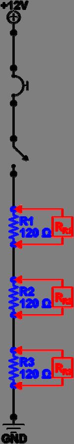
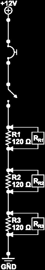
100 Exercise 14 Build and measure the following circuit with three identical loads. 94
101 1. Measure Applied Voltage (E APP ) between the +12V Source and Ground 2. Measure R 1 3. Measure R 2 4. Measure R 3 5. Measure R T 6. Is this Total Resistance value consistent with the measurements from Questions 2-4? 7. Calculate I T based on E APP and R T 8. Based on what you have learned previously, what do you think the voltage drops across each load will be? E R1 E R2 E R3 9. Why? 10. Measure E R Measure E R Measure E R Do the measured values in Questions match your expectations from Question 8? 14. What is the formula for calculating Current flow through the first load R 1? 15. Measure I R1 16. Is this figure consistent with what you would expect? 17. Why? 18. How would I R2 and I R3 compare with that of I R1? NOTE: Anytime there is a circuit with multiple loads of the same resistance, the Voltage Drop across each can be calculated by dividing the Total Voltage by the number of loads. For example, if the Applied Voltage is 12V and there are two equal loads in a circuit, then the Voltage Drop across each load will be 6Volts. If there are three equal loads then the Voltage Drop will be 4Volts for each, and 3Volts for each if a fourth equal load is added. 95

102 Power Up to this point, we have put significant effort into understanding the three primary attributes (Voltage, Resistance, and Current) of Electricity and Electrical Circuits. It is now time to introduce a fourth component, Power. Unlike the other three, Power is not an independent component of electrical circuits, but rather it is a measure of how much energy is used to do work (light a bulb, turn a motor, etc.) over a certain period of time. The unit of measure for Power is the Watt, which is defined as using one Joule of Energy per Second. Recall how we earlier defined the three Primary Electrical Attributes; we said that: Voltage is APPLIED Resistance EXISTS and Current is RESULTANT Along those same lines we should look at Power as CONSUMED. That means that it is a measure of how much 'electricity' is used up as a circuit operates. Just as there are formulas to calculate Voltage, Resistance, and current, there is a way to calculate Power actually there are three ways. The basic formula for Power is: Power = Current x Voltage which is written as P = I x E. Since we know from Ohm s Law that I = E/R, we can substitute that into our Power equation which will give us the formula P = (E/R) x E and then simplify to P = E 2 /R. 96
.")
103 Likewise, also from Ohm s Law, we know that E = I x R. If we substitute that for E in the original formula it gives us P = I x (I x R) which simplifies to P = I 2 x R. So we now have three Power formulas which can be used with any two of the Primary Attributes (Voltage, Resistance, and Current). In short, the formulas to use will be: P = I x E P = E 2 /R P = I 2 x R (If you know Current and Voltage but not Resistance) (If you know Voltage and Resistance but not Current) (If you know Current and Resistance but not Voltage) Remember that, just as we found with other Ohm s Law formulas, all values must be in Base Units (Volts, Ohms, and Amps) before making any calculations. Let s try some examples: 1. If Voltage is 12V and Current is 2A, Power will be 2. If Voltage is 6V and the Resistance is 10Ω, Power will be 3. If Current is 500 ma and Resistance is 5 Ω, Power will be 97
 until told to do")
104 Exercise 15 Build the following circuit using two 14V bulbs but DO NOT turn on the Switch (SW) until told to do so. 98
105 1. Measure Applied Voltage (E APP ) between the +12V Source and Ground 2. Measure R 1 3. Measure R 2 4. Measure R T 5. Calculate I T based on E APP and R T 6. Measure I T 7. Calculate actual R T based on E APP and measured I T 8. Measure E R1. 9. Measure E R What formula would you use to calculate Power for this circuit? 11. Calculate P T 12. Calculate P R1 13. Calculate P R2 14. What would happen to the Total Power consumption (P T ) of a circuit if Applied Voltage doubled and the Total Current was cut in half? 15. Verify your answers in Questions 12 and 13 by performing the calculations again using the other two Power equations. The next three exercise schematics and measurement pages are intended for use by Instructors and/or students to build and test Series Circuits of their own design. If more than three blanks are needed, extra copies can be made. After that, we will move on to the next type of circuit, the Parallel Circuit. 99
106 Customized Circuit Exercise Build and measure the following circuit according to the Instructor s directions. 100
107 1. Measure Applied Voltage (E APP ) between the +12V Source and Ground 2. Measure R 1 3. Measure R 2 4. Measure R 3 5. Measure R 4 6. Measure I RT 7. Calculate R T 8. Measure R T 9. Does the Calculated R T equal the Measured R T? 10. Should it? 11. Calculate E R1 12. Calculate E R2 13. Calculate E R3 14. Calculate E R4 15. Measure E R1 16. Measure E R2 17. Measure E R3 18. Measure E R4 19. Do the Calculated values in match the Measured values in 15 18? 20. Should they? 21. Do the Measured values across the loads add up to the Applied Voltage? 22. Calculate Total Circuit Power (P T ) 23. Calculate the Power consumed by R 1 (P R1 ) 24. Calculate the Power consumed by R 2 (P R2 ) 25. Calculate the Power consumed by R 3 (P R3 ) 26. Calculate the Power consumed by R 4 (P R4 ) 101
108 Customized Circuit Exercise Build and measure the following circuit according to the Instructor s directions. 102
109 1. Measure Applied Voltage (E APP ) between the +12V Source and Ground 2. Measure R 1 3. Measure R 2 4. Measure R 3 5. Measure R 4 6. Measure I RT 7. Calculate R T 8. Measure R T 9. Does the Calculated R T equal the Measured R T? 10. Should it? 11. Calculate E R1 12. Calculate E R2 13. Calculate E R3 14. Calculate E R4 15. Measure E R1 16. Measure E R2 17. Measure E R3 18. Measure E R4 19. Do the Calculated values in match the Measured values in 15 18? 20. Should they? 21. Do the Measured values across the loads add up to the Applied Voltage? 22. Calculate Total Circuit Power (P T ) 23. Calculate the Power consumed by R 1 (P R1 ) 24. Calculate the Power consumed by R 2 (P R2 ) 25. Calculate the Power consumed by R 3 (P R3 ) 26. Calculate the Power consumed by R 4 (P R4 ) 103


110 Customized Circuit Exercise Build and measure the following circuit according to the Instructor s directions. 104
111 1. Measure Applied Voltage (E APP ) between the +12V Source and Ground 2. Measure R 1 3. Measure R 2 4. Measure R 3 5. Measure R 4 6. Measure I RT 7. Calculate R T 8. Measure R T 9. Does the Calculated R T equal the Measured R T? 10. Should it? 11. Calculate E R1 12. Calculate E R2 13. Calculate E R3 14. Calculate E R4 15. Measure E R1 16. Measure E R2 17. Measure E R3 18. Measure E R4 19. Do the Calculated values in match the Measured values in 15 18? 20. Should they? 21. Do the Measured values across the loads add up to the Applied Voltage? 22. Calculate Total Circuit Power (P T ) 23. Calculate the Power consumed by R 1 (P R1 ) 24. Calculate the Power consumed by R 2 (P R2 ) 25. Calculate the Power consumed by R 3 (P R3 ) 26. Calculate the Power consumed by R 4 (P R4 ) 105
112 This page intentionally left blank 106


113 IX. PARALLEL CIRCUITS Up to this point we have dealt only with Series Circuits which are defined as 'Any circuit that has only one path for current to flow'. Now we will expand on what we have learned to include Parallel Circuits. First, a definition of Parallel Circuits: Definition: A Parallel Circuit is 'Any circuit that has more than one path for current to flow'. Build the following circuit: Notice in this circuit that Current has only one path in which to flow as it passes through the Circuit Breaker and the Switch. After that, however, it can go in either of two directions; through R 1 or R 2. Each of the paths that Current can take through the loads is called a 'Circuit Branch' or just 'Branch'. 107
 are equal, the Currents through each Branch will be equal.")
 is connected to the same Voltage Source and each is also connected to the same Ground.")
114 Because it has multiple paths to follow, the Current will split between the two Branches, depending on the Resistances of each Branch. If the loads (resistances) are equal, the Currents through each Branch will be equal. However, if the loads are not equal, the Branch with the larger resistance will have a lower Current flow and the Branch with the lowest resistance will have the largest Current flow. Notice that each Branch (BR) is connected to the same Voltage Source and each is also connected to the same Ground. Therefore, the Voltage Drop across each Branch will be the same as each of the other Branches. Also, because there are multiple paths for current to flow, the resistances of the Branches will not be added together as we found in Series Circuits. Rather, the overall Total Resistance of the branches (also called Equivalent Resistance or R EQ ) will be less than any of the Branch Resistances. Now, just as we had three Rules for Series Circuits, we also have three Rules for Parallel Circuits. They are: Rule #1: The Voltage Drop across any Branch of a Parallel Circuit is always equal to the Voltage Drop of every other Branch of that Circuit. Rule #2: The Total Resistance of the Branches in a Parallel Circuit (or Equivalent Resistance) is always LESS than the Resistance of the lowest resistance Branch. Rule #3: The Total Current, I T, in a Parallel Circuit is equal to the sum of the Branch Currents. Keep in mind that all of Ohm s Law, including the calculation formulas, still applies to Parallel Circuits just as it did for Series Circuits. There is, however, one additional formula for Parallel Circuits which involves calculating the Equivalent Resistance (R EQ ) for the Branches of that circuit. That formula is: Where n represents the total number of branches. 108


115 The example below is a Parallel circuit with two branches. One branch has a 10Ω resistance and the other a 20Ω resistance. According to Rule #2, this Equivalent Resistance should be less than the lowest Branch Resistance. Since our lowest Branch Resistance in this case is 10 Ω, and 6.7 Ω is less than that, then we know that our calculation is probably correct. Now let s apply all of this to another circuit. 109

116 Exercise 16 Build and measure the Parallel circuit below: 110
117 1. Measure Applied Voltage (E APP ) between the +12V Source and Ground 2. Measure R 1 3. Measure R 2 4. Measure R T 5. Does the Measured R T equal R 1 and R 2? 6. Should it? 7. Using the values from Questions 2 and 3, calculate R EQ 8. Does the Calculated R EQ equal the Measured R T? 9. Should it? 10. Turn on the Power and Measure E R1 11. Measure E R2 12. Are they equal? 13. Should they be? 14. Why or why not? 15. Measure I R1 16. Measure I R2 17. Measure I T 18. Are the three currents equal? 19. Should they be? 20. What is the relationship between I RT, I R1, and I R2? 21. Why? 22. What formula should be used to calculate E R1? 23. Calculate E R1 24. Calculate E R2 25. Do the Voltage Drop calculations in questions 23 and 24 match the measured results in questions 10 and 11? 26. Should they? 27. Do the Measured Voltages across the loads (E R1 and E R2 ) add up to the Source Voltage? 28. Should they? 29. What formula should be used to calculate R 1? 30. Calculate R Calculate R 2 111
118 32. Do the Resistance calculations in questions 30 and 31 match the measured results in questions 2 and 3? 33. Should they? 34. What formula should be used to calculate I R1? 35. Calculate I R1 36. Calculate I R2 37. Do the Current calculations in Questions 35 and 36 match the measured results in questions 15 and 16? 38. Should they? 39. Calculate I T based on E APP and R T 40. Do the calculated Currents through the loads (I R1 and I R2 ) in Questions 35 and 36 add up to the calculated Total Current I T in Question 39? 41. Should they? 42. Is the calculated Total Current (I T ) in Question 39 equal to the measured Total Current from Question 17? 43. Should it? 44. Calculate Total Circuit Power (P T ) 45. Calculate the Power consumed by R 1 (P R1 ) 46. Calculate the Power consumed by R 2 (P R2 ) 47. Do the Power calculations of the two branches (P R1 and P R2 ) equal the Total Circuit Power (P T )? 48. Should they? 112
119 Since the previous Exercise is our first with Parallel Circuits, let s take this opportunity to go over the answers to each of the questions. That will help to insure that students understand the procedures, including measurements and calculations that will be used with Parallel Circuits. You can refer back to the information from this Exercise later on if needed. 113
120 Exercise 16 Evaluation and Results: 1. Applied Voltage should be measured between the Source Terminal and Ground just as in Series Circuits. Answer: 12V 2. Measuring a branch resistance such as R 1 is different for Parallel Circuits than Series Circuits. In a Series Circuit it is a simple matter of removing 12V or Ground and placing the leads of an Ohmmeter across the load. However, for Parallel Circuits the load must be further removed from the unpowered circuit. Notice that if you take your DVOM leads (set to Ohms) and place them across R 1, they are, at the same time, also across the second load, R 2 by way of the wires that connect them. In this arrangement, what you are actually measuring is not just R 1 but rather BOTH R 1 and R 2. In fact, this measurement is actually the Equivalent Resistance of R 1 and R 2, or R EQ. To avoid this problem, make sure that at least one end of the load being measured is completely disconnected from the circuit before testing its resistance. Answer should be about 5Ω. If your resistance was around 2.5 Ω, then you actually measured across both loads. 3. Measuring this would require the same procedure as the load in Question 2. Answer should be about 5Ω. 4. Total Resistance (R T ) is NOT exactly the same thing as Equivalent Resistance (R EQ ) although it will often give the same result, depending on the circuit. Total Resistance, or Total Circuit Resistance, should be measured from the Applied Voltage point to the Ground point, with the Power turned OFF. Equivalent Resistance (R EQ ) is measured across only the Branches of the circuit. If the loads in the branches are the only resistances in the circuit, then R T will equal R EQ. The answer here should be about 2.5 Ω. 5. R T SHOULD NOT equal R 1 and R 2 (R T R 1 + R 2 ). If the resistances of the branches were measured incorrectly, as laid out in Step #2, then the results for R T would read the same R 1 and R 2, at 2.5 Ω apiece. However, if R 1 and R 2 are measured correctly, then R T will be lower. Note: if you happened to notice that the Total Resistance (R T ) is half as much as either of the branch resistances, R 1 and R 2, don t assume that will always be the case. Such a situation will only happen when there are two loads of the same resistive value. Answer should be NO. 6. Answer should be NO for the reasons stated in #5. 7. The formula here would be 1/R EQ = 1/R 1 + 1/R 2» 1/R EQ = 1/5Ω + 1/5Ω» 1/R EQ =.2Ω +.2Ω» 1/R EQ =.4Ω» R EQ = 1/.4Ω» R EQ = 2.5Ω Answer is 2.5Ω 8. Calculated R EQ should equal the Measured R T when the calculation is done with an Unpowered circuit, even with heating loads that change resistance. An R EQ calculation would give different results in this circuit if it were powered, which will be shown later. Answer is YES. 9. Answer is YES they should be equal since the power is off. 10. Since the top of this bulb is connected to 12V and the bottom is connected directly to Ground, the Voltage across this load should be 12V. If it isn t, there is a problem in the circuit. Answer is 12V. 114
121 11. This measurement is actually the same as in #10 since both have the same connections. Recall that one of the Rules of Parallel Circuits says that the Voltage Drop across each branch circuit will be the same. Answer is 12V. 12. They should be see #s 10 and 11. Answer is YES. 13. Yes they should by Rule #1. Answer is YES. 14. Both have the same Applied Voltage and Ground 15. Unlike Series Circuits, where Current is the same everywhere, the branches in Parallel circuits carry different currents. When measuring I R1, it is necessary to break the circuit either between the load and the point where it connects to the Positive side of the 'Main' circuit, or between the load and the point where it connects to the Negative side of the 'Main' circuit. A failure to 'isolate' the branch like this could result in an incorrect reading, including a Total Current reading. Answer should be.240a or 240mA. 16. This measurement would be made the same as in #15 except with the other branch. Since both loads are the same, and the Voltage Drops are the same (as shown in #s 10 and 11), then the currents will be the same. Answer should be.240a or 240mA. 17. This measurement should be made to reflect the entire circuit, which means it should include not only the branches, but rather all of the 'Main' circuit. The easiest way is usually between the Source jack and the top of the circuit or between the bottom of the circuit and the Ground jack. Since this would include both branch currents, the total would certainly be higher than either branch. If the measurement in either #15 or #16 were performed incorrectly, it is likely that the reading would actually be I T instead of a branch current. Answer should be.480a or 480mA. 18. If either branch current were measured incorrectly, then the measurements may have displayed the same. However, they should not be. Answer should be NO. 19. They should not as explained in #s Answer is NO. 20. I RT is the Current that flows through the Main Circuit but is split as it goes through the branches. It will then recombine after the loads, and become I RT again. As such, I RT is the combination of the branch currents. Answer: I RT = I R1 + I R2 21. See # Make sure when doing this calculation that you use the applicable factors. Since we are looking for the Voltage across the first load (E R1 ) we need to make sure we use the current through that load (I R1 ) and the resistance of that particular load (R 1 ) instead of Applied Voltage, Total Current, or Equivalent Resistance. Also note that this measurement would have to use the COLD resistance value since it isn t possible to directly measure resistance on an operating circuit. Answer is E R1 = I R1 x R 1 which comes straight from Ohm s Law. 23. Applying the formula from #22 we get E R1 =.240A x 5Ω. Answer is 1.2V. 24. Same as #23 but in the other branch E R2 =.240A x 5Ω. Answer is 1.2V. 25. The values in Questions 10 and 11 are 12Volts while in 23 and 24 they are 1.2Volts. Answer is NO. 26. They should not be since one is with COLD loads and the other is with HOT loads. Answer is NO. 27. Recall that in Parallel Circuits, the branches have the same Voltage Drops, which may or may not be the same as the Applied Voltage, depending on the rest of the circuit. As stated previously, the branch loads are connected to the same Voltage and Ground rather 115
122 than being tied to each other as in Series Circuits. Therefore the Voltages will not add up to the Source Voltage. Answer is NO. 28. See #27. Answer is NO, not in Parallel Circuits. 29. Since we need Voltage and Current to calculate Resistance, this circuit must be powered up. Also, make sure to use the correct factors in finding R 1 such as E R1 and I R1 rather than Applied Voltage and Total Current. Answer is R 1 = E R1 / I R Applying the formula from #29 we get R 1 = 12V /.240A = 50Ω. Answer is 50Ω. 31. Use the same procedure as in #30 for R 2 = E R2 / I R2 = 12V /.240A = 50Ω. Answer is 50Ω. 32. They should not. Answer should be NO. 33. They should not match since the answers in #2 and 3 used COLD bulbs in an unpowered circuit while those in #30 and 31 used HOT bulbs in a powered circuit. Answer is NO. 34. I R1 is the current that goes ONLY through the first load or branch. It is, again, important to use the correct factors to calculate this current. Those are, of course, the Voltage across the load (E R1 ) and the Resistance of the load (R 1 ). Since we must have a measured resistance to make this calculation (you can t calculate both Resistance and Current at the same time, one must be measured), this formula will have to use the COLD resistance value. Answer is I R1 = E R1 / R Applying the above formula we find I R1 = E R1 / R 1 = 12V / 5Ω. Answer is 2.4A. 36. I R2 is done in the same fashion as in #35. I R2 = E R2 / R 2 = 12V / 5Ω. Answer is 2.4A. 37. They shouldn t values from #35 and 36 are with an unpowered circuit while those from 15 and 16 used a powered circuit. Answer is NO. 38. They should not match since these are 'heating' loads. If they were 'non-heating' loads, they would be the same. Answer is NO. 39. Notice that this question asks for R T rather than R EQ. As such it would use I T = 12V / 2.5Ω Answer is 4.8A. 40. They should add up because both were done using the same circuit conditions (unpowered). Answer is YES. 41. Parallel Circuit Rule #3 says that the Total Current equals the sum of the individual branch currents. Answer is YES. 42. It shouldn t be since the operating conditions were different. Answer is NO. 43. One is operating with HOT loads and the other is unpowered. Answer is NO. 44. Since we are calculating Total Power (P T ), the two factors (Current and Voltage) must also be totals (I T and E T or E APP ). As such, we have P T =.480A x 12V 5.8W. Answer is about 5.8 Watts. 45. Again use the applicable factors, I R1 and E R1. P R1 =.240A x 12V. Answer is about 2.9 Watts. 46. Using the same procedure as in #45 we find P R2 = I R2 x E R2 =.240A x 12V. Answer is about 2.9 Watts. 47. In this case they happen to equal the total since there are no other Power losses in the circuit. Answer is YES. 48. Since there are no other Power losses in this circuit, they will be equal. However, that won t always be the case. Answer is YES. 116
123 This page intentionally left blank 117

124 Exercise 17 Build and measure the following Parallel circuit. 118
125 Note that this circuit is similar to the previous one in that both Branch Loads are still equal to each other; however, their resistances are different from the previous circuit. 1. Measure Applied Voltage (E APP ) between the +12V Source and Ground 2. Measure R 1 3. Measure R 2 4. Measure R T 5. Using the values from Questions 2 and 3, calculate R EQ 6. Does the Calculated R EQ equal the Measured R T? 7. Should it? 8. Turn on the Power and Measure E R1 9. Measure E R2 10. Are they equal? 11. Should they be? 12. Why or why not? 13. How do E R1 and E R2 on this circuit compare to E R1 and E R2 on the previous circuit which had different loads? 14. Why? 15. Measure I R1 16. Measure I R2 17. Based on Questions 15 and 16, what should I T be on this circuit 18. Why? 19. Measure I T 20. Does your Calculated Current match your Measured Current? 21. What formula should be used to calculate E R1? 22. Calculate E R1 23. Calculate E R2 24. Do the Voltage Drop calculations in questions 22 and 23 match the measured results in questions 8 and 9? 25. Should they? 26. What formula should be used to calculate R 1? 27. Calculate R Calculate R 2 119
126 29. Do the Resistance calculations in questions 27 and 28 match the measured results in questions 2 and 3? 30. Should they? 31. What formula should be used to calculate I R1? 32. Calculate I R1 using R 1 from Question Calculate I R2 using R 2 from Question Do the Current calculations in Questions 32 and 33 match the measured results in questions 15 and 16? 35. Should they? 36. Calculate I T based on E APP and R T 37. Do the Calculated Currents through the loads (I R1 and I R2 ) in Questions 32 and 33 add up to the calculated Total Current I T in Question 36? 38. Should they? 39. Is the calculated Total Current (I T ) in Question 36 equal to the measured Total Current from Question 19? 40. Should it? 41. Calculate the actual Total Circuit Power (P T ) 42. Calculate the actual Power consumed by R 1 (P R1 ) 43. Calculate the actual Power consumed by R 2 (P R2 ) 44. Do the Power calculations of the two branches (P R1 and P R2 ) equal the Total Circuit Power (P T )? 45. Should they? When comparing this circuit to the previous ones, students should understand that a difference in the Resistance of the branch loads will not change the branch Voltage Drops. However, the Branch Currents, the Total Current, the Branch Power consumptions, and the Total Circuit Power consumption will be affected by a change in either a Branch Resistance or the Total Circuit Resistance. Remember the Ohm s Law Rule: If Voltage remains constant; an Increase in Resistance causes a Decrease in Current, while a Decrease in Resistance will cause an Increase in Current. 120
127 This page intentionally left blank 121
128 Exercise 18 Build and measure the following Parallel circuit: 122
129 Note that this circuit still has two branches but the loads are not equal. 1. Measure Applied Voltage (E APP ) between the +12V Source and Ground 2. Measure R 1 3. Since this circuit has unequal loads, how does that change the value of R 1 and why? 4. Measure R 2 5. Since this circuit has unequal loads, how does the different value of R 1 affect the value of R 2 and why? 6. Measure R T 7. Should the value for R T be higher, lower, or equal to the Branch Resistances? 8. Why? 9. Using the values from Questions 2 and 4, calculate R EQ 10. Does the Calculated R EQ equal the Measured R T? 11. Should it? 12. How does R EQ compare to the values of R 1 and R 2? 13. Why? 14. Turn on the Power and Measure E R1 15. Measure E R2 16. Are they equal? 17. Should they be? 18. Why or why not? 19. How do E R1 and E R2 on this circuit compare to E R1 and E R2 on the previous circuit which had identical loads? 20. Why? 21. Measure I R1 22. Measure I R2 23. Are they equal? 24. Should they be? 25. Why or why not? 26. Based on Questions 21 and 22, what should I T be on this circuit? 123
130 27. Why? 28. Measure I T 29. Does your Calculated Current match your Measured Current? 30. What formula should be used to calculate E R1? 31. Calculate E R1 32. Calculate E R2 33. Do the Voltage Drop calculations in questions 31 and 32 match the measured results in questions 14 and 15? 34. Should they? 35. What formula should be used to calculate R 1? 36. Calculate R Calculate R Do the Resistance calculations in Questions 36 and 37 match the measured results in Questions 2 and 4? 39. Should they? 40. What formula should be used to calculate I R1? 41. Calculate I R1 using R 1 from Question Calculate I R2 using R 2 from Question Do the Current calculations in Questions 41 and 42 match the measured results in questions 21 and 22? 44. Should they? 45. Calculate I T based on E APP and R T 46. Do the Calculated Currents through the loads (I R1 and I R2 ) in Questions 41 and 42 add up to the calculated Total Current I T in Question 45? 47. Should they? 48. Is the Calculated Total Current (I T ) in Question 45 equal to the measured Total Current from Question 28? 49. Should it? 50. Calculate the actual Total Circuit Power (P T ) 51. Calculate the actual Power consumed by R 1 (P R1 ) 52. Calculate the actual Power consumed by R 2 (P R2 ) 53. Do the Power calculations of the two branches (P R1 and P R2 ) equal the Total Circuit Power (P T )? 54. Should they? 124
131 When comparing this circuit to those with identical loads (regardless of their values), students should understand that a difference in the Resistances of the branch loads will not change the branch Voltage Drops. However, the Branch Currents will be different which will, in turn, affect the Total Current and Power consumptions. Also, remember that the Equivalent Resistance of the branches of a Parallel Circuit will always be less than the Resistance of the least, or lowest, Branch Resistance. 125
132 Exercise 19 Build and measure the following Parallel circuit: 126
133 Note that this circuit has two branches with equal, but non-heating, loads. 1. Measure Applied Voltage (E APP ) between the +12V Source and Ground 2. Measure R 1 3. Measure R 2 4. Without measuring or calculating, determine the Equivalent Resistance, R EQ, of this circuit. 5. How did you determine this value? 6. Measure R EQ 7. Did the Measured R EQ from Question 6 match your Determined Value from Question 4? 8. Measure R T 9. How does the Measured R T value from Question 8 compare to the Measured R EQ value from Question 6? 10. What can you deduce from the findings in Question 9? 11. Using the values from Questions 2 and 3, calculate R EQ 12. Does the Calculated R EQ in Question 11 equal the Measured R EQ from Question 6? 13. Should it? 14. Why or why not? 15. How does R EQ compare to the values of R 1 and R 2? 16. Why? 17. Turn on the Power and Measure E R1 18. Measure E R2 19. Are they equal? 20. Should they be? 21. Why or why not? 22. How do E R1 and E R2 on this circuit compare to E R1 and E R2 on circuits that have bulbs as loads? 23. Why? 24. Measure I R1 127
134 25. Measure I R2 26. Are they equal? 27. Should they be? 28. Why or why not? 29. Based on Questions 24 and 25, what should I T be on this circuit? 30. Why? 31. Measure I T 32. Does your Calculated I T match your Measured I T? 33. What formula should be used to calculate E R1? 34. Calculate E R1 35. Calculate E R2 36. Do the Voltage Drop calculations in questions 34 and 35 match the measured results in questions 17 and 18? 37. Should they? 38. What formula should be used to calculate R 1? 39. Calculate R Calculate R Do the Resistance calculations in Questions 39 and 40 match the measured results in Questions 2 and 3? 42. Should they? 43. What formula should be used to calculate I R1? 44. Calculate I R1 using R 1 from Question Calculate I R2 using R 2 from Question Do the Current calculations in Questions 44 and 45 match the measured results in questions 24 and 25? 47. Should they? 48. Calculate I T based on E APP and R T 49. Do the Calculated Currents through the loads (I R1 and I R2 ) in Questions 44 and 45 add up to the Calculated Total Current I T in Question 48? 50. Should they? 51. Is the Calculated Total Current (I T ) in Question 48 equal to the Measured Total Current from Question 31? 52. Should it? 53. Calculate the actual Total Circuit Power (P T ) 128
135 54. Calculate the actual Power consumed by R 1 (P R1 ) 55. Calculate the actual Power consumed by R 2 (P R2 ) 56. Do the Power calculations of the two branches (P R1 and P R2 ) equal the Total Circuit Power (P T )? 57. Should they? When comparing this circuit to those with bulbs as loads, students should understand that Calculated and Measured values (Resistances and Currents) should be equal in this type of circuit since there is no increase in the resistances due to heat. Also, remember that the Voltage Drops across the Branch Loads will not be affected by the type of load, whether heating or nonheating. In addition, the Equivalent Resistance of the branches of a Parallel Circuit with non-heating loads will still be less than the resistance of the least, or lowest, Branch Resistance, and the Measured Equivalent Resistance (R EQ ) will match the Calculated Equivalent Resistance (R EQ ). 129
136 Exercise 20 Build and measure the following Parallel circuit: 130
137 Note that this circuit still has two branches with equal, but non-heating, loads. They are also of a higher resistance than in the last circuit. Before we begin taking measurements on this circuit, let s evaluate it and make some calculations. 1. What should be the Voltage Drop across each Branch? 2. With a 240 Ω resistor in each branch, what do you know about the Equivalent Resistance of this circuit? 3. Without measuring, determine R EQ 4. How did you determine this value? 5. Calculate R EQ 6. Does your Calculated R EQ match the determination in Question 3? 7. What would you expect R T to be in this circuit? 8. Why? 9. Calculate I R1 10. Calculate I R2 11. Calculate I T two ways. 12. Measure Applied Voltage (E APP ) between the +12V Source and Ground 13. Measure R Measure R Measure R EQ 16. Did the Measured R EQ from Question 15 match your Calculated Value from Question 5? 17. Measure R T 18. How does the Measured R T value from Question 17 compare to the Expected R T value from Question 7? 19. Why? 20. How does the Measured R T value from Question 17 compare to the Calculated R EQ value from Question 5? 21. What can you conclude from the findings in Question 20? 22. How does R EQ compare to the values of R 1 and R 2? 131
138 23. Why? 24. In this circuit, what would you expect the value of E R1 to be? 25. Why? 26. In this circuit, what would you expect the value of E R2 to be? 27. Why? 28. Turn on the Power and Measure E R1 29. Measure E R2 30. Are they equal? 31. Should they be? 32. How do the Measured Values for E R1 and E R2 from Questions 28 and 29 compare to the Expected Values from Questions 24 and 26? 33. Why? 34. Measure I R1 35. Measure I R2 36. Are they equal? 37. Should they be? 38. Why or why not? 39. Based on Questions 34 and 35, what should I T be on this circuit? 40. Why? 41. Measure I T 42. Does your Calculated I T match your Measured I T? 43. What formula should be used to calculate E R1? 44. Calculate E R1 45. Calculate E R2 46. Do the Voltage Drop calculations in questions 44 and 45 match the measured results in questions 28 and 29? 47. Should they? 48. What formula should be used to calculate R 1? 49. Calculate R Calculate R Do the Resistance calculations in Questions 49 and 50 match the measured results in Questions 13 and 14? 52. Should they? 132
139 53. Calculate the actual Total Circuit Power (P T ) 54. Calculate the actual Power consumed by R 1 (P R1 ) 55. Calculate the actual Power consumed by R 2 (P R2 ) 56. Do the Power calculations of the two branches (P R1 and P R2 ) equal the Total Circuit Power (P T )? 57. Should they? By now, many of the traits of Parallel Circuits should have become observable and apparent to electrical students. The following list is a compilation of some of the characteristics you should submit to memory: The Voltage Drop across a Parallel Branch (E R1, E R2, etc) is determined by the electrical connections rather than the actual value of the load, regardless of whether or not it is a heating load. The Equivalent Resistance of a Parallel Branch network is always less than the value of the lowest resistance branch. The Equivalent Resistance of a Parallel Branch network with identical loads is equal to the resistance of one branch divided by the number of branches. Total Resistance (R T ) will equal Equivalent Resistance (R EQ ) in a circuit if there are no additional resistances. Measured Resistances should equal Calculated Resistances for non-heating loads. Measured Currents should equal Calculated Currents on non-heating loads. Total Current is equal to the sum of the Branch Currents An increase in resistance will bring about an equal and opposite change in Current. For example, a doubling in resistance (Branch or Total) from 100Ω to 200 Ω will cause the current to be reduced by half. By the same token, reducing resistance by half will cause the current to double. This works with any percentage variation but it can still be affected by heat changes brought about by increased current. If Resistance remains the same, an Increase in Voltage will cause an Increase in Power consumption. If Voltage remains the same, an Increase in Resistance will cause a Decrease in Power consumption. If Current remains the same, an Increase in Resistance will cause an Increase in Power consumption. E = I x R (in Volts) I = E / R (in Amps) R = E / I (in Ohms) P = I x E or I 2 x R or E 2 / R (in Watts) 133
140 Exercise 21 Build and measure the following Parallel circuit: 134
141 Note that this circuit still has two branches with unequal, non-heating, loads. Evaluate this circuit and determine what values you would expect to find, and make calculations for those values before taking actual measurements. 1. What would you expect the Voltage Drop to be across R 1? 2. What would you expect the Voltage Drop to be across R 2? 3. What do you know about the Equivalent Resistance of this circuit? 4. Calculate R EQ 5. Does your Calculated R EQ match the determination in Question 3? 6. What would you expect R T to be in this circuit? 7. Why? 8. Would you expect the current in the first branch (I R1 ) to be higher, lower or the same as the current in the second branch (I R2 )? 9. Why? 10. Measure R Measure R Measure R EQ 13. Did the Measured R EQ from Question 12 match your Calculated Value from Question 4? 14. Measure R T 15. How does the Measured R T value from Question 14 compare to the Expected R T value from Question 6? 16. Calculate I R1 17. Calculate I R2 18. Calculate I T. 19. Measure Applied Voltage (E APP ) between the +12V Source and Ground 20. Measure E R1 21. Measure E R2 22. Are they equal? 23. Should they be? 24. How do the Measured Values for E R1 and E R2 from Questions 20 and 21 compare to the Expected Values from Questions 1 and 2? 25. Where your expectations in Questions 1 and 2 correct? 26. Measure I R1 135
142 27. Measure I R2 28. Are they equal? 29. Should they be? 30. Why or why not? 31. Measure I T 32. Does your Calculated I T match your Measured I T? 33. Calculate E R1 34. Calculate E R2 35. Do the Voltage Drop calculations in questions 33 and 34 match the measured results in questions 20 and 21? 36. Should they? 37. Calculate R Calculate R Do the Resistance calculations in Questions 37 and 38 match the measured results in Questions 10 and 11? 40. Should they? 41. Calculate the actual Total Circuit Power (P T ) 42. Calculate the actual Power consumed by R 1 (P R1 ) 43. Calculate the actual Power consumed by R 2 (P R2 ) 44. Do the Power calculations of the two branches (P R1 and P R2 ) equal the Total Circuit Power (P T )? 45. Should they? At this point some may be asking Why do I need to know Ohm s Law and how to do all of those calculations? The short answer is simple: expectation or more precisely; what to expect. There is a reason that the first questions in this section, and some previous questions, asked what you expected certain Voltage, Current, and Resistive values to be before actually making any measurements. The reason is that if you don t know what to expect from a certain measurement, you can t possibly know if it is correct. For instance, if a Voltage measurement on your DVOM read 10.5 Volts, what would that tell you? If the reading was supposed to be 12 Volts, there is a 1.5Volt loss somewhere. However, if that reading should have been 5 Volts then there is excessive voltage present a completely different problem. By the same token, a Ground, or even zero reading (not necessarily the same thing) where there should be voltage is a different failure from either of the first two. In short, if you don t know what to expect when taking measurements, then any reading on a meter is useless. That is why it is so important to have access to 'specifications' from some form of service information source. 136
143 This page intentionally left blank 137

144 Exercise 22 Build and measure the following Parallel circuit: 138
145 Note that this circuit has two branches with not only unequal loads but with different types of loads. Evaluate and test this circuit. 1. What would you expect the Voltage Drop to be across R 1? 2. What would you expect the Voltage Drop to be across R 2? 3. Measure R 1 4. Measure R 2 5. What do you know about the Equivalent Resistance of this circuit? 6. Calculate R EQ 7. What would you expect R T to be in this circuit? 8. Why? 9. Would you expect the current in the first branch (I R1 ) to be higher, lower or the same as the current in the second branch (I R2 )? 10. Why? 11. Measure R EQ 12. Did the Measured R EQ from Question 11 match your Calculated Value from Question 6? 13. Measure R T 14. How does the Measured R T value from Question 13 compare to the Expected R T value from Question 7? 15. Calculate I R1 16. Calculate I R2 17. Calculate I T. 18. Measure Applied Voltage (E APP ) between the +12V Source and Ground 19. Measure E R1 20. Measure E R2 21. Are they equal? 22. Should they be? 23. How do the Measured Values for E R1 and E R2 from Questions 19 and 20 compare to the Expected Values from Questions 1 and 2? 24. Where your expectations in Questions 1 and 2 correct? 25. Measure I R1 26. Measure I R2 139
146 27. Are they equal? 28. Should they be? 29. Why or why not? 30. Measure I T 31. Does your Calculated I T match your Measured I T? 32. Should it? 33. Why or why not? 34. Calculate E R1 35. Calculate E R2 36. Do the Voltage Drop calculations in questions 34 and 35 match the measured results in questions 19 and 20? 37. Should they? 38. Do the Voltage Drop calculations in questions 34 and 35 match the expected results in questions 1 and 2? 39. Should they? 40. Calculate R Calculate R Do the Resistance calculations in Questions 40 and 41 match the measured results in Questions 3 and 4? 43. Should they? 44. Calculate the actual Total Circuit Power (P T ) 45. Calculate the actual Power consumed by R 1 (P R1 ) 46. Calculate the actual Power consumed by R 2 (P R2 ) 47. Do the Power calculations of the two branches (P R1 and P R2 ) equal the Total Circuit Power (P T )? 48. Should they? 140
147 This page intentionally left blank 141
148 Exercise 23 Build and measure the following Parallel circuit: 142
149 Note that this circuit has three branches but the procedures will still be the same. Evaluate and test this circuit. 1. What would you expect the Voltage Drop to be across R 1? 2. What would you expect the Voltage Drop to be across R 2? 3. What would you expect the Voltage Drop to be across R 3? 4. What do you know about the Equivalent Resistance of this circuit? 5. Why? 6. Based on what you know about Parallel Circuits with equal loads, what would you expect R EQ to be? 7. Why? 8. Calculate R EQ 9. What would you expect R T to be in this circuit? 10. Why? 11. How would you expect the current in the first branch (I R1 ) to be different from the currents in I R2 and I R3? 12. Why? 13. Calculate I R1 14. Calculate I R2 15. Calculate I R3 16. Calculate I T. 17. Measure R Measure R Measure R Measure R EQ 21. Did the Measured R EQ from Question 20 match your Calculated Value from Question 8? 22. Measure R T 23. How does the Measured R T value from Question 22 compare to the Expected R T value from Question 9? 24. Turn on the power and measure Applied Voltage (E APP ) between the +12V Source and Ground 25. Measure E R1 143
150 26. Measure E R2 27. Measure E R3 28. Are they equal? 29. Should they be? 30. How do the Measured Values for E R1, E R2, and E R3 from Questions 25, 26, and 27 compare to the Expected Values from Questions 1, 2, and 3? 31. Were your expectations in Questions 1, 2, and 3 correct? 32. Measure I R1 33. Measure I R2 34. Measure I R3 35. Are they equal? 36. Should they be? 37. Do your Current measurements for I R1, I R2, and I R3 in Questions match the calculated values in Questions 13-15? 38. Why or why not? 39. What does that tell you about the Branch Resistances? 40. Do your Current measurements for I R1, I R2, and I R3 in Questions agree with your expectations from Question 11? 41. Measure I T 42. Does your Measured I T from Question 41 match your Calculated I T from Question 16? 43. Should it? 44. Why or why not? 45. Calculate E R1 46. Calculate E R2 47. Calculate E R3 48. Do the Voltage Drop calculations in Questions match the measured results in Questions 25-27? 49. Should they? 50. Do the Voltage Drop calculations in Questions match the expected results in Questions 1-3? 51. Should they? 52. Calculate R 1 144
151 53. Calculate R Calculate R Do the Resistance calculations in Questions match the measured results in Questions 17-19? 56. Should they? 57. Calculate the actual Total Circuit Power (P T ) using values for Voltage and Current 58. Calculate the actual Total Circuit Power (P T ) using values for Voltage and Resistance 59. Calculate the actual Total Circuit Power (P T ) using values for Current and Resistance 60. Calculate the actual Power consumed by R 1 (P R1 ) 61. Calculate the actual Power consumed by R 2 (P R2 ) 62. Calculate the actual Power consumed by R 3 (P R3 ) 63. Do the Power calculations of the three branches (P R1, P R2 and P R3 ) equal the Total Circuit Power (P T )? 64. Should they? Now that you understand the importance of knowing what to expect before testing, let s try another one with different loads. 145

152 Exercise 24 Build and measure the following Parallel circuit: 146
153 Note that this circuit now has three branches but two different types of loads. Evaluate and test this circuit. 1. What would you expect the Voltage Drop to be across R 1? 2. What would you expect the Voltage Drop to be across R 2? 3. What would you expect the Voltage Drop to be across R 3? 4. What do you know about the Equivalent Resistance of this circuit? 5. Based on what you know about Parallel Circuits with these loads, what would you expect R EQ to be? 6. Can R EQ be calculated on this circuit without first measuring the individual Branch Resistances? 7. Why or why not? 8. Measure R 1 9. Measure R Measure R Calculate R EQ 12. Measure R EQ 13. Did the Measured R EQ from Question 12 match your Calculated Value from Question 11? 14. What would you expect R T to be in this circuit? 15. Why? 16. Measure R T 17. How does the Measured R T value from Question 16 compare to the Expected R T value from Question 14? 18. Without measuring or calculating, will the Branch Currents be the same or different? 19. Why? 20. Calculate I R1 21. Calculate I R2 22. Calculate I R3 23. Calculate I T. 147
154 24. Turn on the power and measure Applied Voltage (E APP ) between the +12V Source and Ground 25. Measure E R1 26. Measure E R2 27. Measure E R3 28. Are they equal? 29. Should they be? 30. How do the Measured Values for E R1, E R2, and E R3 from Questions compare to the Expected Values from Questions 1-3? 31. Were your expectations in Questions 1, 2, and 3 correct? 32. Measure I R1 33. Measure I R2 34. Measure I R3 35. Are they equal? 36. Should they be? 37. Do your Current measurements for I R1, I R2, and I R3 in Questions match the calculated values in Questions 20-22? 38. Why or why not? 39. What does that tell you about the Branch Resistances? 40. Do your Current measurements for I R1, I R2, and I R3 in Questions agree with your expectations from Question 18? 41. Measure I T 42. Does your Measured I T from Question 41 match your Calculated I T from Question 23? 43. Should it? 44. Why or why not? 45. Calculate E R1 46. Calculate E R2 47. Calculate E R3 48. Do the Voltage Drop calculations in Questions match the measured results in Questions 25-27? 49. Should they? 50. Do the Voltage Drop calculations in Questions match the expected results in Questions 1-3? 148
155 51. Should they? 52. Calculate R Calculate R Calculate R Do the Resistance calculations in Questions match the measured results in Questions 8-10? 56. Should they? 57. Calculate the actual Total Circuit Power (P T ) using values for Voltage and Current 58. Calculate the actual Total Circuit Power (P T ) using values for Voltage and Resistance 59. Calculate the actual Total Circuit Power (P T ) using values for Current and Resistance 60. Do the Total Power calculations in Questions match? 61. Should they? 62. Calculate the actual Power consumed by R 1 (P R1 ) 63. Calculate the actual Power consumed by R 2 (P R2 ) 64. Calculate the actual Power consumed by R 3 (P R3 ) 65. Do the Power calculations of the three branches (P R1, P R2 and P R3 ) equal the Total Circuit Power (P T )? 66. Should they? Students should be cautious when using resistance measurements to calculate Power since a cold reading on a 'heating' type load will give incorrect answers. When attempting to calculate Power on a circuit with 'heating' loads, it is easiest to use the P = I x E formula and avoid the others. The alternative would require that you first calculate actual R T using E APP and Measured I T which, of course, just adds an additional step. 149

156 Exercise 25 Build and measure the following Parallel circuit: 150
157 This is another three branch circuit with different load types Evaluate and test this circuit. 1. What would you expect the Voltage Drop to be across R 1? 2. What would you expect the Voltage Drop to be across R 2? 3. What would you expect the Voltage Drop to be across R 3? 4. Without measuring, what do you know about the Branch Currents I R1, I R2, and I R3? 5. Will the calculated values for I R1, I R2, and I R3 equal the measured values? 6. Why or why not? 7. Will the calculated values for E R1, E R2, and E R3 equal the measured values? 8. Why or why not? 9. Will the calculated value for I T equal the measured value for I T? 10. Will the calculated value for R T equal the measured value for R T? 11. Measure R Measure R Measure R Calculate R EQ 15. Measure R EQ 16. Did the Measured R EQ from Question 15 match your Calculated Value from Question 14? 17. What would you expect R T to be in this circuit? 18. Measure R T 19. How does the Measured R T value from Question 18 compare to the Expected R T value from Question 17? 20. Calculate I R1 21. Calculate I R2 22. Calculate I R3 23. Calculate I T. 24. Turn on the power and measure Applied Voltage (E APP ) between the +12V Source and Ground 25. Measure E R1 26. Measure E R2 151
158 27. Measure E R3 28. How do the Measured Values for E R1, E R2, and E R3 from Questions compare to your Expected Values from Questions 1-3? 29. Were your expectations in Questions 1, 2, and 3 correct? 30. Measure I R1 31. Measure I R2 32. Measure I R3 33. Are they equal? 34. Should they be? 35. Do your Current measurements for I R1, I R2, and I R3 in Questions match the calculated values in Questions 20-22? 36. Should they? 37. Do your Current measurements for I R1, I R2, and I R3 in Questions validate your expectations from Question 5? 38. Measure I T 39. Does your Measured I T from Question 38 match your Calculated I T from Question 23? 40. Should it? 41. Calculate E R1 42. Calculate E R2 43. Calculate E R3 44. Do the Voltage Drop calculations in Questions match the measured results in Questions 25-27? 45. Should they? 46. Do the Voltage Drop calculations in Questions match the expected results in Questions 1-3? 47. Should they? 48. Calculate R Calculate R Calculate R Do the Resistance calculations in Questions match the measured results in Questions 11-13? 52. Should they? 53. Calculate the actual Total Circuit Power (P T ) using values for Voltage and Current 152
159 54. Calculate the actual Total Circuit Power (P T ) using values for Voltage and Resistance 55. Calculate the actual Total Circuit Power (P T ) using values for Current and Resistance 56. Do the Total Power calculations in Questions match? 57. Should they? 58. Calculate the actual Power consumed by R 1 (P R1 ) 59. Calculate the actual Power consumed by R 2 (P R2 ) 60. Calculate the actual Power consumed by R 3 (P R3 ) 61. Do the Power calculations of the three branches (P R1, P R2 and P R3 ) equal the Total Circuit Power (P T )? 62. Should they? Again the emphasis in this circuit is focused on knowing what to expect before making measurements. That doesn t mean that you will be able to accurately calculate every value before measurement, but it does mean that you should know when calculated values will be different than measured values as well as whether a measured value will be higher or lower than a calculated value. 153


160 Exercise 26 Build and measure the following Parallel circuit: 154
161 Notice that this circuit not only has four branches, but one of the branches has a momentary switch which will change the operation of the circuit depending on whether it is pressed or released. Evaluate and test this circuit. 1. What would you expect the Voltage Drop to be across R 1? 2. What would you expect the Voltage Drop to be across R 2? 3. What would you expect the Voltage Drop to be across R 3? 4. What would you expect the Voltage Drop to be across R 4? (momentary switch open, not pressed) 5. What would you expect the Voltage Drop to be across R 4? (momentary switch (SW 2 ) closed, pressed down) 6. What would you expect the Voltage Drop to be across Branch 1? 7. What would you expect the Voltage Drop to be across Branch 2? 8. What would you expect the Voltage Drop to be across Branch 3? 9. What would you expect the Voltage Drop to be across Branch 4? (momentary switch (SW 2 ) open, not pressed) 10. What would you expect the Voltage Drop to be across Branch 4? (momentary switch (SW 2 ) closed, pressed down) 11. Without measuring, what do you know about the Branch Currents I R1, I R2, I R3 and I R4? 12. With the switch (SW 2 ) closed, will I T be higher or lower than with the switch open? 13. Will the calculated values for I R1, I R2, I R3 and I R4 equal the measured values? 14. Will the calculated values for E R1, E R2, E R3 and E R4 equal the measured values? 15. Will the calculated value for I T equal the measured value for I T? 16. Will the calculated value for R T equal the measured value for R T? 17. Measure R Measure R Measure R Measure R 4 (switch SW 2 open) 21. Measure R 4 (switch SW 2 closed) 22. Calculate R EQ (switch SW 2 open) 155
162 23. Calculate R EQ (switch SW 2 closed) 24. Does the Calculated R EQ from Question 22 match the Calculated R EQ from Question 23? 25. Should it? 26. Why or why not? 27. Measure R EQ (switch SW 2 open) 28. Measure R EQ (switch SW 2 closed) 29. Did the Measured R EQ from Question 27 match your Calculated Value from Question 22? 30. Did the Measured R EQ from Question 28 match your Calculated Value from Question 23? 31. Will pressing the momentary switch change R T? 32. Why or why not? 33. What would you expect R T to be in this circuit? 34. Measure R T (switch SW 2 open) 35. Measure R T (switch SW 2 closed) 36. Did the Measured R T values in Questions 34 and 35 agree with your expectations from Question 31? 37. Calculate I R1 38. Calculate I R2 39. Calculate I R3 40. Calculate I R4 (switch SW 2 open) 41. Calculate I R4 (switch SW 2 closed) 42. Calculate I T.(switch SW 2 open) 43. Calculate I T.(switch SW 2 closed) 44. Turn on the power and measure Applied Voltage (E APP ) between the +12V Source and Ground 45. Measure E R1 46. Measure E R2 47. Measure E R3 48. Measure E R4 (switch SW 2 open) 156
163 49. Measure E R4 (switch SW 2 closed) 50. How do the Measured Values for E R1, E R2, E R3 and E R4 from Questions compare to your Expected Values from Questions 1-5? 51. Were your expectations in Questions 1-5 correct? 52. Measure the Voltage Drop across Branch Measure the Voltage Drop across Branch Measure the Voltage Drop across Branch Measure the Voltage Drop across Branch 4 (switch SW 2 open) 56. Measure the Voltage Drop across Branch 4 (switch SW 2 closed) 57. How do the Voltage Drops across the branches in Questions compare to the Voltage Drops across the resistors in Questions 45-49? 58. How do you explain the difference? 59. Measure I R1 60. Measure I R2 61. Measure I R3 62. Measure I R4 (switch SW 2 open) 63. Measure I R4 (switch SW 2 closed) 64. Do your Current measurements for I R1, I R2, I R3 and I R4 in Questions match the calculated values in Questions 37-41? 65. Should they? 66. Do your Current measurements for I R1, I R2, I R3 and I R4 in Questions validate your expectations from Questions 11-13? 67. Measure I T (switch SW 2 open) 68. Measure I T (switch SW 2 closed) 69. Do your Measured I T values from Questions match your Calculated I T values from Questions 42-43? 70. Should it? 71. When we press the momentary switch while measuring I T, a fourth branch resistance is added to the circuit. How is it that when we add a branch resistance, the Total Resistance goes down, as we saw in Questions 34 and 35, while the Total Current goes up as in Questions 67 and 68? 157
164 72. Calculate E R1 73. Calculate E R2 74. Calculate E R3 75. Calculate E R4 (switch SW 2 open) 76. Calculate E R4 (switch SW 2 closed) 77. Do the Voltage Drop calculations in Questions match the measured results in Questions 45-49? 78. Should they? 79. Do the Voltage Drop calculations in Questions match the expected results in Questions 1-5? 80. Should they? 81. Calculate the Voltage Drop across Branch Calculate the Voltage Drop across Branch Calculate the Voltage Drop across Branch Calculate the Voltage Drop across Branch 4 (switch SW 2 open) 85. Calculate the Voltage Drop across Branch 4 (switch SW 2 closed) 86. Do the Branch Voltage Drop calculations in Questions match the measured results in Questions 52-56? 87. Should they? 88. Do the Branch Voltage Drop calculations in Questions match the expected results in Questions 6-10? 89. Should they? 90. Calculate R Calculate R Calculate R Calculate R 4 (switch SW 2 open) 94. Calculate R 4 (switch SW 2 closed) 95. Do the Resistance calculations in Questions match the measured results in Questions 17-21? 96. Should they? 97. Why or why not? 98. Calculate the resistance of Branch Calculate the resistance of Branch 2 158
165 100. Calculate the resistance of Branch Calculate the resistance of Branch 4 (switch SW 2 open) 102. Calculate the resistance of Branch 4 (switch SW 2 closed) 103. Do the Branch Resistance calculations in Questions match the calculated resistances in 90-94? 104. Should they? 105. Why or why not? 106. Calculate the actual Total Circuit Power (P T ) using values for Voltage and Current (switch SW 2 open) 107. Calculate the actual Total Circuit Power (P T ) using values for Voltage and Current (switch SW 2 closed) 108. Calculate the actual Total Circuit Power (P T ) using values for Voltage and Resistance (switch SW 2 open) 109. Calculate the actual Total Circuit Power (P T ) using values for Voltage and Resistance (switch SW 2 closed) 110. Calculate the actual Total Circuit Power (P T ) using values for Current and Resistance (switch SW 2 open) 111. Calculate the actual Total Circuit Power (P T ) using values for Current and Resistance (switch SW 2 closed) 112. Do the Total Power calculations in Questions match? 113. Should they? 114. Calculate the Power consumed by R 1 (P R1 ) 115. Calculate the Power consumed by R 2 (P R2 ) 116. Calculate the Power consumed by R 3 (P R3 ) 117. Calculate the Power consumed by R 4 (P R4 ) (switch SW 2 open) 118. Calculate the Power consumed by R 4 (P R4 ) (switch SW 2 closed) 119. Do the Power calculations of the four resistances (P R1, P R2, P R3, and P R4 ) equal the Total Circuit Power (P T )? 120. Should they? 121. Calculate the Power consumed by Branch 1 (P B1 ) 159
166 122. Calculate the Power consumed by Branch 2 (P B2 ) 123. Calculate the Power consumed by Branch 3 (P B3 ) 124. Calculate the Power consumed by Branch 4 (P B4 ) (switch SW 2 open) 125. Calculate the Power consumed by Branch 4 (P B4 ) (switch SW 2 closed) 126. Do the Power calculations of the four branches (P B1, P B2, P B3, and P B4 ) in Questions equal the Power calculations for the load resistors (P R1, P R2, P R3, and P R4 ) in Questions ? 127. Should they? As a result of this exercise, students should be aware that Parallel Circuit branches do not always contain only one load or device. It is important to remember, therefore, the following items when working with this type of circuit: Multiple loads in a circuit branch do not change the overall branch Voltage Drop although it will change the individual load Voltage Drops Adding a Branch in a Parallel Circuit will cause an increase in Total Circuit Current as well as a decrease in Equivalent Resistance, and a decrease in Total Circuit Resistance. Subtracting a branch will cause the opposite effects. It is possible to have Branch Voltage without Branch Current if the branch is open. If there is either no Voltage or no Current in a branch, the Power across the Branch Load will be zero. 160
167 This page intentionally left blank 161

168 Exercise 27 Build and measure the following Parallel circuit: 162
169 Notice that this circuit has no identical loads among four branches. Evaluate and test this circuit. 1. What would you expect the Voltage Drop to be across R 1? 2. What would you expect the Voltage Drop to be across R 2? 3. What would you expect the Voltage Drop to be across R 3? 4. What would you expect the Voltage Drop to be across R 4? 5. What would you expect the Voltage Drop to be across Branch 1? 6. What would you expect the Voltage Drop to be across Branch 2? 7. What would you expect the Voltage Drop to be across Branch 3? 8. What would you expect the Voltage Drop to be across Branch 4? 9. Without measuring, what do you know about the Branch Currents I R1, I R2, I R3 and I R4? 10. Will the calculated values for I R1, I R2, I R3 and I R4 equal the measured values? 11. Will the calculated values for Branch Voltage Drops E B1, E B2, E B3 and E B4 equal the measured values? 12. Will the calculated value for I T equal the measured value for I T? 13. Will the calculated value for R T equal the measured value for R T? 14. Measure the Branch 1 ResistanceR B1 15. Measure the Branch 2 ResistanceR B2 16. Measure the Branch 3 ResistanceR B3 17. Measure the Branch 4 ResistanceR B4 18. Calculate R EQ 19. Measure R EQ 20. Did the Measured R EQ match the Calculated R EQ? 21. What would you expect R T to be in this circuit? 22. Measure R T 23. Did the Measured R T agree with your expectations? 24. Calculate Branch Current I B1 25. Calculate Branch Current I B2 26. Calculate Branch Current I B3 27. Calculate Branch Current I B4 163
170 28. Calculate I T. 29. Turn on the power and measure Applied Voltage (E APP ) between the +12V Source and Ground 30. Measure the Branch 1 Voltage Drop E B1 31. Measure the Branch 2 Voltage Drop E B2 32. Measure the Branch 3 Voltage Drop E B3 33. Measure the Branch 4 Voltage Drop E B4 34. How do the Measured Values for E B1, E B2, E B3 and E B4 compare to your Expected Values? 35. Measure Branch Current I B1 36. Measure Branch Current I B2 37. Measure Branch Current I B3 38. Measure Branch Current I B4 39. Do your current measurements for I B1, I B2, I B3 and I B4 match the calculated values? 40. Do your current measurements for I B1, I B2, I B3 and I B4 validate your expectations? 41. Measure I T 42. Do your Measured I T values match your Calculated I T values? 43. Calculate Branch Voltage Drop E B1 44. Calculate Branch Voltage Drop E B2 45. Calculate Branch Voltage Drop E B3 46. Calculate Branch Voltage Drop E B4 47. Do the Branch Voltage Drop calculations match the measured results? 48. Do the Branch Voltage Drop calculations match your expectations? 49. Calculate the resistance of Branch Calculate the resistance of Branch Calculate the resistance of Branch Calculate the resistance of Branch Do the Branch Resistance calculations match the measured Branch Resistances? 54. Should they? 55. Do the Branch Resistance calculations match your expectations? 164
171 56. Should they? 57. Calculate the actual Total Circuit Power (P T ) using values for Voltage and Current 58. Calculate the actual Total Circuit Power (P T ) using values for Voltage and Resistance 59. Calculate the actual Total Circuit Power (P T ) using values for Current and Resistance 60. Do the Total Power calculations match? 61. Should they? 62. Calculate the Branch 1 Power consumed (P B1 ) 63. Calculate the Branch 1 Power consumed (P B2 ) 64. Calculate the Branch 1 Power consumed (P B3 ) 65. Calculate the Branch 1 Power consumed (P B4 ) 66. Do the Power calculations of the four resistances (P B1, P B2, P B3, and P B4 ) equal the Total Circuit Power (P T )? 67. Should they? This exercise, although much shorter than the previous one, contains all of the tests and information an electrical student should know about Parallel Circuits. If you can Hypothesize, Calculate, and Measure all of the values on this exercise, and understand the concepts upon which they are based, you should be able to work with Parallel Circuits in any context. Let s try another with different loads but the same questions. 165


172 Exercise 28 Build and measure the following Parallel circuit: 166
173 Evaluate and test this circuit. 1. What would you expect the Voltage Drop to be across R 1? 2. What would you expect the Voltage Drop to be across R 2? 3. What would you expect the Voltage Drop to be across R 3? 4. What would you expect the Voltage Drop to be across R 4? 5. What would you expect the Voltage Drop to be across Branch 1? 6. What would you expect the Voltage Drop to be across Branch 2? 7. What would you expect the Voltage Drop to be across Branch 3? 8. What would you expect the Voltage Drop to be across Branch 4? 9. Without measuring, what do you know about the Branch Currents I R1, I R2, I R3 and I R4? 10. Will the calculated values for I R1, I R2, I R3 and I R4 equal the measured values? 11. Will the calculated values for Branch Voltage Drops E B1, E B2, E B3 and E B4 equal the measured values? 12. Will the calculated value for I T equal the measured value for I T? 13. Will the calculated value for R T equal the measured value for R T? 14. Measure the Branch 1 ResistanceR B1 15. Measure the Branch 2 ResistanceR B2 16. Measure the Branch 3 ResistanceR B3 17. Measure the Branch 4 ResistanceR B4 18. Calculate R EQ 19. Measure R EQ 20. Did the Measured R EQ match the Calculated R EQ? 21. What would you expect R T to be in this circuit? 22. Measure R T 23. Did the Measured R T agree with your expectations? 24. Calculate Branch Current I B1 25. Calculate Branch Current I B2 26. Calculate Branch Current I B3 27. Calculate Branch Current I B4 28. Calculate I T. 167
174 29. Turn on the power and measure Applied Voltage (E APP ) between the +12V Source and Ground 30. Measure the Branch 1 Voltage Drop E B1 31. Measure the Branch 2 Voltage Drop E B2 32. Measure the Branch 3 Voltage Drop E B3 33. Measure the Branch 4 Voltage Drop E B4 34. How do the Measured Values for E B1, E B2, E B3 and E B4 compare to your Expected Values? 35. Measure Branch Current I B1 36. Measure Branch Current I B2 37. Measure Branch Current I B3 38. Measure Branch Current I B4 39. Do your current measurements for I B1, I B2, I B3 and I B4 match the calculated values? 40. Do your current measurements for I B1, I B2, I B3 and I B4 validate your expectations? 41. Measure I T 42. Do your Measured I T values match your Calculated I T values? 43. Calculate Branch Voltage Drop E B1 44. Calculate Branch Voltage Drop E B2 45. Calculate Branch Voltage Drop E B3 46. Calculate Branch Voltage Drop E B4 47. Do the Branch Voltage Drop calculations match the measured results? 48. Do the Branch Voltage Drop calculations match your expectations? 49. Calculate the resistance of Branch Calculate the resistance of Branch Calculate the resistance of Branch Calculate the resistance of Branch Do the Branch Resistance calculations match the measured Branch Resistances? 54. Should they? 55. Do the Branch Resistance calculations match your expectations? 56. Should they? 168
175 57. Calculate the actual Total Circuit Power (P T ) using values for Voltage and Current 58. Calculate the actual Total Circuit Power (P T ) using values for Voltage and Resistance 59. Calculate the actual Total Circuit Power (P T ) using values for Current and Resistance 60. Do the Total Power calculations match? 61. Should they? 62. Calculate the Branch 1 Power consumed (P B1 ) 63. Calculate the Branch 1 Power consumed (P B2 ) 64. Calculate the Branch 1 Power consumed (P B3 ) 65. Calculate the Branch 1 Power consumed (P B4 ) 66. Do the Power calculations of the four resistances (P B1, P B2, P B3, and P B4 ) equal the Total Circuit Power (P T )? 67. Should they? This exercise once again emphasizes that students must be aware of the differences that will be encountered between circuits with heating loads versus those with non-heating loads. With nonheating loads, calculated and measured values will tend to be the same and Ohm s Law will be easier to apply. If heating loads are used, their operational resistance will be different than their 'cold' value which will alter measured values. The next three exercise schematics and measurement pages are intended for use by Instructors and/or students to build and test Parallel Circuits of their own design. If more than three blanks are needed, extra copies can be made. After that, we will move on to the next type of circuit, the Series-Parallel Circuit. 169

176 Customized Circuit Exercise Build and measure the following Parallel circuit: 170
177 Evaluate and test this circuit. 1. What would you expect the Voltage Drop to be across R 1? 2. What would you expect the Voltage Drop to be across R 2? 3. What would you expect the Voltage Drop to be across R 3? 4. What would you expect the Voltage Drop to be across R 4? 5. What would you expect the Voltage Drop to be across Branch 1? 6. What would you expect the Voltage Drop to be across Branch 2? 7. What would you expect the Voltage Drop to be across Branch 3? 8. What would you expect the Voltage Drop to be across Branch 4? 9. Without measuring, what do you know about the Branch Currents I R1, I R2, I R3 and I R4? 10. Will the calculated values for I R1, I R2, I R3 and I R4 equal the measured values? 11. Will the calculated values for Branch Voltage Drops E B1, E B2, E B3 and E B4 equal the measured values? 12. Will the calculated value for I T equal the measured value for I T? 13. Will the calculated value for R T equal the measured value for R T? 14. Measure the Branch 1 ResistanceR B1 15. Measure the Branch 2 ResistanceR B2 16. Measure the Branch 3 ResistanceR B3 17. Measure the Branch 4 ResistanceR B4 18. Calculate R EQ 19. Measure R EQ 20. Did the Measured R EQ match the Calculated R EQ? 21. What would you expect R T to be in this circuit? 22. Measure R T 23. Did the Measured R T agree with your expectations? 24. Calculate Branch Current I B1 25. Calculate Branch Current I B2 26. Calculate Branch Current I B3 27. Calculate Branch Current I B4 171
178 28. Calculate I T. 29. Turn on the power and measure Applied Voltage (E APP ) between the +12V Source and Ground 30. Measure the Branch 1 Voltage Drop E B1 31. Measure the Branch 2 Voltage Drop E B2 32. Measure the Branch 3 Voltage Drop E B3 33. Measure the Branch 4 Voltage Drop E B4 34. How do the Measured Values for E B1, E B2, E B3 and E B4 compare to your Expected Values? 35. Measure Branch Current I B1 36. Measure Branch Current I B2 37. Measure Branch Current I B3 38. Measure Branch Current I B4 39. Do your current measurements for I B1, I B2, I B3 and I B4 match the calculated values? 40. Do your current measurements for I B1, I B2, I B3 and I B4 validate your expectations? 41. Measure I T 42. Do your Measured I T values match your Calculated I T values? 43. Calculate Branch Voltage Drop E B1 44. Calculate Branch Voltage Drop E B2 45. Calculate Branch Voltage Drop E B3 46. Calculate Branch Voltage Drop E B4 47. Do the Branch Voltage Drop calculations match the measured results? 48. Do the Branch Voltage Drop calculations match your expectations? 49. Calculate the resistance of Branch Calculate the resistance of Branch Calculate the resistance of Branch Calculate the resistance of Branch Do the Branch Resistance calculations match the measured Branch Resistances? 54. Should they? 55. Do the Branch Resistance calculations match your expectations? 172
179 56. Should they? 57. Calculate the actual Total Circuit Power (P T ) using values for Voltage and Current 58. Calculate the actual Total Circuit Power (P T ) using values for Voltage and Resistance 59. Calculate the actual Total Circuit Power (P T ) using values for Current and Resistance 60. Do the Total Power calculations match? 61. Should they? 62. Calculate the Branch 1 Power consumed (P B1 ) 63. Calculate the Branch 1 Power consumed (P B2 ) 64. Calculate the Branch 1 Power consumed (P B3 ) 65. Calculate the Branch 1 Power consumed (P B4 ) 66. Do the Power calculations of the four resistances (P B1, P B2, P B3, and P B4 ) equal the Total Circuit Power (P T )? 67. Should they? 173
180 Customized Circuit Exercise Build and measure the following Parallel circuit: 174
181 Evaluate and test this circuit. 1. What would you expect the Voltage Drop to be across R 1? 2. What would you expect the Voltage Drop to be across R 2? 3. What would you expect the Voltage Drop to be across R 3? 4. What would you expect the Voltage Drop to be across R 4? 5. What would you expect the Voltage Drop to be across Branch 1? 6. What would you expect the Voltage Drop to be across Branch 2? 7. What would you expect the Voltage Drop to be across Branch 3? 8. What would you expect the Voltage Drop to be across Branch 4? 9. Without measuring, what do you know about the Branch Currents I R1, I R2, I R3 and I R4? 10. Will the calculated values for I R1, I R2, I R3 and I R4 equal the measured values? 11. Will the calculated values for Branch Voltage Drops E B1, E B2, E B3 and E B4 equal the measured values? 12. Will the calculated value for I T equal the measured value for I T? 13. Will the calculated value for R T equal the measured value for R T? 14. Measure the Branch 1 ResistanceR B1 15. Measure the Branch 2 ResistanceR B2 16. Measure the Branch 3 ResistanceR B3 17. Measure the Branch 4 ResistanceR B4 18. Calculate R EQ 19. Measure R EQ 20. Did the Measured R EQ match the Calculated R EQ? 21. What would you expect R T to be in this circuit? 22. Measure R T 23. Did the Measured R T agree with your expectations? 24. Calculate Branch Current I B1 25. Calculate Branch Current I B2 26. Calculate Branch Current I B3 27. Calculate Branch Current I B4 175
182 28. Calculate I T. 29. Turn on the power and measure Applied Voltage (E APP ) between the +12V Source and Ground 30. Measure the Branch 1 Voltage Drop E B1 31. Measure the Branch 2 Voltage Drop E B2 32. Measure the Branch 3 Voltage Drop E B3 33. Measure the Branch 4 Voltage Drop E B4 34. How do the Measured Values for E B1, E B2, E B3 and E B4 compare to your Expected Values? 35. Measure Branch Current I B1 36. Measure Branch Current I B2 37. Measure Branch Current I B3 38. Measure Branch Current I B4 39. Do your current measurements for I B1, I B2, I B3 and I B4 match the calculated values? 40. Do your current measurements for I B1, I B2, I B3 and I B4 validate your expectations? 41. Measure I T 42. Do your Measured I T values match your Calculated I T values? 43. Calculate Branch Voltage Drop E B1 44. Calculate Branch Voltage Drop E B2 45. Calculate Branch Voltage Drop E B3 46. Calculate Branch Voltage Drop E B4 47. Do the Branch Voltage Drop calculations match the measured results? 48. Do the Branch Voltage Drop calculations match your expectations? 49. Calculate the resistance of Branch Calculate the resistance of Branch Calculate the resistance of Branch Calculate the resistance of Branch Do the Branch Resistance calculations match the measured Branch Resistances? 54. Should they? 55. Do the Branch Resistance calculations match your expectations? 176
183 56. Should they? 57. Calculate the actual Total Circuit Power (P T ) using values for Voltage and Current 58. Calculate the actual Total Circuit Power (P T ) using values for Voltage and Resistance 59. Calculate the actual Total Circuit Power (P T ) using values for Current and Resistance 60. Do the Total Power calculations match? 61. Should they? 62. Calculate the Branch 1 Power consumed (P B1 ) 63. Calculate the Branch 1 Power consumed (P B2 ) 64. Calculate the Branch 1 Power consumed (P B3 ) 65. Calculate the Branch 1 Power consumed (P B4 ) 66. Do the Power calculations of the four resistances (P B1, P B2, P B3, and P B4 ) equal the Total Circuit Power (P T )? 67. Should they? 177
184 Customized Circuit Exercise Build and measure the following Parallel circuit: 178
185 Evaluate and test this circuit. 1. What would you expect the Voltage Drop to be across R 1? 2. What would you expect the Voltage Drop to be across R 2? 3. What would you expect the Voltage Drop to be across R 3? 4. What would you expect the Voltage Drop to be across R 4? 5. What would you expect the Voltage Drop to be across Branch 1? 6. What would you expect the Voltage Drop to be across Branch 2? 7. What would you expect the Voltage Drop to be across Branch 3? 8. What would you expect the Voltage Drop to be across Branch 4? 9. Without measuring, what do you know about the Branch Currents I R1, I R2, I R3 and I R4? 10. Will the calculated values for I R1, I R2, I R3 and I R4 equal the measured values? 11. Will the calculated values for Branch Voltage Drops E B1, E B2, E B3 and E B4 equal the measured values? 12. Will the calculated value for I T equal the measured value for I T? 13. Will the calculated value for R T equal the measured value for R T? 14. Measure the Branch 1 ResistanceR B1 15. Measure the Branch 2 ResistanceR B2 16. Measure the Branch 3 ResistanceR B3 17. Measure the Branch 4 ResistanceR B4 18. Calculate R EQ 19. Measure R EQ 20. Did the Measured R EQ match the Calculated R EQ? 21. What would you expect R T to be in this circuit? 22. Measure R T 23. Did the Measured R T agree with your expectations? 24. Calculate Branch Current I B1 25. Calculate Branch Current I B2 26. Calculate Branch Current I B3 27. Calculate Branch Current I B4 179
186 28. Calculate I T. 29. Turn on the power and measure Applied Voltage (E APP ) between the +12V Source and Ground 30. Measure the Branch 1 Voltage Drop E B1 31. Measure the Branch 2 Voltage Drop E B2 32. Measure the Branch 3 Voltage Drop E B3 33. Measure the Branch 4 Voltage Drop E B4 34. How do the Measured Values for E B1, E B2, E B3 and E B4 compare to your Expected Values? 35. Measure Branch Current I B1 36. Measure Branch Current I B2 37. Measure Branch Current I B3 38. Measure Branch Current I B4 39. Do your current measurements for I B1, I B2, I B3 and I B4 match the calculated values? 40. Do your current measurements for I B1, I B2, I B3 and I B4 validate your expectations? 41. Measure I T 42. Do your Measured I T values match your Calculated I T values? 43. Calculate Branch Voltage Drop E B1 44. Calculate Branch Voltage Drop E B2 45. Calculate Branch Voltage Drop E B3 46. Calculate Branch Voltage Drop E B4 47. Do the Branch Voltage Drop calculations match the measured results? 48. Do the Branch Voltage Drop calculations match your expectations? 49. Calculate the resistance of Branch Calculate the resistance of Branch Calculate the resistance of Branch Calculate the resistance of Branch Do the Branch Resistance calculations match the measured Branch Resistances? 54. Should they? 55. Do the Branch Resistance calculations match your expectations? 180
187 56. Should they? 57. Calculate the actual Total Circuit Power (P T ) using values for Voltage and Current 58. Calculate the actual Total Circuit Power (P T ) using values for Voltage and Resistance 59. Calculate the actual Total Circuit Power (P T ) using values for Current and Resistance 60. Do the Total Power calculations match? 61. Should they? 62. Calculate the Branch 1 Power consumed (P B1 ) 63. Calculate the Branch 1 Power consumed (P B2 ) 64. Calculate the Branch 1 Power consumed (P B3 ) 65. Calculate the Branch 1 Power consumed (P B4 ) 66. Do the Power calculations of the four resistances (P B1, P B2, P B3, and P B4 ) equal the Total Circuit Power (P T )? 67. Should they? 181
188 This page intentionally left blank 182
 before it reaches a point where it splits off into two or more branches.")
 before it splits into the individual branches.")

189 X. SERIES-PARALLEL CIRCUITS A Series-Parallel Circuit is, as the name implies, an electrical circuit which contains elements of both Series and Parallel Circuits. Specifically, a Series-Parallel circuit uses some form of resistance or load in its main 'trunk' (in Series) before it reaches a point where it splits off into two or more branches. The purpose of the Series load is typically to limit or control the voltage that is applied across the parallel branches. In that sense, it is a form of 'Voltage Controller'. Notice in this circuit that all of the current must pass through the Series Resistance (designated R S ) before it splits into the individual branches. Also note that there will always be a Voltage Drop across the Series Resistor (E RS ), as with all series resistances, and therefore the Voltage Drop across the branches will be less than Applied Voltage. Additionally, this characteristic allows us, by changing the Series Resistance, to vary the Voltage Drop of the Series Resistor and in turn, to alter the Branch Voltages. Because of that capability, Series-Parallel circuits are often used as Dimmer Circuits to control the brightness of lighting. 183
190 The following are characteristics of Series-Parallel Circuits that students will need to remember: The Series Resistance (R S ) is in line with the rest of the circuit and must be added to the Equivalent Resistance (R EQ ) of the Parallel Branches to get Total Circuit Resistance (R T ). Simply R EQ + R S = R T. The Equivalent Resistance of a branch network is calculated and measured in the same manner as with standard Parallel Circuits. The presence of a Series Resistance does not change the value of R EQ and will not change the procedure for determining R EQ. Once R EQ has been calculated, a Series-Parallel Circuit can be viewed as a regular Series Circuit with two loads. This is called a Series Equivalent Circuit (S EQ ) and follows standard Series principles. Heating vs. Non-Heating loads have the same effect in Series-Parallel Circuits as in other types of circuits. A Series Resistance will cause a Voltage Drop relative to the value of R EQ. That means that if R S is half as large (in Ohms) as R EQ then its Voltage Drop (E RS ) will be half as large. Consequently, if R S is larger than R EQ then the Voltage Drop across the branches will be less than E RS. Logically then, if R S = R EQ then E RS = E Bx. The Voltage Drop across the parallel branches will be the remainder of Applied Voltage minus the Voltage Drop across the Series Resistance, or E APP E RS = E B. The Voltage Drop across the branches in a Series-Parallel Circuit will always be less than the Applied Voltage. Since Series Resistances are in the main trunks of Series-Parallel Circuits, all of the current must pass through R S before it splits into the Parallel Branches. Therefore, the current through the Series Resistance is the same as Total Current or I T. Stated another way, I RS = I T, as well as I RS = the sum of the Branch Currents. Ohm s Law calculations in Series-Parallel Circuits follow the same rules as before but care must be taken to insure that the right rule is applied to the correct part of a circuit. Series-Parallel Circuits can have as many Series Resistances or Parallel Branches as desired. The calculating and measuring methods will remain the same regardless of the number of components. On the following page is a graphic that shows the locations where each of the Resistance measurements for R 1 (Rs), R 2 (R B1 ), and R 3 (R B2 ) is made in a Series-Parallel Circuit. Recall that R T will be equal to Rs + R EQ. It might help students visualize exactly what each of those resistance designations represents. 184


191 The graphic on the next page illustrates the procedure for calculating both R EQ and R T for a Series-Parallel Circuit. 185


192 Now let s try some practice circuits. 186
193 This page intentionally left blank 187


194 Exercise 29 Build and measure the following Series-Parallel circuit: 188
195 1. What is the value of the Series Resistance R S? 2. Calculate R EQ 3. Based on the information in Questions 1 and 2, what do you know about the Voltage Drop across the Series Resistor as compared to the Voltage Drop across the Parallel branches? 4. What would you expect R T to be for this circuit? 5. What would you expect the Voltage Drop to be across the Series Resistance? 6. What would you expect the Voltage Drop to be across Branch 1? 7. What would you expect the Voltage Drop to be across Branch 2? 8. Why? 9. Without measuring, what do you know about the Branch Currents I R1 and I R2? 10. With the information you now have, can you calculate the currents through the Series Resistance and through the branches? 11. Will the calculated values for I R1 and I R2 equal the measured values? 12. Will the calculated values for E B1 and E B2 equal the measured values? 13. Will the calculated value for E S equal the measured value? 14. Will the calculated value for I T equal the measured value for I T? 15. Will the calculated value for R T equal the measured value for R T? 16. Measure R B1 17. Measure R B2 18. Measure R S 19. Measure R EQ 20. Did the Measured R EQ match your Calculated Value? 21. Measure R T 22. Does your Measured R T value agree with your expected value? 23. Calculate I B1 24. Calculate I B2 25. Calculate I T using just the branch currents 189
196 26. Calculate I T using just the Series Resistance 27. Calculate I T using just the Total Values 28. Do the different Total Current calculations match? 29. Should they? 30. Why or why not? 31. Turn on the power and measure Applied Voltage (E APP ) between the +12V Source and Ground 32. Measure E S 33. Does the measured value for E match your prior expectation? 34. Measure E B1 35. Measure E B2 36. How do the Measured Values for E B1 and E B2 compare to your Expected Values? 37. Measure I S 38. Does the Current measurement for I S match the calculated value? 39. Should it? 40. Does the Current measurement for I S match your expected value? 41. Should it? 42. Measure I B1 43. Measure I B2 44. Do your Current measurements for I B1.and I B2 in match the calculated values? 45. Should they? 46. Do your Current measurements for I B1.and I B2 in match your expected values? 47. Measure I T 48. Does your Measured I T value match your Calculated I T? 49. Should it? 50. Does your Measured I T value match your Measured I S value? 51. Should it? 52. Does your Measured I T value match the sum of I B1 andi B2? 53. Should it? 190
197 54. Calculate E B1 55. Calculate E B2 56. Do the Branch Voltage Drop calculations match the measured results? 57. Should they? 58. Do the Branch Voltage Drop calculations match the expected results? 59. Should they? 60. Calculate the Series Resistance R S. 61. Does the Series Resistance calculation match the measured result? 62. Should it? 63. Calculate R B1 64. Calculate R B2 65. Do the Branch Resistance calculations match the measured results? 66. Should they? 67. Calculate the actual Total Circuit Power (P T ) using values for Voltage and Current 68. Calculate the actual Total Circuit Power (P T ) using values for Voltage and Resistance 69. Calculate the actual Total Circuit Power (P T ) using values for Current and Resistance 70. Do the Total Power calculations match? 71. Should they? 72. Calculate the Power consumed by R S (P RS ) 73. Calculate the Power consumed by Branch 1 (P B1 ) 74. Calculate the Power consumed by Branch 2 (P B2 ) 75. Since the Series Resistor Current is the same as Total Current, will the Series Resistor Power consumption be equal to the Total Resistance Power consumption? 76. Why or why not? 77. Is P S equal to P T in this circuit? 78. Do the Power calculations of the two branches (P B1 and P B2 ) equal the Total Circuit Power (P T )? 191
198 79. Should they? That was easy let s try another with different loads. 192
199 This page intentionally left blank 193
200 Exercise 30 Build and measure the following Series-Parallel circuit: 194
201 1. What is the value of the Series Resistance R S? 2. Calculate R EQ 3. Based on the information in Questions 1 and 2, what do you know about the Voltage Drop across the Series Resistor as compared to the Voltage Drop across the Parallel branches? 4. What would you expect R T to be for this circuit? 5. What would you expect the Voltage Drop to be across the Series Resistance? 6. What would you expect the Voltage Drop to be across Branch 1? 7. What would you expect the Voltage Drop to be across Branch 2? 8. Why? 9. Without measuring, what do you know about the Branch Currents I R1 and I R2? 10. With the information you now have, can you calculate the currents through the Series Resistance and through the branches? 11. Will the calculated values for I R1 and I R2 equal the measured values? 12. Will the calculated values for E B1 and E B2 equal the measured values? 13. Will the calculated value for E S equal the measured value? 14. Will the calculated value for I T equal the measured value for I T? 15. Will the calculated value for R T equal the measured value for R T? 16. Measure R B1 17. Measure R B2 18. Measure R S 19. Measure R EQ 20. Did the Measured R EQ match your Calculated Value? 21. Measure R T 22. Does your Measured R T value agree with your expected value? 23. Calculate I B1 24. Calculate I B2 25. Calculate I T using just the branch currents 195
202 26. Calculate I T using just the Series Resistance 27. Calculate I T using just the Total Values 28. Do the different Total Current calculations match? 29. Should they? 30. Why or why not? 31. Turn on the power and measure Applied Voltage (E APP ) between the +12V Source and Ground 32. Measure E S 33. Does the measured value for E match your prior expectation? 34. Measure E B1 35. Measure E B2 36. How do the Measured Values for E B1 and E B2 compare to your Expected Values? 37. Measure I S 38. Does the Current measurement for I S match the calculated value? 39. Should it? 40. Does the Current measurement for I S match your expected value? 41. Should it? 42. Measure I B1 43. Measure I B2 44. Do your Current measurements for I B1.and I B2 match the calculated values? 45. Should they? 46. Do your Current measurements for I B1.and I B2 match your expected values? 47. Measure I T 48. Does your Measured I T value match your Calculated I T? 49. Should it? 50. Does your Measured I T value match your Measured I S value? 51. Should it? 52. Does your Measured I T value match the sum of I B1 andi B2? 53. Should it? 196
203 54. Calculate E B1 55. Calculate E B2 56. Do the Branch Voltage Drop calculations match the measured results? 57. Should they? 58. Do the Branch Voltage Drop calculations match the expected results? 59. Should they? 60. Calculate the Series Resistance R S. 61. Does the Series Resistance calculation match the measured result? 62. Should it? 63. Calculate R B1 64. Calculate R B2 65. Do the Branch Resistance calculations match the measured results? 66. Should they? 67. Calculate the actual Total Circuit Power (P T ) using values for Voltage and Current 68. Calculate the actual Total Circuit Power (P T ) using values for Voltage and Resistance 69. Calculate the actual Total Circuit Power (P T ) using values for Current and Resistance 70. Do the Total Power calculations match? 71. Should they? 72. Calculate the Power consumed by R S (P RS ) 73. Calculate the Power consumed by Branch 1 (P B1 ) 74. Calculate the Power consumed by Branch 2 (P B2 ) 75. Since the Series Resistor Current is the same as Total Current, will the Series Resistor Power consumption be equal to the Total Resistance Power consumption? 76. Why or why not? 77. Is P S equal to P T in this circuit? 78. Do the Power calculations of the two branches (P B1 and P B2 ) equal the Total Circuit Power (P T )? 197
204 79. Should they? This circuit was similar to the previous one in that it showed the relationship between the Series Resistance and the Branch Resistances and how they affect Voltage Drops, Currents, and Power consumptions. It was also a special case in that the resistance and voltage drop of the Series Resistance was equal to that of the Branch Resistance. Keep in mind however, that just because the Branch Equivalent Resistance is equal to the Series Resistance, and that they have the same Voltage Drops, it does not mean that the Branch Currents will be equal to the Series Current they won t. Next we ll take a look at some Series-Parallel Circuits with different types of loads. 198
205 This page intentionally left blank 199
206 Exercise 31 Build and measure the following Series-Parallel circuit: 200
207 1. Measure R S 2. Measure R B1 3. Measure R B2 4. Calculate R EQ 5. Based on the information in Questions 1-4, what do you know about the Voltage Drop across the Series Resistor as compared to the Voltage Drop across the Parallel branches? 6. What would you expect R T to be for this circuit? 7. What would you expect the Voltage Drop to be across the Series Resistance? 8. What would you expect the Voltage Drop to be across Branch 1? 9. What would you expect the Voltage Drop to be across Branch 2? 10. Why? 11. Without measuring, what do you know about the Branch Currents I R1 and I R2? 12. With the information you now have, can you calculate the currents through the Series Resistance and through the branches? 13. Will the calculated values for I R2 and I R3 equal the measured values? 14. Will the calculated values for E B1 and E B2 equal the measured values? 15. Will the calculated value for E S equal the measured value? 16. Will the calculated value for I T equal the measured value for I T? 17. Will the calculated value for R T equal the measured value for R T? 18. Measure R EQ 19. Did the Measured R EQ match your Calculated Value? 20. Measure R T 21. Does your Measured R T value agree with your expected value? 22. Calculate I S 23. Calculate I B1 24. Calculate I B2 25. Calculate I T using just the branch currents 26. Calculate I T using just the Series Resistance 201
208 27. Calculate I T using just the Total Values 28. Do the different Total Current calculations match? 29. Should they? 30. Why or why not? 31. Turn on the power and measure Applied Voltage (E APP ) between the +12V Source and Ground 32. Measure E S 33. Does the measured value for E S match your prior expectation? 34. Measure E B1 35. Measure E B2 36. How do the Measured Values for E B1 and E B2 compare to your Expected Values? 37. Measure I S 38. Does the Current measurement for I S match the calculated value? 39. Should it? 40. Does the Current measurement for I S verify what you expected? 41. Measure I B1 42. Measure I B2 43. Do your Current measurements for I B1.and I B2 match the calculated values? 44. Should they? 45. Do your Current measurements for I B1.and I B2 verify what you expected? 46. Measure I T 47. Does your Measured I T value match your Calculated I T? 48. Should it? 49. Does your Measured I T value match your Measured I S value? 50. Should it? 51. Does your Measured I T value match the sum of I B1 andi B2? 52. Should it? 53. Calculate E B1 54. Calculate E B2 202
209 55. Do the Branch Voltage Drop calculations match the measured results? 56. Should they? 57. Do the Branch Voltage Drop calculations verify your expectations? 58. Should they? 59. Calculate the Series Resistance R S. 60. Does the Series Resistance calculation match the measured result? 61. Should it? 62. Calculate R B1 63. Calculate R B2 64. Do the Branch Resistance calculations match the measured results? 65. Should they? 66. Calculate the actual R T 67. Calculate the actual Total Circuit Power (P T ) using values for Voltage and Current 68. Calculate the actual Total Circuit Power (P T ) using values for Voltage and Resistance 69. Calculate the actual Total Circuit Power (P T ) using values for Current and Resistance 70. Do the Total Power calculations match? 71. Should they? 72. Calculate the Power consumed by R S (P RS ) 73. Calculate the Power consumed by Branch 1 (P B1 ) 74. Calculate the Power consumed by Branch 2 (P B2 ) 75. Since the Series Resistor Current is the same as Total Current, will the Series Resistor Power consumption be equal to the Total Resistance Power consumption? 76. Why or why not? 77. Is P S equal to P T in this circuit? 78. Do the Power calculations of the two branches (P B1 and P B2 ) equal the Total Circuit Power (P T )? 203
210 79. Should they? 80. Do the Power calculations of the two branches (P B1 and P B2 ) plus the Power calculation of the Series Resistor equal the Total Circuit Power (P T )? 81. Should they? Unlike the first two Series-Parallel Circuits, this one was equipped with loads whose resistive value changes with heat. The next one will have both fixed resistance loads as well as variable resistance loads. 204
211 This page intentionally left blank 205
212 Exercise 32 Build and measure the following Series-Parallel circuit: 206
213 1. Measure R S 2. Measure R B1 3. Measure R B2 4. Calculate R EQ 5. Based on the information in Questions 1-4, what do you know about the Voltage Drop across the Series Resistor as compared to the Voltage Drop across the Parallel branches? 6. What would you expect R T to be for this circuit? 7. What would you expect the Voltage Drop to be across the Series Resistance? 8. What would you expect the Voltage Drop to be across Branch 1? 9. What would you expect the Voltage Drop to be across Branch 2? 10. Will the Branch Currents, I R1 and I R2, be the same in this circuit? 11. Can you now calculate the currents through the Series Resistance and through the branches? 12. Will the calculated values for I R1 and I R2 equal the measured values? 13. Will the calculated values for E B1 and E B2 equal the measured values? 14. Will the calculated value for E S equal the measured value? 15. Will the calculated value for I T equal the measured value for I T? 16. Will the calculated value for R T equal the measured value for R T? 17. Measure R EQ 18. Did the Measured R EQ match your Calculated Value? 19. Measure R T 20. Does your Measured R T value agree with your expected value? 21. Calculate I S 22. Calculate I B1 23. Calculate I B2 24. Calculate I T using just the branch currents 25. Calculate I T using just the Series Resistance 26. Calculate I T using just the Total Values 207
214 27. Do the different Total Current calculations match? 28. Should they? 29. Why or why not? 30. Turn on the power and measure Applied Voltage (E APP ) between the +12V Source and Ground 31. Measure E S 32. Does the measured value for E S match your prior expectation? 33. Measure E B1 34. Measure E B2 35. How do the Measured Values for E B1 and E B2 compare to your Expected Values? 36. Measure I S 37. Does the Current measurement for I S match the calculated value? 38. Should it? 39. Does the Current measurement for I S verify what you expected? 40. Measure I B1 41. Measure I B2 42. Do your Current measurements for I B1.and I B2 match the calculated values? 43. Should they? 44. Do your Current measurements for I B1.and I B2 verify what you expected? 45. Measure I T 46. Does your Measured I T value match your Calculated I T? 47. Should it? 48. Does your Measured I T value match your Measured I S value? 49. Should it? 50. Does your Measured I T value match the sum of I B1 andi B2? 51. Should it? 52. Calculate E B1 53. Calculate E B2 54. Do the Branch Voltage Drop calculations match the measured results? 208
215 55. Should they? 56. Do the Branch Voltage Drop calculations verify your expectations? 57. Should they? 58. Calculate the Series Resistance R S. 59. Does the Series Resistance calculation match the measured result? 60. Should it? 61. Calculate R B1 62. Calculate R B2 63. Do the Branch Resistance calculations match the measured results? 64. Should they? 65. Calculate the actual R T 66. Calculate the actual Total Circuit Power (P T ) using values for Voltage and Current 67. Calculate the actual Total Circuit Power (P T ) using values for Voltage and Resistance 68. Calculate the actual Total Circuit Power (P T ) using values for Current and Resistance 69. Do the Total Power calculations match? 70. Should they? 71. Calculate the Power consumed by R S (P RS ) 72. Calculate the Power consumed by Branch 1 (P B1 ) 73. Calculate the Power consumed by Branch 2 (P B2 ) 74. Since the Series Resistor Current is the same as Total Current, will the Series Resistor Power consumption be equal to the Total Resistance Power consumption? 75. Why or why not? 76. Do the Power calculations of the two branches (P B1 and P B2 ) equal the Total Circuit Power (P T )? 77. Should they? 78. Do the Power calculations of the two branches (P B1 and P B2 ) plus the Power calculation of the Series Resistor equal the Total Circuit Power (P T )? 79. Should they? 209
216 This circuit is a little unusual in that it has a heating Series Resistance while also having two fixed, non-heating loads in the parallel branches. Those who are new to electrical circuits might be inclined to think that the Voltage Drops across, and Current through, the branch resistors would not change due to their lack of heat and actually they don t. If that sounds confusing, you need to understand what is actually happening. The resistances of the branch loads are not actually changing due to heat but the Series Resistance is. That heat causes the Series Resistance to increase, which causes its Voltage Drop to increase, which reduces the amount of voltage left over for the branch loads. In addition, that same increase in Series Resistance reduces the circuit current flow to the branches as well. So, while the branch readings were changed due to heat, it wasn t because of the branch loads themselves. Something else happened with this circuit that is worth noting. When the initial resistance measurements were made R S was 5Ω and R EQ was 60Ω, which made R S roughly one-twelfth of the Total Resistance of 65Ω. As a result the initial Voltage Drops were shown as E S =1V and E B =11V. With the circuit powered, R S increased to 30Ω or 1/3 of the new Total Resistance of 90Ω which brought the Voltage Drops to 4V for E S and 8V for E B. This will always be the case in that the percentage of resistance in a circuit (Series or R EQ ) will drop that same percentage of the available voltage. It is a good rule to keep in mind as it is useful for determining whether any numbers you have calculated actually make sense if you have twice as much resistance, you should have twice as much voltage drop. This also works in reverse such that a certain percentage of Voltage Drop in a location will indicate an equal percentage of the circuit s resistance at that same location. This next circuit will also have mixed loads but in a different configuration. 210
217 This page intentionally left blank 211
218 Exercise 33 Build and measure the following Series-Parallel circuit: 212
219 1. Measure R S 2. Measure R B1 3. Measure R B2 4. Calculate R EQ 5. Based on the information in Questions 1-4, what do you know about the Voltage Drop across the Series Resistor as compared to the Voltage Drop across the Parallel branches? 6. What would you expect R T to be for this circuit? 7. What would you expect the Voltage Drop to be across the Series Resistance? 8. What would you expect the Voltage Drop to be across Branch 1? 9. What would you expect the Voltage Drop to be across Branch 2? 10. Will the Branch Currents, I R1 and I R2, be the same in this circuit? 11. Can you now calculate the currents through the Series Resistance and through the branches? 12. Will the calculated values for I R1 and I R2 equal the measured values? 13. Will the calculated values for E B1 and E B2 equal the measured values? 14. Will the calculated value for E S equal the measured value? 15. Will the calculated value for I T equal the measured value for I T? 16. Will the calculated value for R T equal the measured value for R T? 17. Measure R EQ 18. Did the Measured R EQ match your Calculated Value? 19. Measure R T 20. Does your Measured R T value agree with your expected value? 21. Calculate I S 22. Calculate I B1 23. Calculate I B2 24. Calculate I T using just the branch currents 25. Calculate I T using just the Series Resistance 26. Calculate I T using just the Total Values 213
220 27. Do the different Total Current calculations match? 28. Should they? 29. Why or why not? 30. Turn on the power and measure Applied Voltage (E APP ) between the +12V Source and Ground 31. Measure E S 32. Does the measured value for E S match your prior expectation? 33. Measure E B1 34. Measure E B2 35. How do the Measured Values for E B1 and E B2 compare to your Expected Values? 36. Measure I S 37. Does the Current measurement for I S match the calculated value? 38. Should it? 39. Does the Current measurement for I S verify what you expected? 40. Measure I B1 41. Measure I B2 42. Do your Current measurements for I B1.and I B2 match the calculated values? 43. Should they? 44. Do your Current measurements for I B1.and I B2 verify what you expected? 45. Measure I T 46. Does your Measured I T value match your Calculated I T? 47. Should it? 48. Does your Measured I T value match your Measured I S value? 49. Should it? 50. Does your Measured I T value match the sum of I B1 andi B2? 51. Should it? 52. Calculate E B1 53. Calculate E B2 54. Do the Branch Voltage Drop calculations match the measured results? 55. Should they? 214
221 56. Do the Branch Voltage Drop calculations verify your expectations? 57. Should they? 58. Calculate the Series Resistance R S. 59. Does the Series Resistance calculation match the measured result? 60. Should it? 61. Calculate R B1 62. Calculate R B2 63. Do the Branch Resistance calculations match the measured results? 64. Should they? 65. Calculate the actual R T 66. Calculate the actual Total Circuit Power (P T ) using values for Voltage and Current 67. Calculate the actual Total Circuit Power (P T ) using values for Voltage and Resistance 68. Calculate the actual Total Circuit Power (P T ) using values for Current and Resistance 69. Do the Total Power calculations match? 70. Should they? 71. Calculate the Power consumed by R S (P RS ) 72. Calculate the Power consumed by Branch 1 (P B1 ) 73. Calculate the Power consumed by Branch 2 (P B2 ) 74. Since the Series Resistor Current is the same as Total Current, will the Series Resistor Power consumption be equal to the Total Resistance Power consumption? 75. Why or why not? 76. Do the Power calculations of the two branches (P B1 and P B2 ) equal the Total Circuit Power (P T )? 77. Should they? 78. Do the Power calculations of the two branches (P B1 and P B2 ) plus the Power calculation of the Series Resistor equal the Total Circuit Power (P T )? 79. Should they? 215
222 The next three exercise schematics and measurement pages are intended for use by Instructors and/or students to build and test Series-Parallel Circuits of their own design. If more than three blanks are needed, extra copies can be made. 216
223 This page intentionally left blank 217

224 Customized Circuit Exercise Build and measure the following Series-Parallel circuit: 218
Electron Theory. Elements of an Atom
 Electron Theory Elements of an Atom All matter is composed of molecules which are made up of a combination of atoms. Atoms have a nucleus with electrons orbiting around it. The nucleus is composed of protons
The Digital Multimeter (DMM)
") The Digital Multimeter (DMM) Since Physics 152 covers electricity and magnetism, the analysis of both DC and AC circuits is required. In the lab, you will need to measure resistance, potential (voltage),
The Digital Multimeter (DMM) Since Physics 152 covers electricity and magnetism, the analysis of both DC and AC circuits is required. In the lab, you will need to measure resistance, potential (voltage),
Electrical Theory Lesson 1: Electricity and Electronics
 Page 1: Welcome to Lesson 1 of Electrical Theory. This lesson covers the following objectives: Identify the relationship between elements and compounds. Construct a model of an atom. Discuss the concepts
Electricity is the movement of electrical charge through a circuit (usually, flowing electrons.) The Greek word for amber is electron
 The Greek word for amber is electron") Electricity is the movement of electrical charge through a circuit (usually, flowing electrons.) The Greek word for amber is electron Women in ancient Greece noticed that rubbing their amber jewelry against
Electricity is the movement of electrical charge through a circuit (usually, flowing electrons.) The Greek word for amber is electron Women in ancient Greece noticed that rubbing their amber jewelry against
ATech Educator News. Electricity Made Simple Part 2 of 3. Copyright ATech Training, Inc. November Submitted by: Monroe Sorton
 Submitted by: Monroe Sorton ATech Educator News Copyright ATech Training, Inc. Electricity Made Simple Part 2 of 3 1 November 2016 Electrical current is expressed in units of amperes (A). One ampere is
Introduction. Upon completion of Basics of Electricity you will be able to: Explain the difference between conductors and insulators
 Table of Contents Introduction...2 Electron Theory...4 Conductors, Insulators and Semiconductors...5 Electric Charges...7 Current...9 Voltage...11 Resistance...13 Simple Electric Circuit...15 Ohm s Law...16
An Introduction to Electricity and Circuits
 An Introduction to Electricity and Circuits Materials prepared by Daniel Duke 4 th Sept 2013. This document may be copied and edited freely with attribution. This course has been designed to introduce
Circuit Analysis and Ohm s Law
 Study Unit Circuit Analysis and Ohm s Law By Robert Cecci Circuit analysis is one of the fundamental jobs of an electrician or electronics technician With the knowledge of how voltage, current, and resistance
Chapter 02. Voltage and Current. Atomic Theory Review. Atomic Theory Review. Atomic Theory Review. Electrical Charge.
 Chapter 02 Voltage and Current Atom Atomic Theory Review Contains a nucleus of protons and neutrons Nucleus is surrounded by a group of orbiting electrons Electrons are negative, protons are positive Electrically
Learning Module 2: Fundamentals of Electricity. 101 Basic Series
 Learning Module 2: Fundamentals of Electricity 101 Basic Series What You Will Learn We will start with an overview to introduce you to the main points about electricity, then we will step through each
Basics of Electricity
 Siemens STEP 2000 Course Basics of Electricity It's easy to get in STEP! Download any course. Hint: Make sure you download all parts for each course and the test answer form. Complete each chapter and
Section 1 Electric Charge and Force
 CHAPTER OUTLINE Section 1 Electric Charge and Force Key Idea questions > What are the different kinds of electric charge? > How do materials become charged when rubbed together? > What force is responsible
SECTION 3 BASIC AUTOMATIC CONTROLS UNIT 12 BASIC ELECTRICITY AND MAGNETISM
 SECTION 3 BASIC AUTOMATIC CONTROLS UNIT 12 BASIC ELECTRICITY AND MAGNETISM Unit Objectives Describe the structure of an atom. Identify atoms with a positive charge and atoms with a negative charge. Explain
Chapter 2. Chapter 2
 Chapter 2 The Bohr atom The Bohr atom is useful for visualizing atomic structure. The nucleus is positively charged and has the protons and neutrons. Electrons are negatively charged and in discrete shells.
Electron Theory of Charge. Electricity. 1. Matter is made of atoms. Refers to the generation of or the possession of electric charge.
 Electricity Refers to the generation of or the possession of electric charge. There are two kinds of electricity: 1. Static Electricity the electric charges are "still" or static 2. Current Electricity
Protons = Charge Electrons = Charge Neutrons = Charge. When Protons = Electrons, atoms are said to be ELECTRICALLY NEUTRAL (no net charge)
") QUICK WRITE: For 2 minutes, write the three parts of an atom and what their charges are. Explain what creates an electric charge (positive or negative) on something. Rules - You MUST write for the entire
QUICK WRITE: For 2 minutes, write the three parts of an atom and what their charges are. Explain what creates an electric charge (positive or negative) on something. Rules - You MUST write for the entire
BASIC ELECTRICITY STUDY COURSE
 BASIC ELECTRICITY STUDY COURSE for Home Appliances HOW TO READ: VOLT-OHM-MILLIAMMETER TEST INSTRUMENTS VOLT-OHM-MILLIAMMETER TEST LEADS Module 4 LIT 787742 Rev. B WHIRLPOOL CORPORATION does not assume
Electricity. Prepared by Juan Blázquez, Alissa Gildemann. Electric charge is a property of all objects. It is responsible for electrical phenomena.
 Unit 11 Electricity 1. Electric charge Electric charge is a property of all objects. It is responsible for electrical phenomena. Electrical phenomena are caused by the forces of attraction and repulsion.
Voltage, Current, Resistance, and Ohm's Law
 Voltage, Current, Resistance, and Ohm's Law a learn.sparkfun.com tutorial Available online at: http://sfe.io/t27 Contents Electricity Basics Electrical Charge Voltage Current Resistance Ohm's Law An Ohm's
Electric charges. Basics of Electricity
 Electric charges Basics of Electricity Electron has a negative charge Neutron has a no charge Proton has a positive charge But what is a charge? Electric charge, like mass, is a fundamental property of
Electric Current Unlike static electricity, electric current is a continuous flow of charged particles (electricity). For current to flow, there must
. For current to flow, there must") CURRENT ELECTRICITY Electric Current Unlike static electricity, electric current is a continuous flow of charged particles (electricity). For current to flow, there must be a power source and there must
CURRENT ELECTRICITY Electric Current Unlike static electricity, electric current is a continuous flow of charged particles (electricity). For current to flow, there must be a power source and there must
https://www.youtube.com/watch?v=yc2-363miqs
 https://www.youtube.com/watch?v=yc2-363miqs SCIENCE 9 UNIT 3 ELECTRICITY Remember: In the last unit we learned that all matter is made up of atoms atoms have subatomic particles called, protons, neutrons
SIMPLE D.C. CIRCUITS AND MEASUREMENTS Background
 SIMPLE D.C. CICUITS AND MEASUEMENTSBackground This unit will discuss simple D.C. (direct current current in only one direction) circuits: The elements in them, the simple arrangements of these elements,
Electricity MR. BANKS 8 TH GRADE SCIENCE
 Electricity MR. BANKS 8 TH GRADE SCIENCE Electric charges Atoms and molecules can have electrical charges. These are caused by electrons and protons. Electrons are negatively charged. Protons are positively
Yr. 9 Electricity WorkBook
 Yr. 9 Electricity WorkBook On completion of this booklet students should be able to: Recall the structure of a neutral atom: three particles, their charges, their location; Nucleus (Proton positive, Neutron-
16.1 Electrical Current
 16.1 Electrical Current Electric Current Electric Current When the ends of an electric conductor are at different electric potentials, charge flows from one end to the other Flow of Charge Charge flows
Notes on Electricity (Circuits)
") A circuit is defined to be a collection of energy-givers (active elements) and energy-takers (passive elements) that form a closed path (or complete path) through which electrical current can flow. The
A circuit is defined to be a collection of energy-givers (active elements) and energy-takers (passive elements) that form a closed path (or complete path) through which electrical current can flow. The
Read Chapter 7; pages:
 Forces Read Chapter 7; pages: 191-221 Objectives: - Describe how electrical charges exert forces on each other; Compare the strengths of electric and gravitational forces; Distinguish between conductors
Electric Charges & Current. Chapter 12. Types of electric charge
 Electric Charges & Current Chapter 12 Types of electric charge Protons w/ + charge stuck in the nucleus Electrons w/ - charge freely moving around the nucleus in orbits 1 Conductors Allow the easy flow
Experiment 4. RC Circuits. Observe and qualitatively describe the charging and discharging (decay) of the voltage on a capacitor.
 of the voltage on a capacitor.") Experiment 4 RC Circuits 4.1 Objectives Observe and qualitatively describe the charging and discharging (decay) of the voltage on a capacitor. Graphically determine the time constant τ for the decay. 4.2
Experiment 4 RC Circuits 4.1 Objectives Observe and qualitatively describe the charging and discharging (decay) of the voltage on a capacitor. Graphically determine the time constant τ for the decay. 4.2
LESSON 5: ELECTRICITY II
 LESSON 5: ELECTRICITY II The first two points are a review of the previous lesson 1.1.ELECTRIC CHARGE - Electric charge is a property of all objects and is responsible for electrical phenomena. -All matter
Section 1: Electric Charge and Force
 Electricity Section 1 Section 1: Electric Charge and Force Preview Key Ideas Bellringer Electric Charge Transfer of Electric Charge Induced Charges Charging by Contact Electric Force Electric Field Lines
U.S. ARMY MEDICAL DEPARTMENT CENTER AND SCHOOL FORT SAM HOUSTON, TEXAS BASIC ELECTRICITY SUBCOURSE MD0902 EDITION 200
 U.S. ARMY MEDICAL DEPARTMENT CENTER AND SCHOOL FORT SAM HOUSTON, TEXAS 78234-6100 BASIC ELECTRICITY SUBCOURSE MD0902 EDITION 200 DEVELOPMENT This subcourse is approved for resident and correspondence course
Ohm s Law is a formula used to calculate the relationship between voltage, current and resistance in an electrical circuit.
 Quantity What is Ohm s Law? Ohm s Law is a formula used to calculate the relationship between voltage, current and resistance in an electrical circuit. To students of electronics, Ohm s Law (E = IR) is
Electricity and Electromagnetism SOL review Scan for a brief video. A. Law of electric charges.
 A. Law of electric charges. Electricity and Electromagnetism SOL review Scan for a brief video The law of electric charges states that like charges repel and opposite charges attract. Because protons and
Name Date Time to Complete
 Name Date Time to Complete h m Partner Course/ Section / Grade Complex Circuits In this laboratory you will connect electric lamps together in a variety of circuits. The purpose of these exercises is to
Name: Class: Date: 1. Friction can result in the transfer of protons from one object to another as the objects rub against each other.
 Class: Date: Physics Test Review Modified True/False Indicate whether the statement is true or false. If false, change the identified word or phrase to make the statement true. 1. Friction can result in
 Page 1 of 15 Page 2 of 15 Ohm s Law Basic Electricity Worksheet Topics Question 1 For a given amount of water pressure, which will flow a greater rate of water: a small (restrictive) nozzle or a large
EXPERIMENT 12 OHM S LAW
 EXPERIMENT 12 OHM S LAW INTRODUCTION: We will study electricity as a flow of electric charge, sometimes making analogies to the flow of water through a pipe. In order for electric charge to flow a complete
Unit 2. ET Unit 2. Voltage, Current, and Resistance. Electronics Fundamentals Circuits, Devices and Applications - Floyd. Copyright 2009 Pearson
 ET 115 - Unit 2 Voltage, Current, and Resistance The Bohr atom The Bohr atom is useful for visualizing atomic structure. The nucleus is positively charged and has the protons and neutrons. Electrons are
Greek Letter Omega Ω = Ohm (Volts per Ampere)
") ) What is electric current? Flow of Electric Charge 2) What is the unit we use for electric current? Amperes (Coulombs per Second) 3) What is electrical resistance? Resistance to Electric Current 4) What
) What is electric current? Flow of Electric Charge 2) What is the unit we use for electric current? Amperes (Coulombs per Second) 3) What is electrical resistance? Resistance to Electric Current 4) What
Name: Block: Date: NNHS Introductory Physics: MCAS Review Packet #4 Introductory Physics, High School Learning Standards for a Full First-Year Course
 Introductory Physics, High School Learning Standards for a Full First-Year Course I. C ONTENT S TANDARDS electricity and magnetism. 5.1 Recognize that an electric charge tends to be static on insulators
Notes on Electricity (Circuits)
") A circuit is defined to be a collection of energy-givers (batteries) and energy-takers (resistors, light bulbs, radios, etc.) that form a closed path (or complete path) through which electrical current
A circuit is defined to be a collection of energy-givers (batteries) and energy-takers (resistors, light bulbs, radios, etc.) that form a closed path (or complete path) through which electrical current
Electroscope Used to are transferred to the and Foil becomes and
 Electricity Notes Chapter 17 Section 1: Electric Charge and Forces Electric charge is a variety of independent all with one single name. Electricity is related to, and both (-) and (+) carry a charge.
Electric Force and Charge. Electric Force and Charge. Electric Force and Charge. Electric Force and Charge. Electric Force and Charge
 Hewitt/Lyons/Suchocki/Yeh Conceptual Integrated Science Chapter 7 ELECTRICITY AND MAGNETISM Electric forces can attract some objects and repel others Electric charge: the fundamental quantity that underlies
ELECTRICITY. Chapter ELECTRIC CHARGE & FORCE
 ELECTRICITY Chapter 17 17.1 ELECTRIC CHARGE & FORCE Essential Questions: What are the different kinds of electric charge? How do materials become charged when rubbed together? What force is responsible
Electrical Current. Electrical current consists of moving electrons. Measuring Current
 Electrical Current Electrical current consists of moving electrons Conductors such as copper are filled with movable charge not unlike a cloud of electrons. A net flow of these charges within the conductor
INDUSTRIAL ELECTRICITY
 INDUSTRIAL ELECTRICITY TODAY S TOPICS: Introduction (cont) Scientific Notation DUE Mon 1/13 11:00am HOMEWORK 1 Reading quizzes 1 & 2 Worksheet 1 QUESTIONS?? Scantron Use for reading quizzes only Don t
Ohm s Law and Electronic Circuits
 Production Ohm s Law and Electronic Circuits Page 1 - Cyber Security Class ELECTRICAL CIRCUITS All you need to be an inventor is a good imagination and a pile of junk. -Thomas Edison Page 2 - Cyber Security
PRACTICAL APPLICATION OF ELECTRICAL CIRCUITS IN MEASUREMENT. Terry Jackson, Master Electrician. RT Technical Solutions, LLC.
 PRACTICAL APPLICATION OF ELECTRICAL CIRCUITS IN MEASUREMENT Terry Jackson, Master Electrician RT Technical Solutions, LLC. The use of electronics is evolving in the measurement industry. The technology
Magnets attract some metals but not others
 Electricity and Magnetism Junior Science Magnets attract some metals but not others Some objects attract iron and steel. They are called magnets. Magnetic materials have the ability to attract some materials
Man Struck By Lightning: Faces Battery Charge. Electricity
 Man Struck By Lightning: Faces Battery Charge Electricity Properties of Electric Charge (Elektrisk ladning) Electric charges (q) repel or attract each other Like charges repel Opposite charges attract
- Memorize the terms voltage, current, resistance, and power. - Know the equations Ohm s Law and the Electric Power formula
 E: Know Circuit Vocabulary (Short Answer) Level 2 Prerequisites: Know Circuit Vocabulary (Short Answer); Recognize Insulators and Conductors Objectives: - Memorize the terms voltage, current, resistance,
TRADE OF HEAVY VEHICLE MECHANIC
 TRADE OF HEAVY VEHICLE MECHANIC PHASE 2 Module 2 /Batteries UNIT: 2 Table of Contents 1. Learning Outcome... 1 1.1 Key Learning Points... 1 2.0 Electricity... 2 2.1 Composition of Substances... 3 2.2 Free
Electricity Simplified
 Electricity Simplified 0 people liked this 0 discussions READING ASSIGNMENT Electrical Circuits An electrical circuit is defined as a complete electrical path. A typical circuit includes four components:
Introduction to Electrical and Computer Engineering. International System of Units (SI)
") Introduction to Electrical and Computer Engineering Basic Circuits and Simulation Basic Circuits and Simulation (1 of 22) International System of Units (SI) Length: meter (m) Mass: kilogram (kg) Time:
Introduction to Electrical and Computer Engineering Basic Circuits and Simulation Basic Circuits and Simulation (1 of 22) International System of Units (SI) Length: meter (m) Mass: kilogram (kg) Time:
Notebook Circuits With Metering. 22 February July 2009
 Title: Original: Revision: Authors: Appropriate Level: Abstract: Time Required: NY Standards Met: 22 February 2007 14 July 2009 Notebook Circuits With Metering Jim Overhiser, Monica Plisch, and Julie Nucci
Introduction to Electricity
 Introduction to Electricity Principles of Engineering 2012 Project Lead The Way, Inc. Electricity Movement of electrons Invisible force that provides light, heat, sound, motion... Electricity at the Atomic
KIRCHHOFF S LAWS. Learn how to analyze more complicated circuits with more than one voltage source and numerous resistors.
 KIRCHHOFF S LAWS Lab Goals: Learn how to analyze more complicated circuits with more than one voltage source and numerous resistors. Lab Notebooks: Write descriptions of all of your experiments in your
Physics 2020 Lab 5 Intro to Circuits
 Physics 2020 Lab 5 Intro to Circuits Name Section Tues Wed Thu 8am 10am 12pm 2pm 4pm Introduction In this lab, we will be using The Circuit Construction Kit (CCK). CCK is a computer simulation that allows
EE301 RESISTANCE AND OHM S LAW
 Learning Objectives a. Describe the concept of resistance b. Use Ohm s law to calculate current, voltage, and resistance values in a circuit c. Discuss the difference between an open circuit and a short
Electricity 1.notebook. May 04, 2016 ELECTRICITY. objects.
 ELECTRICITY is objects. 1 2 3 4 5 6 Insulators and Conductors You should now know that electricity. 1. Electrical Insulator - Any substance in which Examples: 7 If atoms in an become charged with, these
CHARGE AND ELECTRIC CURRENT:
 ELECTRICITY: CHARGE AND ELECTRIC CURRENT ELECTRIC CHARGE ELECTRIC CURRENT ELECTRIC CIRCUIT DEFINITION AND COMPONENTS EFFECTS OF ELECTRIC CURRENT TYPES OF CIRCUITS ELECTRIC QUANTITIES VOLTAGE CURRENT RESISTANCE
Alternating Current (AC): Alternating Current is electric current that reverses directions at regular intervals.
: Alternating Current is electric current that reverses directions at regular intervals.") Glossary Alternating Current (AC): Alternating Current is electric current that reverses directions at regular intervals. American National Standards Institute (ANSI): American National Standards Institute
Glossary Alternating Current (AC): Alternating Current is electric current that reverses directions at regular intervals. American National Standards Institute (ANSI): American National Standards Institute
SYSTEMS OF UNITS. 1 st Class Basic of Electrical Engineering. Current and Voltage
 SYSTEMS OF UNITS In the past, the systems of units most commonly used were the English and metric, as outlined in Table below. Note that while the English system is based on a single standard, the metric
ELECTRICAL THEORY ESSENTIAL FOR JOURNEYMAN AND MASTER/CONTRACTOR LICENSING EXAMS CHAPTER
 CHAPTER 1 ELECTRICAL THEORY ESSENTIAL FOR JOURNEYMAN AND MASTER/CONTRACTOR LICENSING EXAMS Unit 1 Electrician s Math and Basic Electrical Formulas Unit 2 Electrical Circuits Unit 3 Understanding Alternating
Introduction. Upon completion of Basics of Electricity you will be able to: Explain the difference between conductors and insulators
 Table of Contents Introduction...2 Electron Theory...4 Conductors, Insulators and Semiconductors...5 Electric Charges...7 Current...9 Voltage...11 Resistance...13 Simple Electric Circuit...15 Ohm s Law...16
Lesson Plan: Electric Circuits (~130 minutes) Concepts
 Concepts") Lesson Plan: Electric Circuits (~130 minutes) Concepts 1. Electricity is the flow of electric charge (electrons). 2. Electric Charge is a property of subatomic particles. 3. Current is the movement of
Lesson Plan: Electric Circuits (~130 minutes) Concepts 1. Electricity is the flow of electric charge (electrons). 2. Electric Charge is a property of subatomic particles. 3. Current is the movement of
Trade of Electrician Standards Based Apprenticeship Capacitance Phase 2 Module No. 2.1 Unit No COURSE NOTES
 Trade of Electrician Standards Based Apprenticeship Capacitance Phase 2 Module No. 2.1 Unit No. 2.1.8 COURSE NOTES Certification & Standards Department Created by Gerry Ryan - Galway TC Revision 1 April
Electricity. Chapter 21
 Electricity Chapter 21 Electricity Charge of proton Positive Charge of electron Negative Charge of neutron NONE Atoms have no charge because the charges of the protons and electrons cancel each other out.
Electricity Review completed.notebook. June 13, 2013
 Which particle in an atom has no electric charge associated with it? a. proton c. neutron b. electron d. nucleus Jun 12 9:28 PM The electrons in a metal sphere can be made to move by touching it with a
COPYRIGHTED MATERIAL. DC Review and Pre-Test. Current Flow CHAPTER
 Kybett c0.tex V3-03/3/2008 8:44pm Page CHAPTER DC Review and Pre-Test Electronics cannot be studied without first understanding the basics of electricity. This chapter is a review and pre-test on those
Chapter 19, Electricity Physical Science, McDougal-Littell, 2008
 SECTION 1 (PP. 633-641): MATERIALS CAN BECOME ELECTRICALLY CHARGED. Georgia Standards: S8P2c Compare and contrast the different forms of energy (heat, light, electricity, mechanical motion, sound) and
S1 Bright Sparks Summary Notes
 S1 Bright Sparks Summary Notes Electronics Electronic systems 1 We are learning about the different parts of electronic systems. In our modern world we use electronic systems many times a day. In fact,
3. The figure above shows two pith balls suspended by threads from a support. In the figure,
 3. The figure above shows two pith balls suspended by threads from a support. In the figure, Student ID: 22133336 Exam: 002901RR - Electronics Basics When you have completed your exam and reviewed your
Conceptual Physical Science 6 th Edition
 Conceptual Physical Science 6 th Edition Chapter 8: STATIC AND CURRENT ELECTRICITY 1 Chapter 8: STATIC AND CURRENT ELECTRICITY Chapter 8: Read: All Homework: Four problems from the following set: 4, 6,
ELECTRICITY UNIT REVIEW
 ELECTRICITY UNIT REVIEW S1-3-04: How does the Atomic Model help to explain static electricity? 1. Which best describes static electricity? a) charges that can be collected and held in one place b) charges
A Deeper Look at Electricity A First Look at Magnets. NBSP Physical Science Institute Tuesday July 23, 2002
 A Deeper Look at Electricity A First Look at Magnets NBSP Physical Science Institute Tuesday July 23, 2002 1 Currents: Thinking Deeper Our model for current so far: The current in a circuit depends on
Section 7 DOES ALL MATTER CONTAIN CHARGE? WHAT ARE ELECTRONS?
 Section 7 DOES ALL MATTER CONTAIN CHARGE? WHAT ARE ELECTRONS? INTRODUCTION This section uses a new kind of bulb to resolve some basic questions: Do insulators contain charge? If so, is it ever mobile?
SC125MS. Data Sheet and Instruction Manual. ! Warning! Salem Controls Inc. Stepper Motor Driver. Last Updated 12/14/2004
 SC125MS Stepper Motor Driver Salem Controls Inc. Last Updated 12/14/2004! Warning! Stepper motors and drivers use high current and voltages capable of causing severe injury. Do not operate this product
Capacitors. HPP Activity 68v1. Charge Inside the Body A Close Look at Cell Membranes
 HPP Activity 68v1 Capacitors Charge Inside the Body A Close Look at Cell Membranes Our bodies store and use charge to transmit signals across nerves and to tell certain cells what to do and when to do
Tactics Box 23.1 Using Kirchhoff's Loop Law
 PH203 Chapter 23 solutions Tactics Box 231 Using Kirchhoff's Loop Law Description: Knight/Jones/Field Tactics Box 231 Using Kirchhoff s loop law is illustrated Learning Goal: To practice Tactics Box 231
Unit 1 Lesson 1.2 Energy Sources
 Unit Lesson. Energy Sources ntroduction to Electricity 0 Electricity Movement of electrons nvisible force that provides light, heat, sound, motion... Elements he simplest form of matter Atoms Smallest
Summary Notes ALTERNATING CURRENT AND VOLTAGE
 HIGHER CIRCUIT THEORY Wheatstone Bridge Circuit Any method of measuring resistance using an ammeter or voltmeter necessarily involves some error unless the resistances of the meters themselves are taken
Unit 3 BLM Answers UNIT 3 BLM 3-46
 UNIT 3 BLM 3-46 Unit 3 BLM Answers BLM 3-3, Charge Transfer Diagrams 1. Positively charged objects should have more (+) than ( ). Negatively charged objects should have more ( ) than (+). 2. They must
MITES Middle School Introduction To Engineering Systems
 MITES Middle School Introduction To Engineering Systems 2 Expectations for Behavior Be Respectful To teacher, To Peers, To Facilities Follow 1 st Request From Teachers or Peers Golden Rule Treat others
EXPERIMENT 9 Superconductivity & Ohm s Law
 Name: Date: Course number: MAKE SURE YOUR TA OR TI STAMPS EVERY PAGE BEFORE YOU START! Lab section: Partner's name(s): Grade: EXPERIMENT 9 Superconductivity & Ohm s Law 0. Pre-Laboratory Work [2 pts] 1.
SOTM LAB: P16 OHM S LAW I. TEACHER NOTES & GUIDELINES TITLE OF LAB: Ohm s Law DEVELOPERS OF LAB:
 SOTM LAB: P16 OHM S LAW I. TEACHER NOTES & GUIDELINES TITLE OF LAB: Ohm s Law DEVELOPERS OF LAB: John Lane, JD853@maristb.marist.edu Taylor Pancoast, JD573@maristb.marist.edu OVERVIEW OF LAB DESCRIPTION
Lab 4. Current, Voltage, and the Circuit Construction Kit
 Physics 2020, Spring 2009 Lab 4 Page 1 of 8 Your name: Lab section: M Tu Wed Th F TA name: 8 10 12 2 4 Lab 4. Current, Voltage, and the Circuit Construction Kit The Circuit Construction Kit (CCK) is a
PHY222 - Lab 7 RC Circuits: Charge Changing in Time Observing the way capacitors in RC circuits charge and discharge.
 PHY222 Lab 7 RC Circuits: Charge Changing in Time Observing the way capacitors in RC circuits charge and discharge. Print Your Name Print Your Partners' Names You will return this handout to the instructor
Module 1 Units 3,4,5
 Module 1 Units 3,4,5 1. What is matter? Anything that occupies space or has mass 2. What are the two general categories of substances? Elements and compounds 3. How many naturally occurring elements are
Electricity Courseware Instructions
 Physics Electricity Courseware Instructions This courseware acts as a supplement to the classroom instruction. The five sections on the following slide link to the topic areas. Following the topic area
Electromagnetism Review Sheet
 Electromagnetism Review Sheet Electricity Atomic basics: Particle name Charge location protons electrons neutrons + in the nucleus - outside of the nucleus neutral in the nucleus What would happen if two
September 2013 IENGINEERS- CONSULTANTS LECTURE NOTES SERIES ELECTRONICS ENGINEERING 1 YEAR UPTU. Circuit Analysis
 Circuit Analysis Voltage, Current and Resistance Relationship between Voltage, Current Resistance All materials are made up from atoms, and all atoms consist of protons, neutrons and electrons. Protons,
Upon completion and review of this chapter, you should be able to:
 Chapter 2 Basic Theories Upon completion and review of this chapter, you should be able to: Explain the theories and laws of electricity. Describe the difference between insulators, conductors, and semiconductors.
Introduction to Basic Electronics Lecture -2
 Introduction to Basic Electronics Lecture -2 Basic Electronics What is electricity? Voltage, Current, Resistance DC/AC Ohm s Law Capacitors & Inductors Conductor & Insulator What is Electricity? Everything
Electricity Worksheets
 Electricity Worksheets Jean Brainard, Ph.D. Say Thanks to the Authors Click http://www.ck12.org/saythanks (No sign in required) To access a customizable version of this book, as well as other interactive
Properties of Electric Charge
 1 Goals 2 Properties of Electric Charge 2 Atomic Structure: Composed of three main particles: 1. Proton 2. Neutron 3. Electron Things to Remember: 3 Everything is made of atoms. Electrons can move from
Electric Charge. Conductors A material that transfers charge easily Metals
 Electric Charge An electrical property of matter that creates a force between objects. Like charges repel Opposite charges attract Equal amount of positive and negative = no net charge Electrons: Negative
Renewable Energy Systems
 Renewable Energy Systems 2 Buchla, Kissell, Floyd Chapter Outline Electrical Fundamentals 2 Buchla, Kissell, Floyd 2-1 ENERGY, CHARGE, AND VOLTAGE 2-2 ELECTRICAL CURRENT 2-3 RESISTANCE AND OHM'S LAW 2-4